

Von Duprin (AX) 98/99-2, (AX) 98/99, (AX) 98/99-2SI, (AX) XP99-2SI, (AX) XP99-2 Installation Instructions Manual
...
*941363-00*
(AX) 98/99-2, (AX) 98/99-2SI,
941363-00
Center Case Retrot / Replacement Installation Instructions
(AX) XP99-2, (AX) XP99-2SI
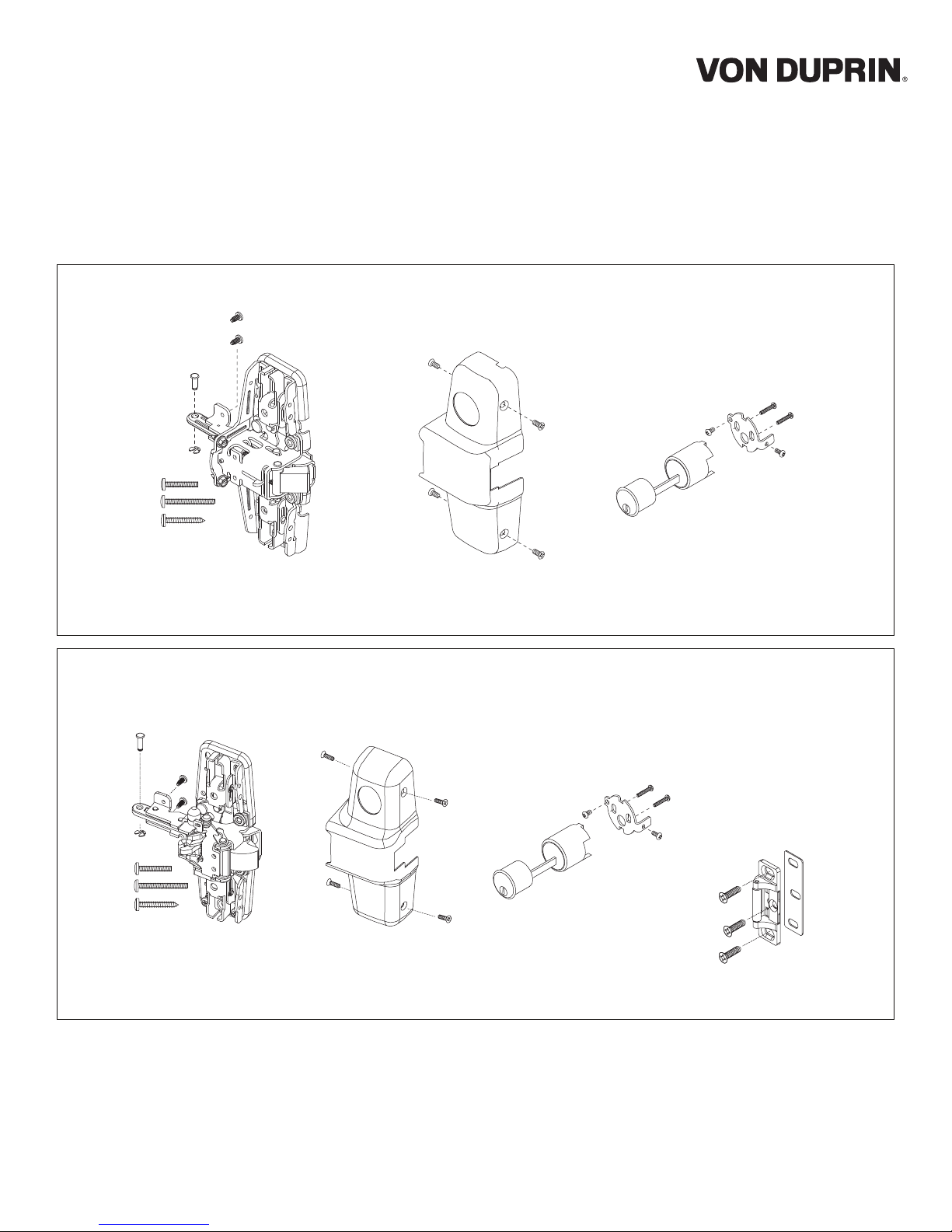
The parts shown below are included with (AX) 98/99 kits:
Center case,
mounting screws,
pin, and retaining ring
Center case
cover and
screws
Cylinder pack
screws
The parts shown below are included with (AX) XP98/99 kits:
Center case,
mounting screws,
pin, and retaining ring
Center case
cover and
screws
Cylinder pack
and
screws
909 strike package
and
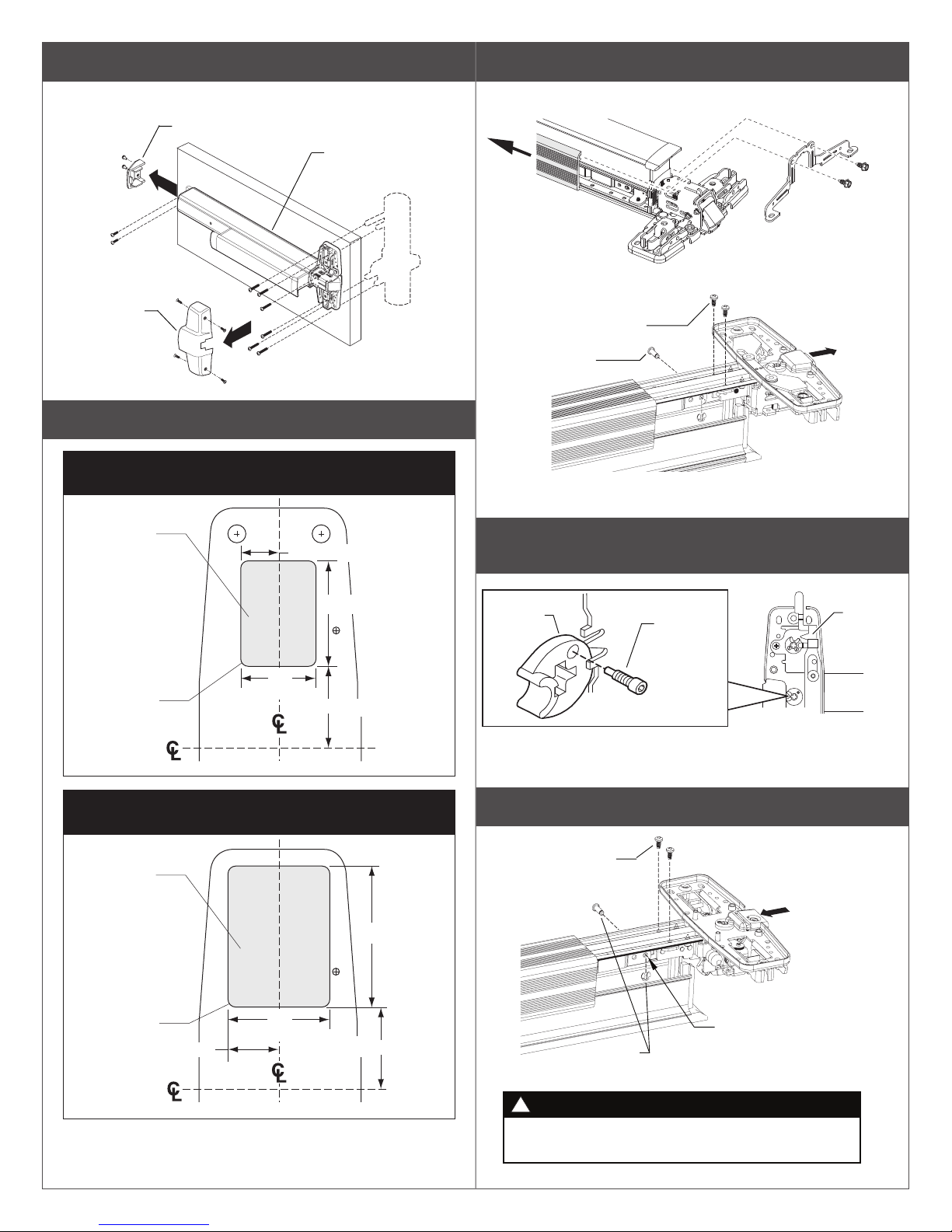
1 Remove existing exit device from door.
3 Remove old center case.
Note: Disconnect device wiring if necessary.
End cap
Center
case cover
2 Prepare door if necessary.
Door Cutout for XP98/99-2 or 98/99-2
"Double Cylinder" Option
Wood
¹⁄₄" (6 mm)
Deep
⁵⁄₈" (16 mm)
Exit device
Trim
A. Slide mechanism case back approximately 5”.
Mechanism
case
B.
Remove retaining ring and pin, and two screws to remove
old center case.
2 screws
Retaining
ring and pin
Center case
(remove)
4 Leave the NL Drive Screw in master cam as shipped
in new center case.
1³⁄₄" (44 mm)
¹⁄₈" (3 mm) R
4 places
1¹⁄₄"
(32 mm)
1³⁄₈" (35 mm)
Device
and Strike
Door Cutout for XP98/99-2SI or 98/99-2SI
"Double Cylinder" Option
Wood
¹⁄₄" (6 mm)
Deep
¹⁄₈" (3 mm) R
4 places
¹³⁄₁₆" (21 mm)
1⁵⁄₈"
(41 mm)
1³⁄₈" (35 mm)
Device
and Strike
2¹⁄₄" (57 mm)
Master
cam
NL drive
screw
New -2SI
center case
5 Attach new center case to device as shown.
Two thread
cutting screws
Pin must go in front
Retaining
ring and pin
!
New retaining ring and pin must be installed securely.
If pin comes out, door will not open properly.
WARNING
New
center case
hole as shown
Lock
slide
 Loading...