

Von Duprin Allegion 3327A Series, Allegion 3527A, Allegion 3527A Series, Allegion 3327A, Allegion 3527A-F Service Manual
...
3327A / 3527A
Series Exit
Device
Service manual
3527A SHOWN

INDEX
3327A/3527A Fire and Panic Devices
Basic Device ...............................................................................................................................
Vertical Rods and Latches ...........................................................................................................
LBR Fire Latch Kit ..........................................................................................................................
Baseplate Assembly .......................................................................................................................
Variations of the Basic Device
CD (Cylinder Dogging) ........................................................................................................
HD-EL (Hex Dogging/Electric Latch Retraction) ...................................................................
EL (Electric Latch Retraction) ..............................................................................................
SS (Signal Switch) ..............................................................................................................
RX (Request to Exit) ......................................................................................................
LX (Latch Bolt Monitoring) ..............................................................................................
ALK (Exit Alarm Kit)......................................................................................................
General Information
Introduction.....................................................................................................................................
How to Order ..................................................................................................................................
Part Number Changes .....................................................................................................................
Finishes .........................................................................................................................................
Outside Trim Functions ..................................................................................................................
Strikes ............................................................................................................................................
4-5
6-7
8
9
4-5
10
11
11
12-13
12-13
14-15
2
2
2
3
3
3
INTRODUCTION
This manual contains a listing of replaceable parts and assemblies for the 3327A/3527A Panic Exit Hardware
Devices. (3327A Series and 3527A Series devices are almost identical. The 3327A Series has a grooved
case; the 3527A Series has a smooth case.)
HOW TO ORDER
Some parts are sold separately. Other items are available as part of a kit or multiple quantity package.
For the best possible service when ordering replacement parts or assemblies, please provide the following
information:
• Part number or assembly number
• Description
• Quantity needed
• Finish desired (if available finished)
• Date of original purchase (if known)
To find out the name of your local Von Duprin distributor or sales representative, contact:
Von Duprin Division
Allegion
2720 Tobey Drive
Indianapolis, IN 46219
Phone: (877) 671-7011
PART NUMBER AND AVAILABILITY CHANGES
This manual was designed to help illustrate the replacement parts and kits that are available for sale.
Because of changes to the product and/or manufacturing process, part numbers and availability can
change over time.
2 • Von Duprin • 3327A/3527A Series Exit Device Service Manual
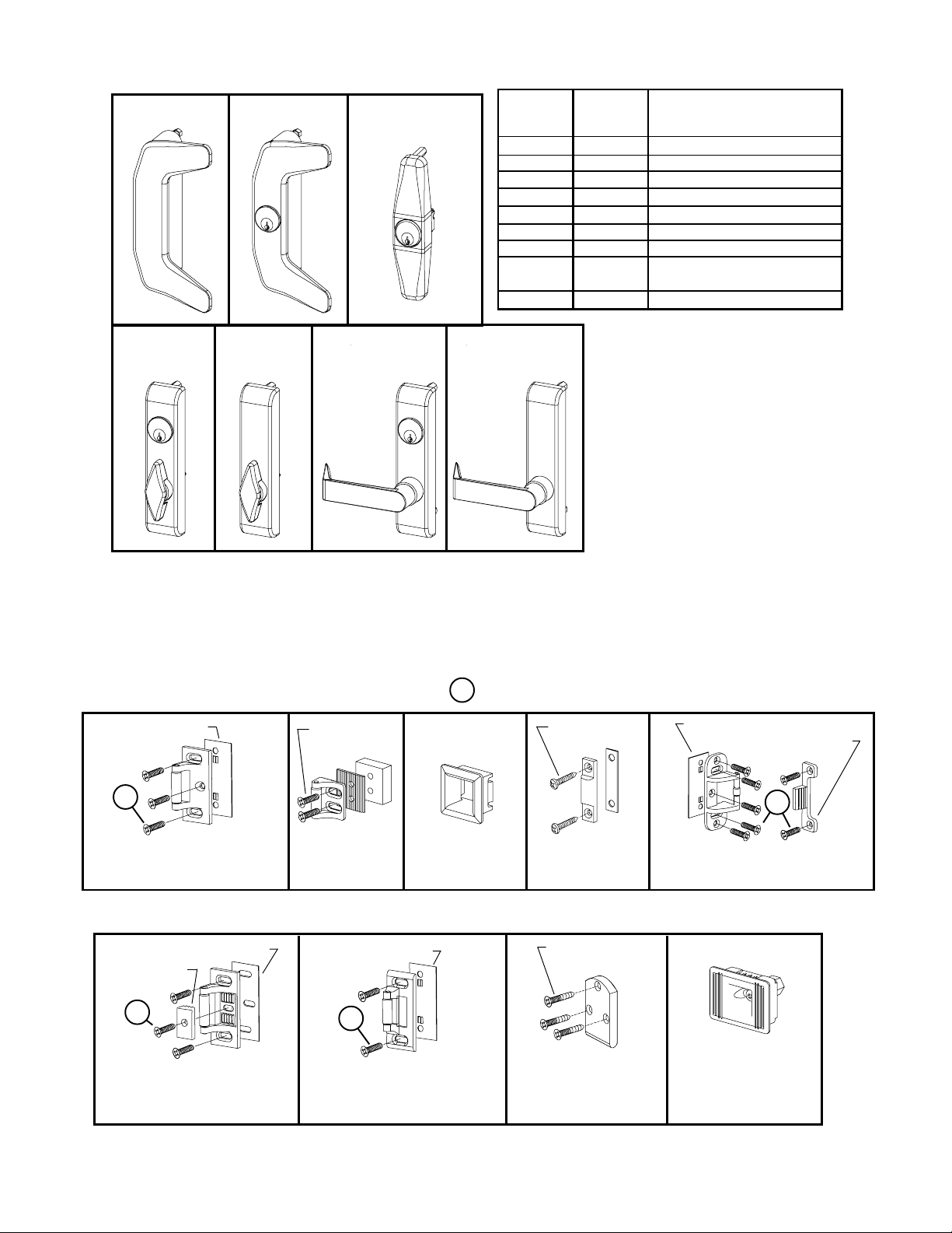
OUTSIDE TRIM FUNCTIONS
386DT***
386NL**
388NL-OP****
33A/35A SERIES FINISHES
U.S. Std
Reference
BHMA
Reference Description
US3
US4
US10
US15
US26
US26D
US28
313AN
315AN
360T
360T-BE* 360L
360L-BE*
360L-DT***
* “BE” (Blank Escutcheon) no cylinder used - lever always active
** “NL” (Night Latch) rigid lever - key retracts latch bolt
*** ”DT” (Dummy Trim) rigid lever for pull operation
**** “NL-OP” (Optional Pull) needs to be added
605
606
612
619
625
626
628
710
711
Polished Brass
Dull Brass
Dull Bronze
Satin Nickel
Polished Chrome
Dull Chrome
Anodized Alum. (Clear)
Anodized Alum. (313)
Dark Bronze
Anodized Alum. (Black)
Metal Door Screw Package PKGSRV.1023 (Pkg of 10)
STANDARD STRIKES
Adjusting Shim
945521
1
299 (Top) Strike - Standard
Single or Double Door
Panic Exit Hardware
(Top) Strike
Screw Pkg
900266
266
(Bottom) Strike
1
Wood Door Screw 964291 (Qty of 1)
Screw Pkg
900263
304L
248L-4
(Bottom) Strike
OPTIONAL STRIKES FOR PANIC EXIT HARDWARE
Adjusting Shim 970321
Strike Plate
970323
1
299 (Top) Strike - Standard
Single or Double Door
Panic Exit Hardware
Adjusting Shim
945521
1
264 (Top) Strike - Single
Door Panic Exit Hardware
Screw Pkg
900252
260U (Top) Strike
For Flush Transom
Applications Only
Adjusting Shim 945521
Strike Hook 969300
1
499F (Top) Strike - Supplied
with LBR Fire Latch/Strike Kit
385A
(Bottom) Strike
Von Duprin • 3327A/3527A Series Exit Device Service Manual • 3
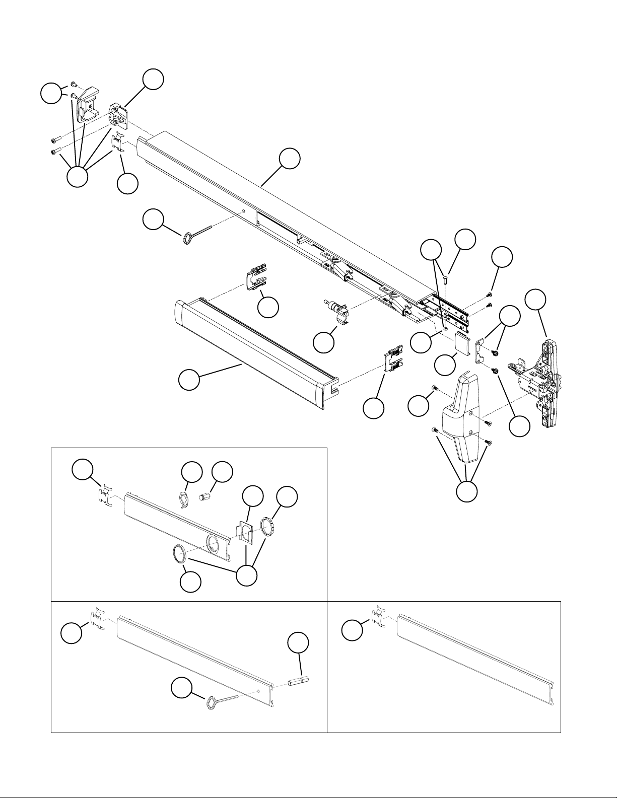
3327A/3527A PANIC AND 3327A-F/3527A-F FIRE EXIT DEVICE
7A
8
9
7
7B
7B
1
10A
10
17
16
6
17
4
5
10B
14
18
11
13
12
12A
3B
PANIC ONLY
CD Conversion Kit
33A Series - 050115
35A Series - 050132
7B
3A
3
PANIC ONLY
Hex Dogging Kit
1
33A Series - 050114
35A Series - 050117
4 • Von Duprin • 3327A/3527A Series Exit Device Service Manual
3C
15
7B
2
Fire or Less Dogging
Cover Plate Kit
33A Series - 050133
35A Series - 050109

3327A/3527A PANIC AND 3327A-F/3527A-F FIRE EXIT DEVICE
Item No. Quantity Part No. Description Finish
1 900619 33A/35A Series Mounting Pkg. (1-3/4 & 2-1/4)
1 1 090085 227 Dog Key 5/32” Hex (Pkg of 10)
1 1 090005 227 Dog Key 5/32” Hex (Pkg of 2)
2 1 090040 Hex Dog Shaft (Pkg of 2)
3 1 107813 XgkP gnitnuoM rednilyC
3A 1 050525 XralloC rednilyC
3B 1 050490 Cylinder Locating Washer - CD/SS
3C 1 050526 Cylinder Locknut
4 1 090046 CD Dogging Plug (Pkg of 2)
5 1 090045 CD Actuator Arm (Pkg of 2)
6 1 *PBKIT 33A/35A Series Push Bar Retrofit Kit - 3’ Door X
6 1 *PBKIT 33A/35A Series Push Bar Retrofit Kit - 4’ Door X
7 1 050014 33A/35A Series End Cap Kit
7A 1 050524 Impact Resistant End Cap Bracket
7B 1 090036 Cover Plate Anti-rattle Spring (Pkg of 10)
8 1 900597 Device End Cap and C/Case Screw Pkg. X
9 1 050486 33A Series Mechanism Case - 3’ Door X
9 1 050487 33A Series Mechanism Case - 4’ Door X
9 1 050488 35A Series Mechanism Case - 3’ Door X
9 1 050489 35A Series Mechanism Case - 4’ Door X
10 1 050529 Control Link Pin & Ret. Ring
10A 1 090031 Control Link Pin (Pkg of 10)
10B 1 090107 Retaining Ring (Pkg of 10)
11 2 090037 #8-32 x 3/8” Baseplate Screw (Pkg of 10)
12 1 050530 Mechanism Case Bracket Kit
12A 2 090073 Mechanism Case Bracket Screw (Pkg of 10)
13** 1 050404 3327A/3527A Center Case Less Cover
14 1 050474 33A Series Cover Plate - C. Case Side X
14 1 050475 35A Series Cover Plate - C. Case Side X
X
15 1 050484 3327A/3527A Center Case Cover Kit X
16 1 050491 Shock Absorber & Holder Assembly
17 2 090049 Push Bar Guide (Pkg of 10)
18 4 900892 Center Case Cover Screws (Pkg of 4) X
X in “Finish” column designates finished items; finish must be specified when ordering.
* To order, specify device type, size, and finish. Example: PBKIT 33A 3’ US28
** Device mounting screws 900619 included.
Von Duprin • 3327A/3527A Series Exit Device Service Manual • 5
 Loading...