

Von Duprin 9849WDC, 9949WDC Installation Instructions Manual
FOR DEVICES SOLD
PRIOR TO
98/9949WDC
4-14-14
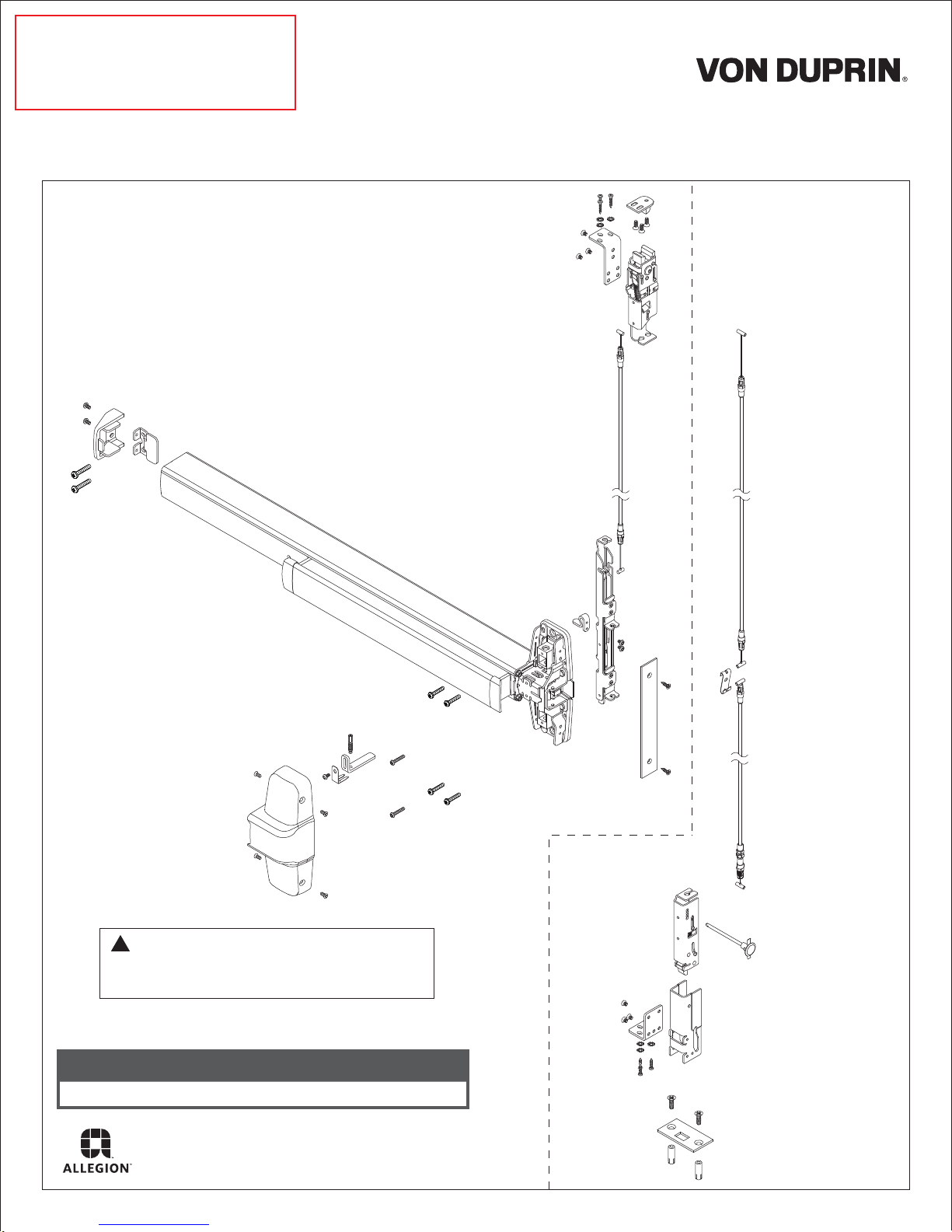
Concealed Vertical Device for Wood Doors Installation Instructions
1-Point
Latch
(LBL)
2-Point
Latch
includes these
additional
parts
!
NOTE: If door does not have a cutout for
cabling inside lock stile, door must be
routed. Refer to 9949 wood door template.
Customer Service
1-877-671-7011 www.allegion.com/us
© Allegion 2014
Printed in U.S.A.
24795361 Rev. 04/14-a

1
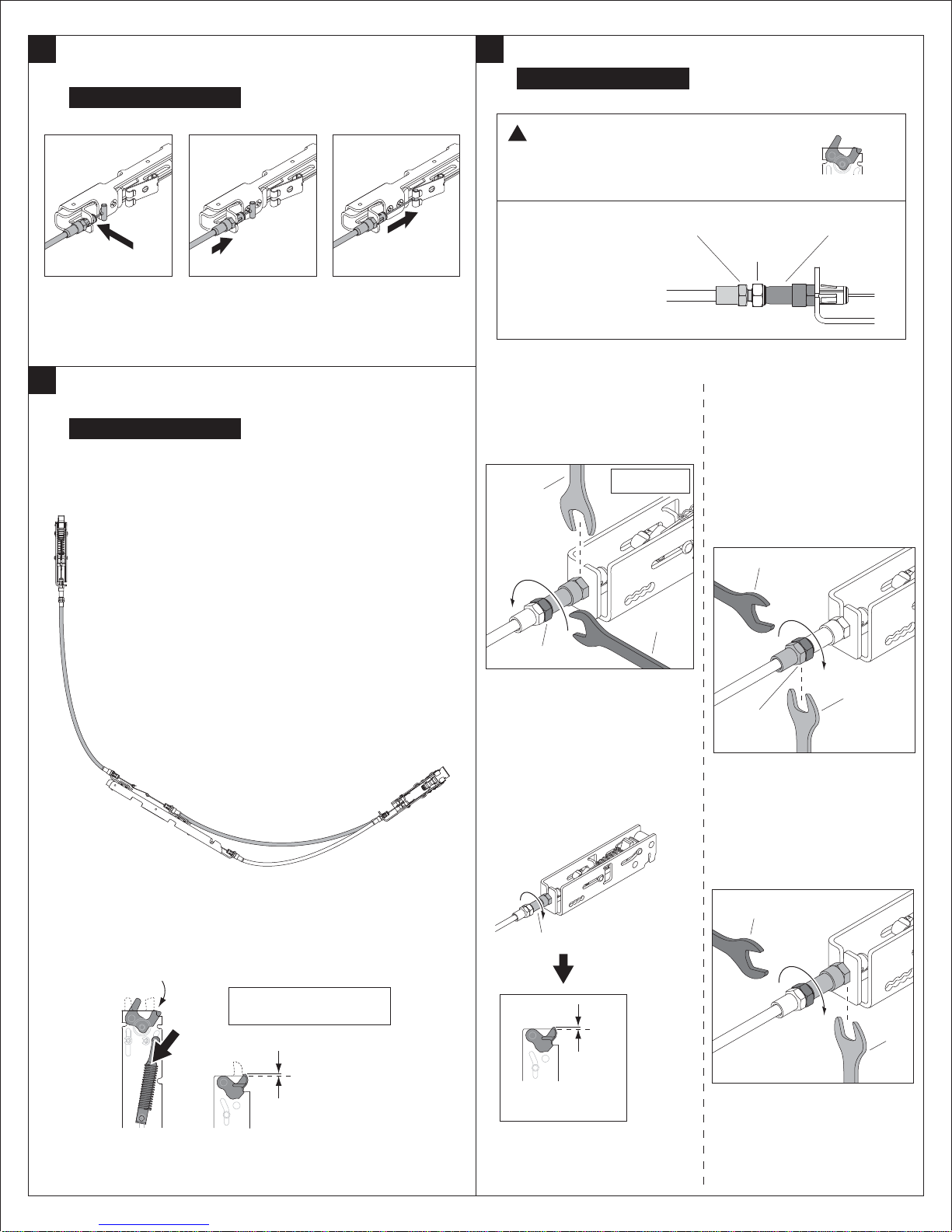
Identify Cables and Locations.
A
B
Door Opening
Height
6' 8"
7' 0"
C
2
Install Top Latch Cable Assembly.
a. Using Cable A, position cable end to clip on center slide, and snap it
into place
8' 0"
9' 0"
10' 0"
a
b. Push cable snap against center slide to secure cable
CABLE IDENTIFICATION
(STANDARD SIZES)
WOOD DOORS
A
24078495
23925787
23925662
23925548
23925423
23925761
23925720
23925605
23925480
24009334
Cable A
cable snap
b
B
C
24078453
24078453
24078453
24078453
24078453
24492399
!
NOTE: Cables A and B are red. Cable C is white
!
NOTE: Cables B is 6" longer than Cable A.
!
NOTE: 98/9949WDC 2-point latch with threshold
requires cable 24492399 (sold separately) for Cable C.
For 2-Point Latch Only
e. Snap cable link onto one end of Cable B
Cable B
cable
link
e
f. Install Cable B to the top mounting bracket
c. Position opposite end of Cable A to the top latch in the position
marked red. Pull cable into clip to snap it into place.
d. Push cable snap against latch to secure cable
!
IMPORTANT:
Ensure cable end is
c
fully seated in clip
d
3
Install Bottom Latch Cable Assembly.
For 2-Point Latch Only
One end of Cable C has an adjuster. Install this end
to the bottom latch.
!
IMPORTANT:
Ensure cable end is
fully seated in clip
adjuster
Cable C
f
g. Install opposite end of Cable B to the remaining
top latch position (marked as white)
top mounting bracket
Ensure cable end is
fully seated in clip
!
IMPORTANT:
g
CABLE REMOVAL
A cable removal tool has been provided. Slot in tool fits over cable,
holding tabs down. Pull on cable snap to loosen cable for removal.
cable
slot
a
snap
b
2
4
Temporarily Attach Bottom Latch Cable Assembly
to Center Slide.
For 2-Point Latch Only
6
Adjust Bottom Latch Retraction (if necessary).
For 2-Point Latch Only
NOTE: Adjustment must be made while the top
!
latch is in the hold-open position, with cable
flexed into an L-shape to simulate the installed
condition of the latches.
a
b
Position Cable C to
bottom mounting
bracket on center slide
5
Determine if Bottom Latch Retraction Adjustment is
Necessary.
For 2-Point Latch Only
a. Flex the cable into an L-shape as shown to simulate the installed
condition of the latches.
Push cable snap
against mounting
bracket to secure
cable
Pull on cable end to
attach it to the cable
link
These (3) hex
c
components
are used to
make the
adjustment.
a. While holding the snap-fitting
with a ³⁄₈" wrench, use a 10mm
wrench to break loose the lock
nut.
³⁄₈"
lock nut
bottom latch
conduit cap
locknut
c. While holding the conduit cap
with a ³⁄₈" wrench, use a 10mm
wrench to turn the locknut in a
clockwise direction to close the
gap between the lock nut and
snap-fitting. Stop when the gap
is closed and the snap-fitting
begins to turn with the locknut.
10mm
10mm
snap-fitting
b. To determine whether an adjustment is required, actuate the top
latch to the hold-open position by pressing down on the connecting
rod. Bottom latch should retract to within ¹⁄₁₆" of flush. If it does not,
an adjustment is necessary.
If no adjustment is needed,
press
top latch
(hold-open
position)
proceed to Step 7.
¹⁄₁₆"
flush
bottom latch
(retracted)
b. While holding the lock nut in
place, rotate the barrel of the
snap-fitting clockwise by hand
until the bottom latch is
retracted to within ¹⁄₁₆" of flush.
snap-fitting
flush
¹⁄₁₆"
bottom latch
(retracted)
³⁄₈"
conduit
cap
d. While holding the snap-fitting
with a ³⁄₈" wrench, continue to
tighten the locknut until it is
secure.
10mm
³⁄₈"
3
7
Disconnect Bottom Latch Cable Assembly from
Center Slide.
For 2-Point Latch Only
8
With Door Laying Flat, Draw Horizontal and Vertical
Device Center Lines ( ).
a
Disconnect cable end
from cable link
c
Pull on cable snap to
loosen cable for
removal
b
A cable removal tool has been
provided. Slot in tool fits over
cable, holding tabs down
d
Remove bottom latch
cable assembly from
center slide.
RHR shown
(LHR opposite)
!
NOTE: Centerlines
predetermined by cutout.
If no cutout exists, refer
to Step 10 to determine
centerlines.
9
Align Plastic Template to Mark and Prepare Door, if
Required.
!
NOTE: This hole is to be ¹⁄₂"
diameter (disregard larger center
hole of plastic template).
2¹⁄₂"
Backset
Plastic
Template
4
 Loading...