

Von Duprin (AX) 98/99-2, (AX) 98/99, (AX) 98/99-2SI, (AX) XP99-2SI, (AX) XP99-2 Installation Instructions Manual
...Page 1
*941363-00*
(AX) 98/99-2, (AX) 98/99-2SI,
941363-00
Center Case Retrot / Replacement Installation Instructions
(AX) XP99-2, (AX) XP99-2SI
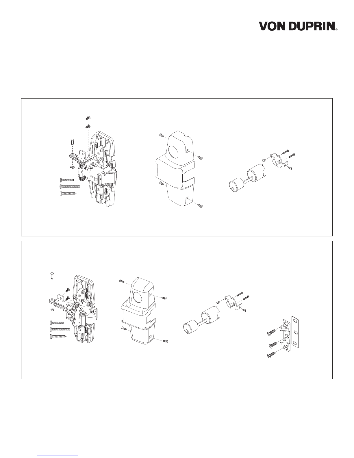
The parts shown below are included with (AX) 98/99 kits:
Center case,
mounting screws,
pin, and retaining ring
Center case
cover and
screws
Cylinder pack
screws
The parts shown below are included with (AX) XP98/99 kits:
Center case,
mounting screws,
pin, and retaining ring
Center case
cover and
screws
Cylinder pack
and
screws
909 strike package
and
Page 2
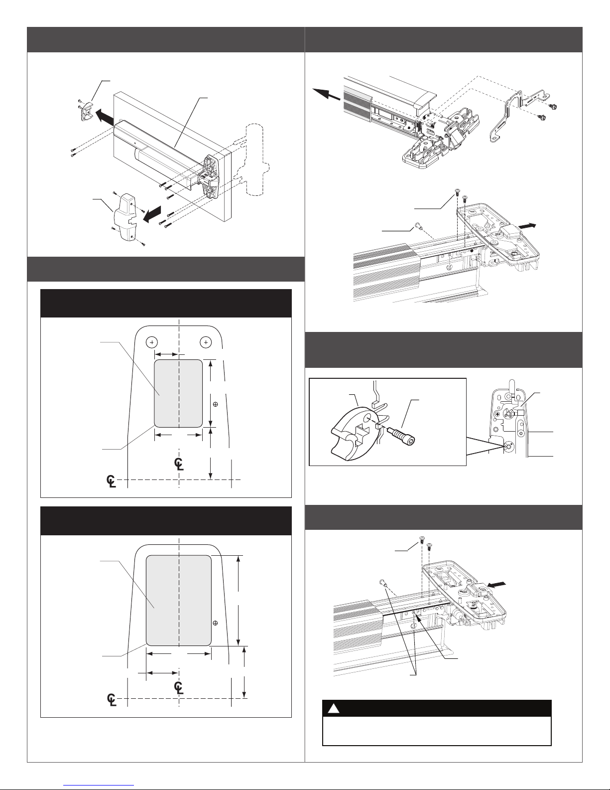
1 Remove existing exit device from door.
3 Remove old center case.
Note: Disconnect device wiring if necessary.
End cap
Center
case cover
2 Prepare door if necessary.
Door Cutout for XP98/99-2 or 98/99-2
"Double Cylinder" Option
Wood
¹⁄₄" (6 mm)
Deep
⁵⁄₈" (16 mm)
Exit device
Trim
A. Slide mechanism case back approximately 5”.
Mechanism
case
B.
Remove retaining ring and pin, and two screws to remove
old center case.
2 screws
Retaining
ring and pin
Center case
(remove)
4 Leave the NL Drive Screw in master cam as shipped
in new center case.
1³⁄₄" (44 mm)
¹⁄₈" (3 mm) R
4 places
1¹⁄₄"
(32 mm)
1³⁄₈" (35 mm)
Device
and Strike
Door Cutout for XP98/99-2SI or 98/99-2SI
"Double Cylinder" Option
Wood
¹⁄₄" (6 mm)
Deep
¹⁄₈" (3 mm) R
4 places
¹³⁄₁₆" (21 mm)
1⁵⁄₈"
(41 mm)
1³⁄₈" (35 mm)
Device
and Strike
2¹⁄₄" (57 mm)
Master
cam
NL drive
screw
New -2SI
center case
5 Attach new center case to device as shown.
Two thread
cutting screws
Pin must go in front
Retaining
ring and pin
!
New retaining ring and pin must be installed securely.
If pin comes out, door will not open properly.
WARNING
New
center case
hole as shown
Lock
slide
Page 3
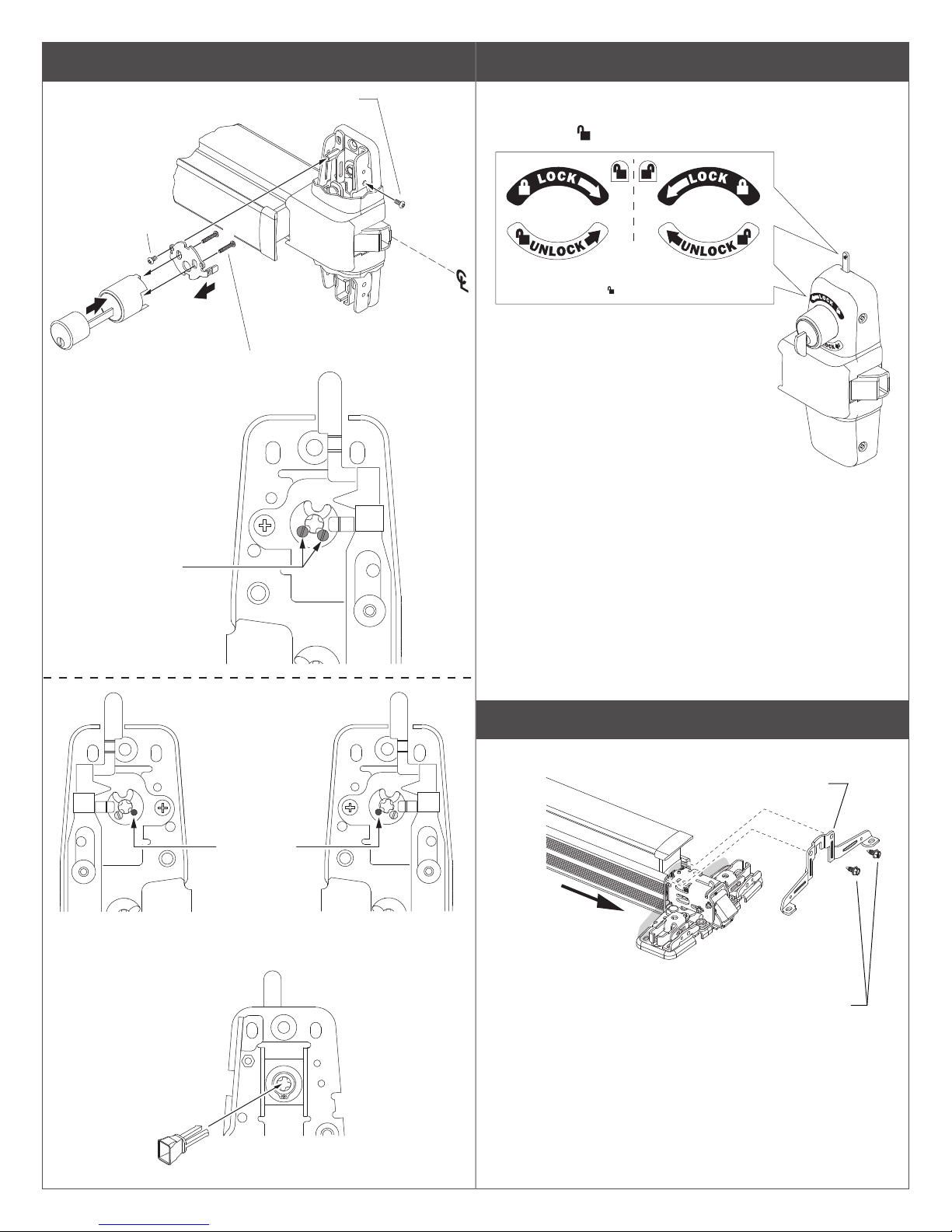
6 Mount key cylinder.
7 Apply label.
#8-32 x ⁵⁄₁₆" (8 mm)
PPHMS
d
a
Mounting Screws
DO NOT over-tighten
If using the -2SI with a
keyed rim cylinder,
remove the 2 stop screws
from back of device prior
to installing the cylinder.
#8-18 x ³⁄₈" (10 mm)
c
b
Cylinder
PPHSMS
RHR Shown
(LHR opposite)
For 98/99-2SI models with Classroom Security Indicator,
apply supplied labels above and below cylinder to match door
handing, and label on indicator.
e
LHR99-2 RHR99-2
Peel and stick
appropriate set of
labels depending on
door handing. Stick labels
above and below cylinder,
and label on indicator.
RHR shown
L Manually ax the label:
Ensure surface is clean of dirt, dust, or oils. Clean with
alcohol if necessary.
Peel the label from the paper backing and apply to the
surface. Minimize handling when applying and use
pressure to burnish label to surface. The adhesive will
require up to 8 hours to achieve the proper bond.
LHR
Back of Device
From front side of
device, insert
tailpiece guide into
master cam. It will
snap into location.
B
A
If using the -2SI
with a thumbturn,
remove this screw
from back of
device prior to
installing the
thumbturn
cylinder.
(device shown in
unlocked position)
Front of Device
8 Slide mechanism case forward and install bracket.
New bracket
Slide mechanism
case forward
RHR
Back of Device
New screws
Page 4
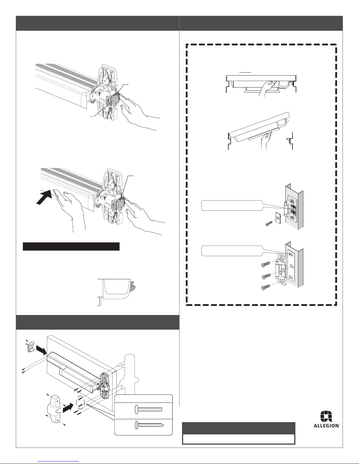
9 Check latch function as shown.
Push
11 Perform operational check.
A. Depress auxiliary bolt and check latch bolt.
Latch bolt should be locked and will not move
while auxiliary bolt is depressed.
Auxiliary
bolt
Latch bolt
(locked)
B. With auxiliary bolt still depressed, press and hold
device push bar. Press latch bolt from top and bottom.
It should depress freely in both directions.
Latch bolt
bar
(moves freely)
L Important!
A. With door closed, push against
door without touching device.
Device should NOT allow door to open.
B. With door closed, push device push bar.
Device should allow door to open.
C. If device does not function as described, adjust
strike position and continue operational check until
device functions as described above.
D. Install strike support screw.
#25 Drill, #10-24 tap
Note about the XP latch operation
The XP latchbolt operates differently from a standard
latchbolt. When the pushbar is depressed, the latchbolt
does not retract. This is
normal because the XP
latchbolt can swivel in
both directions.
Latchbolt
10 Reinstall device.
Note: Reconnect device
wiring, if necessary.
Two New Screws
299 Strike
#7 Drill, ¼”-20 tap
909 Strike for XP Product
Metal
Wood
#10-24 X 1”
#10 X 1-1/4”
Customer Service
1-877-671-7011 www.allegion.com/us
© Allegion 2018
Printed in U.S.A.
941363-00 Rev. 08/18-c
Page 5
Additional Notes: Revision History Revision Description:
C > Revised document
1. None A B C D E F
58294 58807
Material
White Paper
Edited By Approved By EC Number Release Date
J. Ellis M. Roberts 08-21-18
Notes
1. printed two sides on 11x17 sheet
2. printed black
3. folded into 8.5x11 4-page booklet
4. tolerance ± .13
5. printed in country may vary
6. drawings not to scale
Title
99-2/2-SI Center case retrot/replacement instruction
Creation Date
xx-xx-xx
Number
941363-00
Revision
C
Created By
J. Ellis
Activity
3899 Hancock Expwy
Security, CO 80911
© Allegion 2018Software: InDesign CS6
17.000
11.000
BEGINNING SHEET
8.500
11.000
FOLDED SHEET
FRONT COVER WITH BARCODE
 Loading...