

Von Duprin 7500 Installation Instructions Manual
*941019-00*
941019-00
1. Prepare door for device and trim (see their
instructions).
2. Prepare door for mortise lock and cylinder (see
preparation on other side of these instructions).
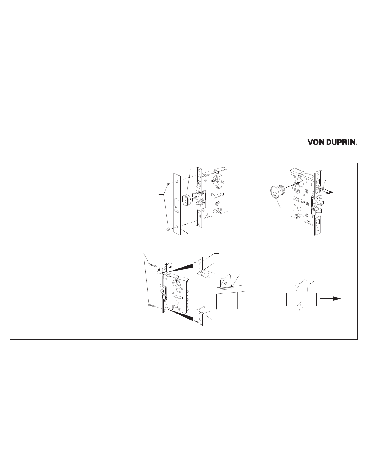
3. Adjust faceplate for door bevel (Figure 2):
(a) Loosen top and bottom faceplate screws.
(b) Pivot faceplate to match door bevel.
(c) Tighten top and bottom faceplate screws.
4. Install mortise lock into door with two #12-12 x 12-24 x 1”
combination screws.
5. Install trim, if required (see trim instructions).
6. If using outside cylinder (Figure 3):
(a) Back out cylinder set screws enough to clear
cylinder mounting hole.
(b) Thread cylinder into mortise lock through
hole in outside face of door.
(c) Tighten the cylinder set screw that is closest
to outside face of door. Remove the other
cylinder set screw.
7. Rotate latch bolt so flat side faces exit direction.
(Figure 4).
8. Install collar, scalp plate, and scalp plate
retaining screws (Figure 1).
Figure 4
Exit direction
Flat side of
latch bolt
Top view
#12-12 x 12-24 x 1”
combination screws
Faceplate
Faceplate screw
Faceplate screw
Figure 2
Retaining
screws
Scalp plate
Figure 1
Collar
Keyhole
position when
installed
Cylinder set
screws
Door not
shown for
clarity
Figure 3
Faceplate
Bevel on
edge of
door
}
Equal
angles
Mortise Lock
7500
Installation Instructions
© Allegion 2014
Printed in U.S.A.
941019-00 Rev. 01/14-c
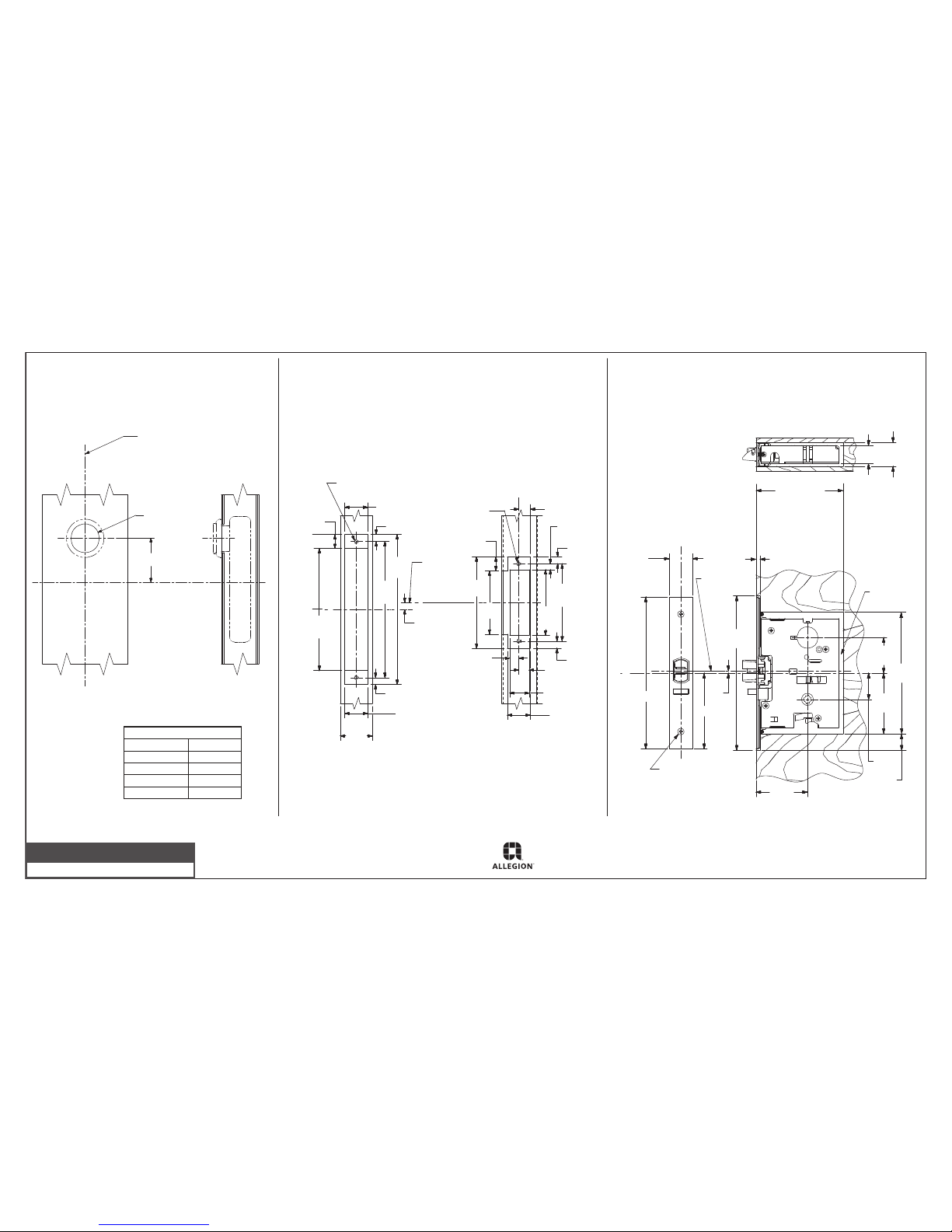
METAL DOOR PREPARATION
FOR MORTISE LOCK
WOOD DOOR PREPARATION
FOR MORTISE LOCK
1-1/4”
4-1/2” min.
clearance required
for 7500 lock
4-11/16” min.
clearance required
for SS7500 and
E7500 locks
1”
1/8”
4”
1-3/8”
1-7/8”
3-1/8”
6-1/2”
2-3/4”
8”
C
L
Latch
bolt
15/16”
Raceway
area
Mortise
lock
C
L
7/32”
1-1/4”
8”
1/8” drill pilot
hole 3/4” deep
2 places
DOOR PREPARATION
FOR MORTISE CYLINDER
Door Dimensions
Frame Dimensions
3/4” max.
#12-24 tap
2 places
1-1/4”
3/8”
6-1/2”
1-3/4”
1-1/4”
3/8”
8”
7-1/4”
3/8”
C strike
L
1-1/4”
1-1/16”
9/16”
min.
3/8”
1/2” min.
4-7/8”
3-3/8”
3-1/2
min.
4-1/8”
3/8”
5/16” min.
5/8”#12-24 tap
2 places
3/4” max.
C
lock and strike
L
C lock
L
Device Application Schedule
Device
55 mortise
88 mortise
98/99 mortise
94/95 mortise
Dim. “A”
2”
2”
2-7/32”
10-3/8”
Corresponds to
centerline of device
on device template
1-5/16”
diameter
Line X-X corresponds to
line X-X on device template
“A”
Outside
face of
lock stile
C
L
Customer Service
1-877-671-7011 www.allegion.com/us
 Loading...