

Von Duprin 6226, 6226DS Installation Instructions Manual
*931241-00*
6226/6226DS
931241-00
Electric Strike, Double Door Closed Back Mortise or
Cylindrical Application
Installation Instructions
Notes: Deadbolt will not function with this strike.
1. For lock or device preparation, see their directions.
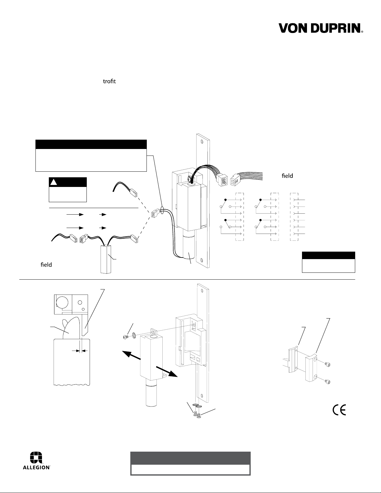
2. Prepare door for strike (see other side).
3. Wire strike (Figure 1). (Switches on 6226DS only.)
Wiring
for DC
supply
Wiring
for AC
supply
Check with factory for re applications.
SOLENOID POWER REQUIREMENTS
Yellow solenoid wires = 12 VDC, 0.57 A
Black solenoid wires = 24 VDC, 0.29 A
(also shown on strike label)
NOTE
!
DC input is
{
nonpolarized.
12 VAC SO-12 12 VDC
or
24 VAC SO-24 24 VDC
12 VDC
or
24 VDC
{
Use crimp
connectors to
splice wiring
to P1 leads
P1 J1A P1A
P1
SO-12 or SO-24
Figure 1
J1
4. Test strike: Apply solenoid power. Fail secure (FSE) lip unlocks.
Fail safe (FS) lip locks. Figure 1 shows status of switches.
5. Install strike with two #12-24 screws. Make sure clearance
between latch bolt and strike lip is 1/32” (Figure 2). If not,
uninstall strike, adjust (Figure 3), and reinstall.
6. If latch bolt does not extend far enough to actuate tripper,
install extension (Figure 4). (Tripper on 6226DS only.)
7. Test door: With strike unlocked, door opens
with latch bolt extended. When door closes,
latch bolt rides over strike lip.
Use crimp connectors to
splice
leads; insulate unused leads
S1
S2
1
2
3
4
5
6
wiring to P2
P2
Red (C)
Blue
Yellow
White (C)
Gray
Violet
Standard: 5 A, 30 VDC
Gold: 0.25 A, 30 VDC
Solenoid
P2
J2
S1
S2
Fail safe (FS)J2Fail secure (FSE)
depressed, strike lip closed and locked
(switches and tripper on 6226DS only)
1
2
3
4
5
6
J2
Switches shown with tripper
(monitors
}
tripper)
(monitors
}
strike lip)
SWITCH RATINGS
S1
S2
Latch bolt
Strike lip
1/32”
Top view;
faceplate not
shown for clarity
Figure 2
NOTE:
Static Strength Rating 1500 lb.
Dynamic Strength Rating 70ft.-lb.
Endurance Rating 250,000 c.
A
To adjust strike,
loosen screws A, B,
and C and move
backbox sideways
as necessary
B
C
Figure 3
Customer Service
1-877-671-7011 www.allegion.com/us
Tripper
Figure 4
Extension
931241-00 Rev. 01/14-b
89/336/EEC
© Allegion 2014
Printed in U.S.A.
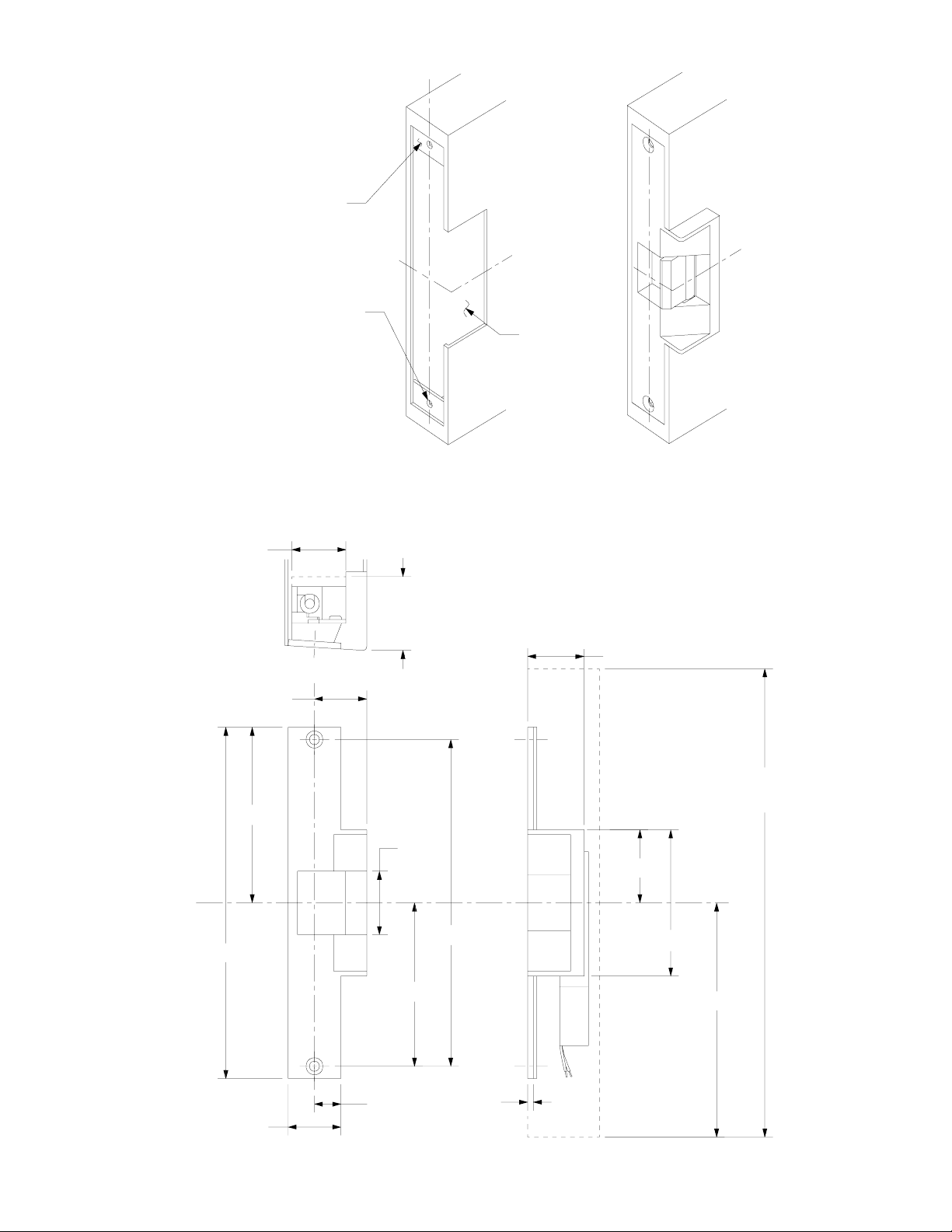
LHR shown
RHR opposite
RHR door
shown inactive
Reinforce for strike
attachment as required
#16 drill and
#12-24 tap
2 places
C door
L
C strike
L
Suggested
cutout
Door Preparation for Strike
1-7/16” minimum
clearance
backbox
assembly
Lock and strike C
C strike
L
and
latch bolt
9”
Strike
1-3/8”
4-1/2”
1-7/8”
minimum
clearance
1-1/2”
L
12” minimum
clearance
1-5/8”
1-7/8”
8-3/8”
4-3/16”
3-3/4”
6”
1-3/8”
11/16”
5/32”
Strike Dimensions and Required Clearances
 Loading...