

Von Duprin 6210, 6210DS Installation Instructions Manual
*931001-00*
89/336/EEC
6210/6210DS
931001-00
Electric Strike Single Door Mortise Application
Installation Instructions
Notes: Deadbolt will not function with this strike. Check with factory for retrot applications.
1
For lock or device preparation, see their directions.
2
Prepare frame for strike (see other side).
3
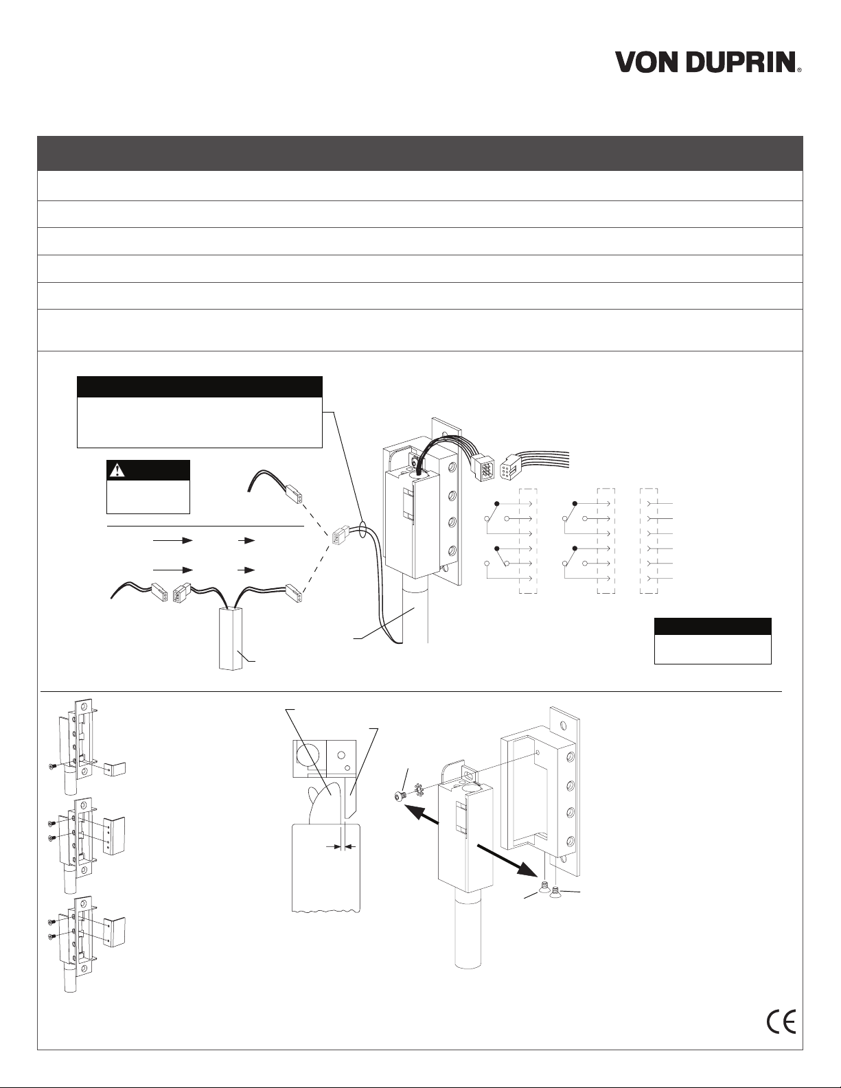
Wire strike (Figure 1). (Switches on 6210DS only.)
4
Install insert for auxiliary bolt operation (Figure 2).
5
Test strike: Apply solenoid power. Fail secure (FSE) lip unlocks. Fail safe (FS) lip locks. Figure 1 shows status of switches.
6
Install strike with two #12-24 screws. Make sure clearance between latch bolt and strike lip is 1/32” (Figure 3). If not, uninstall strike, adjust (Figure 4),
and reinstall.
7
Test door: With strike unlocked, door opens with latch bolt extended. When door closes, latch bolt rides over strike lip.
SOLENOID POWER REQUIREMENTS
Yellow solenoid wires: 12 VDC, 0.57 A
Black solenoid wires: 24 VDC, 0.29 A
(also shown on strike label)
Wiring
for DC
supply
Wiring
for AC
supply
Use crimp
connectors to
splice field wiring
to P1 leads
DC input is
{
nonpolarized
12 VAC SO-12 12 VDC
or
24 VAC SO-24 24 VDC
{
NOTE
P1 J1A P1A
12 VDC
or
24 VDC
P1
J1
Solenoid
SO-12 or SO-24
Figure 1
J2 P2
S1
S2
Fail safe (FS)J2Fail secure (FSE)
Switches shown with tripper
depressed, strike lip closed and locked
(switches and tripper on 6210DS only)
1
2
3
4
5
6
J2
Use crimp connectors to
splice field wiring to P2
leads; insulate unused leads
S1
S2
1
2
3
4
5
6
Red (C)
Blue
Yellow
White (C)
Gray
Violet
P2
SWITCH RATINGS
Standard: 5 A, 30 VDC
Gold: 0.25 A, 30 VDC
(monitors
}
tripper)
(monitors
}
strike lip)
S1
S2
Insert and location
for Von Duprin
mortise locks
Insert and location
for Schlage
mortise locks
Insert and location
for Yale, Best, and
Sargent mortise
locks
Figure 2
Latch bolt
Strike lip
1/32”
Top view;
faceplate not
shown for clarity
Figure 3
A
To adjust strike, loosen screws
A, B, and C and move backbox
sideways as necessary
Figure 4
NOTE:
Static Strength Rating 1500 lb.
Dynamic Strength Rating 70ft.-lb.
Endurance Rating 250,000 c.S
B
C
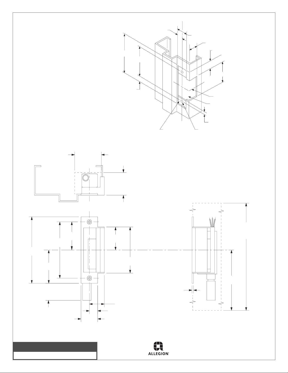
Strike Dimensions and Required Clearances
4-7/8”
4-1/8”
3/8”
LHR shown
RHR opposite
C lock and strike
L
5/8”
Reinforce for
strike attachment
as required
1-1/4”
#16 drill and
#12-24 tap
2 places
1-9/16”
3/4”
3-3/8”
C strike
L
Suggested
cutout
1/4” maximum
4-7/8”
Strike
backbox
assembly
4-1/8”
2-7/16”
2-1/16”
2” minimum
clearance
C lock and strike
L
1-3/4”
minimum
clearance
1-11/16”
3-3/8”
Frame Preparation for Strike
C strike
L
12” minimum
clearance
6”
1-1/4”
1-1/4”
1-1/8”
5/8”
1/8”
© Allegion 2014
Printed in U.S.A.
931001-00 Rev. 01/14-c
 Loading...