

Von Duprin 388NL Installation Instructions Manual
*941093-00*
941093-00
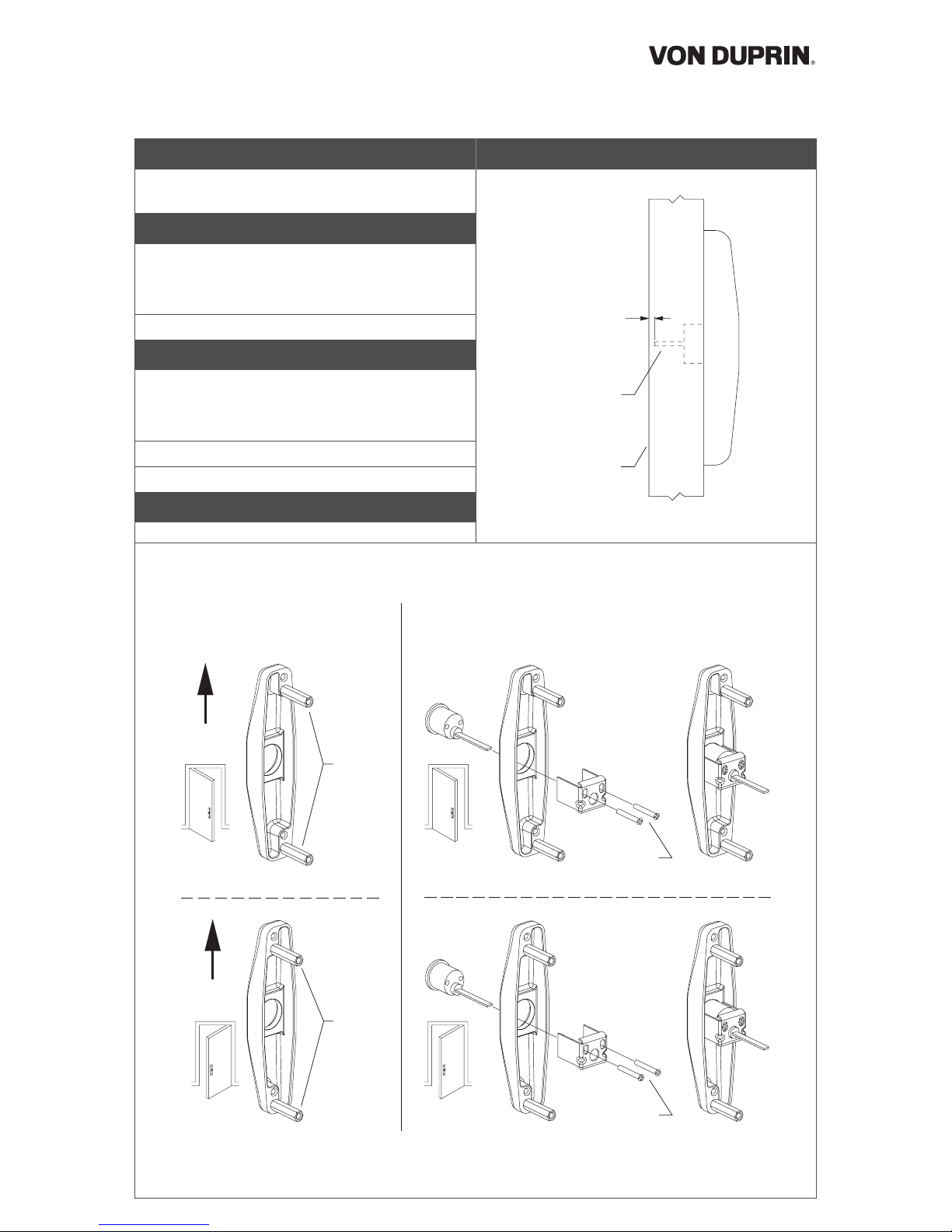
CONTROL AND MOUNTING
STUD POSITIONS
TO INSTALL CYLINDER
Rim
cylinder
Cylinder
bracket
Cylinder screws
(cut to length)
Rim
cylinder
Cylinder
bracket
Cylinder screws
(cut to length)
UP
UP
RHR
Outside
L
ock
stile
LHR
Outside
Lock
stile
Note
stud
positions
Note
stud
positions
RHR
Outside
Lock
stile
LHR
Outside
Lock
stile
1 Prepare door for exit device.
See exit device instructions for locations of holes, backset
(line X-X) and center lines.
2 Prepare door for control:
2a Transfer line X-X from inside (exit device) side of door
to outside (control side) of door. Use extra care if edge
of door is beveled. Be sure line X-X is parallel to edge
of door.
2b Locate and prepare holes as shown on other side.
3 Prepare control:
3a Orient control as shown for your application (RHR or
LHR) and make sure mounting studs are in positions
shown. If not, move mounting studs to correct
positions.
3b Install cylinder.
3c If necessary, adjust tailpiece length.
4 Apply exit device and control.
To Adjust Tailpiece Length
Cut cylinder tailpiece as shown.
1/8”
Inside
face
of door
Cylinder
tailpiece
Cylinder Control
388NL
Installation Instructions
© Allegion 2014
Printed in U.S.A.
941093-00 Rev. 01/14-b
Customer Service
1-877-671-7011 www.allegion.com
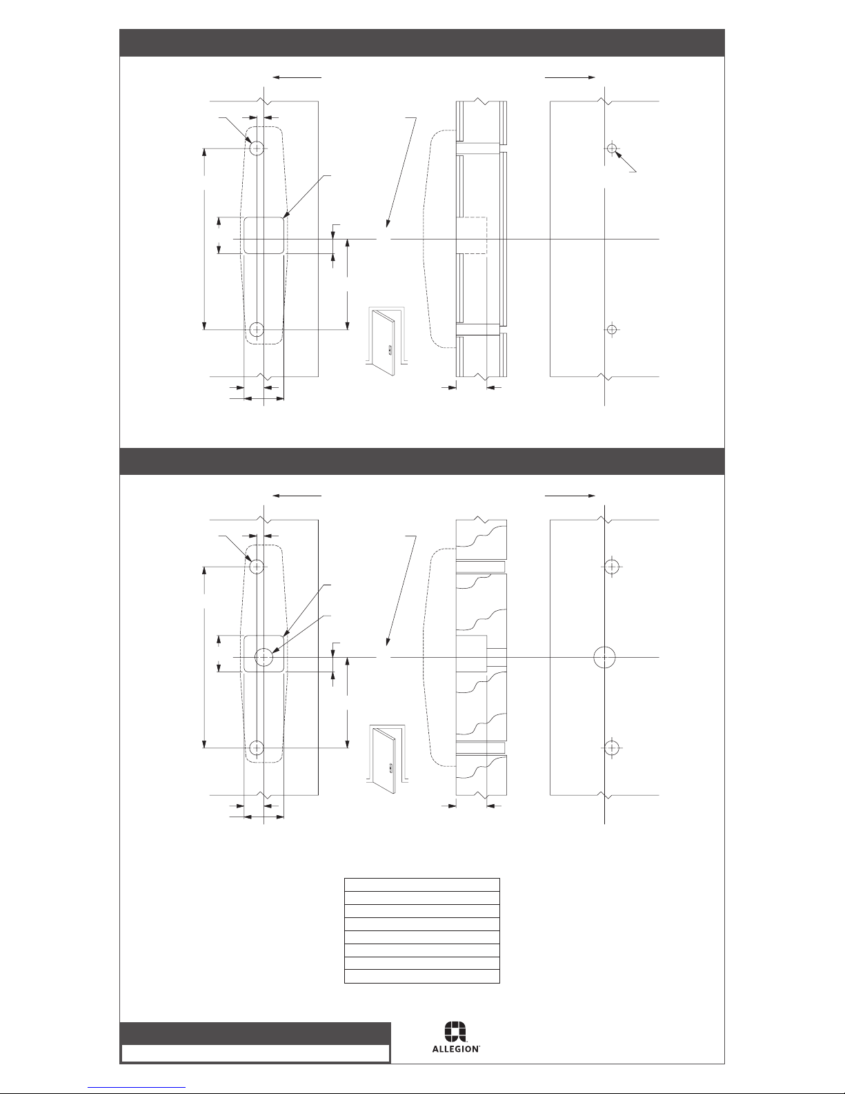
Door Preparation, Metal Door Application
LHR shown
RHR opposite
1/4”
6-1/4”
1” clear
depth
required
1-3/8”
3-1/8”
1/8” R
4 places
1/2”
dia.
2 places
5/16” dia.
2 places
X
X
X
X
Line X-X corresponds to line X-X on exit device instructions
Outside
face of
lock stile
Inside
face of
lock stile
C
L
Corresponds to
center line of exit
device on exit
device instructions
9/16”
1-7/16”
23/32”
Outside
Lock
stile
Door Preparation, Wood Door Application
LHR shown
RHR opposite
1/4”
6-1/4”
1”
1-3/8”
3-1/8”
1/8” R
4 places
1/2”
dia.
2 places
X
X
X
X
Line X-X corresponds to line X-X on exit device instructions
Outside
face of
lock stile
Inside
face of
lock stile
C
L
Corresponds to
center line of exit
device on exit
device instructions
9/16”
1-7/16”
23/32”
5/8” dia. thru
Outside
Lock
stile
For cutouts on inside face of door, see exit device instructions.
Device Application Schedule
33A/35A Rim Device
3327A/3527A Vertical Rod Device
3347A/3547A Vertical Rod Device
3348A/3548A Vertical Rod Device
3327A-F/3527A-F Vertical Rod Device
3347A-F/3547A-F Vertical Rod Device
3348A-F/3548A-F Vertical Rod Device
 Loading...