

Von Duprin 377-T, 377-T-BE Installation Instructions Manual
*941116-00*
941116-00
Control for Metal Door Application
377-T & 377-T-BE
Installation Instructions
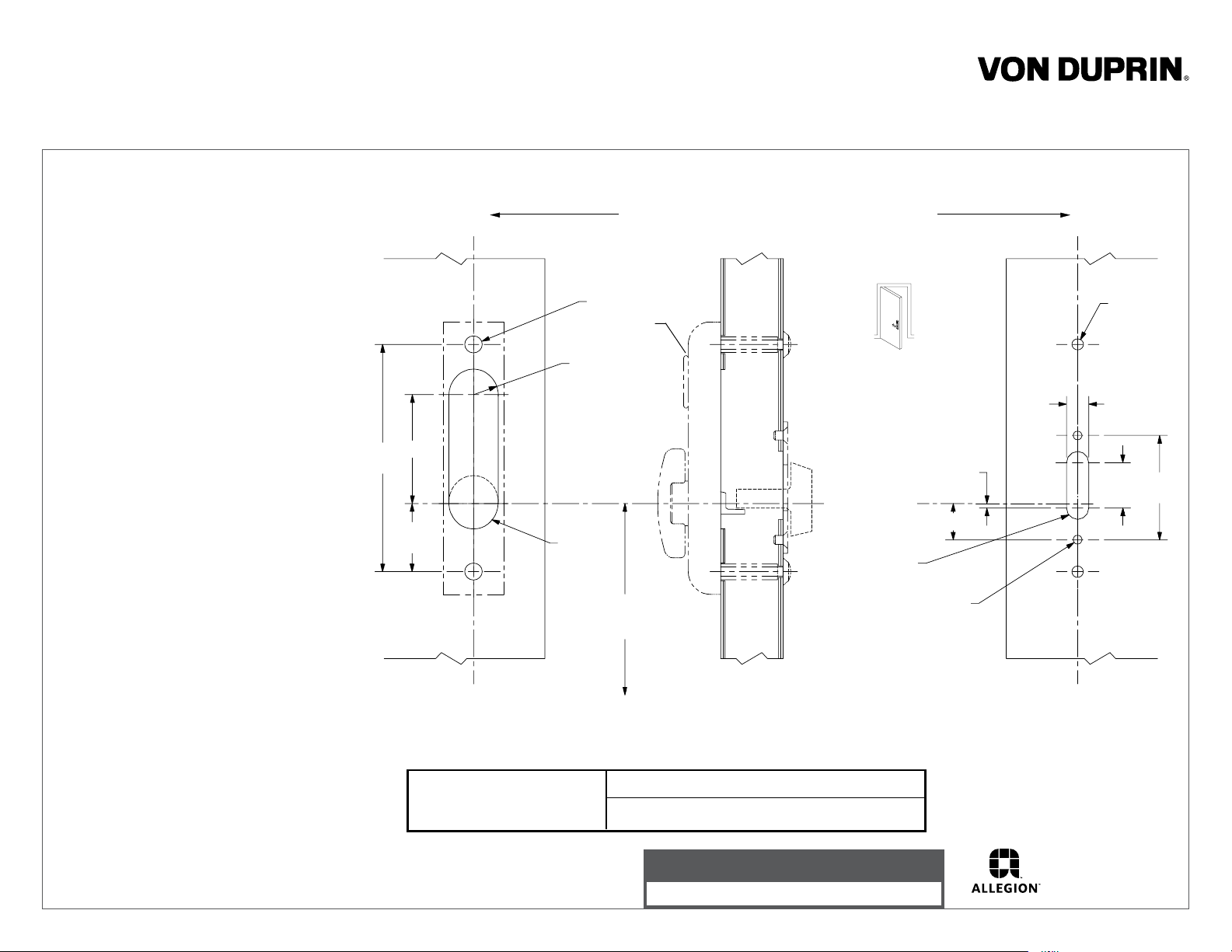
1. Prepare door for exit device. See exit
device instructions for locations of
holes, backset (line X-X), and center
lines.
2. Prepare door for control:
A. Transfer line X-X from inside (exit
device side) of door to outside
(control side) of door. Use extra
care if edge of door is beveled.
Be sure line X-X is parallel to edge
of door.
B. Locate and prepare holes as
indicated.
3. Install cylinder if required (Figs. 1 &2).
Insure cylinder cam is set for required
function and replace if necessary.
4. Install control and rub plate (Fig. 2)
5. Slip rod member on top rod.
6. Install top rods (see direction for
vertical rod device).
6-1/4”
3”
1-7/8”
X
Line X-X corresponds to line X-X on exit device instructions
1/2” dia.
2 places
Omit cylinder
for BE function
11/16” R, 2 places
(omit for BE)
1-3/8” dia.
(BE only)
53-1/2” to
finished floor
LHR shown
RHR opposite
of thumbturn
C
L
1”
R
2 places
1/4”-20 tap
2 holes
1/8”
X
5/16” dia.
2 places
5/8”
1-1/4”
2-7/8”
7. Position rod member so finger contacts
cam when top latch bolt is extended.
8. Tighten set screws in rod member.
9. Apply device and test key, control,
and device action.
Outside
face of
lock stile
For cutouts on inside face
of door see instructions in
device carton
X
Device Application Schedule
4427, 8827, 8827-F Vertical Rod Exit Device
Customer Service
1-877-671-7011 www.allegion.com/us
Inside
face of
lock stile
X
© Allegion 2014
Printed in U.S.A.
941116-00 Rev. 01/14-b
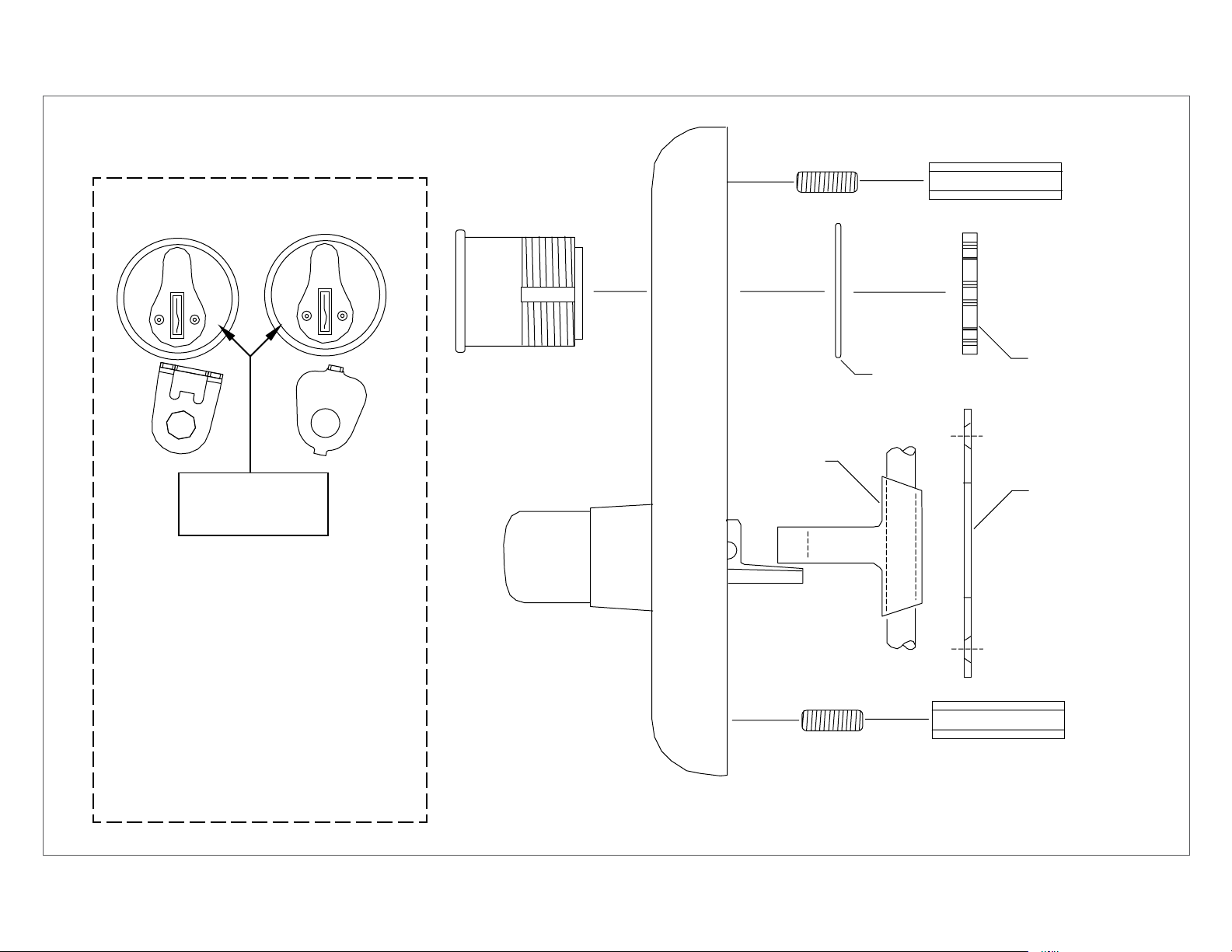
Socket set
screw
Hexagon mounting
extension
NL
Cylinder cam in
this position with
key removed
TL Function - Control remains unlocked
when key is removed
NL Function - Control relocks when key is
removed. Requires use of key to operate
TL
Mortise
cylinder
Cam
Rod
member
Cylinder nut
Cylinder locating
washer
Rub plate
For NL function replace TL cylinder plate
(std. on all controls) with NL cylinder plate
(included in polybag) replacing screw and
washer.
Note: Control must be in locked position
when installing cylinder plate.
Figure 1
Figure 2
 Loading...