

Von Duprin 376-T, 376-T-BE Installation Instructions Manual
*941148-00*
941148-00
Control for Metal Door Application
376-T, 376-T-BE
Installation Instructions
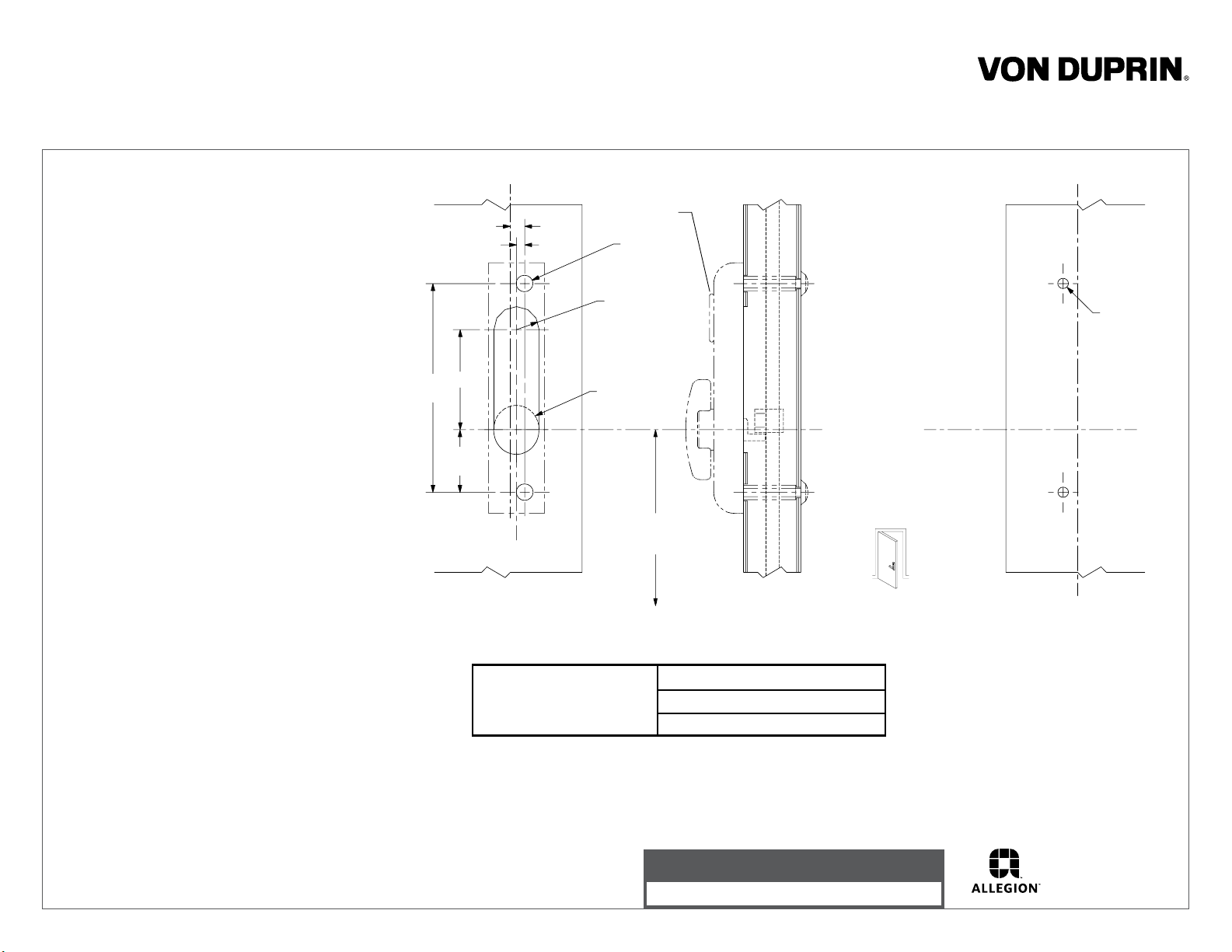
1. Prepare door for exit device. See exit
device instructions for locations of
holes, backset (line X-X), and center
lines.
2. Prepare door for control:
A. Transfer line X-X from inside (exit
device side) of door to outside
(control side) of door. Use extra
care if edge of door is beveled.
Be sure line X-X is parallel to edge
of door.
B. Locate and prepare holes as
indicated.
3. Reverse cam on back of control if reqd.
(see Figure 1 on backside of sheet).
4. Install rod member (Figure 2):
A. Slip top rod assembly in door until
bottom of rod is visible in control
cutout.
B. Slip rod member on top rod
according to handing of door. Keep
rod member visible in cutout and
lower top rod assembly until latch
release is in position on latch release
reinforcement. Slightly tighten socket
set screws in rod member to
maintain this position.
C. Install and adjust top and bottom rod
assemblies. See installation
instructions for vertical rod device.
D. Adjust member so that the bottom
surface is 1/8” below the centerline
of thumbturn. Secure rod member
by tightening socket set screws.
6-1/4”
of vertical rod
C
L
7/16”
1/4”
3”
1-7/8”
of control
C
L
Outside
face of
lock stile
For cutouts on inside face
of door see instructions in
device carton
Omit cylinder
for BE function
1/2” dia.
2 places
11/16” R, 2 places
(omit for BE)
1-3/8” dia.
(BE only)
53-1/2”
to finished
floor
5547-F Vertical Rod Exit Device
8847-F Vertical Rod Exit Device
C
L
Device Application Schedule
Corresponds to
center line of
Thumbturn
LHR shown
RHR opposite
of vertical rod
C
L
5/16” dia.
2 places
Inside
face of
lock stile
5. Complete the device installation.
6. Install cylinder if required (Figs. 3 & 4).
Insure cylinder cam is set for required
function
and replace if necessary.
7. Retract latch bolts by depressing
device crossbar.
8. Apply control and test key, control,
and device action.
Customer Service
1-877-671-7011 www.allegion.com/us
© Allegion 2014
Printed in U.S.A.
941148-00 Rev. 01/14-b
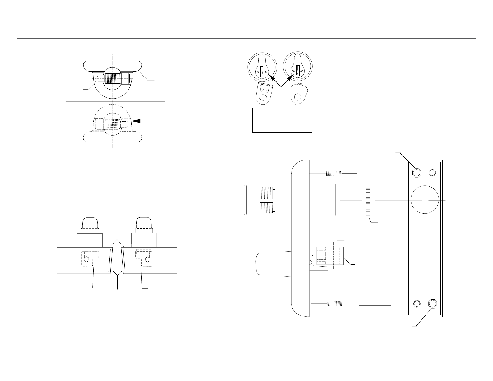
Screw
Control cam
NL
TL
TL Function - Control remains unlocked when
key is removed.
NL Function - Control relocks when key is
removed. Requires use of key to operate.
For NL function replace TL cylinder plate (std.
on all controls) with NL cylinder plate (included
in polybag) replacing screw and washer.
Correct position
for use with
5547-F and
8847-F devices
Control cam reversing procedure if required
Remove screw and rotate control cam 180
degrees to position shown and reinstall screw
Figure 1
Outside face
of door
Install rod member
in this position for
RHR door
Edge of
door
Install rod member
in this position for
LHR door
Cylinder cam in
this position with
key removed
Assemble set screw and mounting extension
Mortise
cylinder
Note: Control must be in locked position when
installing cylinder plate.
Figure 3
in this location for LHR top and bottom
Cylinder
nut
Cylinder locating
washer
Rod member
Hexagon
Socket set
screw
mounting
extension
Figure 2
Figure 4
Assemble set screw and mounting extension
in this location for RHR top and bottom
 Loading...