

Von Duprin 374-T-BE, 374-T Installation Instructions Manual

*941118-00*
941118-00
Control for Metal Door Applications
374-T & 374-T-BE
Installation Instructions
1. Prepare door for exit device. See exit device
instructions for holes and backset.
2. Transfer center line from inside (exit device side)
of door to outside (control side) of door. Use
extra care if edge of door is beveled. Be sure
center line is parallel to edge of door.
3. Locate and prepare all holes as indicated in
diagrams on other side.
4. Install exit device.
5. Make sure control cam is in position shown
in Figure 1.
6. Install cylinder, if used, in control (Figure 2).
7. Make sure control cylinder plate is correct for
desired function (NL or TL; Figure 3).
8. Disconnect top vertical rod.
9. Apply control and rub plate to door and
secure with screws (Figure 4).
10. Place rod member on top vertical rod so rod
member nger faces door and curved side of
rod member nger faces down (Figure 5).
11. Insert rod member nger into slot in door.
Reconnect top vertical rod.
12. With top latch bolt extended, slide rod
member up rod so rod member nger
touches control cam.
13. Tighten set screws in rod member with 1/8”
wrench.
hex
14. Test key, control, and exit device action.
Surface Vertical Rod Device
Application Schedule
2227
2227-F
9827/9927
9827-F/9927-F
3327/3527
3327A/3527A
3327A-F/3527A-F
Figure 1. Control cam position.
Cylinder plate
TL
NL
To change
cylinder plate,
remove screw
and washer
Figure 3. Cylinder plate.
Mortise cylinder
Control
cam
cam must be in
position shown with
key removed; if
necessary, remove
cam and install in
correct position
Countersunk
washer with
1/4-20 oval
head screw
1/4-20 x 3/8”
undercut
at head screw
1/4-20 x 7/8”
undercut at
head screw
Rub plate
Figure 4. Control and rub plate
application.
Customer Service
1-877-671-7011 www.allegion.com/us
Mortise
cylinder
Figure 2. Cylinder installation.
Rod member
Curved side of
rod member
nger faces down
Figure 5. Rod member position.
Rod
© Allegion 2014
Printed in U.S.A.
941118-00 Rev. 01/14-b
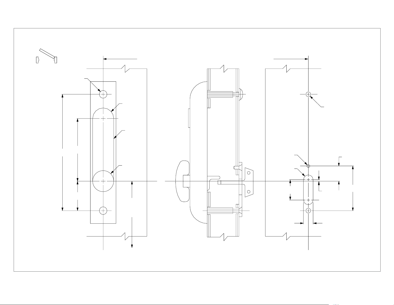
Outside
Inside
LHR shown
RHR opposite
exit device
and latch case
1/2” dia.
2 places
C
exit device
C
L
Center line exit device and latch case corresponds to
center line exit device and latch case on exit device instructions
L
and latch case
6 1/4”
3”
1 7/8”
11/16” R
2 places
Omit
slot
for BE
1-3/8” dia.
BE only
53-1/2”
to nished
oor
C
L
thumbturn
1/4-20 tap
5/16” R
1-1/4”
5/16” dia.
2 places
1/8”
5/8”
1”
2-7/8”
OUTSIDE FACE
OF LOCK STILE
For cutouts on inside face of door, see exit device instructions.
INSIDE FACE
OF LOCK STILE
 Loading...