

Von Duprin 370L, 370L-BE, 370T-BE, 370T Installation Instructions Manual
*941094-00*
Assemble set screw and hexagon mounting
941094-00
Controls for 33/35 Rim & 33/3527 Metal or Wood Doors
1. Prepare door for exit device. See exit
device instructions for locations of
holes, backset (line X-X), and center
lines.
2. Prepare door for control:
A. Transfer line X-X from inside (exit
device side) of door to outside
(control side) of door. Use extra
care if edge of door is beveled.
Be sure line X-X is parallel to edge
of door.
370T, 370L, 370T-BE, 370L-BE
extension this location for RHR top and bottom
Socket set
NL
TL
Mortise
cylinder
screw
Installation Instructions
Hexagon mounting
extension
Note: See back side of sheet for hole
preparation for metal or wood.
B. Locate and prepare holes as
indicated.
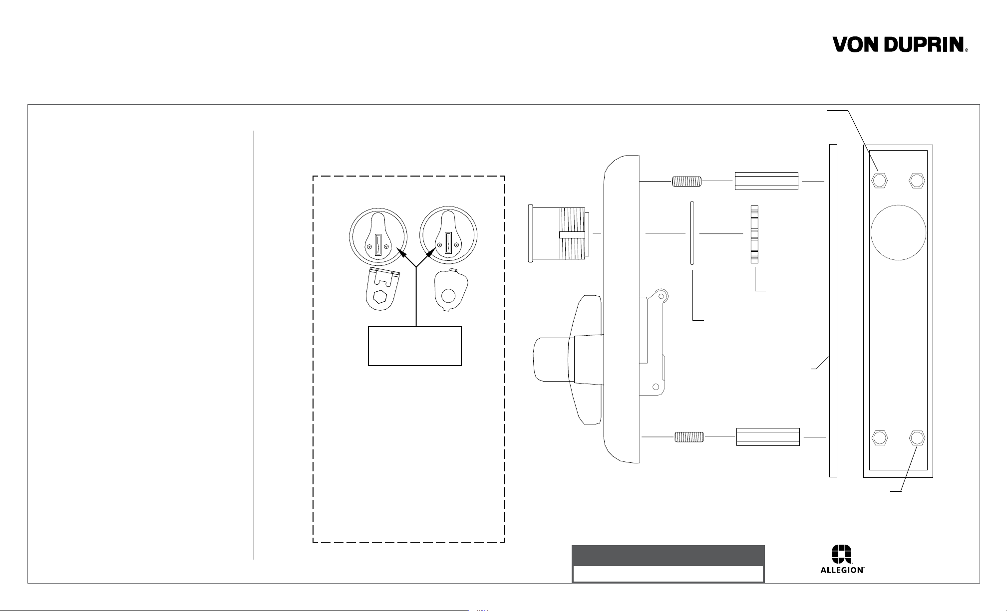
3. Install cylinder into control if required
(Figures 1 & 2). Insure cylinder cam is
set for required function and replace if
necessary.
4. Install control and exit device to door.
5. Test key, control, and device action.
941094_00(8)
BLICATION
COPY REV. A
Cylinder cam in
this position with
key removed
TL Function - Control remains unlocked
when key is removed.
NL Function - Control relocks when key is
removed. Requires use of key to operate.
For NL function replace TL cylinder plate
(std. on all controls) with NL cylinder plate
(included in polybag) replacing screw and
washer.
Note: Control must be in locked position
when installing cylinder plate.
Figure 1
Cylinder locating
washer
#10 or #11 WDA
plate for wood door
Assemble set screw and hexagon mounting
extension this location for LHR top and bottom
Figure 2
Customer Service
1-877-671-7011 www.allegion.com/us
Cylinder
nut
application
© Allegion 2014
Printed in U.S.A.
941094-00 Rev. 01/14-b
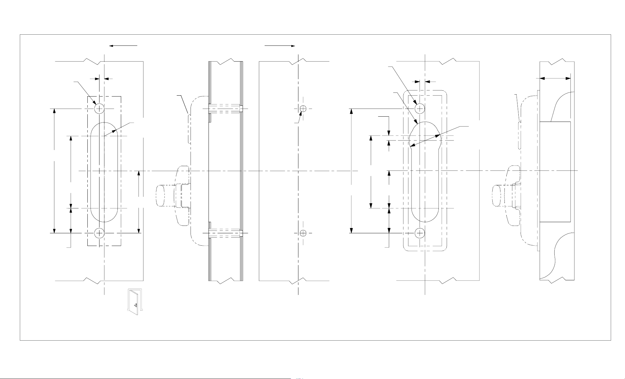
1/2” dia.
2 places
1/4”
Line X-X corresponds to line X-X on exit device instructions
Omit cylinder
for BE function
11/16” R, 2 places
5/16” dia.
2 places
XX
1/2” dia.
2 places
11/16” R, 2 places
1/4”
X
1/4”
1-9/16” for 1-3/4” door
2-1/16” for 2-1/4” door
Omit cylinder
for BE function
1-5/8” diameter
(omit for BE)
6-1/4”
1-1/4”
3-5/8”
Outside
lock stile
face of
X
3-1/8”
LHR shown
RHR opposite
Metal Door Application
Corresponds to
center line of exit
C
device on exit
L
device instructions
Inside
face of
lock stile
X
6-1/4”
3-5/8”
1-7/8”
1-1/4”
Wood Door Application
X
 Loading...