

Von Duprin 33, 3547A, 3547A-F, 3548A-F, 3548A Installation Instructions Manual
911404-00
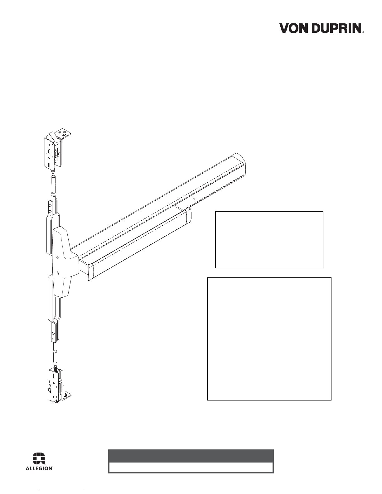
Concealed Vertical Rod Exit Device Installation Instructions
33/3547A
Devices covered by these instructions:
33/3547A and 33/3548A Concealed V ertical Rod Exit Device
33/3547A-F and 33/3548A-F Fire Concealed Vertical Rod Exit Device
CD33/3547A and CD33/3548A Concealed Vertical Rod Exit Device
EL33/3547A and EL33/3548A Concealed V ertical Rod Exit Device
Special tools needed:
#10-24 tap
Drill bits: #25, 5/16”,
13/32”, 1/2”
Index:
Screw c hart ............................2
Device installation................3-5
Adjust rods .............................6
Frame preparation.................. 7
Optional equipment................. 8
Backset information................9
Metal door templates. .......11-12
Wood door preparation....13-14
Wood door templates ......15-16
Customer Service
1-877-671-7011 www.allegion.com
© Allegion 2014
Printed in U.S.A.
911404-00 Rev. 01/14-c
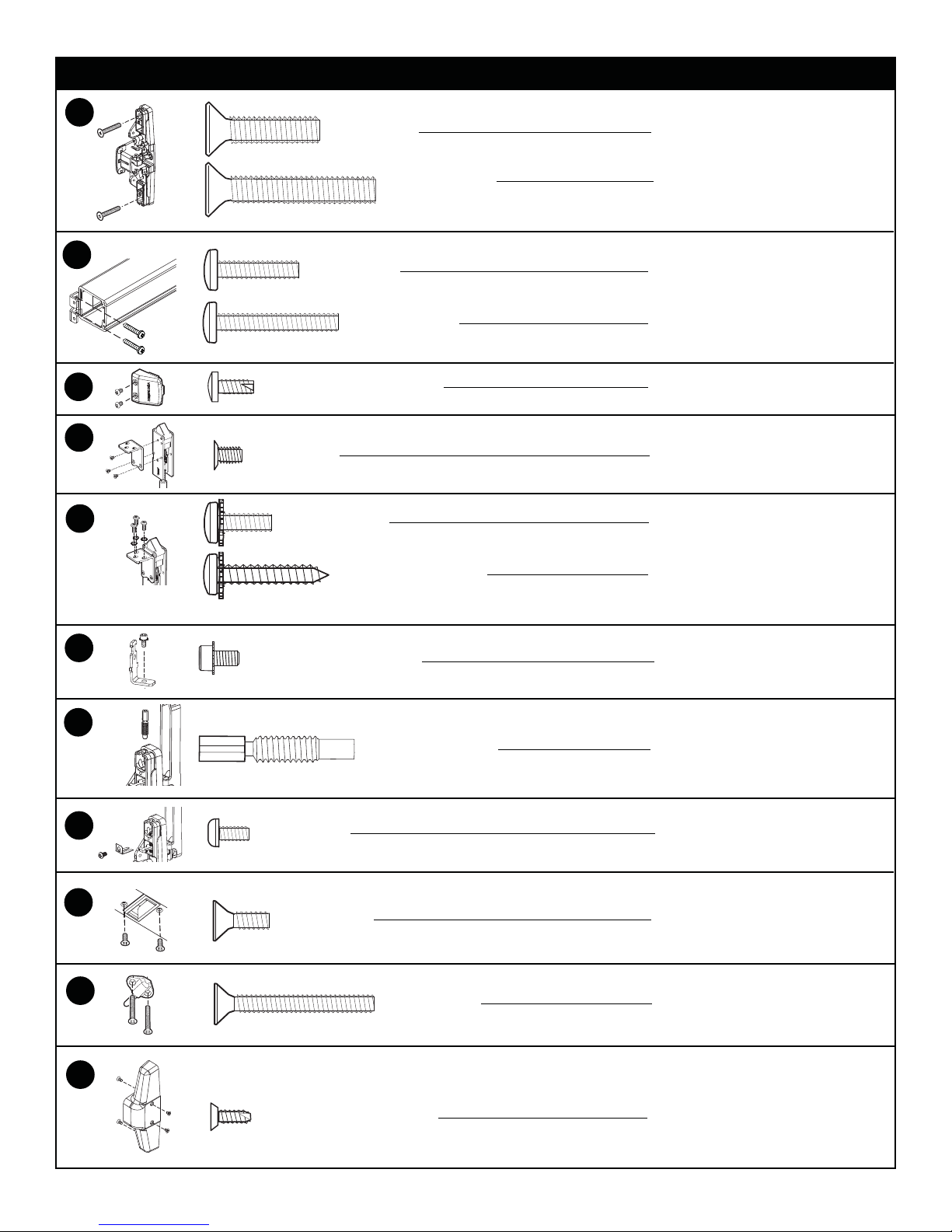
SCREW CHART
A
B
C
D
E
1/4-20 x 1”
1/4-20 x 1-1/2”
#10-24 X 3/4”
#10-24 X 1-1/8”
#10-16 X 3/8” Thread cutting
#10-32 X 1/4”
* #10-24 X 1/2”
Trim mount or sex bolts:
(1-3/4” door)
(2-1/4” door)
Surface mount or
Sex bolts (1-3/4” door)
Sex bolts ( 2-1/4” door)
End cap
Bracket to latch
Bracket to door
F
G
H
J
* #10 X 1” Wood screw
*Used with external tooth lock washer
#10-32 X 3/8” Socket head
Rod adjusting screw
#8-32 X 5/16”
Bracket to door
Rod attachment
Rod length adjustment
Retaining clip
I
#10-24 X 1/2”
#10-24 X 1-1/2”
338 Strike
Ratchet release
K
#8-18 x 3/8” Thread cutting
2
Center case cover
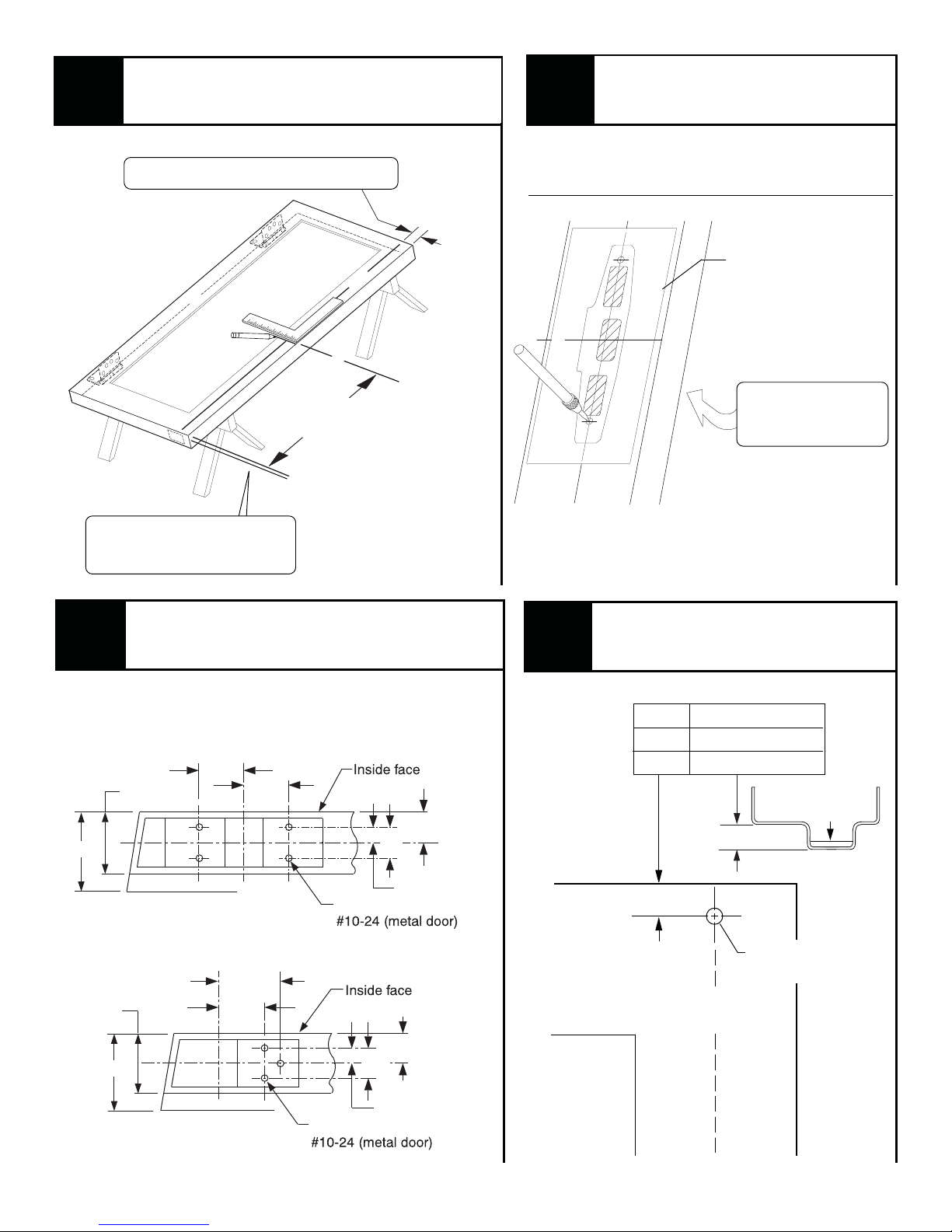
1
Draw horizontal and vertical
device center lines ( ).
See “Backset information” on page 9
C
L
Place paper device template
2
on door and prepare door.
For wood doors - See pages 13 & 14 for
special door preparation instructions.
Once hung, door should have
1/4” undercut (gap) at bottom
of door to finished floor
Prepare top and bottom of door
3
2-1/4"
for latch mounting brackets.
Latch cases
(drill top and bottom of door)
1-9/32"
1-3/4"
C
Latch case
L
1-9/32"
C
L
C
L
39-9/16”
To bottom
of door
RHR shown
(LHR opposite)
of door
7/8"
7/8"
C
L
Latch
case
C
4
Paper template
Metal - pg. 11 & 12
Wood - pg. 15 & 16
L
C
L
Prepare mounting holes and
cut-outs per template
See trim instructions
for pull side door
preparation.
RHR shown
(LHR opposite)
Drill ratchet release hole
in door.
1 1/ 16” 1/2” Stop height
13/ 16” 5/8” Stop height
15/ 16” 3/4” Stop height
Reinforcing
required
Fire device (metal door)
C
Latch case
L
1-11/16"
1-3/4"
2-1/4"
Panic device (metal door)
Panic and fire (wood door)
1-9/32"
Drill & tap
1/8" pilot drill (wood door)
7/16"
Drill & tap
1/8" pilot drill (wood door)
of door
7/8"
Latch
7/16"
C
L
case
7/8"
Drill 1/2” dia. hole
(inside face of door)
C
L
Latch
3

5
Measure to determine
length to cut device.
6
Cut device to length.
1-3/16” minimum clearance
(with end cap removed)
dengila eciveD
gnitnuom htiw
seloh
1/5
”6
Note
If 5/8” diameter wire access hole
has been predrilled in door, cut
device 5/16” from center of hole.
Prepare device for cutting
Tape
Anti-rattle clip
(remove while cutting)
Cover plate
(flush to pushbar)
Pushbar
Cut device square
Note: Device must
be cut square for
proper end cap fit
Cut device
square and
remove all burrs
7
Measure
top
length
C
L
Measure
bottom
length
Assemble rods and latches
and adjust length.
Follow white and brown instruction
cards on rods to set initial rod length
Total rod length
(with latch bolt
extended)
Subtract
1-9/16”
Subtract
1-9/16”
C
L
Total rod length
(with latch bolt
extended)
Fine tune the
total length
by threading
latches in or
out of rods
8
Rods are shipped with L-bracket attached. Insert rods
with L-bracket pointing toward lock stile. Rotate rod until
L-bracket protrudes through door cutout. If this is not
possible, remove L-bracket and re-insert rod, then
re-attach L-brackets.
NOTE: Fire devices on metal doors use
T op latch & rod Bottom latch & rod
Install rods as shown.
F
brackets on both sides of latches
L-brackets
CAUTION:
L-brackets must
be installed in
orientation shown
4
E
D
Shims used when
required for alignment
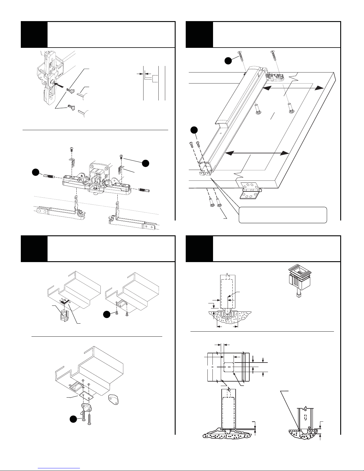
Install tailpiece guide and
9
Rotate tailpiece
guide to match
tailpiece
Place device over L- brackets and install adjusting
screws, then install retainers and locking screws
Adjusting
screws
G
attach rods to center case.
Tailpiece
guide
*Tailpiece
*Tailpiece is att ached to
trim or cylinder depending
on application
1/8”
Cut tailpiece
if needed
Door
surface
Locking
screws
H
Retainers
10
B
#425 Sex bolts
(required)
Secure device to door and
mount door to frame.
A
#325 Sex
bolts
or trim
lauqe eciveD
ot thgieh
fo mottob
no rood
dne hcae
Mark and prepare 2
mounting bracket holes
1/4” drill inside
13/32” drill outside
Bottom of door
11
Rounded
edge
Install top strike and
ratchet release.
338 Top strike
Strike
Shim
(if needed)
See “Frame Preparation”
on page 7 for holes
See “Frame Preparation” on
page 7 for cut-out and holes
Ratchet release
J
I
Spacer
(use when frame
has no door stop)
12
385-A Bottom strike
C
L
Stop
1"
2-3/4"
3/8"
1/4"
Threshold application
1-1/8"
Latch case
Install bottom strike or
prepare threshold.
C
Strike
L
385-A strike has two pieces.
Grout bottom piece into floor
and attach top piece to bottom
with screw through slot.
Note: Thresholds are not to
9/16"
3/32"
R max.
1/8"
be used with 38/3947-F
1-1/8"
Flat threshold
application
Remove material
as necessary to
accommodate
latch bolt throw
5/8"
5/8"
5
 Loading...