

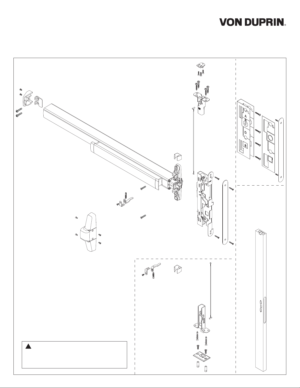
Von Duprin 3550AWDC, 3350AWDC Installation Instructions Manual
24739476
33/3550AWDC
Installation Instructions
Fire-Rated
Devices
include these
additional
components
1-Point
Latch
(LBL)
2-Point
Latch
includes these
additional
parts
Metal Edge
Wrap required
for 60 and
90-minute
applications
!
NOTE: If door does not have a cutout for
cabling inside lock stile, door must be
routed. Refer to 33/3550AWDC wood
door template #24731408.
1 OVERVIEW AND DOOR PREPARATION
33/3550AWDC
Instead of traditional rods, concealed vertical cables are utilized, making use of a proven technology
that enables quick installation and allows for easy maintenance. Simplified sizing, ease of adjustment
and greater door integrity make the Wood Door Concealed exit device a more secure solution, without
the complexity associated with traditional concealed systems. Another key benefit of the system is the
ability to make adjustments to the system by simply removing the scalp plate from the edge of the
door.
If you have any questions or comments please visit the resources below or give us a call so we can
help get you on your way. Thank you for your continued support of Von Duprin.
Technical Support hot line: 877-671-7011
Scan this QR code or visit us online at kc.allegion.com to access the
Allegion Knowledge Center.
Need a reader for your phone?
For iPhone: QR Reader
For Android: QR Barcode Scanner
TABLE OF CONTENTS
INSTALLATION
1.
Overview and Door Preparation pg 2-3
2.
Fire Barrier pg 4-5
3.
Latch Installation pg 6
4.
Cable Installation pg 7
5.
Device Installation pg 8-9
ADJUSTMENT
6.
Device Adjustment pg 10-11
7.
Strikes and Fire Pin pg 12-13
8.
Bottom Latchbolt Clearance pg 14
9.
Top Strike and Covers pg 15
10.
Troubleshooting pg 16
2
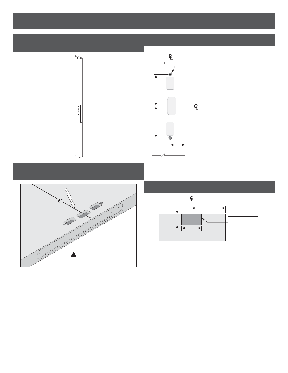
1 (continued)
1a For 60 and 90-minute applications, install metal edge
wrap.
1b With door laying fl at, draw horizontal device center
C
line (
).
L
1c If necessary, prepare center case mounting holes.
Device
Sex bolts Ø ¹³⁄₃₂" thru (Pre-prepped at factory)
Trim Ø ¹⁄₂" thru (Enlarge existing holes)
(2 places)
3¹⁄₈"
Device
3¹⁄₈"
1¹⁄₂" Backset
RHR shown
(LHR opposite)
(LHR opposite)
!
NOTE:
Centerline is
predetermined by cutout.
RHR shown
1d If necessary, prepare door for top strike cutout.
Latch
2"
Cut out material
this side only
1³⁄₁₆"
⁵⁄₈"
Push side of door, RHR shown
3
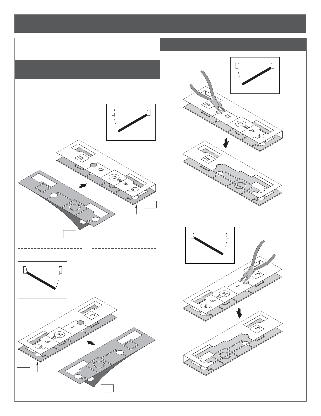
2 FIRE BARRIER
I Fire application only
I Fire components must be installed to maintain fi re rating
of opening.
2a Peel adhesive backing from intumescent and apply to
trim side of fi re barrier.
2b Remove appropriate knockouts for device and trim.
I Intumescent must be properly aligned before exposed
adhesive contacts fi re barrier. Adhesive is permanent and
not repositionable.
RHR
Trim Side
a-1
RHR
Exit Only (EO) shown
a-2
a-2
4
OR
LHR
LHR
Exit Only (EO) shown
Trim Side
a-1
2 (continued)
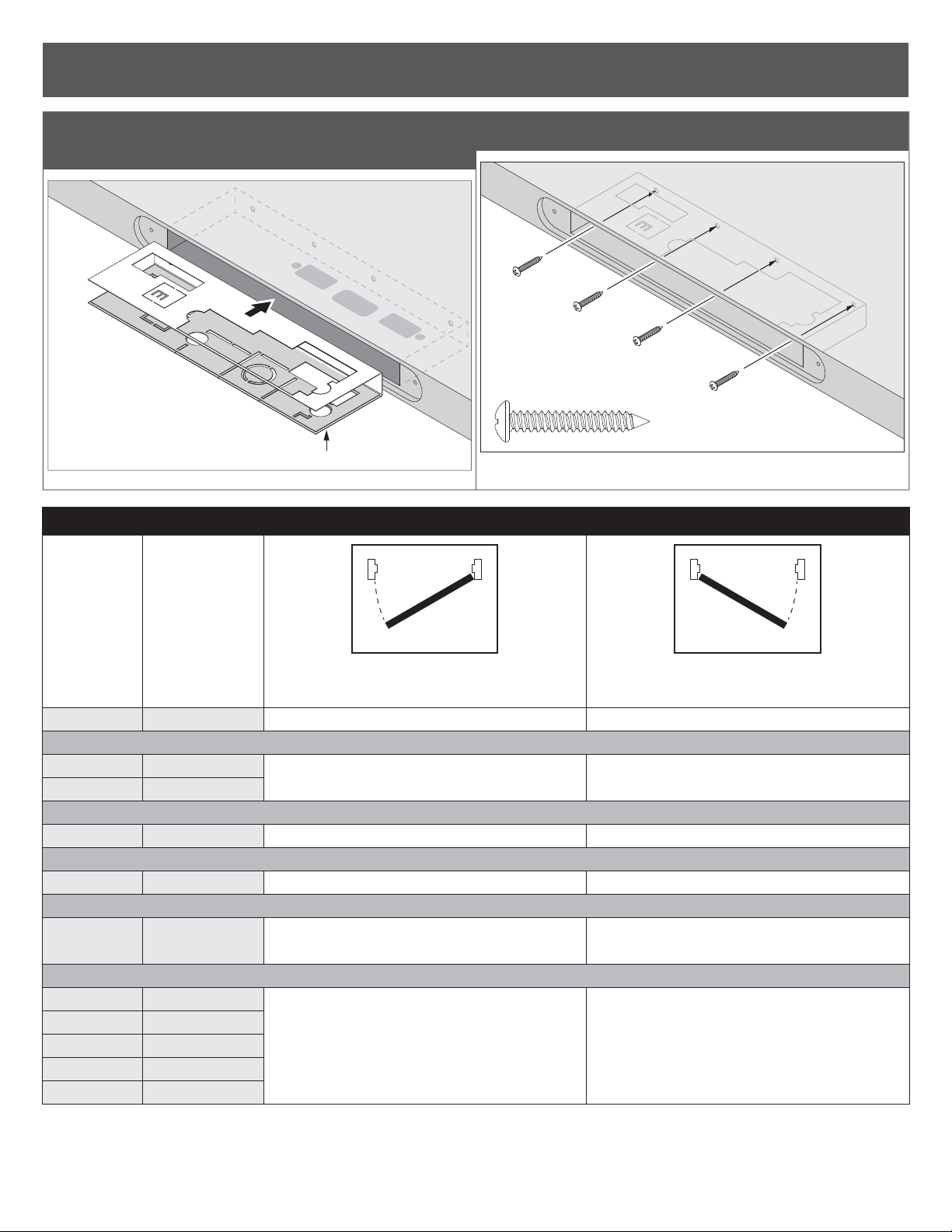
2c With fi re barrier in correct orientation, slide barrier into
door pocket.
RHR shown
Trim Side
FIRE BARRIER KNOCKOUT TABLE
2d Secure fi re barrier to inside of pocket with 4 screws.
Trim
Model
Exit Only
386
386
388
550
392-6
360
360
360
360
360
Trim
Function
EO
DT
NL
NL
DT
-
L
L-BE
L-DT
T
T-BE
RHR LHR
Right Hand Reverse (RHR)
Remove the knockouts listed below
A B C D
A B C D H
A B C D G H
A B C D E J
A B C D
(If mounted below, remove E, J)
A B C D F G H
Left Hand Reverse (LHR)
Remove the knockouts listed below
F G H I
C F G H I
B C F G H I
E F G H I J
F G H I
(If mounted below, remove E, J)
A B C F G H I
5
 Loading...