

Von Duprin 33/3527A, CD33/3527A, 33/3527A-F, EL33/3527A, SS33/3527A Installation Instructions Manual
*911403-00*
911403-00
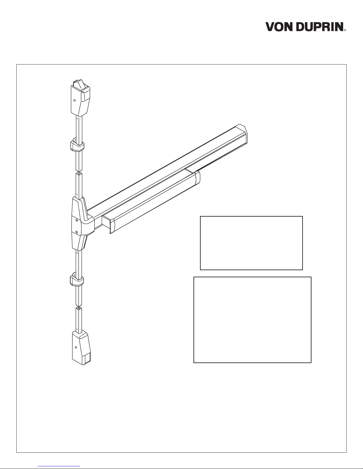
Surface Vertical Rod Exit Device
33/3527A
Installation Instructions
Devices covered by these instructions:
33/3527A Surface Vertical Rod Exit Device
33/3527A-F (Fire) Surface Vertical Rod Exit Device
CD33/3527A Surface Vertical Rod Exit Device
EL33/3527A Surface Vertical Rod Exit Device
SS33/3527A Surface Vertical Rod Exit Device
Special tools needed:
#10-24 tap
Drill bits: #25, 1/8”, 1/4”,
5/16”, 13/32”
Index:
• Screw chart ............................ 2
• Device installation................ 3-6
• Cut top rod.............................. 7
• Install rod extension................. 7
• Optional equipment................. 8
• Templates .......................... 9-14
Please give these instructions to building owner after device is installed

SCREW CHART
A
B
C
D
1/4-20 x 1”
1/4-20 x 1-1/2”
#10-24 X 3/4”
#10-24 X 1-1/8”
#10-16 X 3/8” Thread cutting
1/4-20 X 3/4”
1/4-20 X 1-1/4”
Trim mount or sex bolts:
(1-3/4” door)
(2-1/4” door)
Surface mount or
Sex bolts (1-3/4” door)
Sex bolts (2-1/4” door)
End cap
1-3/4” door
2-1/4” door
E
F
G
H
I
J
#10-24 X 3/4”
#8-32 X 1/4”
#10-12 x 10-24 x 1-1/4” combination
#10-24 X 1-1/4” wood screw
#10-12 x 10-24 x 1-1/4” combination
#10-12 x 10-24 x 1-1/4” combination
#8-16 x 8-32 x 1” combination
Metal or wood frame
Metal frame
Wood frame
Metal or wood frame
Variable floor surfaces
Metal or wood door
Latch covers
K
#8-18 x 3/8” thread cutting
2
Center case cover
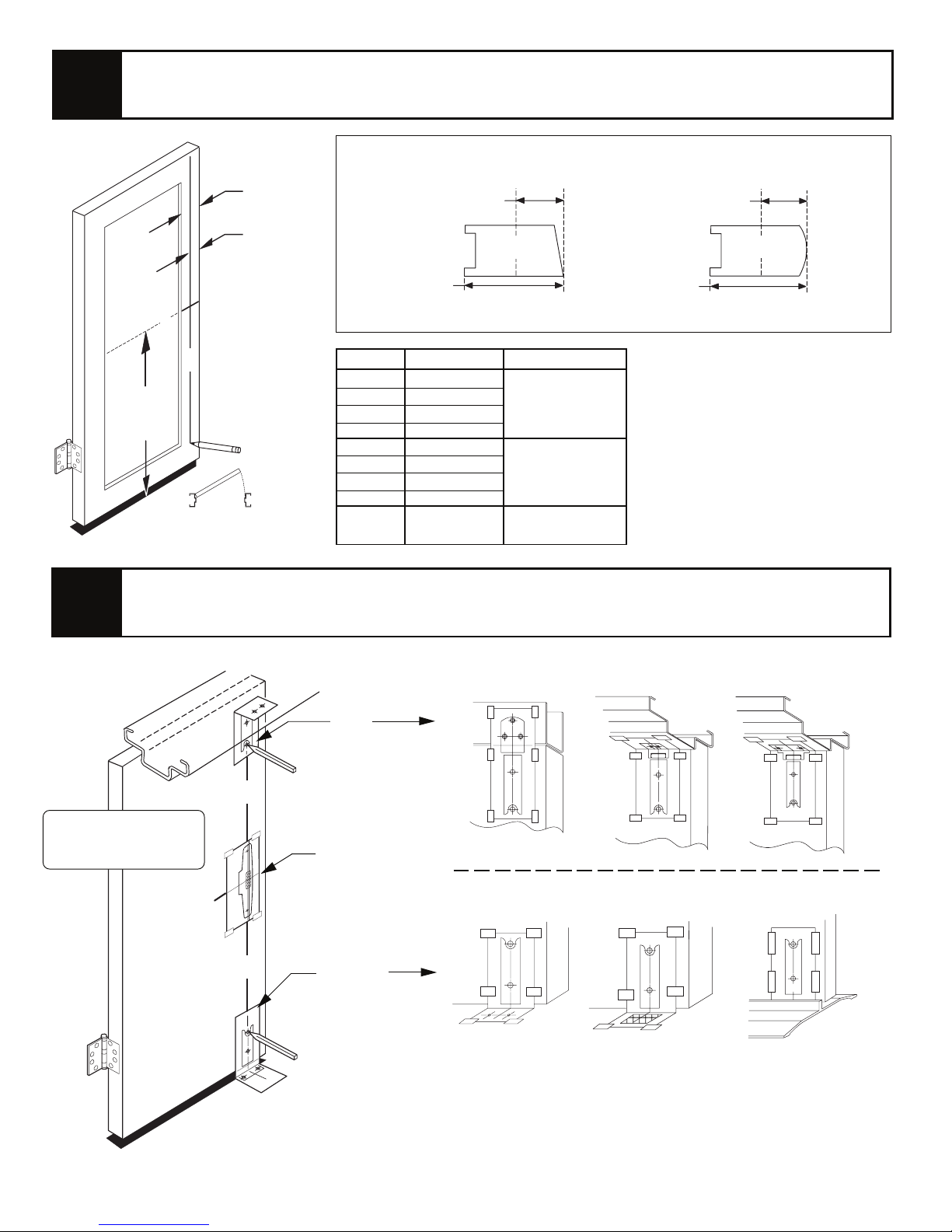
1
Figure backset and draw device center lines ( ) on door as shown.
Backset is measured from outer edge of door as shown. Minimum stile is less
Stile
width
glass stop (rectangular glass stop is recommended for stiles less than 2-1/8”)
Backset
C
L
Backset
2
C
L
39-13/16”
to finished
floor
Backset
C
L
RHR shown
(LHR opposite)
Backset
1-3/16”
1-1/2”
1-7/8”
2-1/2”
1-11/32”
1-1/2”
1-7/8”
2-1/2”
2-7/32”
Min. stile
Min. stile
2”- 2-3/4”
2-3/4”- 3-3/4”
3-3/4”- 5”
5” to flush
2”- 2-3/4”
2-3/4”- 3-3/4”
3-3/4”- 5”
5” to flush
3” min.
C
L
Beveled edge door
Application
Two vertical
rod devices
Single door
Vertical rod
and rim device
Min. stile
Rounded edge door
Note: For 299/299F top strike use
minimum backsets shown below.
Double doors: 1-3/8” min. backset
Single door: 1-7/8” min. backset
C
L
2-3/16” min. stile
2-11/16” min. stile
Tape templates to door and prepare door and frame per templates.
260U strike
266 strike
*299/299F strike
See trim instructions
for pull side door
preparation.
C
Top
template
(page 11 & 12)
C
L
Device
template
(page 15 & 16)
L
C
L
Bottom
248L-4 strike 304L strike
Latch track
template
(page 13 & 14)
*For 299/299F top strike use minimum backsets shown below.
Double doors: 1-3/8” min. backset, 2-3/16” min. stile
Single door: 1-7/8” min. backset, 2-11/16” min. stile
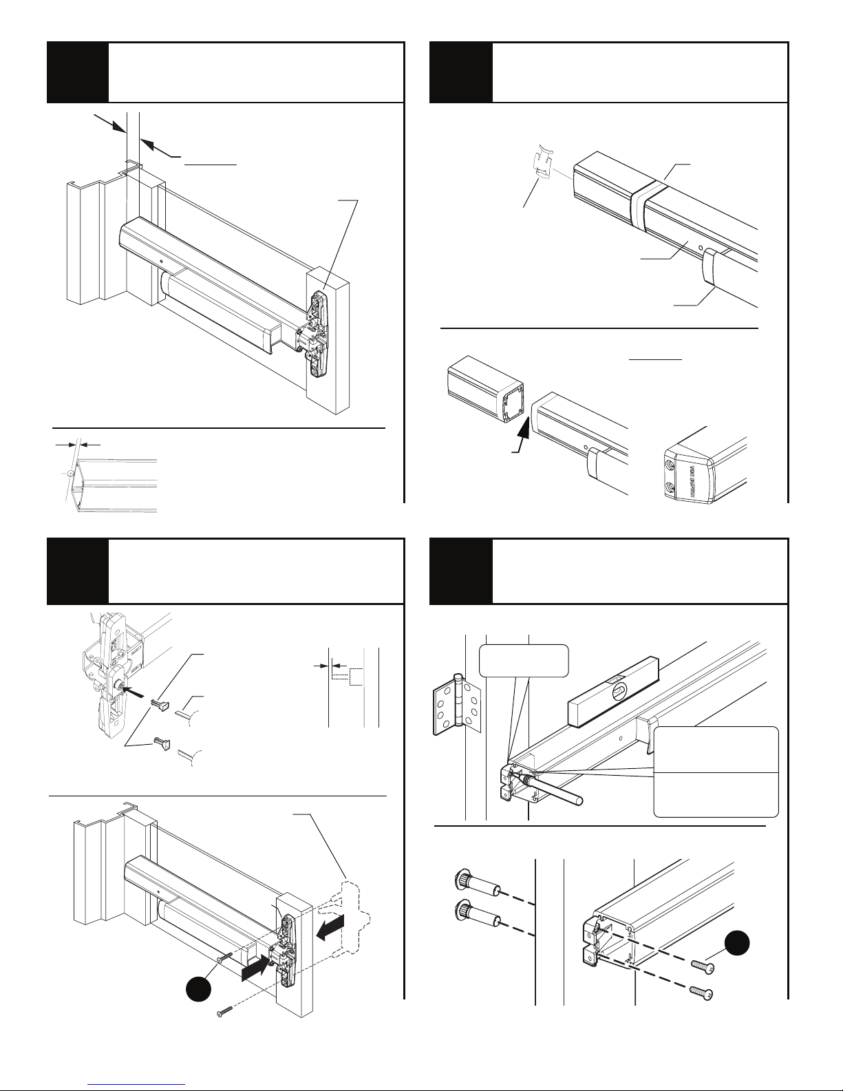
3
3
Measure to determine
length to cut device.
4
Cut device to length.
Prepare device for cutting
5
1-3/16” minimum clearance
(with end cap removed)
dengila eciveD
gnitnuom htiw
seloh
”61/5
Note
If 5/8” diameter wire access hole
has been predrilled in door, cut
device 5/16” from center of hole.
Install tailpiece guide and trim
(or sex bolts) and secure
device
center case to door.
Anti-rattle clip
(remove while cutting)
Cut device
square and
remove all burrs
Install hinge stile mounting
6
bracket.
Tape
Cover plate
(flush to pushbar)
Pushbar
Cut device square
Note: Device must
be cut square for
proper end cap fit
Rotate tailpiece
guide to match
tailpiece
See page 2 for
Screw Chart
Tailpiece
guide
*Tailpiece
* Tailpiece is attached to
trim or cylinder depending
on application
Trim or
#325 sex bolts
(required)
Center
case
1/8”
A
Cut tailpiece
if needed
Door
surface
Mark and prepare 2 mounting holes
Mounting
bracket flush
Level device
1/4” drill inside
13/32” drill outside
MetalWood
13/32” drill thru
Secure mounting bracket
#425
Sex bolts
(required)
B
4
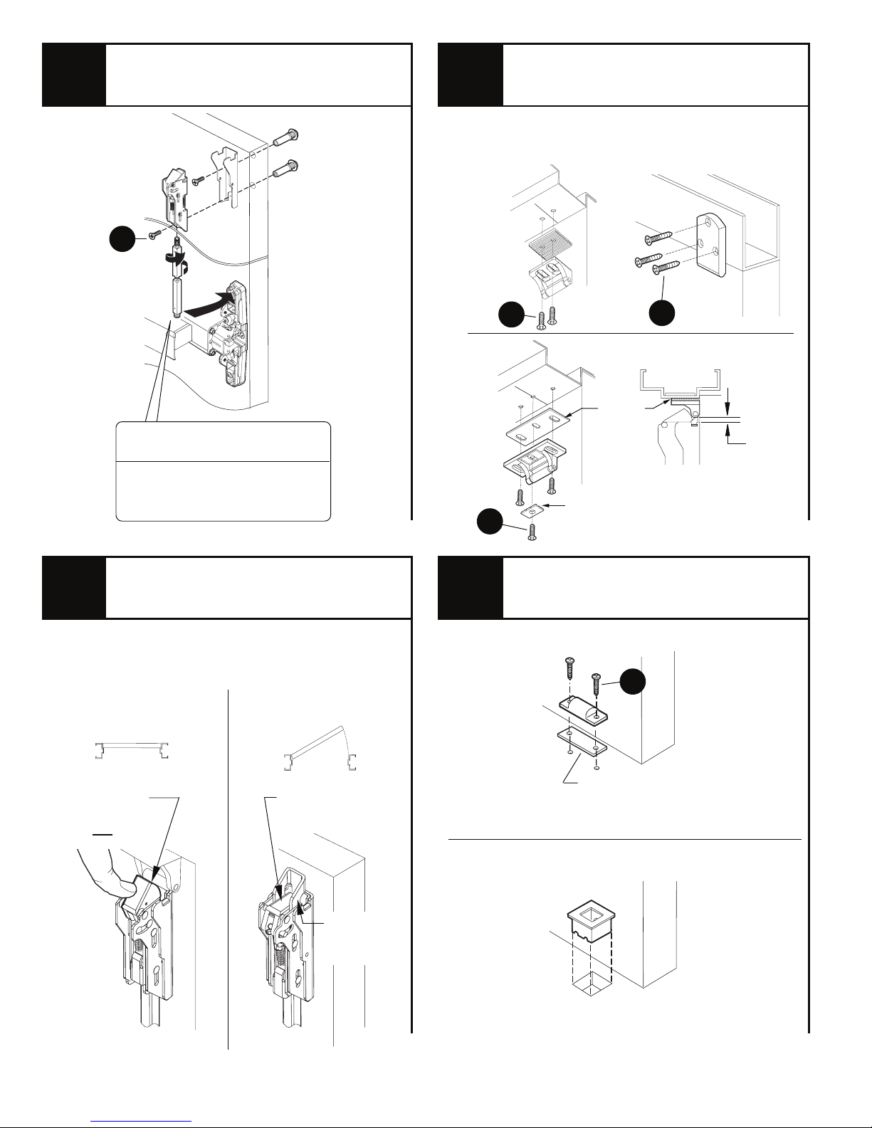
7
Install top latch and rod.
8
Install top strike.
Top
latch
D
Top rod
(longer of
the two)
If top rod is too long, see “Cut
top rod” on page 7
If top rod is too short, see
“Install rod extension”
on page 7
#
325 sex bolts
(required)
266 strike
For panic device
application only
E
E
F
For panic device
application only
G
299/299F strike
Shim
to 3/16”
as shown
Strike plate
(299 only)
260U strike
3/16”
Adjust top rod until latch
9
Adjust rod by threading rod into latch clockwise
to shorten, or counterclockwise to lengthen.
Latch bolt
deadlocked
not push in)
(will
bolt acts as shown.
With door
closed:
With door
open:
Latch bolt
stays retracted
Release
trigger
extended
10
Install bottom strike,
latch, and rod.
248L-4 strike
Use 248L-4 strike
H
Shim
(as needed to
engage latch)
304L strike
for panic device
application only.
Use 304L for
fire doors
Grout strike
into floor
5
 Loading...