

Von Duprin 33, 3549A Installation Instructions Manual
FOR DEVICES SOLD
PRIOR TO
33/3549A
4-14-14
CS 33/3549A
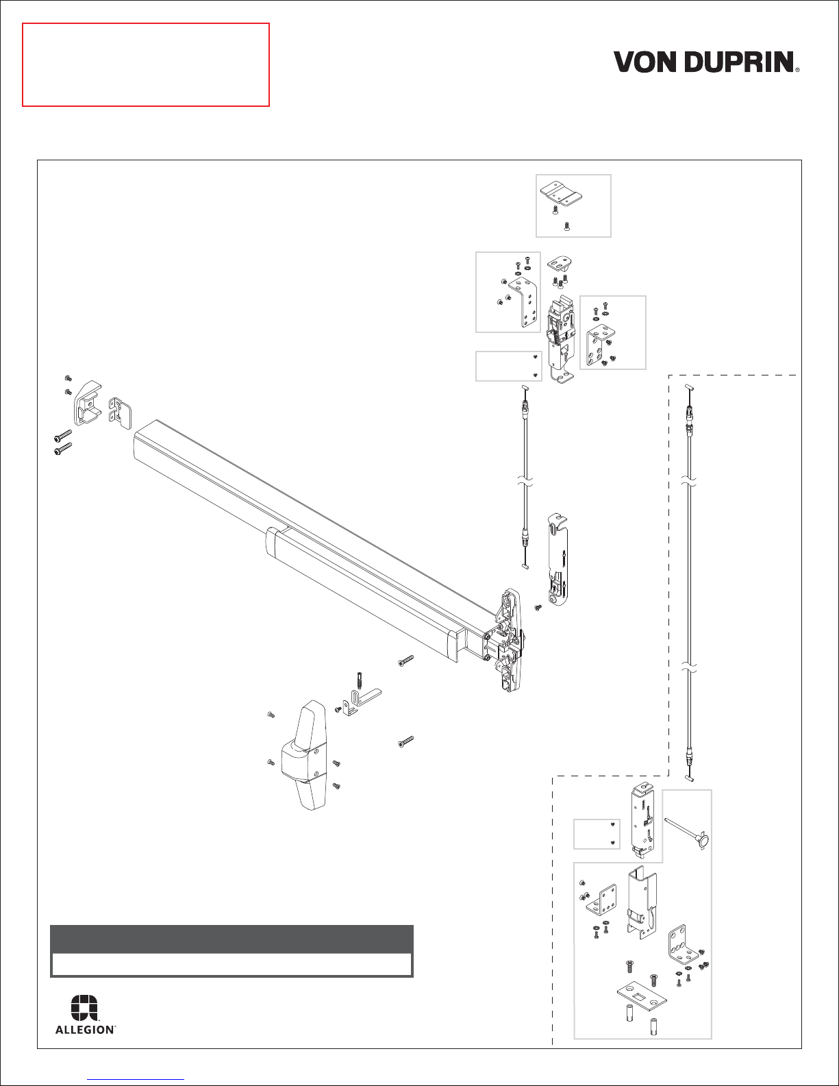
This instruction covers new installation of the 33/3549A
concealed vertical device for aluminum and hollow metal
doors.
Also covered is the CS 33/3549A retrofit cabling system
for converting 33/3547A Series to 33/3549A Series
(compatible with models 33/3547A, 33/3547A-F,
33/3547A-LBR, and 33/3547A-F-LBR).
1-Point
Latch
(LBL)
Installation Instructions
RF
HM
HM
AL
2-Point
Latch
includes
these
additional
parts
AL
= for Aluminum Door applications
HM
= for Hollow Metal Door applications
RF
= for Hollow Metal Door Retrofit applications
Customer Service
1-877-671-7011 www.allegion.com/us
© Allegion 2014
Printed in U.S.A.
24795379 Rev. 04/14-a
HM
AL

1
Identify Cables and Locations.
(if not preinstalled in door)
A
For easy identification,
each cable is labeled
with part number and
location.
2
Install Cable(s).
a. Position red cable end to clip on center slide
b. Pull cable into clip to snap it into place
B
a
clip
b
Door Opening
Height
6' 8"
7' 0"
8' 0"
9' 0"
10' 0"
Red
!
IMPORTANT:
Ensure cable end is
fully seated in clip
!
NOTE: For retrofit installations,
begin at Step 5.
CABLE IDENTIFICATION (STANDARD SIZES)
HOLLOW METAL AND
WIDE STILE ALUMINUM DOORS
A
Top Cable (Red)
23925761
23925647
23925522 23925522
23925407
Bottom Cable (White)
BB
Top Cable (Red)
23926173
23926058 23926058
23925936
23925811
NARROW STILE
ALUMINUM DOORS
A
Bottom Cable (White)
23925803
23925761
23925647
23925407
For 2-Point Latch Only
e. There is an adjuster on one end of the white cable. Install this end to the
remaining top latch position (marked as white)
!
Ensure cable end is
fully seated in clip
White
adjuster
e
2392621523925795 23926207
23926173
23925936
23925811
IMPORTANT:
c. Push cable snap against center slide to secure cable
cable snap
c
d. In the same way, install opposite end of red cable to top latch in the
position marked red
d
CABLE REMOVAL
A cable removal tool has been provided. Slot in tool fits over cable,
holding tabs down. Pull on cable snap to loosen cable for removal.
f. Install opposite end of white cable to bottom latch
f
cable
slot
snap
a
b
2

3
Determine if Bottom Latch Retraction Adjustment is
Necessary.
For 2-Point Latch Only
a. Flex the cable into an L-shape as shown to simulate the installed
condition of the latches.
4
Adjust Bottom Latch Retraction (if necessary).
For 2-Point Latch Only
NOTE: Adjustment must be made while the top
!
latch is in the hold-open position, with cable
flexed into an L-shape to simulate the installed
condition of the latches.
b. To determine whether an adjustment is required, actuate the top
latch to the hold-open position by pressing down on the connecting
rod. Bottom latch should retract to within ¹⁄₁₆" of flush. If it does not,
an adjustment is necessary.
These (3) hex
components
are used to
make the
adjustment.
a. While holding the snap-fitting
with a ³⁄₈" wrench, use a 10mm
wrench to break loose the lock
nut.
³⁄₈"
lock nut
top latch
10mm
conduit cap
c. While holding the conduit cap
snap-fitting
locknut
with a ³⁄₈" wrench, use a 10mm
wrench to turn the locknut in a
clockwise direction to close the
gap between the lock nut and
snap-fitting. Stop when the gap
is closed and the snap-fitting
begins to turn with the locknut.
10mm
top latch
(hold-open
position)
press
bottom latch
(retracted)
If no adjustment is
needed, proceed
to Step 5.
¹⁄₁₆"
flush
b. While holding the lock nut in
place, rotate the barrel of the
snap-fitting clockwise by hand
until the bottom latch is
retracted to within ¹⁄₁₆" of flush.
snap-fitting
flush
¹⁄₁₆"
bottom latch
(retracted)
³⁄₈"
conduit
cap
d. While holding the snap-fitting
with a ³⁄₈" wrench, continue to
tighten the locknut until it is
secure.
10mm
³⁄₈"
3
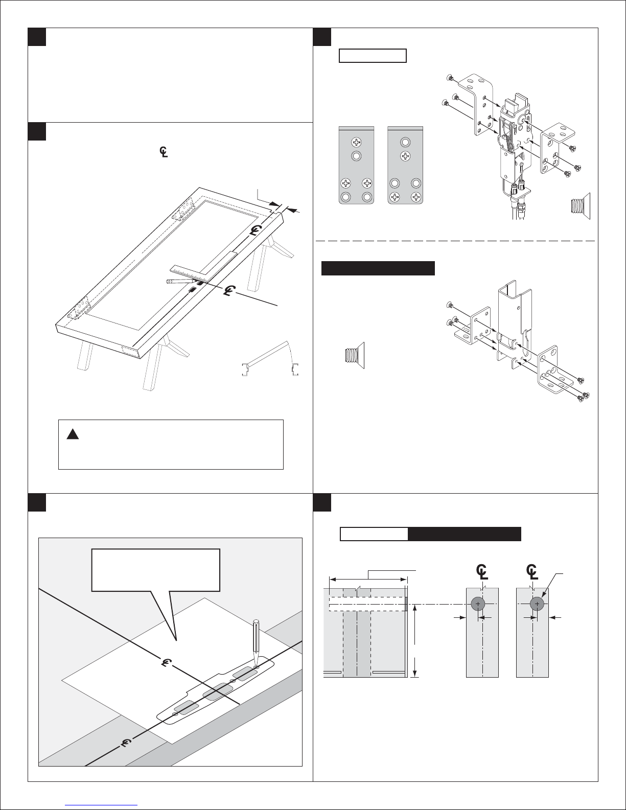
5
If Retrofit Installation
a. Remove device
from existing
door.
6
With Door Laying Flat, Draw Horizontal and Vertical
b. Remove and
discard existing
door.
c. Remove and
discard existing
strikes.
Device Center Lines ( ).
See template
for Backset
8
Assemble Latch Mounting Brackets.
Hollow Metal
Top
1/4"3/4"
3/4"
1/4"
Top Door Channel
3/4"
1/4"
Bottom
For 2-Point Latch Only
³⁄₄" mounting
shown
RHR shown
(LHR opposite)
!
NOTE: Centerlines are predetermined by cutout. If no
cutout exists, refer to templates at the back of this
instruction to determine centerlines.
7
Align Paper Template to Mark and Prepare Door, if
Required.
See pages 11 and 12
for paper templates.
9
Prepare Access Hole for Bottom Latch Adjustment
Pin.
Hollow Metal
For 2-Point Latch Only
Door Door
4¹⁄₄" depth
clearance
required
⁵⁄₈" from
push side
of door
3¹⁵⁄₁₆"
³⁄₄" Dia.
hole
⁵⁄₈" from
push
side of
door
RHR shown
(LHR opposite)
Bottom of Door Door Edge
RHR
Door Edge
LHR
4
 Loading...