

Von Berg Bioset 9000E User manual


TABLE OF CONTENTS
Table of Contents
1 GENERAL .................................................................................. 1- 1
1. 1 Application............................................................................................1-1
1.2 Unit design............................................................................................1-1
2 PATIENT’S AND UNITS SAFETY............................................2-1
3 OPERA TING ELEMENTS..........................................................3-1
3.1 V i e w .....................................................................................................3-1
3.2 Keypad and key functions ....................................................................3-2
4 PUTTING INTO OPERATION ...................................................4-1
4.1 Insertion of recording paper.................................................................. 4-1
4.2 Application of electrodes ...................................................................... 4-1
4.2.1 Resti ng ECG......................................................................................... 4-1
4.2.2 Exercise ECG ....................................................................................... 4-3
4.3 Switching the unit on and off................................................................ 4-4
4.3.1 Mains operation ....................................................................................4-4
4.3.2 Battery operation ..................................................................................4-4
4.3.3 Switching ON and OFF ........................................................................ 4-4
5 ECG RECORDING .....................................................................5-1
5.1 Recording in manual mode ................................................................... 5-1
5.2 Recording in automatic mode ............................................................... 5-2
5.3 Recording with ergometry (remote start) ..............................................5-3
5.4 Recording a test ECG .......................................................................... 5-4
6 ECG MEASUREMENT AND INTERPRET A TION....................6-1
6.1 Measurement and interpretation ...........................................................6-1
6.2 Analysis results .....................................................................................6-2
7 UNIT SETUP...............................................................................7-1
8 INTERF ACES .............................................................................8-1
8.1 Analogous (1V) outlets ......................................................................... 8-1
8.2 Serial interface RS 232 .........................................................................8-1
9 TECHNICAL CHARACTERISTICS ..........................................9-1
9.1 General data ......................................................................................... 9-1
9.2 Recording unit ......................................................................................9-1
9.3 ECG section ......................................................................................... 9-2
9.4 Operation section.................................................................................. 9-3
9.5 Standard interfaces ............................................................................... 9-3
9.6 ECG analysis software ......................................................................... 9-4
10 CLEANING, DISINFECTION ....................................................10-1
11 MAINTENANCE, CHECKS.......................................................11-1
12 ENVIRONMENT AL PROTECTION/WASTE REMOV AL.........12-1
Annex 1 Unit symbols used
Annex 2 Advice on handling thermoreactive recording paper
Unit No.
0-1

MANUFACTURER´S LIABILITY
Manufacturer’s Liability
The manufacturer can only be made liable for possible effects concerning safety , reliability,
and performance of the unit, if
- installation works, extensions, resettings, changes, or repair works are executed by persons authorised by
the manufacturer;
- the electric installation of the room meets the requirements of the applicable regulations;
- the unit is applied in accordance with this operating manual.
This unit may only be operated with accessories and other parts supplied from us. Otherwise, it may come to
defects or false information.
0-2

APPLICATION
1 General
1.1 Application
BIOSET 9000E is a 6/12-channel electrocardiograph.
As a variant, the unit can be supplied with automatic ECG measurement function or automatic measurement/
interpretation using the HES analysis program by the Medizinische Hochschule Hanover.
If desired, it is also possible to unlock the ECG measurement/interpretation function in the client’s house.
BIOSET 9000E is foreseen for ECG recording in the ambulant practice and clinical routine.
Owing to its small dimensions, low weight, and possible battery operation it is suitable for
home visits and emergency medicine.
1.2 Unit Design
BIOSET 9000E is a compact unit with horizontal upper side.
The casing consists of two plastic shells with easy-to-clean surface. The lower part is the chassis which
includes the most significant components.
The main components of BIOSET 9000E are:
Lower casing part with
- circuit board with the entire electronic system
- recording unit as a separate module
Upper casing part with
- keypad including LEDs
The power pack is inside the unit; it is a plug-in type and can easily be exchanged.
The software is installed in a flash ROM memory. Through the RS 232 interface, it can easily be updated.
1-1

PATIENT`S AND UNIT`S SAFETY
2 Patient’s and Unit’ s Safety
BIOSET 9000 is in accordance with the Medical Products Act (MPG) and the “Directive 93/42/EEC
on Medical Devices (MDD)” and meets thus the safety requirements as per EN 60 601-1 (IEC 601-1)
and the anti-interference requirements as per EN 60 601-1-2 (EMC act).
According to the above guideline, the unit falls under the risk class IIa.
In order to protect both patient and personal, the unit must be grounded.
The unit complies with the protection class I. This way, it will be grounded through the protective conductor. Any usage of mains-connecting facilities which can cause the protective conductor to be interrupted is
forbidden.
The unit is defibrillation- proof, provided, the patient’s cable supplied with the accessories is used. During
defibrillation, one must not touch the patient, the equipment or the bed.
In case that the unit is used for ECG acquisition from patients with heat pacemakers, or if a further electrical simulator is used simultaneously, the is no kind of endangering. Naturally, simulator should be used in a
reasonable distance from the electrodes. In case of doubt, the patient should be disconnected from the electrocardiograph.
The unit should be operated inside rooms protected against vibrations and corrosive gases, and should not
be exposed to direct sun radiation or heat from other sources. The unit works at ambient temperatures of
10° C ... 40° C.
For the safe operation to obtain, keep the unit free from condensation water. In order to prevent that, make
the unit acclimate after relevant temperature alterations.
Once temperature and atmospheric humidity have compensated, the unit can be operated.
The unit is not intended to be run inside explosion-hazardous locations. If inflammable gas mixtures (e.g.
ether) are present, explosion hazard cannot be excluded.
Connection of a PC to the RS232 interface requires the fulfilment of the standards by both PC and peripheral units. As per the IEC 601-1-1 (compound operation of electrical, medical equipment and electrical, nonmedical equipment), the PC set must be located in a distance of ³ 1.5 m to the patient.
In case that the unit’s instruction manual does not indicate whether a certain compound operation or coupling with other equipment is possible any kind of danger, a relevant information must be obtained from the
manufacturer/supplier, or from an expert, in order to ensure that the total safety of all included units is not
affected.
A situation of danger might arise, if more than one unit are connected to the patient, or at the electrocardiograph, and the sum of all discharge currents would be beyond the permissible limits.
The units are allowed to be used only by persons, who due to their education, knowledge, and practical experience can guarantee proper handling and who have been made familiar with the unit in consideration of
the operating manual.
Only those persons who due to their knowledge and practical experience are fit for briefing people on the
handling of the device are allowed to instruct them.
F This operating manual is part of the electrocardiograph and must always be on hand. Strict observa-
tion of it is precondition for proper use, on which both patient’s and operating personnel’ s safety are
depending.
2-1
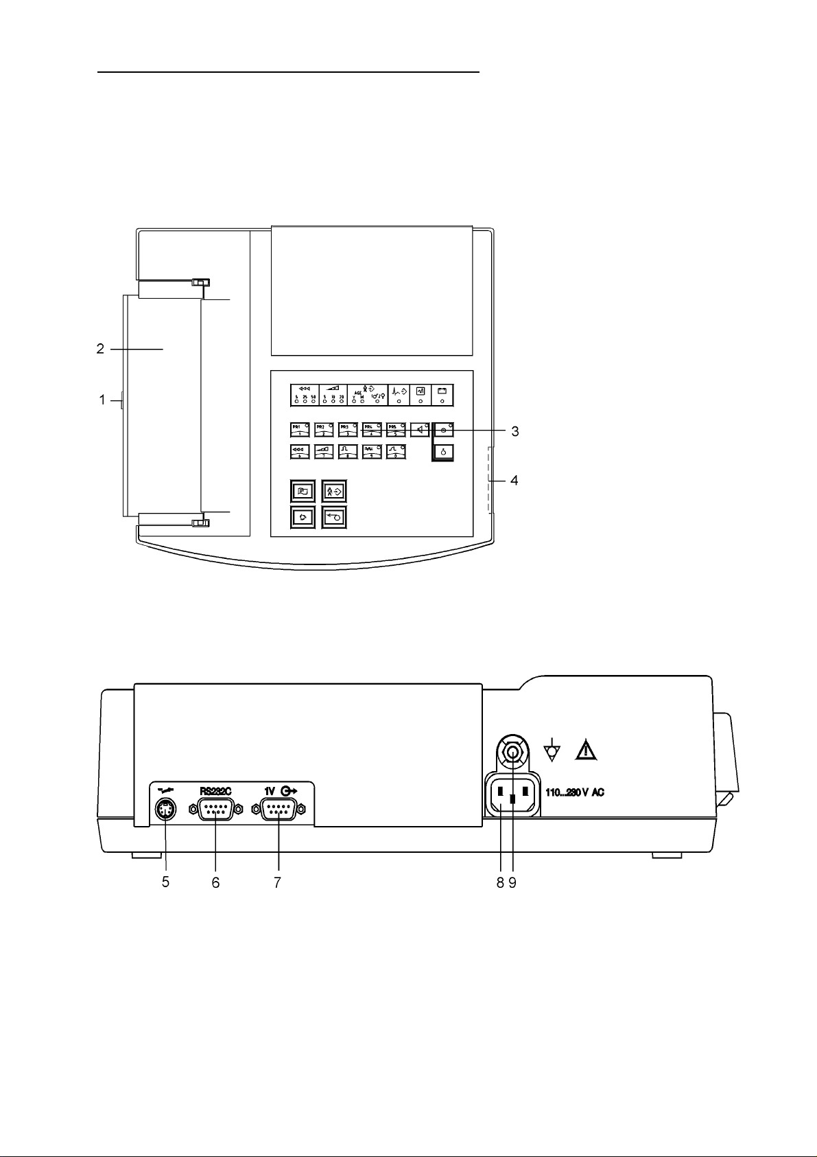
3 Operating Elements
3.1 View
Upper Side:
OPERATING ELEMENTS
1 cover opening button
2 cover of paper chamber
3 keypad
4 ECG inlet
Rear side:
5 remote start inlet
6 RS 232C interface
7 1V-outlet
8 mains cable socket
9 potential equalisation connection
3-1
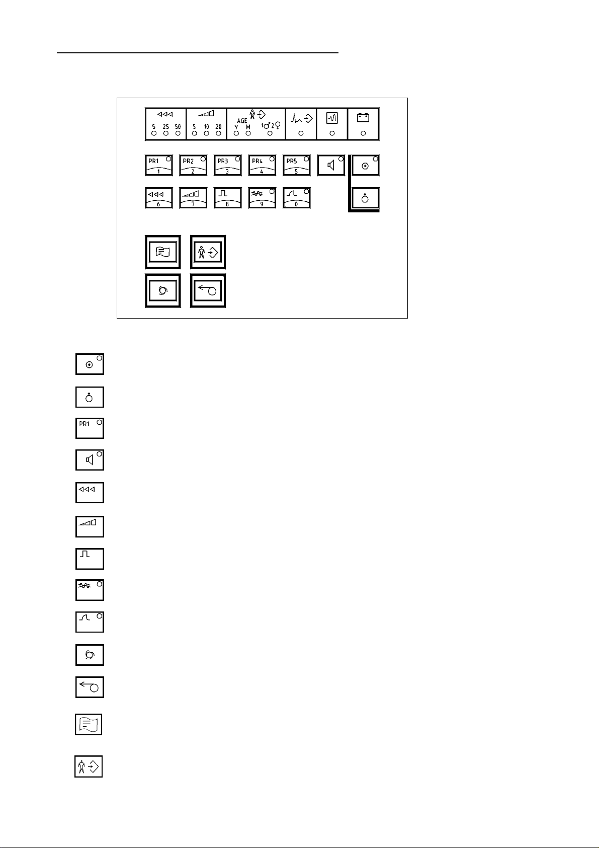
3.2 Keypad and Key Funktions
Keypad
KEYPAD AND KEY FUNKTIONS
unit on
unit off
...lead programmes
QRS-sound on/off
speed selector
sensitivity selector
1mV-test pulse
AC filter on/off
muscle filter on/off
Automatic recording programme
Manual recording proramme START / STOP
Start analysisorbereitung)
Enter patient's data(in Vorbereitung)
3-2

INSERTION OF RECORDING PAPER
4 Putting into Operation
4.1 Insertion of Recording Paper
The unit requires thermoreactive recording paper as a block of continuous stationary of 400 sheets, with
a width of 210mm and a total length of 60 m.
T o ensure good recording quality and proper paper run, it is recommended to use only original
recording paper; it can be ordered from company von Berg Medizingeräte GmbH, order No. 2700-000-021.
New recording paper should be loaded when a red marking strip appears at the lower paper margin. If all
paper is out, recording is stopped and
the indicating lamp
Recording paper must be inserted as follows:
- press the cover opening button to release the cover
- bring the cover into upright position and put it aside
- insert the paper block into the chamber, place properly, press it slightly inward and pull some paper out
(before r einser ting the cover!)
F Insert the block in such a manner, that the imprint side gets visible if the paper and is pulled to the
left . The black paper marks must be downside (towards the operator).
- reinsert cover
- bring the recording paper into a symmetric position toward the cover
- close the cover by slightly pressing its left verge
For advice on handling thermoreactive recording paper, refer to annex 2.
lights.
4.2 Application of Electrodes
4.2.1 Resting ECG
Connect the delivered patient cable to the inlet marked as ECG INLET (ref. to p. 3-1) and fix it using the
two screws.
F Defibrillation protection of unit will only be ef fective, if that patient cable specified in accessories
is used!
The accessories include 4 clamp electrodes for limb leads, and 6 chest wall suction electrodes.
Depending on the patient, prepare the application points, i.e. remove hairs and clean with alcohol. For application at the chest wall, slightly apply electrode gel to the skin areas.
For the limb electrodes, the their clamps should be prepared with electrode gel, as well.
In case of use of an ECG suction electrode system, please refer to the advice given in chapter 4.2.2.
In the following, there is an overview on the standard arrangement of electrodes.
4-1
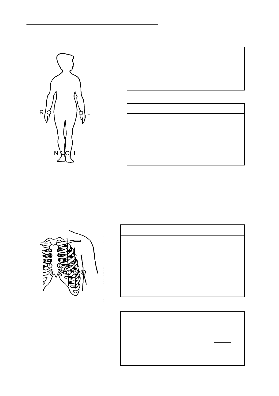
Einthoven and Goldberger Limb Leads
APPLICATION OF ELECTRODES
Electrode Code Colour Electrode Position
R red RH arm
L yellow LH arm
F green LH leg
N black RH leg
Lead Linkage of Electrodes
I L-R
II F-R
III F-L
aVR R-LF LF=(L+F)/2
aVL L-RF RF=(R+F)/2
aVF F-RL RL=(R+L)/2
Wilson Chest W all Leads
Electrode Code Colour Electrode Position
C1 white & red
C2 white & yellow 4th interspace,
C3 white & green between C2 and C4
C4 white & brown 5th interspace, LH
C5 white & black LH anterior axillary line, on
C6 white & violet LH central axillary line, on
Lead Linkage of Electrodes
V1, V 7 C1-CT
V2, V 8 C2-CT
V3, V9, V3R C3-CT CT=
V4, V4R C4-CT
V5, V5R C5-CT
V6, V6R C6-CT
4th interspace, RH sternal border
LH sternal border
midclavicular line
altitude of C4
altitude of C4
(R+L+F)
3
4-2
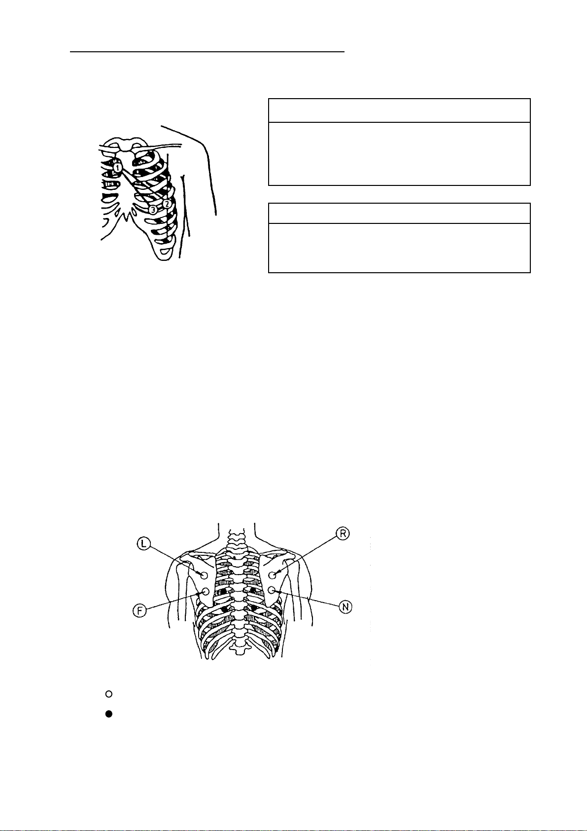
Nehb Leads
4.2.2 Exercise ECG
APPLICATION OF ELECTRODES
Electrode Code Colour Electrode Position
CN1/C1 white & red 2nd rib, RH sternal border
CN2/C2 white & yellow LH posterior axillary line on
altitude of apex beat
CN3/C3 white & green above apex beat
Lead Linkage of Electrodes
D C2-C1
A C3-C1
J C3-C2
The exercise ECG is acquired using either a suitable ECG suction-type electrode system or
adhesive electrodes and connected patient cables.
F Defibrillation protection of unit will only be effective, if that patient cable specified in accessories
is used! For use of an ECG suction-type electrode system, consider possible pieces of advice of
the instructions.
Apply the electrodes to the skin areas specially prepared in advance.
Compared with the resting ECG, a modified positioning of the extremity electrodes will be
required due to muscle exercises.
Ergometry Leads acc. to Rosenkranz and Drews:
(position further electrodes on the thorax acc. to Wilson)
classic application points in the scapula area
change paravertebral
4-3

SWITCHING THE UNIT ON AND OFF
4.3 Switching the Unit on and off
The unit can be energised using either the included, rechargeable power pack or the main supply .
4.3.1 Mains Operation
Connect the mains inlet (chapter 3-1, item 8) and the grounded mains socket of the room using the mains
cable; the charge indicator
Depending on its charge, the power pack is automatically and permanently recharged. The unit can be permanently plugged in without damages occurring to it or its power pack.
Recharging of a completely discharged power pack would take approx. 2 h.
(green LED) glows.
4.3.2 Battery Operation
The mains inlet of the unit is not connected to the mains socket - the charge indicator (green LED) does not
glow.
In case that the battery is to be used not so much, battery operation should be selected only
when an electrocardiogram must be registered very quickly , and a mains socket is not
available. A completely charged battery provides a minimum of 1 h of 6-channel recording
at 25mm/s.
Discharge of the power pack is indicated by both acoustic and optical warning. Once the charge is low
(20 %), the indication
intervals. After these signals have come, there is only a few time left for recording.
Once the power pack is discharged, a short, permanent sound comes, and the indicator blinks. After that,
the unit goes automatically off.
will change into permanent light, and a warning sound comes in certain
In order to get a maximum operation time per power pack charge, the unit has a sleep mode. That means
that after an acoustic warning the unit will always get off automatically after no key was pressed for
4 minutes. If the recording process lasts longer, the unit, of course, remains on.
4.3.3 Switching ON and OFF
Use the key to switch the unit on.
After completion of a switch-on routine, the selected programme (usually PR1) is activated, provided that
the electrodes have been properly arranged. (For information on electrode faults, refer to chapter 5.1).
Use the key to switch the unit off.
4-4
 Loading...