

Von Berg Bioset 3700 User manual

CONTENTS
Contents
Page
1 General Description................................................................................1-1
1.1 Purpose of Application........................................................................... 1-1
1.2 Unit Design ............................................................................................1-1
2 Patient’s and Unit’s Safety ..................................................................... 2-1
3 Operating Elements ................................................................................ 3-1
3.1 Top and Rear Sides.................................................................................3-1
3.2 Keyboard and Key Functions................................................................. 3-2
4 Putting into Operation............................................................................ 4-1
4.1 Insertion of Recording Paper ................................................................. 4-1
4.2 Application of Electrodes....................................................................... 4-1
4.2.1 Resting ECG .......................................................................................... 4-1
4.2.2 Exercise ECG ......................................................................................... 4-4
4.3 Switching the Unit on and off................................................................ 4-5
4.3.1 Mains Operation..................................................................................... 4-5
4.3.2 Battery Operation ................................................................................... 4-5
4.3.3 ON/OFF, Sleep Mode.............................................................................4-5
5 Patient’s Data Input ................................................................................ 5-1
5.1 Input ....................................................................................................... 5-1
5.2 Test ECG ................................................................................................5-1
6 ECG Recording ...................................................................................... 6-1
6.1 Instant ECG Recording ..........................................................................6-1
6.2 Messages ................................................................................................6-1
6.2.1 Electrode faults.......................................................................................6-1
6.2.2 Indication of the Heart Rate ................................................................... 6-2
6.3 Selection of Speed, Sensitivity, Filters ..................................................6-2
6.4 Recording in MANUAL Mode .............................................................. 6-3
6.5 Recording in AUTOMATIC Mode ........................................................ 6-4
6.6 Recording with Ergometry (Remote Start) ............................................ 6-5
7. Unit Setup .............................................................................................. 7-1
7.1 Date, Time, Code ................................................................................... 7-1
7.2 MANUAL ..............................................................................................7-2
7.3 AUTOMATICS ...................................................................................... 7-4
7.4 Language ................................................................................................ 7-6
7.5 Electrodes ............................................................................................... 7-7
7.6 Interfaces ................................................................................................7-8
7.7 Factory Setup ......................................................................................... 7-8
7.8 Print Unit Setup......................................................................................7-9
7.9 Unit Setup Structure............................................................................... 7-10
8 Interfaces ................................................................................................8-1
8.1 Analogue (1V) Outlets ........................................................................... 8-1
8.2 Serial Interface RS 232 ..........................................................................8-1
0-1

CONTENTS
Page
9 T echnical Characteristics........................................................................9-1
9.1 General Data........................................................................................... 9-1
9.2 Recording Unit .......................................................................................9-1
9.3 ECG Section........................................................................................... 9-2
9.4 Operation Section................................................................................... 9-3
9.5 Interfaces ................................................................................................9-3
10 Cleaning, Disinfection............................................................................10-1
11 Maintenance, Checks ............................................................................. 11-1
12 Environmental Protection / Waste Removal............................................12-1
Annex 1 Unit symbols used
Annex 2 Advice on handling thermoreactive recording paper
0-2

MANUFACTURER`S LIABILITY
Manufacturer’s Liability
The manufacturer can only be made liable for possible effects concerning safety , reliability , and performance
of the unit, if
- installation works, extensions, resettings, changes, or repair works are executed by persons authorised by
the manufacturer;
- the electric installation of the room meets the requirements of the applicable regulations;
- the unit is applied in accordance with this operating manual.
0-3

GENERAL DESCRIPTION
1 General Description
1.1 Purpose of Application
BIOSET 3700 is a 6-channel electrocardiograph.
The unit can be optionally equipped with accumulator, 1 V outlets and an additional computer interface.
BIOSET 3700 is intended for ECG recording under the conditions of ambulant practice and clinical routine.
Owing to its small size, low weight and possibility of battery operation, it is suited for home visits and
emergency medicine, too.
1.2 Unit Design
BIOSET 3700 is a compact unit with the upper side slightly inclined to the user.
The casing consists of two plastic shells with easy-to-clean surface.
A handle at the unit’s left hand side permits convenient carrying.
Main components:
Upper casing part including
- signal board
- keyboard
- display
- recoding unit
Lower casing part including
- power supply
1-1

PATIENT´S AND UNIT´S SAFETY
2 Patient’s and Unit’s Safety
The unit is in conformity with the Medical Products Act (MPG) and the "Guideline 93/42/EC on
medical products" and the meets thus the safety requirements as per EN 60 601-1 (IEC 601-1) as well
as the EMC requirements as per EN 60-601-1-2 (EMC act).
With reference to the above guideline, the unit is categorised as risk class IIa.
In order to protect both patient and personnel, the instrument must be earthed. This unit complies with the
protection class I. This way, it will be earthed through the protective conductor. Any usage of mainsconnecting facilities which can cause the protective conductor to be interrupted is forbidden.
For establishing the connection to the room’ s central earth connection point, use the earth clamp. If this
earth clamp is to be applied on thin-walled electric installation materials, proceed cautiously because of
destruction hazard.
If that patient cable designed for due application is used, the unit will work as a defibrillation-proof one.
Patient, unit, and bed must not be touched during defibrillation.
Conducting parts of electrodes and electrode connectors must neither touch different conducting parts
nor have earth contact.
The unit should be operated inside rooms protected against vibrations and corrosive gases. The unit w orks
at ambient temperatures of 10 °C ... 35 °C.
For a safe operation to obtain, keep the unit free from condensation water. In order to prevent that, make
the unit acclimate after relevant temperature alterations.
Once temperature and atmospheric humidity have compensated, the unit can be operated.
The unit is not intended to be run inside explosion-hazardous locations. If inflammable gas mixtures (e.g.
ether) are present, explosion hazard cannot be excluded.
If the instrument documentation does not suggest, whether or not some combination or coupling of the unit
with other devices is possible without hazards, the user has to make sure - by questioning the manufacturers/
suppliers concerned or by inquiring an expert - that the necessary safety of all included devices will not be
impaired by the combination intended.
Such a case might arise, if several devices were connected to the patient or the electrocardiograph and the
summarised lead current exceeded the admissible limits.
The devices are only allowed to be used by persons who due to their education, knowledge, and
practical experience can guarantee proper handling and who have been made familiar with the unit in
consideration of the Operating Manual.
Only those persons that due to their knowledge and practical experience are fit for briefing people on the
handling of these devices are allowed to instruct them.
2-1
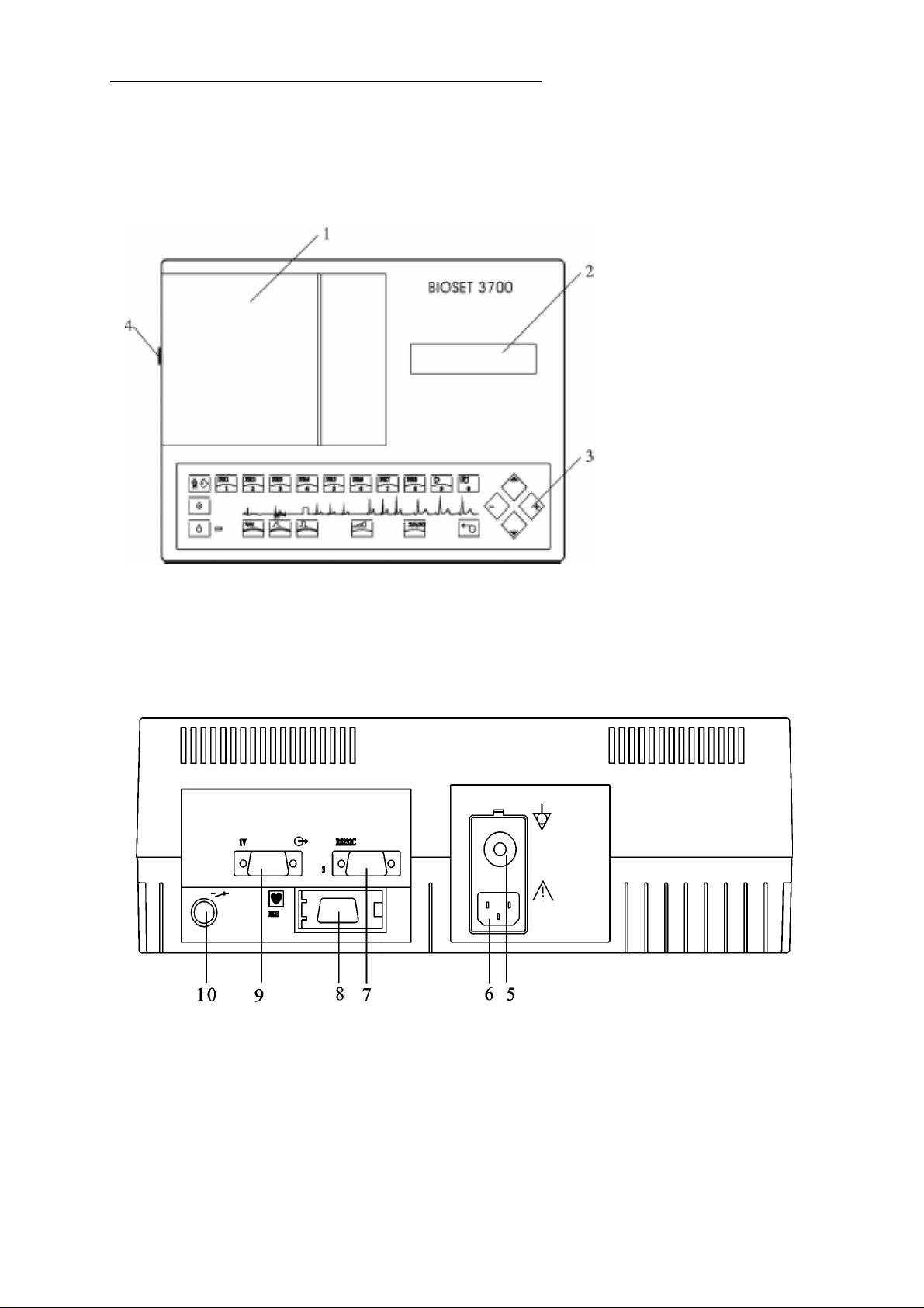
3 Operating Elements
3.1 Top and Rear Sides
Top side
TOP AND REAR SIDES
1 cover of paper chamber
2 display
3 keyboard
4 cover opening button
Rear side
5 potential equalisation connection
6 mains socket
7 RS 232C interfaces (optional)
8 patient cable connection
9 1 V outlet (optional)
10 remote start inlet
3-1
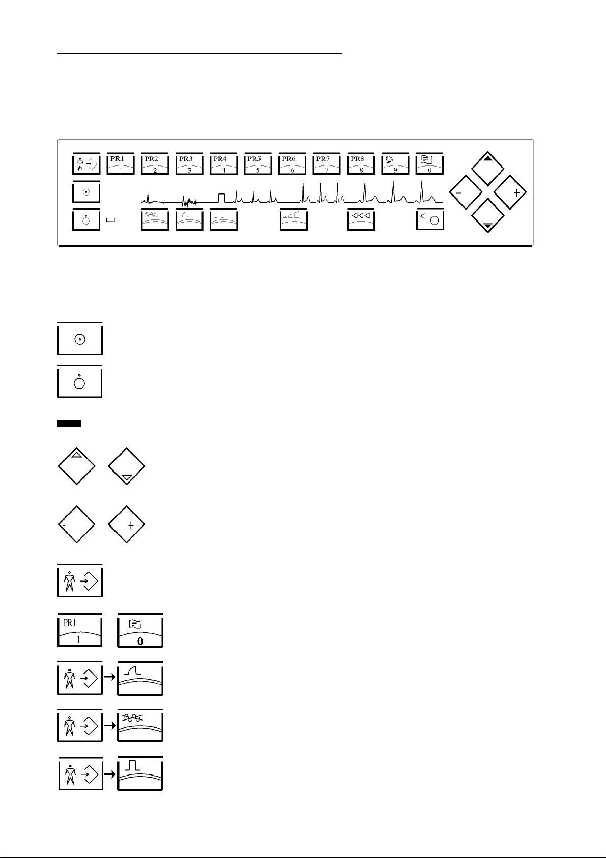
3.2 Keyboard and Key Functions
Keyboard
Basic Functions
unit ON
KEYBOARD AND KEYBOARD FUNCTIONS
unit OFF
mains indicator
cursor keys
+/- keys for parameter setting
open/close the patient’s data editor
... numeric patient’s data inputs (1...0)
unit setup
self-test
select test patient
3-2
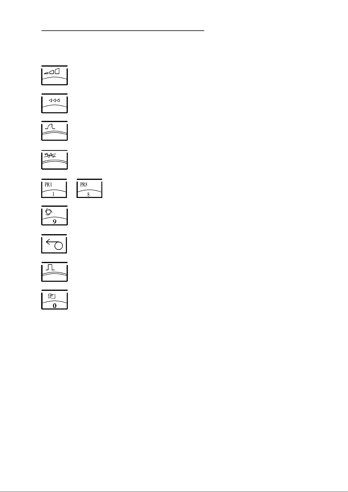
ECG recording
select sensitivity
select recording speed
muscle filter ON/OFF
AC filter ON/OFF
... select MANUAL recording programmes
KEYBOARD AND KEYBOARD FUNCTIONS
select AUTOMATIC recording programme
recording start/stop
1 mV test pulse
select ECG analysis - measurement (under preparation)
3-3
INSERTION OF RECORDING PAPER
4 Putting into Operation
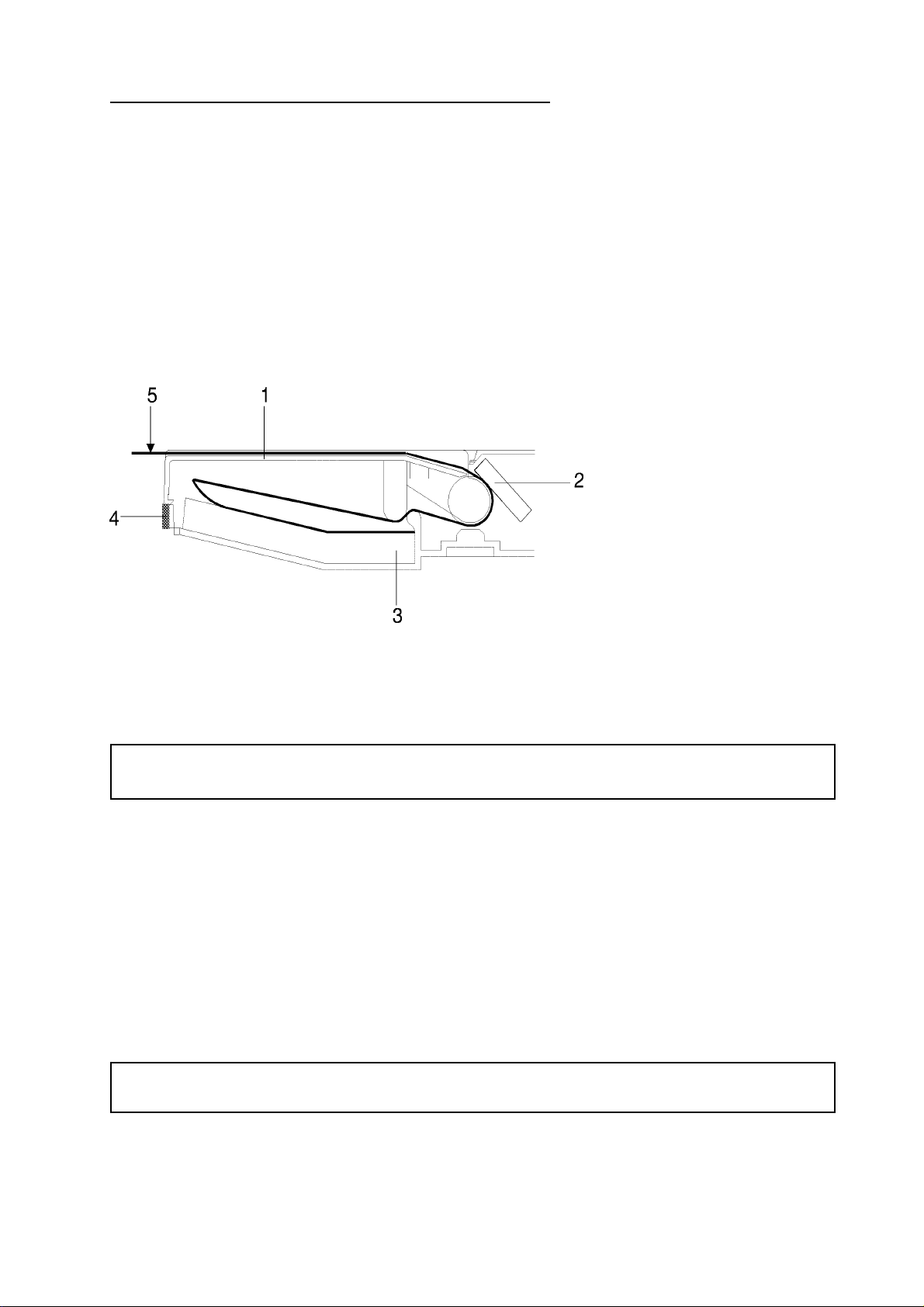
4.1 Insertion of Recording Paper
BIOSET 3700 requires thermoreactive recording paper as a block of continuous stationary of 180 sheets,
with a width of 110mm and a total length of 18m.
To ensure good recording quality and proper paper run, it is recommended to use only original recording
paper; it can be ordered from von Berg-Medizingeräte GmbH, order No. 2300-000-021.
Paper run
1 cover
2 thermal printing head
3 continuous stationary
4 cover opening button
5 imprint side
- press the cover opening button (4) to release the cover
- bring cover 1 into upright position and put it aside
- insert the paper block (3) into the chamber, place properly, and pull some paper out
Insert the block in such a manner, that the imprint side gets visible if the paper and is pulled to the left
(ref. to above illustration). The black paper marks are above (behind).
- reinsert cover 1
- bring the recording paper into a symmetric position toward the cover
- close the cover by slightly pressing its left verge
4.2 Application of electrodes
4.2.1 Resting ECG
Fix the supplied patient cable to the appropriate socket (item 8, ref. to p. 3-1).
The unit’s defibrillation protection is only effective with the patient cable supplied along
with the unit!
The electrodes should be applied to the appropriate skin areas which had been prepared before in the usual
manner.
4-1
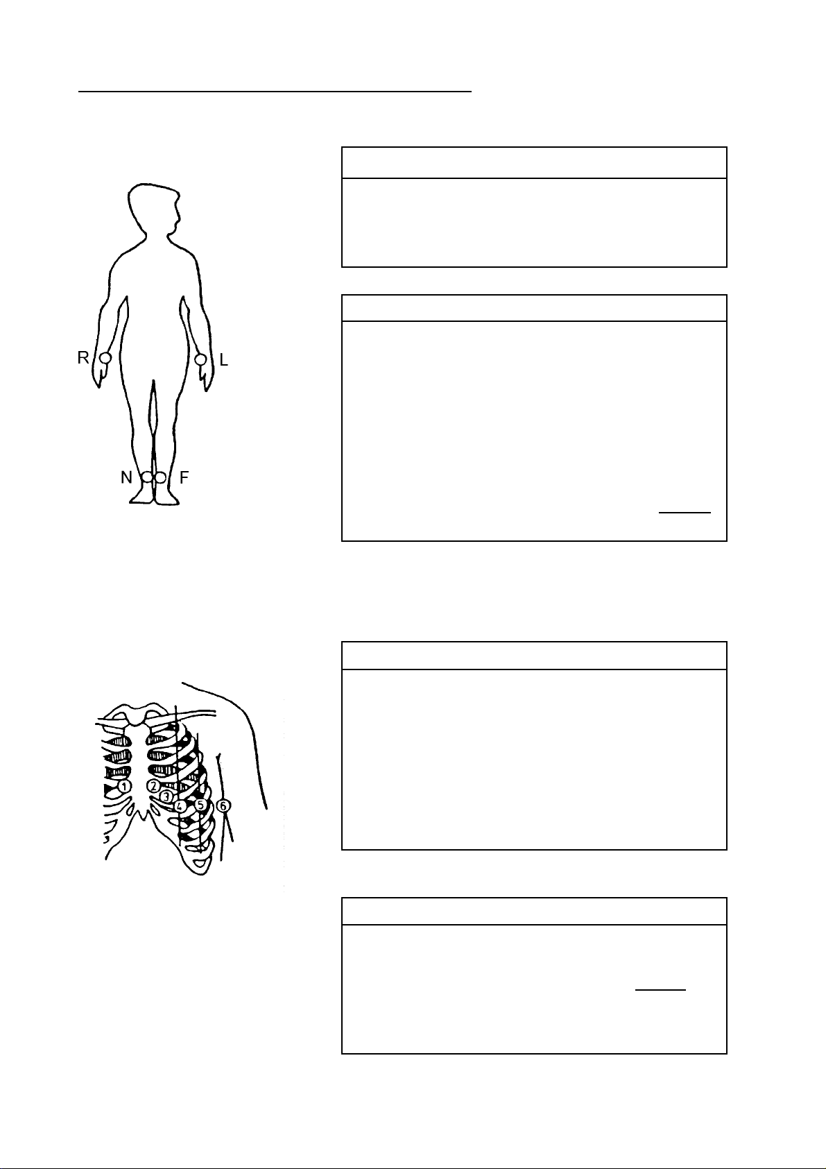
Einthoven and Goldberger Limb Leads
APPLICATION OF ELECTRODES
Electrode Code Colour Electrode Position
R red RH arm
L yellow LH arm
F green LH leg
N black RH leg
Lead Linkage of Electrodes
I L-R
II F-R
III F-L
aVR R-LF LF=(L+F)/2
aVL L-RF RF=(R+F)/2
aVF F-RL RL=(R+L)/2
Wilson Chest W all Leads
VR R-CT
VL L-CT CT=
VF F-CT
Electrode Code Colour Electrode Position
C1 white & red
C2 white & yellow 4tinterspace,
C3 white & green between C2 and C4
C4 white & brown 5th interspace, LH
C5 white & black LH anterior axillary line, on
C6 white & violet LH central axillary line, on
4thinterspace,RHsternalborder
midclavicular line
altitude of C4
altitude of C4
(R+L+F)
3
LHsternalborder
Lead Linkage of Electrodes
V1, V7 C1-CT
V2, V8 C2-CT
V3, V9, V3R C3-CT CT=
V4, V4R C4-CT
V5, V5R C5-CT
V6, V6R C6-CT
(R+L+F)
3
4-2
APPLICATION OF ELECTRODES
Expanded Chest Wall Leads
For the expanded leads, the electrodes can be allocated freely to the leads In the basic setup (ref. to chapter
9.2). The typical allocation is preselected in the factory setup.
Lead Electrode Electrode Position
V7 C1 4th interspace, LH posterior axillary line
V8 C2 4th interspace, LH scapular line
V9 C3 4th interspace, LH paravertebral line
V3R C3 between V1 and V4R
V4R C4 4th interspace, RH midclavicular line
V5R C5 between V4R and V6R
V6R C6 height V4R LH midaxillary line
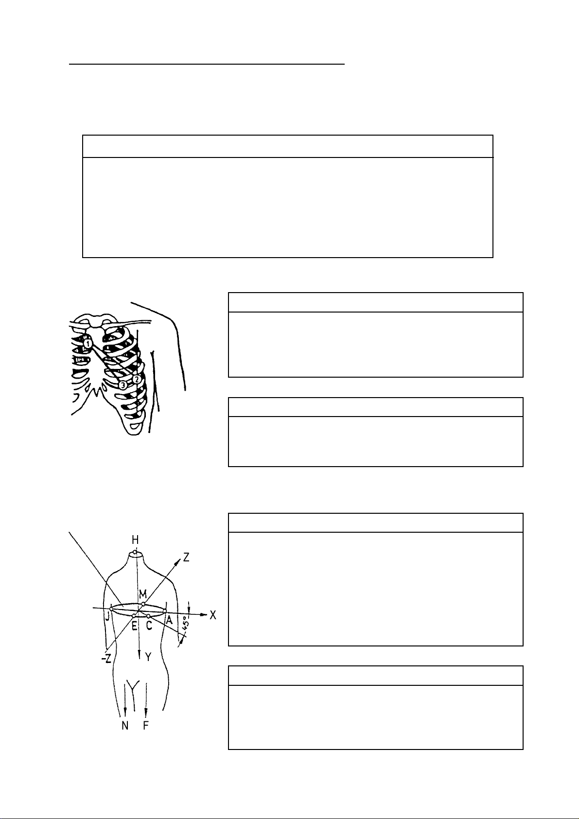
Nehb Leads
Electrode Code Colour Electrode Position
/ CN1,C1 white & red 2nd rib, RH sternal border
CN2/C2 white & yellow LH posterior axillary line on altitude
of apex beat
CN3/C3 white & green above apex beat
Frank Leads
Lead Linkage of Electrodes
D C2-C1
A C3-C1
J C3-C2
Electrode Code Colour Electrode Position
J/C1 white & red altitude of 4th interspace
E/C2 white & yellow altitude of 4th interspace
C/C3 white & green altitude of 4th interspace
A/C4 white & brown altitude of 4th interspace
M/C5 white & black altitude of 4th interspace
H/C6 white & violet neck
F green LH leg
N black RH leg
Lead Linkage of Electrodes
Vx 0,610xC4+0,171xC3-0,781xC1
Vy 0,655xF +0,345xC5-1,000xC6
Vz 0,133xC4+0,736xC5-0,264xC1
-0,373x C2-0,231x C3
4-3
EXERCISE ECG
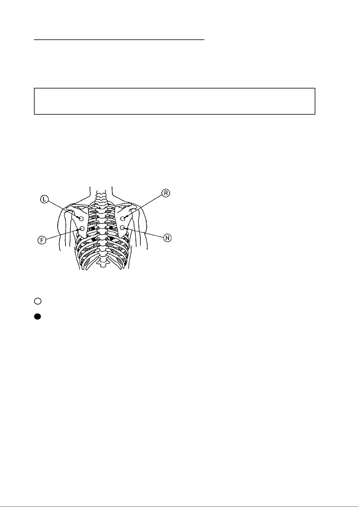
4.2.2
Exercise ECG
The exercise ECG is acquired using either a suitable ECG suction-type electrode system or adhesive electrodes
and connected patient cables.
Defibrillation protection of unit will only be effective, if that patient cable specified in accessories
is used! For use of an ECG suction-type electrode system, consider possible pieces of advice of
the instructions.
Apply the electrodes to the skin areas specially prepared in advance.
Compared with the resting ECG, a modified positioning of the extremity electrodes will be required due to
muscle exercises.
Ergometry Leads acc. to Rosenkranz and Drews:
(position further electrodes on the thorax acc. to Wilson)
classic application points in the scapula area
· change paravertebral
4-4
 Loading...