

Volvo Trucks MID 146 Service Manual

Service Manual
Trucks
Group 87
Fault Codes, Climate Control
MID 146
CU-BAS, CU-MCC, CU-ECC
VN, VHD VERSION2
PV776-TSP196483


Foreword
The descriptions and service procedures contained in this manual are based on designs
and methods studies carried out up to October 2003.
The products are under continuous development. Vehicles and components produced
after the above date may therefore have different specifications and repair methods.
When this is believed to have a significant bearing on this manual, supplementary
service bulletins will be issued to cover the changes.
The new edition of this manual will update the changes.
In service procedures where the title incorporates an operation number, this is a
reference to an V.S.T. (Volvo Standard Times).
Service procedures which do not include an operation number in the title are for general
information and no reference is made to an V.S.T.
Each section of this manual contains specific safety information and warnings which
must be reviewed before performing any procedure. If a printed copy of a procedure is
made, be sure to also make a printed copy of the safety information and warnings that
relate to that procedure. The following levels of observations, cautions and warnings
are used in this Service Documentation:
Note: Indicates a situation, handling or circumstance which should be observed.
Caution: Indicates a potentially hazardous situation which, if not avoided, may result in
minor or moderate injury or damage to property.
Warning: Indicates a potentially hazardous situation which, if not avoided, could result
in death, serious injury or major damage to property.
Danger: Indicates an imminently hazardous situation which, if not avoided, will result in
death or serious injury.
Volvo Trucks North America, Inc.
Greensboro, NC USA
Order number: PV776-TSP196483
Repl: This Service Manual replaces Service Manual 87, “Fault Codes, Climate Control MID 146” (11.2002), publication
number PV776–TSP177273 and Service Bulletin 870–14, “Fault Codes, Climate Control MID 146, New Tool, 84105675”
(08.2003), publication number PV776–TSP194734
© 2003 Volvo Trucks North America, Inc., Greensboro, NC USA
All rights reserved. No part of this publication may be reproduced, stored in
retrieval system, or transmitted in any forms by any means, electronic,
mechanical, photocopying, recording or otherwise, without the prior written
permission of Volvo Trucks North America, Inc..
USA14332

Contents
Specifications.........................................................................................3
ClimateUnit,SignalDescription............................................................3
Tools........................................................................................................7
SpecialEquipment.................................................................................7
Troubleshooting.....................................................................................9
MID146FaultCodeTable.....................................................................9
MID146SID2TemperatureSensor,Evaporator................................11
MID146SID2TemperatureSensorEvaporator,Check.....................12
MID146SID5StepperMotor,FreshAirandRecirculation................14
MID146SID5StepperMotorFreshAir-recirculation,Check.............15
MID146SID6StepperMotor,AirDistribution....................................16
MID146SID6StepperMotorAirDistribution,Check.........................17
MID146SID9StepperMotor,AirMix.................................................18
MID146SID9StepperMotor,AirMix/HeatControl,Check..............19
MID146SID11SolenoidClutch,Compressor...................................20
MID146SID12WaterControlValve..................................................21
MID146SID12WaterControlValve,Check......................................22
MID146SID13TemperatureSensor,HeatExchanger......................24
MID146SID13TemperatureSensorHeatExchanger,Check...........25
MID146SID14CirculationFan,TemperatureSensor,Cab...............27
MID146SID15EngineFanRequest..................................................28
MID146SID16StepperMotor,Phase1............................................29
MID146SID16StepperMotorPhase1,Check.................................30
MID146SID17StepperMotor,Phase2............................................31
MID146SID17StepperMotorPhase2,Check.................................32
MID146SID18StepperMotor,Phase3............................................33
MID146SID18StepperMotorPhase3,Check.................................34
MID146SID19StepperMotor,Phase4............................................35
MID146SID19StepperMotorPhase4,Check.................................36
MID146SID22PressureSensor,Refrigerant....................................37
MID146SID22PressureSensorRefrigerantHighPressureSide,
Check..................................................................................................38
MID146SID2325VoltSupplySensors.............................................40
MID146SID2325VoltSupplySensors,Check.................................41
MID146SID250J1708InformationLink............................................42
MID146PID170TemperatureSensor,Cab.......................................43
MID146PID170TemperatureSensorCab,Check............................44
MID146PID171TemperatureSensor,AmbientTemperature...........46
OperationNumbers
1

2
Group 87 Climate Control, Fault Codes Specifications
Specifications
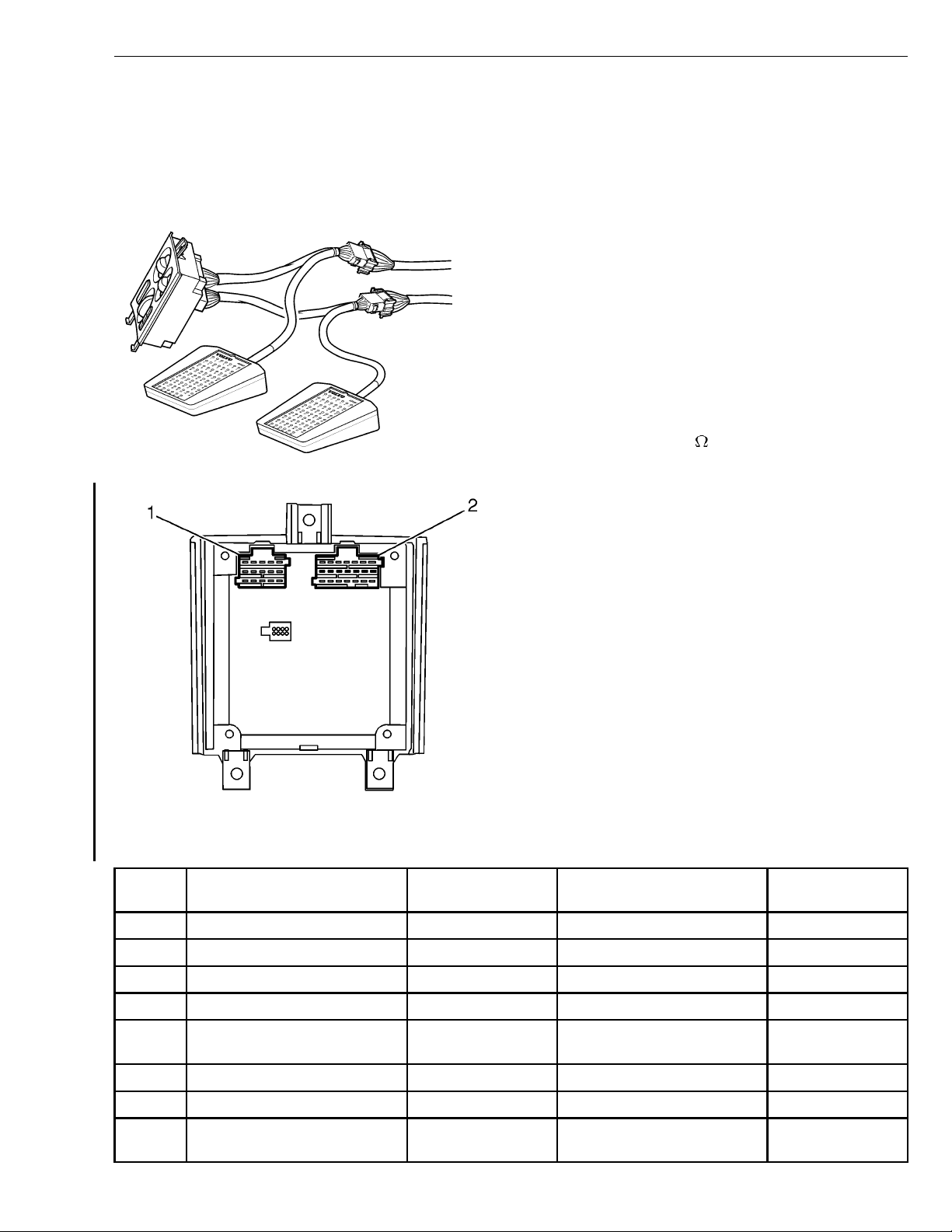
Climate Unit, Signal Description
Connection between the control unit and cable harness
Conditions:
Breakout box 9998699 connected to adapter 9998596
•
between the control unit and cable harness.
Breakout box 9998699 connected to adapter 9990025
•
between the control unit and cable harness.
V = direct current voltage (V)
B+ = battery voltage
1 BSA (15 pin)
2 BSB (21 pin)
Terminal
Signal type
T8008833
W8003419
Measurement
points
R = resistance in ohms (
Nominal value
)
Other
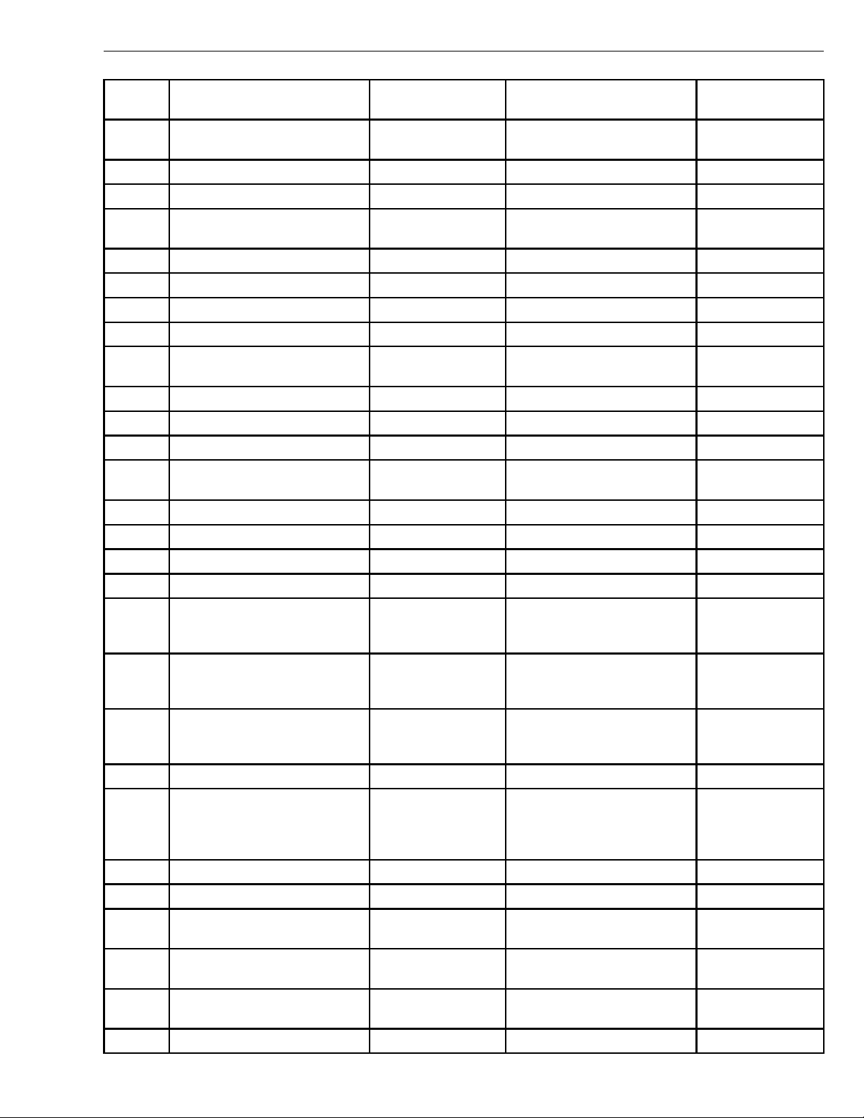
BSA1 Not connected
BSA2 Not connected
BSA3 Not connected
BSA4 Not connected
BSA5 Sensor cab temperature, signal
voltage
BSA6 Dash Illumination BSA6 - BSA15 V ≈ 5 - 12 V 10 - 90 % of B+
BSA7
BSA8 Fan control, signal voltage BSA8 - BSA15 V ≈ 0 - 10 V Rotate fan control
BSA5 - BSB3 V ≈ 0–5V
knob
3
Group 87 Climate Control, Fault Codes Specifications
Terminal
BSA9 Power supply, ignition key in
BSA10
BSA11 Supply voltage BSA11 - BSA15 V ≈ B+
BSA12 Magnetic clutch, air
BSA13
BSA14 Fan, sensor cab temperature BSA14 - BSA15 V ≈ B+
BSA15 Ground connection BSA15 - Ground V ≈ 0VDC
BSB1
BSB2 Engine fan control BSB2 - BSA15 V ≈ B+ Engine cooling fan
BSB3 Ground terminal sensor BSB3 - Ground V ≈ 0VDC
BSB4 SAE J1708 Data link B BSB4 - Ground V ≈ 0-5VDC
BSB5 SAE J1708 Data link A BSB5 - Ground V ≈ 0 - 5V DC
BSB6 Sensor sytem pressure, signal
Signal type
driving position
conditioning (A/C) compressor
volts
Measurement
points
BSA9 - BSA15 V ≈ B+
BSA12 - BSA15 V ≈ B+ Engine running
BSB6 - Ground V ≈ 0.5 - 4.5 V DC
Nominal value
Other
15
30
31
active
BSB7 Stepper motor phase 1 (low)
BSB8 Stepper motor phase 2 (low)
BSB9 Stepper motor phase 3 (low)
BSB10 Stepper motor phase 4 (low)
BSB11 Stepper motor, by pass, signal
voltage
BSB12 Stepper Motor, Air distribution,
signal voltage
BSB13 Stepper Motor, recirculation,
signal voltage
BSB14
BSB15 Engine coolant valve, voltage
supply
BSB16
BSB17
BSB18 Sensor system pressure,
voltage supply (5v)
BSB11 - BSB7 - 10 V ≈ <10V Stepper motor
active (Rotate
knob)
BSB12 - BSB7 - 10 V ≈ <10V Stepper motor
active (Rotate
knob)
BSB13 - BSB7 - 10 V ≈ <10V Stepper motor
active (Rotate
knob)
BSB15 - BSA15 V ≈ B+ Select Max heat
position, Electronic
climate control
(ECC) only
BSB18 - BSA15 V ≈ 4.5 - 5.5V
BSB19 Temperaturesensorevaporator,
signal voltage
BSB20 Temperature sensor, heat
exchanger, signal voltage
BSB21 Not connected
4
BSB19 - BSA15 V ≈ 0-5V
BSB20 - BSA15 V ≈ 0-5V
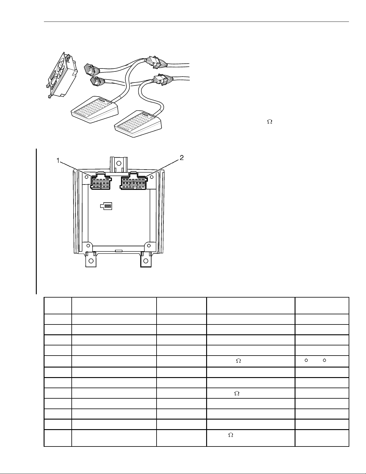
Group 87 Climate Control, Fault Codes Specifications
Connected to the cable harness
Conditions:
Breakout box 9998699 with adapter 9990025
•
connected to cable harness.
Breakout box 9998699 with adapter 9998596
•
connected to cable harness.
Control unit disconnected.
•
1 BSA (15 pin)
2 BSB (21 pin)
T8008832
W8003419
R = resistance in ohms (
)
Terminal
BSA1
BSA2
BSA3
BSA4
BSA5 Sensor cab temperature BSA5 - BSB3 R ≈ 12.5 k
BSA6
BSA7
BSA8 Fan control BSA8 - BSA15 R ≈ 100 k
BSA9
BSA10
BSA11
BSA12 Magnetic clutch, air
Signal type
conditioning (A/C) compressor
Measurement
points
BSA12 - BSA15 R ≈ 6k
Nominal value
Other
20 C (68 F)
5
Group 87 Climate Control, Fault Codes Specifications
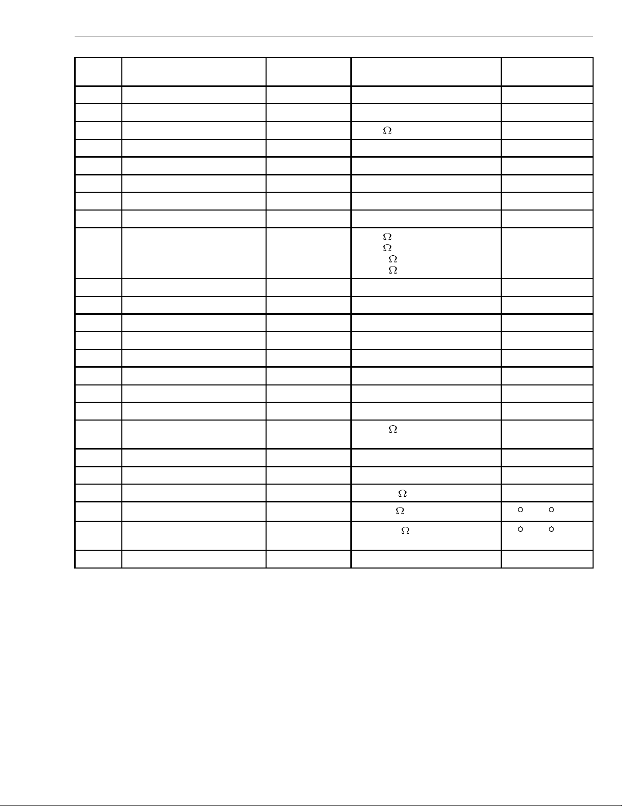
Terminal
BSA13
BSA14
BSA15 Ground connection BSA15 - Ground R ≈ 0
BSB1
BSB2
BSB3
BSB4
BSB5
BSB6 Sensor, system pressure BSB6 - BSB3 R ≈ 2
BSB7
BSB8
BSB9
BSB10
BSB11
Signal type
Measurement
points
Nominal value
R ≈ 6
R ≈ 10
R ≈ 15
Other
2 bar
9 bar
18 bar
30 bar
BSB12
BSB13
BSB14
BSB15 Engine coolant valve, voltage
supply
BSB16
BSB17
BSB18 Sensor, system pressure BSB18 - BSB3 R ≈ 112 k 4.5 bar
BSB19 Temperature sensor evaporator BSB19 - BSB3 R ≈ 3.5 k
BSB20 Temperature sensor heat
exchanger
BSB21 Not connected
BSB15 - BSA11 R ≈ 50 FuseF32,removed
20 C (68 F)
BSB20 - BSB3 R ≈ 12.5 k
20 C (68 F)
6
Group 87 Climate Control, Fault Codes Tools
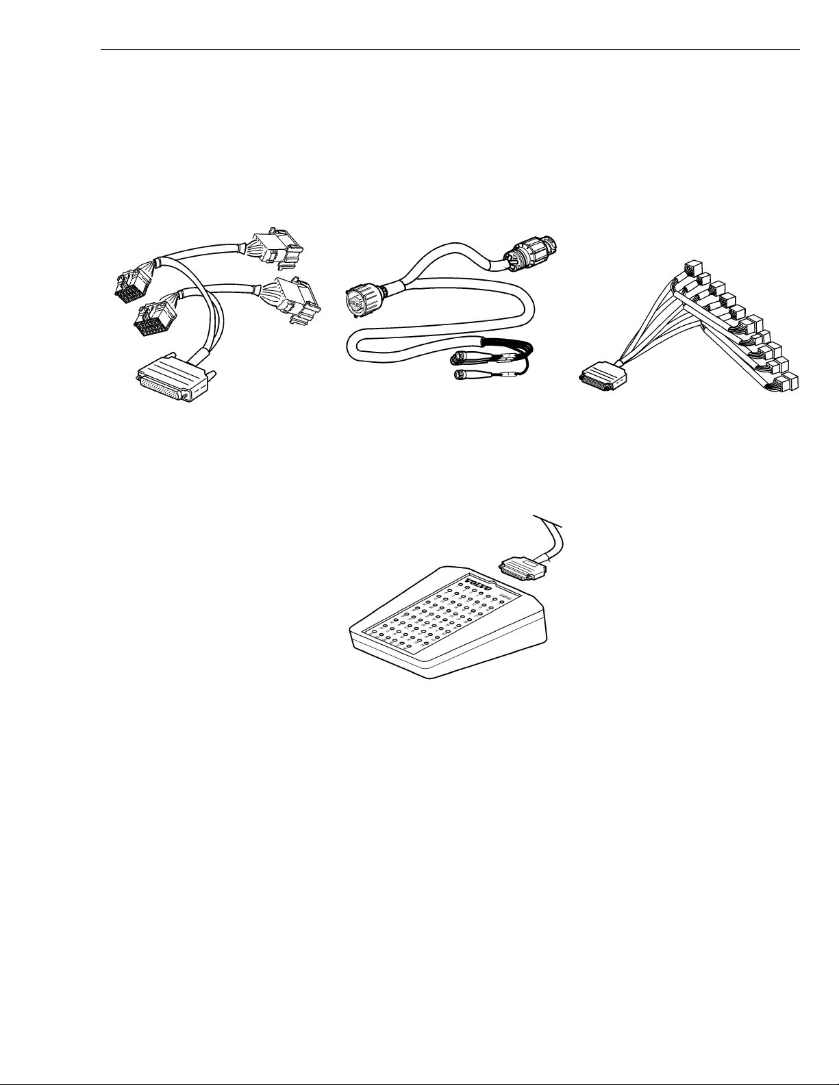
Tools
Special Equipment
For special tools and other special equipment ordering instructions, see tool information
in group 08.
Special tools
9990025 9998534 9998596
AC Adapter 4 pin DIN adapter AC Adapter
9998699
Breakout box
7
Group 87 Climate Control, Fault Codes Tools
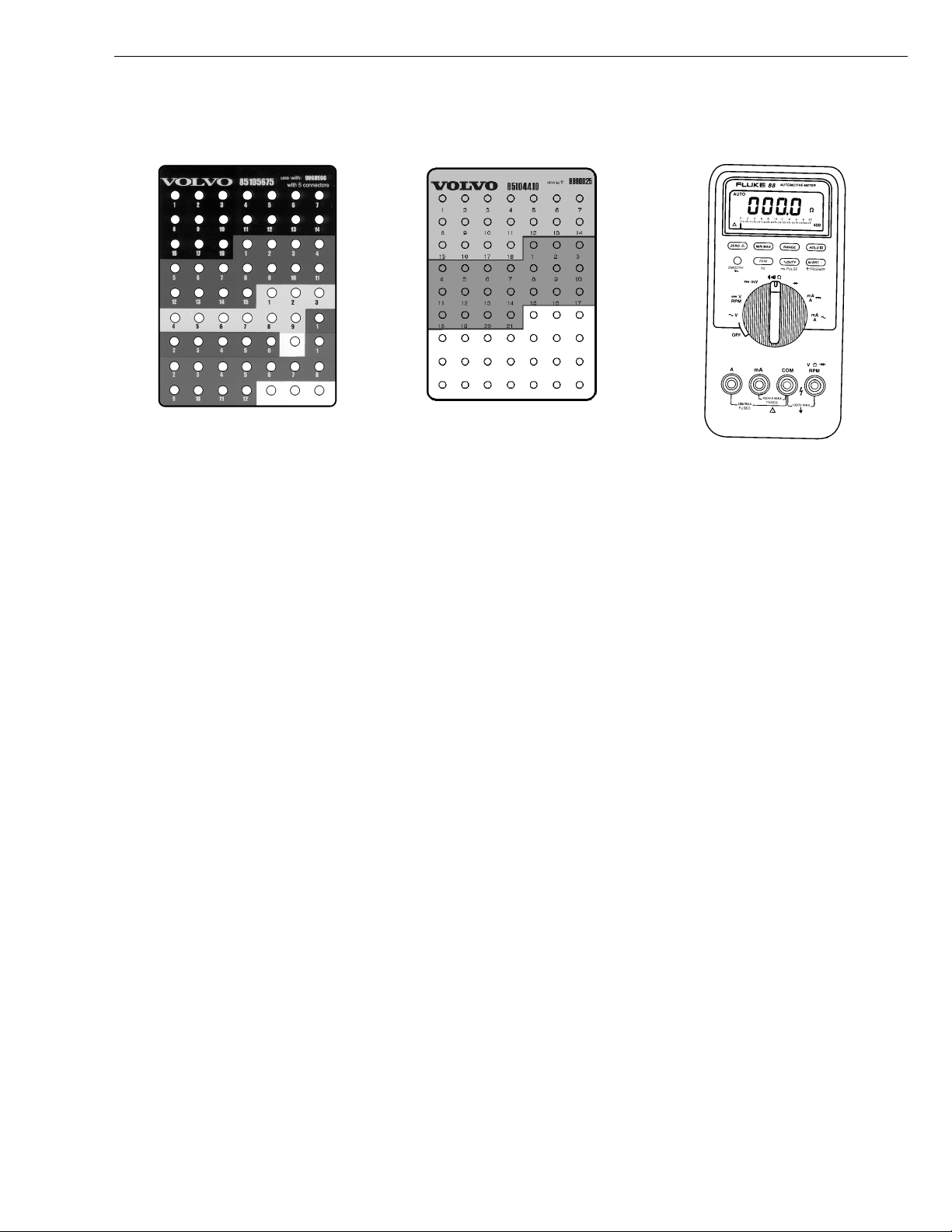
Other special equipment
85105675 85104410 J-39200
Overlay used with 9998596 Overlay used with 9990025 Digital Multimeter
8

Group 87 Climate Control, Fault Codes Troubleshooting
Troubleshooting
MID 146 Fault Code Table
MID:
Message Identification Description (identification of
control unit).
SID:
Subsystem Identification Description (identification of
component).
PID:
Parameter Identification Description (identification of
parameter (Value)).
PPID:
Proprietary Parameter Identification Description (Volvo
unique identification of parameter (value)).
Fault code
MID 146 SID 2 Temperature sensor, evaporator
MID 146 SID 5 Stepper Motor, Fresh Air and Recirculation
MID 146 SID 6 Stepper motor, air distribution
MID 146 SID 9 Stepper motor, air mixture (ECC), heat
MID 146 SID 11 Magnetic clutch, air conditioning (A/C)
MID 146 SID 12 Solenoid valve, water control
MID 146 SID 13 Temperature sensor, heat exchanger
MID 146 SID 14 Circulation fan, temperature sensor, cab
MID 146 SID 15 Fan connection, engine
MID 146 SID 16 Stepper motor, phase 1
MID 146 SID 17 Stepper motor, phase 2
MID 146 SID 18 Stepper motor, phase 3
MID 146 SID 19 Stepper motor, phase 4
MID 146 SID 22 Pressure sensor, refrigerant, high pressure
MID 146 SID 232 5 volts supply to the sensor
Component / function
control (MCC, BAS)
compressor
side
PSID:
Proprietary Subsystem Identification Description
(Volvo-unique identification of component).
FMI:
Failure Mode Identifier (identification of fault type).
For more detailed information concerning these
designations, see service information group 0 ”Vehicle
Electronics ’98”.
FMI
3. 4
4
4
4
4
3
3. 4
4
3
3
3
3
3
3. 4
4
Section
“MID 146 SID 2 Temperature
Sensor, Evaporator” page 11
“MID 146 SID 5 Stepper Motor,
FreshAir and Recirculation” page
14
“MID 146 SID 6 Stepper Motor,
Air Distribution” page 16
“MID 146 SID 9 Stepper Motor,
Air Mix” page 18
“MID 146 SID 11 Solenoid Clutch,
Compressor” page 20
“MID 146 SID 12 Water Control
Valve” page 21
“MID 146 SID 13 Temperature
Sensor, Heat Exchanger” page
24
“MID 146 SID 14 Circulation Fan,
Temperature Sensor, Cab” page
27
“MID 146 SID 15 Engine Fan
Request” page 28
“MID 146 SID 16 Stepper Motor,
Phase 1” page 29
“MID 146 SID 17 Stepper Motor,
Phase 2” page 31
“MID 146 SID 18 Stepper Motor,
Phase 3” page 33
“MID 146 SID 19 Stepper Motor,
Phase 4” page 35
“MID 146 SID 22 Pressure
Sensor, Refrigerant” page 37
“MID 146 SID 232 5 Volt Supply
Sensors” page 40
9
Group 87 Climate Control, Fault Codes Troubleshooting
Fault code
MID 146 SID 250 SAE J1708 data link
MID 146 PID 170 Cab, temperature sensor
MID 146 PID 171 Temperature sensor, outer temperature
Component / function
FMI table
SAE standard
FMI Display text
0
1
2
3
4
5
6
7
Value too high Data applicable, but above normal operating range.
Value too low Data applicable, but below normal operating range.
Incorrect data Intermittent or incorrect data.
Electrical fault Abnormally high voltage or short-circuit to higher voltage.
Electrical fault Abnormally low voltage or short-circuit to lower voltage.
Electrical fault Abnormally low current or open-circuit.
Electrical fault Abnormally high current or short-circuit to ground.
Mechanical fault Incorrect response from the mechanical system.
SAE text
FMI
9
3. 4
3. 4
Section
“MID 146 SID 250 J1708
Information Link” page 42
“MID 146 PID 170 Temperature
Sensor, Cab” page 43
“MID 146 PID 171 Temperature
Sensor, Ambient Temperature”
page 46
8
9
10
11
12
13
14
15
Mechanical or
electrical fault
Communication fault Abnormal update rate.
Mechanical or
electrical fault
Unknown fault Unidentifiable fault.
Component fault Defective unit or component.
Incorrect calibration Calibration values outside the limits.
Unknown fault Special instructions.
Unknown fault Reserved for future use.
Abnormal frequency.
Abnormally high variations.
10
Group 87 Climate Control, Fault Codes Troubleshooting
MID 146 SID 2 Temperature Sensor, Evaporator
Fault code
FMI 3
Abnormally high voltage or short-circuit to higher voltage.
Conditions for fault code:
If the control unit detects a voltage higher than
•
4.86 volts the control unit interprets this as an error
T8008634
and a fault code is stored.
Possible cause:
Connector to sensor disconnected
•
Signal cable short-circuited to higher voltage
•
Ground lead short-circuited to higher voltage
•
Reaction from the control unit:
Fault code is stored
•
T8008560
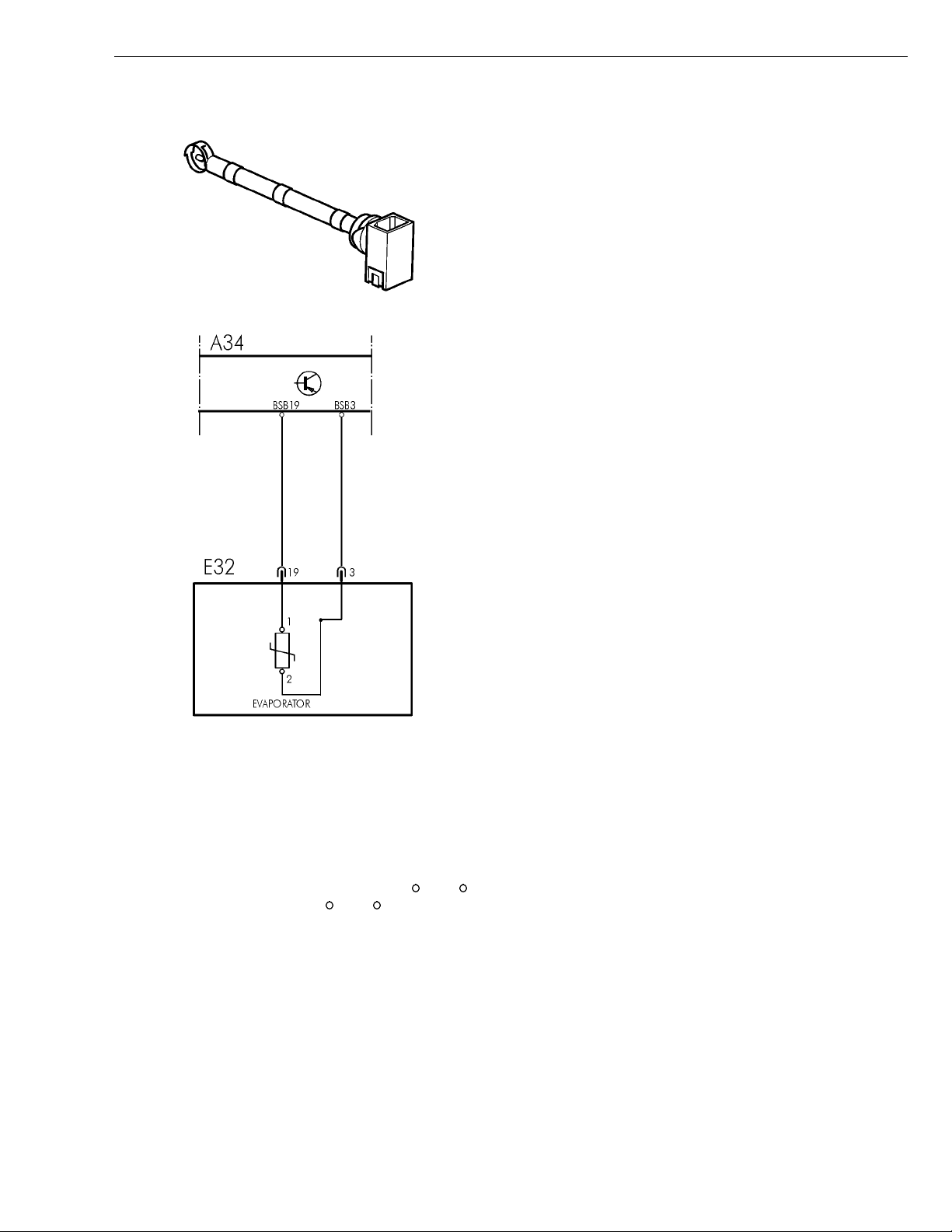
Component:A34 Climate Control Unit, E32 Climate
Unit
General information
The sensor measures the air temperature after the
evaporator and before the blower fan. The temperature
signal is used to protect the evaporator against icing
by engaging and disengaging the compressor. The
compressor is disengaged at approximately 3
and engages at approximately 8
C (46 F).
C (37 F)
Yellow lamp requested
•
Noticeable external symptoms:
Yellow lamp lights up
•
The compressor "cycles" 20 s active, 60 s inactive
•
Appropriate check:
See “MID 146 SID 2 Temperature Sensor Evaporator,
•
Check” page 12
FMI 4
Abnormally low voltage or short-circuit to lower voltage
Conditions for fault code:
If the control unit detects a voltage lower than 0.24 volts
•
the control unit interprets this as an error and a fault
code is stored.
Possible cause:
Signal cable short-circuited to ground
•
Reaction from the control unit:
Fault code is stored
•
Yellow lamp requested
•
Noticeable external symptoms:
Yellow lamp lights up
•
The compressor "cycles" 20 s active, 60 s inactive
•
Appropriate check:
See “MID 146 SID 2 Temperature Sensor Evaporator,
•
Check” page 12
11

Group 87 Climate Control, Fault Codes Troubleshooting
8730-21-02-01
MID 146 SID 2 Temperature Sensor Evaporator, Check
Special tools: 9990025, 9998699
Other special equipment: J-39200
NOTE
Check all relevant connectors. Check for loose
•
connections, contact resistance and oxidation. For a
more detailed description of fault-tracing wiring
and connectors, see separate service information
under Group 371.
Measurement at the component
connector to the control unit
Note: If one of the values below is incorrect this may also
have caused the component to fail, check the component
if any of the values are incorrect.
Ground lead
1
Conditions:
Measuring voltage using the J-39200 Digital
•
Multimeter.
Ignition key in the drive position.
•
Measurement to the control unit.
•
Control unit connected.
•
Measurement points Nominal value
BSB3 - Ground V ≈ 0V
J-39200
9998699
, 9990025
12
Group 87 Climate Control, Fault Codes Troubleshooting
Signal cable
2
Conditions:
Measuring voltage using the J-39200 Digital
•
Multimeter.
Engine with increased idle speed approx. 1000 rpm.
•
Measurement to the control unit.
•
Control unit connected.
•
Air conditioning (A/C) system active.
•
Measurement points Nominal value
BSB3 - BSB19
J-39200
9998699
, 9990025
V ≈ 3.64 - 3.85 V (-10 C,
14
F)
V ≈ 1.94 - 2.10 V (20
68
F)
V ≈ 1.06 - 1.18 V (40
104
F)
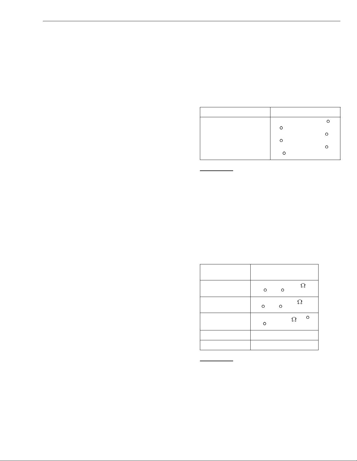
Checking component
3
Conditions:
The component connector disconnected.
•
Measuring resistance using a J-39200 Digital
•
Multimeter.
Measurement to the component.
•
Measurement
points
1-2
1-2
1-2
Nominal value
R ≈ 14.92 - 15.51 k
(-10 C, 14 F)
R ≈ 3.37 - 3.53 k
(20 C, 68 F)
R ≈1.43 -1.51 k (40 C,
104
F)
C,
C,
1 - ground Open circuit
2 - ground Open circuit
J-39200
13
 Loading...