

Volvo Penta TAD530, TAD420VE, TD520VE, TAD520VE, TAD531 Workshop Manual
...
I
1(0)
Workshop Manual
Technical Data
TD420VE, TAD420VE, TD520GE, TAD520GE, TD520VE
TAD520VE, TAD530/531/532GE, TAD620VE, TAD650VE
TAD660VE, TD720GE TAD720GE, TD720VE, TAD720VE
TAD721GE, TAD721VE, TAD722GE, TAD722VE,
TAD730/731/732/733GE, TAD750VE, TAD760VE


1
General InformationGroup 20
Safety precautions ...............................................2
General information ............................................. 5
Repair instructions ............................................... 6
Location of identification plates
TD/TAD420-620, TD/TAD520-722 .......................9
TAD650/660, TAD750/760 .................................. 10
TD420VE, TAD420VE, TAD620VE, TAD650VE,
TAD660VE
General (420/620)................................................ 11
General (650/660)................................................ 12
Engine block ....................................................... 12
Valve mechanism ...............................................16
Crank mechanism ............................................... 19
Lubricating system .............................................. 22
Fuel system ........................................................ 24
Intake and exhaust system ................................. 32
Cooling system ................................................... 32
Tightening torque ................................................33
TD520GE, TAD520GE, TD520VE, TAD520VE,
TAD530-532GE
General ............................................................... 36
Engine block ....................................................... 37
TD420VE, TAD420VE, TAD620VE, TAD650VE, TAD660VE,
TD520GE, TAD520GE, TD520VE, TAD520VE,
TAD530/531/532GE, TD720GE, TAD720GE, TD720VE,
TAD720VE, TAD721GE, TAD721VE, TAD722GE, TAD722VE,
TAD730/731/732/733GE, TAD750VE, TAD760VE
Valve mechanism ............................................... 40
Crank mechanism ............................................... 43
Lubricating system .............................................. 46
Fuel system ........................................................ 48
Intake and exhaust system ................................. 55
Cooling system ................................................... 56
Tightening torque ................................................57
TD720GE, TAD720GE, TD720VE, TAD720VE,
TAD721GE, TAD721VE, TAD722GE, TAD722VE,
TAD730-733GE, TAD750VE, TAD760VE
General (720-722GE ) ......................................... 59
General (720-722VE) ...........................................60
General (750/760)................................................ 60
Engine block ....................................................... 61
Valve mechanism ............................................... 64
Crank mechanism ............................................... 67
Lubricating system .............................................. 70
Fuel system ........................................................ 72
Intake and exhaust system ................................. 80
Cooling system ................................................... 81
Tightening torque ................................................82
Tightening diagram ............................................. 85
Contents
Technical Data
Industrial Engines
© 2007 AB VOLVO PENTA
All rights to changes or modifications reserved.
Printed on environmentally-friendly paper
2
General Information Group 20
Introduction
Workshop Manuals contains technical specifications,
descriptions, and instructions for the repair of the specified Volvo Penta products or product types. Check
that you have the correct Workshop Manual and the
latest Service Bulletins for your engine.
Before starting work on the engine, read these
sections of the Workshop Manual:
Safety Precautions
General Information
Repair Instructions
Below is a summary of the risks involved and safety precautions you should always observe or
carry out when operating or servicing the engine.
Immobilize the engine by turning off the power
supply to the engine at the main switch (switches) before starting work. Put a warning notice at
the engine control panel.
Generally, all service operations must be carried out with the engine stopped.
However, some work, for example certain adjustments requires that the engine is running when
they are carried out.
Approaching an engine, which is operating, is a
safety risk. Loose clothing or long hair can fasten in rotating parts and cause severe personal
injury.
Take care to avoid contact with hot surfaces
(exhaust pipes, turbocharger, air intake pipe, starter element etc.) and hot liquids in lines and
hoses on an engine that is running or has just
been stopped. Reinstall all protective parts removed during service operations before starting
the engine.
Check that the warning or information labels on
the product are always clearly visible. Replace
labels that have been damaged or painted over.
Never start the engine without installing the air
cleaner filter. Foreign objects entering the intake
ducts can also cause mechanical damage.
Never use ether or similar products when starting the engine. They may cause an explosion in
the inlet manifold and causing personal injuries.
Only start the engine in a well-ventilated area.
If operating the engine in an enclosed area make sure that the exhaust is leading out of the engine compartment and working area.
Avoid opening the coolant filler cap when the engine is hot, when hot steam or coolant might spray out. If the filler cap must be open, slowly release the pressure in the system. Be very careful, it is difficult to anticipate in which direction
hot steam or coolant can spray out.
Safety Precautions
Important
In this book and on the product you will find the following special warning symbols.
WARNING! Possible danger of personal injury,
extensive damage to property or serious mechanical malfunction if the instructions are not followed.
IMPORTANT! Used to draw your attention to something that can cause damage or malfunc-tions on a product or damage to property.
NOTE! Used to draw your attention to important
infor-mation that will facilitate the work or operation in progress.
Warning symbols used in the Workshop Manual are
not in any way comprehensive since it is impossible
to predict every circumstance under which service work or repairs may be carried out.
AB Volvo Penta can only indicate the risks considered likely to occur as a result of incorrect working
methods in a well-equipped workshop using working
methods and tools tested by AB Volvo Penta.
3
General InformationGroup 20
Stop the engine before carrying out operations
on the engine cooling system.
Always use protective glasses or goggles, when
carrying out work where there is a risk of splinters, grinding sparks and acid splashes or when
other chemicals are in use. The eyes are extremely sensitive and an injury could result in blindness!
Avoid getting hot oil on your skin, it might cause
severe burns. Ensure that the lubrication system is not under pressure before carrying out any
work. Never start or operate the engine with the
oil filler cap removed, otherwise oil could be ejected.
Exposure to oil over a long period or repeatedly
will cause problems such as skin drying out, irritation and toxic eczema. Used oil is in a health
aspect even more dangerous than new oil. Use
protective gloves. Use protection creams, which
will ease up cleaning of the skin and counteract
drying out.
Many chemicals such as oils, glycol, diesel oil
and other chemicals, for example degreasing
agents, paint and solvents are dangerous to your health.
Always follow the safety precautions for the product, for example using protective mask, glasses, gloves etc. Make sure of good ventilation is
provided in the working area. Follow the instructions on the product, when disposing used chemicals.
Follow extreme care when working with/or checking the fuel system. Use eye protection. The
jet from a fuel injector nozzle is under extremely
high pressure and can cause severe personal
injury.
WARNING! Use new delivery pipes every time.
Be careful, delivery pipes should under no circumstances be bent.
All fuels and many chemical substances are flammable. Do not allow naked flame or sparks in
the working area!
Make sure that the working area is well ventilated and take the necessary safety precautions
before starting welding or grinding work.
Make sure that there always are fire extinguishers in the working area.
Ensure that rags soaked in oil or fuel are stored
safely. Rags soaked in oil can spontaneously
ignite. Used fuel filters, oil filters, lubricating oil,
contaminated fuel, solvent and degreasing agents are environmentally dangerous waste and must be deposited at an approved site for dest-ruction.
Never expose a battery to naked flame or electrical sparks. Batteries always produce hydrogen
gas, which mixed with air form an explosive gas
– oxyhydrogengas.
This gas is highly volatile and easily ignited. Incorrect connection of the battery can cause a
single spark that is sufficient to cause an explosion. Be very careful when attempting to ju-mpstart the engine and do not at any time lean over
the batteries.
Always ensure that the Plus (positive) and Minus (negative) battery leads are correctly installed. Incorrect installation can result in severe
damage to the electrical equipment. Refer to the
wiring diagrams.
Always use protective goggles when charging
and handling the batteries. Battery electrolyte
contains sulfuric acid, which is highly caustic.
Should the battery electrolyte come into contact
with unprotected skin wash off immediately using plenty of water and soap and if it is exposed
to the eyes, immediately flush with plenty of water and obtain medical assistance at once.
4
General Information Group 20
WARNING! The components in the electrical system and in the fuel system on Volvo Penta products are designed and manufactured to minimize the risk of fire and explosion.
The engine must not be run in areas where there
are explosive materials.
Always use the fuels recommended by AB Volvo Penta. Refer to the Instruction Book. Use of
fuels that are of a lower quality can damage the
engine. On a diesel engine, poor quality fuel can
cause the control rod to seize, which can result
in an over revving of the engine, risking of damaging to the engine and of personal injuries.
Poor fuel quality can also lead to higher maintenance costs.
Observe the following rules when cleaning with
high-pressure water jets. Never direct the water
jet at seals, rubber hoses, or electrical components. Never use a high-pressure jet when washing the engine.
Turn the engine off and turn off the power at the
main switch/switches before carrying out work
on the electrical system.
Clutch adjustments must be carried out with the
engine stopped.
Use the lifting eyes fitted on the engine when lifting the drive unit. Always check that the lifting
equipment is in good condition and has the correct load capacity to lift the engine (engine weight including gearbox, if fitted, and any extra equipment installed).
To make sure of safe handling and to avoid damage, use a lifting beam to raise the engine.
This lifting beam is installed on the top of the
engine, make sure that all chains and cables should run parallel to each other.
If extra equipment is installed on the engine that
would alter its center of gravity, it is required that the lifting device has to be altered for obtaining the correct balance for safe handling.
Never carry out work on an engine suspended
on a hoist without other supporting equipment
attached.
Never work alone when removing heavy engine
components, even when using lifting devices
such as locking tackle lifts. When using a lifting
device two people are usually required to do the
work, one to take care of the lifting device and
another to ensure that components are lifted clear and not damaged during the lifting operations.
Check before starting work if there is eno-ugh
room to carry out removal work without risk-ing
personal injury or damage to the engine or parts.

5
General InformationGroup 20
About this Workshop Manual
This Workshop Manual contains technical data for the
repair of the following engines in standard format:
TD420VE, TAD420VE, TAD620VE, TAD650VE,
TAD660VE, TD520GE, TAD520GE, TD520VE,
TAD520VE, TAD530-532GE, TD720GE, TAD720GE,
TD720VE, TAD720VE, TAD721GE, TAD721VE,
TAD722GE, TAD722VE, TAD730-733GE, TAD750VE,
TAD760VE
The Engine Designation and Engine Numbers can be
found on the Identification plates. Please always include both the engine designation and the engine
number in all correspondence.
The Workshop Manual is produced primarily for the
use of Volvo Penta workshops and service technicians. For this reason, the manual presupposes a certain basic knowledge and that the user can carry out
the mechanical/electrical work described to a general
standard of engineering competence.
Volvo Penta products are under a continual process of
development and we therefore reserve all rights regarding changes and modifications. All the information in
this manual is based on product specifications available at the time the book was published. Any essential
changes or modifications introduced into production or
updated or revised service methods introduced after
the date of publication will be provided in the form of
Service Bulletins
from AB Volvo Penta.
Power standards
The engine performance corresponds to:
ISO 3046, BS 5514, and DIM 6271.
Prime power rating corresponds to ISO standard power for continues operation. It is applicable for supplying electrical power at variable load for an unlimited
number of hours instead of commercial purchased power. A ten-percent overload capability is available for
this rating.
Standby Power rating corresponds to ISO Standard
Fuel Stop Power. It’s is applicable for supplying
standby electrical power at variable load in areas well
est-ablished electrical networks in event of normal utility power failure. No overload capability is available
for this rating.
NOTE! The technical data applies to an engine without cooling
fan and operating on a fuel with calorific value of 42.7 MJ/kg
(18360 BTU/lb.) and a density of 0.84 kg/liter (7.01 lb./US gal,
8.42 lb./lmp. gal) even when it involves a deviation from
standards.
Spare parts
Spare parts for the electrical and fuel systems are
subject to various national safety requirements. Volvo
Penta Original Spare Parts meet these specifications.
Any type of damage which is the result of using spare
parts that are not original Volvo Penta parts for the
product in question will not be covered under any warranty or guarantee provided by AB Volvo Penta.
Engine certificate
Engine certificates to meet national and regional environmental legislation carry with them an undertaking
from the manufacturer that both new and existing engines in use meet the environmental demands of the
legislation. The product must correspond to the validated example that was granted certification. In order for
AB Volvo Penta as the manufacturer to take responsibility for engines in use, certain requirements regarding service and spare parts must be met by the user
according to the following:
• The Service Intervals and maintenance operations
recommended by Volvo Penta must be followed.
• Only Volvo Penta Original Spare Parts intended
for the engine certificates may be used.
• Service work on the injection pump and injectors
must always be carried out by an authorized Volvo Penta workshop.
• The engine may not be altered or modified in any
way, with the exception of accessories and service kits developed by Volvo Penta for that engine.
• No modifications to the exhaust pipes and air
supply ducts for the engine room (ventilation
ducts) may be undertaken as this may effect exhaust emissions.
• Any seals on the engine may not be broken other
than by authorized persons.
IMPORTANT! If replacement parts are required,
use only AB Volvo Penta Original Parts.
Use of replacement parts other than AB Volvo Penta Original Parts will result in AB Volvo Penta being unable to assume any liability that the engine
corresponds to the engine certificates variant.
AB Volvo Penta excludes any liability for all and any
type of damage or costs caused by the use of replacement parts that are not Volvo Penta Original Parts
for the product in question.
General Information

6
General Information Group 20
Introduction
The working methods described in the Workshop
Manual apply to work carried out in a workshop.
The engine has been removed and is installed in
an engine fixture.
Unless otherwise stated reconditioning work that
can be carried out with the engine in place follows
the same working method.
All operations described in the Workshop Manual for
which there are Volvo Penta Special Tools available
assume that the service technician or person carrying
out the repair uses these tools.
Volvo Penta Special Tools have been specifically developed to ensure as safe and rational working methods as possible.
Person or persons using other than Volvo Penta Special Tools or approved Volvo Penta working methods
(as described in a Workshop Manual or Service Bulletin). Has the responsibility to acquaint themselves of
the risk of personal injury or actual mechanical damage or malfunction.
In some cases special safety precautions and user instructions may be required in order to use the tools
and chemicals mentioned in the Workshop Manual, always follow these precautions, as there are no specific instructions given in the Workshop Manual.
By following these basic recommendations and using
common sense it is possible, to avoid most of the
risks involved in the work. A clean work place and a
clean engine will eliminate many risks of personal injury and engine malfunction.
Above all when working on the fuel system, lubrication
system, intake system, turbocharger, bearings and
seals. It is extremely important to observe the highest
standards of cleanliness and avoid dirt or foreign objects entering the parts or systems, since this can result in reduced service life or malfunctions.
Our joint responsibility
Every engine consists of many systems and components that work together. If one component deviates
from the technical specifications, than this can have
dramatic consequences on the environmental impact,
even if it is otherwise in good running order.
It is therefore critical that the stated wear tolerances
are observed, that systems which can be adjusted are
correctly set up and that only Volvo Penta Original
Parts are used.
The stated service intervals in the Maintenance Schedule must be followed.
Some systems, such as the components in the fuel
system, require special expertise and special testing
equipment for service and maintenance.
Some components are factory sealed for environ-mental and product specific reasons. Don’t under no circumstances attempt to service or repair a sealed component, unless it is done by a authorized service technician.
Bear in mind that most chemical products, incorrectly
used, are hazardous to the environment.
AB Volvo Penta recommends the use of biodegradable degreasing agents for all cleaning of engine components, unless otherwise is stated in the Workshop
Manual.
Pay special attention to make sure that oils and washing residue are handled correctly for destruction, and
not end up in the nature.
Repair instructions
7
General InformationGroup 20
Tightening torque
For the correct tightening torque for critical joints,
which must be tightened using a torque wrench is listed under chapter “Tightening Torque”. For correct
tightening torque, is it important to apply cleaned threads, bolt heads and mating surfaces, with lightly oiled or dry threads. In places where grease, locking or
sealing agents is required for screwed joints, the correct torque is stated in “Tightening Torque”.
When no tightening torque is stated, use the general
tightening torque, according to the table below.
Dimension Tightening torque
Nm (lbf.ft.)
M5 ......................................................... 6 (4.4)
M6 ......................................................... 10 (7.4)
M8 ......................................................... 25 (18.4)
M10 ....................................................... 50 (36.9)
M12 ....................................................... 80 (59.0)
M14 ....................................................... 40 (103.3)
Lock nuts
Do not reuse lock nuts that have been removed during
disassembly operations as these have reduced
service life when reused. Use new nuts when
assembling or reinstalling.
For lock nuts with a plastic insert such as Nylock®
the tightening torque stated in the table is reduced if
the Nylock® nut has the same head height as a standard hexagonal nut without plastic insert.
Reduce the tightening torque by 25% for bolt size M8
or larger.
If Nylock® nuts are higher, or of the same height as a
standard hexagonal nut, the tightening torque’s given
in the table applies.
Tightening torque with
protractor tightening
(angle tightening)
Tightening using both a torque setting and a protractor
angle requires that first the recommended torque is
applied using a torque wrench and then the recommended angle is added according to the protractor
scale. Example: A 90° protractor tightening means
that the joint is tightened a further 1/4 turn in one operation after the stated tightening torque has been applied.
Strength classes
Bolts and nuts are divided up into different classes of
strength, the number on the bolt head indicates the
class. A high number indicates stronger material, for
example a bolt marked 10-9 indicates a higher
strength than one marked 8-8.
It is therefore important that bolts removed during the
disassembly of a bolted joint must be reinstalled in
their original position when assembling the joint.
When replacing a bolt, check in the spare parts catalogue to make sure the correct bolt is used.
8
General Information Group 20
Sealant
It is therefore important that bolts removed during the
disassembly of a bolted joint must be reinstalled in
their original position when assembling the joint. When
replacing a bolt, check in the spare parts catalogue to
make sure the correct bolt is used.
To ensure service work is correctly carried out it is important that the correct sealant and locking fluid type
is used on the joint where the agents are required as
described in the Workshop Manual or the Service Bulletin.
During service operations use the same agent or an
alternative.
Make sure that mating surfaces are dry and free from
oil, grease, paint and anticorrosion agent before applying sealant or locking fluid.
Always follow the manufacturer’s instructions for use
regarding temperature range, curing time and any other instructions for the product.
Two different basic types of agent are used:
RTV agent (Room Temperature Vulcanizing)
Used for gaskets, sealing gasket joints or coating
gaskets. RTV is visible when a part has been
disassembled; old RTV must be removed before
resealing the joint.
Old sealant can be removed using methylated spirits
in all cases.
Anaerobic agents:
These agents cure in an absence of air. They are used when two solid parts, for example cast components,
are installed face-to-face without a gasket. They are
also commonly used to secure plugs, threads in stud
bolts, petcocks, oil pressure switches, and so on.
The cured material is glass like and it is therefore colored to make it visible. Cured anaerobic agents are
extremely resistant to solvents and the old agent cannot be removed. When reinstalling the part is carefully
degreased and then new sealant is applied.
Safety rules for fluorocarbon
rubber
Fluorocarbon rubber is a common material in seal
rings for shafts, and in O-rings.
When fluorocarbon rubber is subjected to high temperatures (above 300°C or 572°F),
hydrofluoric acid
can
be formed, which is highly corrosive.
Skin contact can give severe chemical burns. Splashes in eyes can give severe chemical burns.
Breathing of fumes can be permanently damaged
lungs.
WARNING! Be very careful when working on
engines that have been exposed to high temperatures, e.g. overheating during a seizure or fire.
Seals must never be cut with an oxy-acetylene
torch, or be burned up afterwards in an uncontrolled manner.
Always use gloves made of chloroprene rubber
(gloves for handling chemicals) and protective
goggles.
Handle the removed material like corrosive acid.
All residues, including ash, can be highly corrosive.
Never use compressed air to blow anything clean.
Put the remains in a plastic box which is sealed
and provided with a warning label. Wash the gloves under running water before removing them.
These following seals are probably made out of fluorocarbon rubber:
Seal rings for crankshaft, camshaft, and intermediate shafts.
O-rings irrespective of where they are installed.
O-rings for cylinder liner sealing are usually made
out of fluorocarbon rubber.
9
General InformationGroup 20
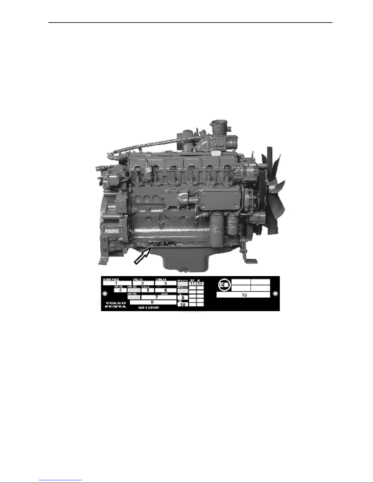
1. Engine model
2. Engine specification number
3. Engine serial number (10 digits)
4. Engine output without fan
5. Rated engine speed
6. Injection timing and type of camshaft
7. Manufacturers identification code
8. Indication of standard and /or regulation
9. ISO 3046, reference test conditions
10. ISO 3046, reference test conditions
11. Injection pump code (EP code)
12. Piston class
13. Prime output, without fan, at rated speed
Identification plates
Location of identification
plates (420-620, 520-722)
Each engine is supplied with two identical identification plates, of which one is mounted on the right side
of the cylinder block and the other one should be mounted in a suitable location adjacent to the engine.
10
General Information Group 20
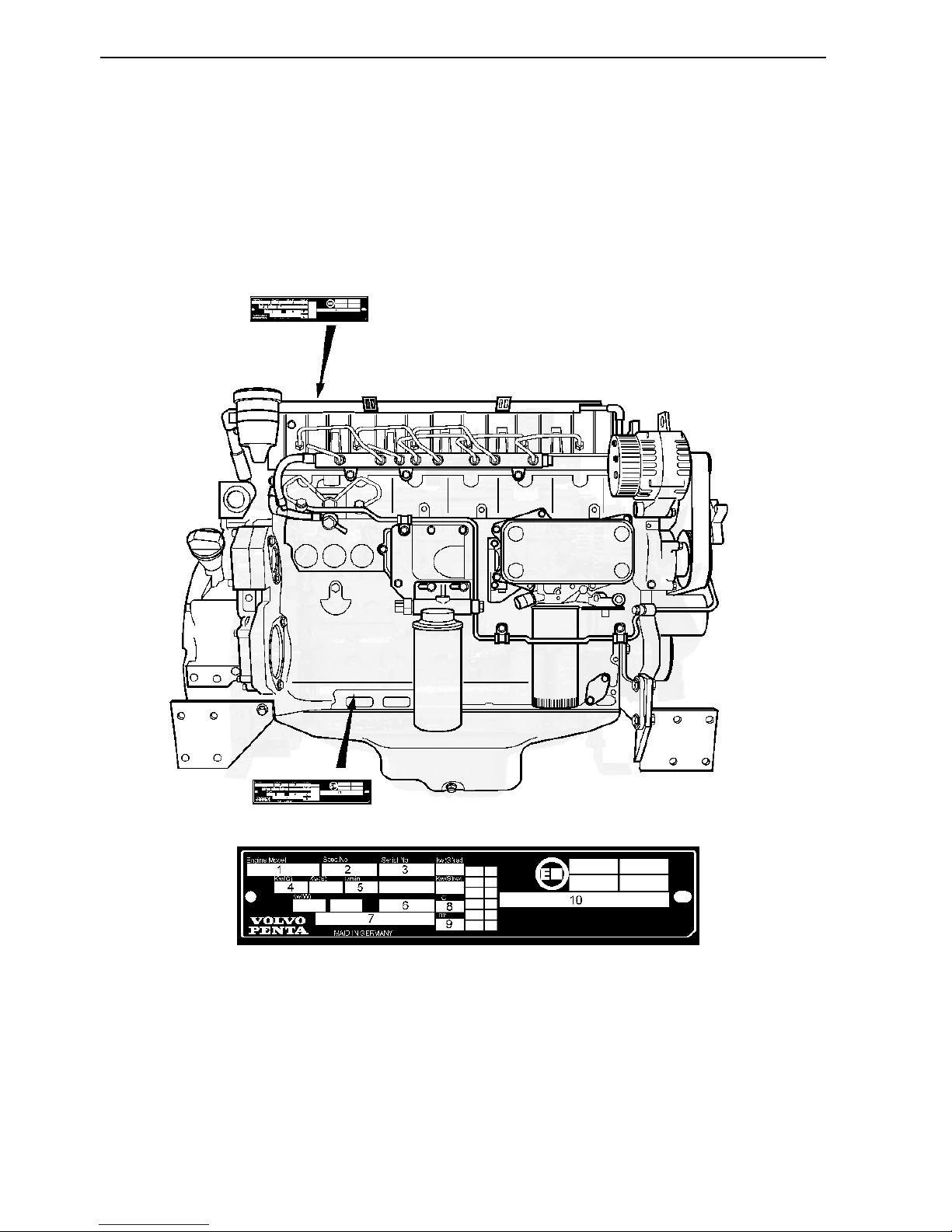
1. Engine model
2. Engine specification number
3. Engine serial number (10 digits)
4. Engine output, without fan
5. Rated engine speed
6. Engine code (linked to EPA/EU Tier III approval)
7. Rated power, standard (peak power according to
Tier III)
8. Air temperature in °C (°F), in accordance with
ISO 3046
9. Altitude above mean sea level, in accordance with
ISO 3046
10. EU Tier III approval number
Identification plates
Location of identification
plates (TAD650/660, 750/760)
Each engine is supplied with two identical identification plates, of which one is mounted on the right side
of the cylinder block and the other one is mounted up
on the valve cover.
Technical data: TD/TAD420VE, TAD620VE, TAD650VE, TAD660VE
11
Group 20
General
Type designation .................................................... TD420VE TAD420VE TAD620VE
Rotation direction, facing flywheel: .........................Counterclockwise
Number of cylinders ............................................... 4 4 6
Bore, mm (inch) .....................................................101 (3.97") 101 (3.97") 98 (3.97")
Stroke, mm (inch) .................................................. 126 (4.96") 126 (4.96") 126 (4.96")
Displacement, dm3 (inch3) ....................................... 4.04 (246.5) 4.04 (246.5) 5.7 (347.8)
Number of valves ...................................................8 8 12
Compression ratio:
EPA 1 .................................................................19:1 19:1 18.4:1
COM 2 ................................................................ 19:1 19:1 18.4:1
Firing sequence ..................................................... 1-3-4-2 1-3-4-2 1-5-3-6-2-4
Engine performance at 2500 rpm, kW (hp) ............. 75 (102)
1, 3)
103 (140)
1, 3)
155 (209)
1, 3)
Max torque, Nm (lbf.ft) ........................................... 390 (288)
3)
493 (364)
3)
700 (516)
3)
At speed, rpm ..................................................... 1500 1500 1500
Low idle, rpm ......................................................... 800 800 800
Max, full load speed, rpm .......................................2000 – 25001)2000 – 25001)2000 – 2500
1)
Weight. engine (dry) kg (lb) .................................... 380 (838)
2)
380 (838)
2)
495 (1091)
2)
1)
See identification plate for correct specification
2)
Weight according to DIN 70020-A
3)
See ”General information, Power standards”.
Technical Data
TD420VE, TAD420VE, TAD620VE, TAD650VE, TAD660VE

Technical data: TD/TAD420VE, TAD620VE, TAD650VE, TAD660VE
12
Group 20
General
Type designation .................................................... TAD650VE TAD660VE
Rotation direction, facing flywheel: .........................Counterclockwise Counterclockwise
Number of cylinders ............................................... 6 6
Bore, mm (inch) .....................................................101 (3.97") 98 (3.85")
Stroke, mm (inch) .................................................. 126 (4.96") 126 (4.96")
Displacement, dm3 (inch3) ....................................... 5.7 (347.8) 5.7 (347.8)
Number of valves ...................................................12 12
Compression ratio: ................................................. 18.4:1 18.4:1
Firing sequence ..................................................... 1-5-3-6-2-4 1-5-3-6-2-4
Engine performance at 2300 rpm, kW (hp) ............. 147 (200)
1, 3)
147 (200)
1, 3)
Max torque, Nm (lbf.ft) ........................................... 750 (553)
3)
800 (590)
3)
At speed, rpm ..................................................... 1600 1600
Low idle, rpm.......................................................... 600-800 600-800
Max, full load speed, rpm ....................................... 2400
1)
2400565
Weight. engine (dry) kg (lb) .................................... 565 (1246)
2)
565 (1246)
2)
Weight. engine (wet) kg (lb) ....................................585 (1290)
2)
585 (1290)
2)
1)
See identification plate for correct specification
2)
Weight according to DIN 70020-A
3)
See ”General information, Power standards”.
Engine block
Cylinder head
Type ...................................................................... Common cylinder head
Max surface unevenness ....................................... 0.1 mm (0.0039")
Cylinder head bolts
Thread size ............................................................ M 12
Quantity and length:
TD420VE/TAD420VE .......................................... 13 x 108 mm (13 x 4.3")
TD420VE/TAD420VE .......................................... 5 x 178 mm (5 x 7")
Quantity and length:
TAD620VE, TAD650/660VE ............................... 19 x 108 mm (19 x 4.3")
TAD620VE, TAD650/660VE ............................... 7 x 178 mm (7 x 7")
Technical data: TD/TAD420VE, TAD620VE, TAD650VE, TAD660VE
13
Group 20
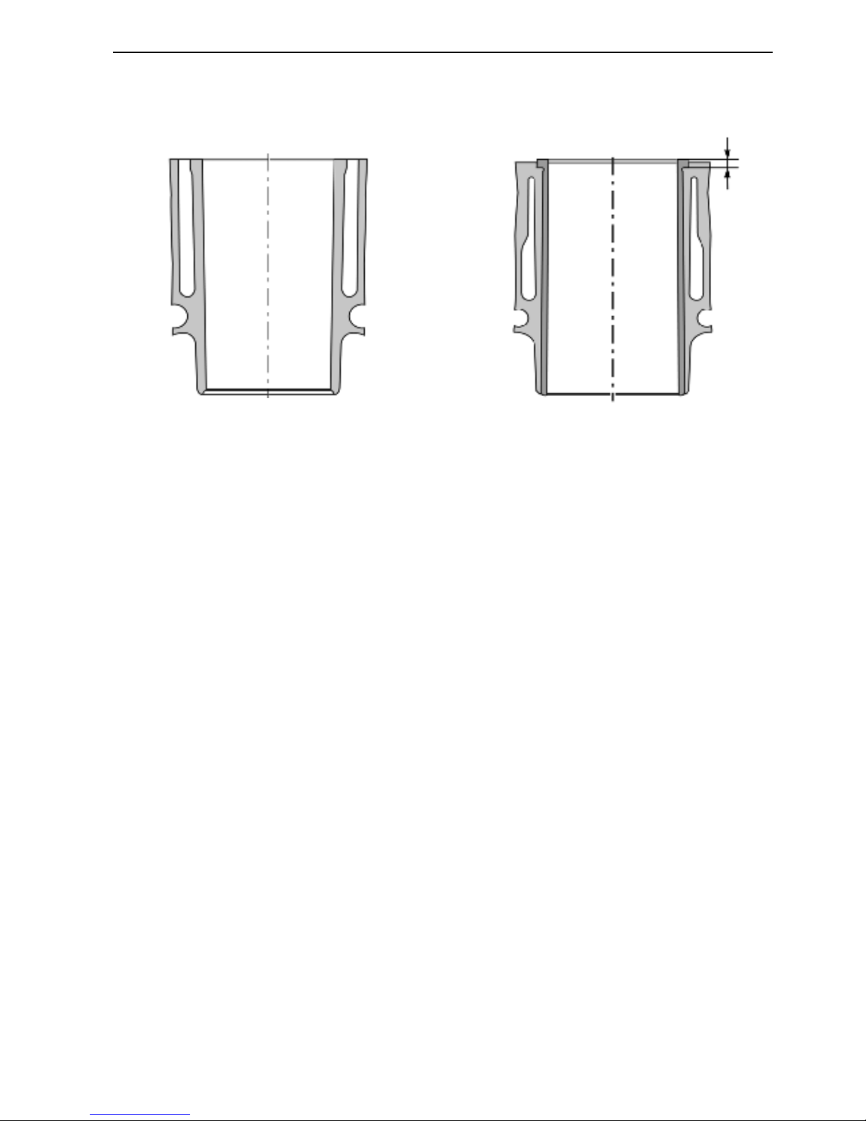
Type:
TD420VE/TAD420VE/TAD650VE ....................... Parent bore
TAD620VE/TAD660VE ....................................... Dry, replaceable
Bore:
TD420VE/TAD420VE/TAD650VE ....................... 101
+0.02
mm (3.976"
+0.00078"
)
TAD620VE/TAD660VE ....................................... 98
+0.02
mm (3.858"
+0.00078"
)
Max bore wear:
TD420VE/TAD420VE/TAD650VE ....................... 101.1 mm (3.98")
TAD620VE .......................................................... 98.1 mm (3.86")
TAD660VE .......................................................... 98.1 mm (3.86")
Sealing surface: Height, see picture (A):
TAD620VE/TAD660VE ....................................... 4.5
-0.02
mm (0.177"
-0.0008"
)
Liner collar seating depth in block:
TAD620VE/TAD660VE ....................................... 4.38
+0.03
mm (0.1724"
+0.0012"
)
Projection of liner above block surface:
TAD620VE/TAD650/TAD660VE .......................... 0.012 – 0.07 mm (0.00047"– 0.0027")
Parent bore
TD420VE, TAD420VE
TAD650VE
Replaceable, dry
TAD620,
TAD660VE
Cylinder liners
A

Technical data: TD/TAD420VE, TAD620VE, TAD650VE, TAD660VE
14
Group 20
• Set the dial gauge in the level of the crankcase surface to ”zero”.
• Position the dial gauge at the measuring points A and B on the top of the piston,
inline with the gudgeon pin.
• Measuring points between A and B on each piston is the distance X.
• Measure all pistons.
• Determine the maximum projection on each piston.
The highest piston projection number, determines the thickness of the cylinder head
gasket. The different head gaskets are identified by the hole identification on each of
the three different thickness available, see picture below.
Measuring points, distance X: ............................. Ø 90 mm (3.5")
Cylinder head gasket
Measuring piston projection
A dial gauge with a fixture (special tool: 999 8678) is needed to measure
the piston projection. The piston is in its TDC above the block surface.
Identification
1 Hole ....................................................................0.33 – 0.55 mm (0.012" – 0.021")
2 Holes .................................................................. 0.56 – 0.65 mm (0.022" – 0.025")
3 Holes .................................................................. 0.66 – 0.76 mm (0.026" – 0.03")
Technical data: TD/TAD420VE, TAD620VE, TAD650VE, TAD660VE
15
Group 20
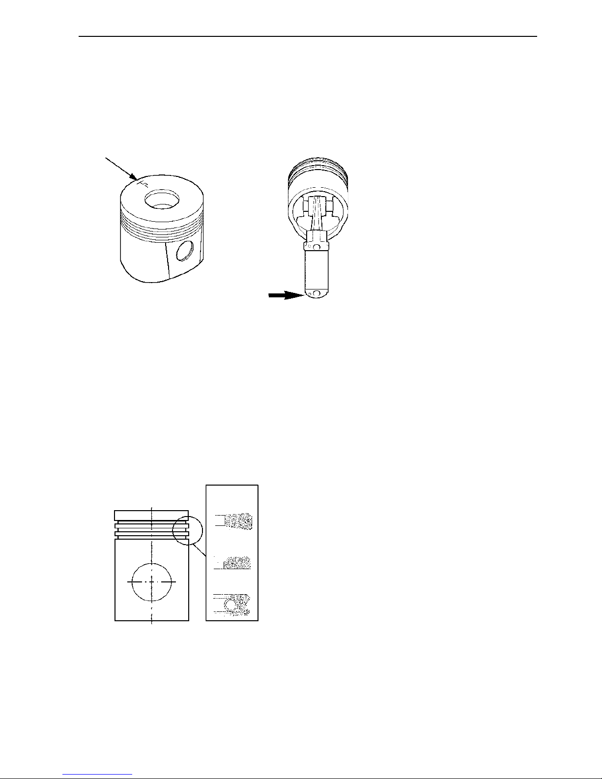
Piston rings
Compression rings
Number of rings ..................................................... 2
Piston ring clearance measured in groove, wear limit:
Upper compression ring (1) ................................. Keystone
Lower compression ring (2) ................................. 0.17 mm (0.067")
Piston ring gap measured in ring opening, wear limit:
Upper compression ring (1) ................................. 0.8 mm (0.03")
Lower compression ring (2) ................................. 2.5 mm (0.0984")
Oilscraper ring (3)
Number: ................................................................. 1
Width, including springcoil: ..................................... 3 mm (0.12")
Piston ring clearance, height: ................................. 0.1 mm (0.0039")
Piston ring gap, wear limit: ..................................... 1.15 mm (0.045”)
Pistons
Number of piston ring grooves ................................ 3
Combustion chamber:
Diameter Ø ......................................................... 61
±0.1
mm (2.402"
±0.0039
”)
Combustion chamber depth:
TD420VE/TAD420VE .......................................... 18
±0.1
mm (0.7087"
±0.0039
”)
TAD620VE, TAD650/TAD660VE ........................ 17.5
±0.1
mm (0.689"
±0.0039
”)
Gudgeon pin diameter Ø ........................................ 38
-0.006
mm (1.496"
-0.0002"
)
Piston front marking, according to picture: Flywheel symbol on the piston top faces the flywheel.
Guiding pins on the connecting rod, must face flywheel symbol on the piston.
1
2
3
Technical data: TD/TAD420VE, TAD620VE, TAD650VE, TAD660VE
16
Group 20
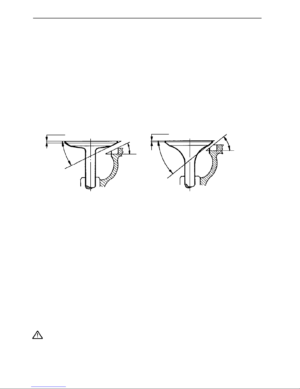
Valve disc edge:
Inlet, min ............................................................. 1.8 mm (0.071")
Exhaust, min ...................................................... 1.1 mm (0.043")
Seat angle, cylinder head:
Inlet .................................................................... 30°
Exhaust .............................................................. 45°
Valve seat width, max:
Inlet, min ............................................................. 2.7 mm (0.106")
Exhaust, min ....................................................... 2.1 mm (0.083")
Valve mechanism
Valves
Disc diameter Ø:
Inlet .................................................................... 41.7
±0.1
mm (1.642"
±0.004"
)
Exhaust .............................................................. 35.9
±0.1
mm (1.413"
±0.004"
)
Stem diameter Ø:
Inlet .................................................................... 7.98
-0.015
mm (0.3142"
-0.0006"
)
Exhaust .............................................................. 7.96
-0.015
mm (0.3134"
-0.0006"
)
Valve seat angle:
Inlet, min ............................................................. 29.5°
Exhaust, min ....................................................... 44.5°
Min 1.8 mm Min 1.1 mm
45°
30°
29.5°
44.5°
Valve clearance (not apply for TAD660VE)
Inlet .................................................................... 0.35
±0.05
mm (0.014"
±0.002"
)
Exhaust .............................................................. 0.55
±0.05
mm (0.022"
±0.002"
)
Important! Control and adjusting of valve clearance is done with an engine oil
temperature between 20 – 80°C (68 – 176°F)
Technical data: TD/TAD420VE, TAD620VE, TAD650VE, TAD660VE
17
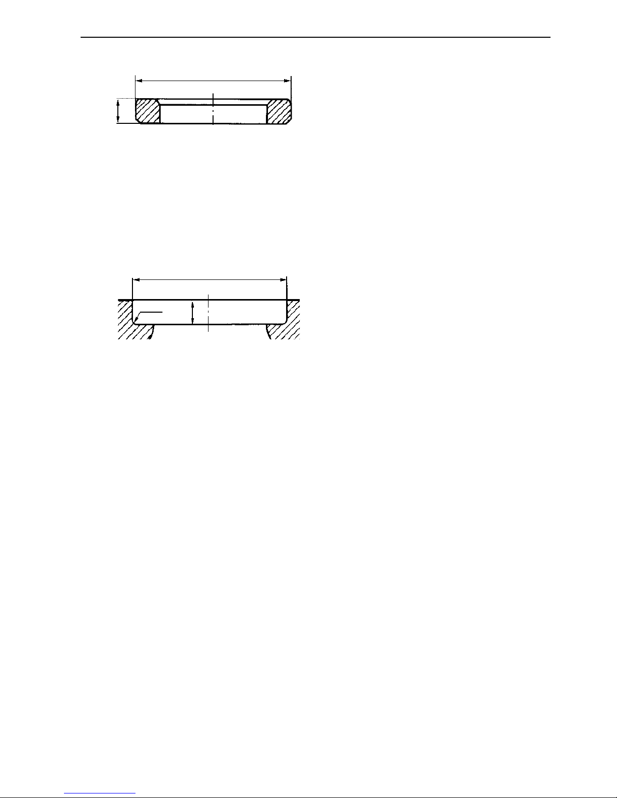
Group 20
Diameter Ø (C), standard:
Inlet .................................................................... 42.7
-0.025
mm (1.681"
-0.001"
)
Exhaust .............................................................. 36.9
-0.025
mm (1.453"
-0.001"
)
Depth (D):
Inlet/Exhaust ...................................................... 10+1 mm (0.4"
+0.04"
)
Seat bottom radius (R):
Inlet/Exhaust ...................................................... 1
-0.3
mm (0.04"
-0.0118"
)
Measurement between valve disc and cylinder head face:
Inlet/Exhaust ...................................................... Min 1.4 mm (0.055")
Valve guides
Inner diameter Ø:
Inlet/Exhaust ...................................................... 8.008
+0.0025
mm (0.3153"
0.00098"
)
Wear limit valve stem – guide:
Inlet .................................................................... 0.1 mm (0.0039")
Exhaust .............................................................. 0.13 mm (0.0051")
Valve springs
Type: ..................................................................... Single
Length: Unloaded: .................................................. 59
±1.9
mm (2.323"
±0.075"
)
Wire diameter Ø: .................................................... 4
±0.03
mm (0.16"
±0.001"
)
Ø A
B
Ø C
R
D
Outer diameter Ø (A), standard:
Inlet .................................................................... 42.79
-0.02
mm (1.685"
-0.0008"
)
Exhaust .............................................................. 36.99
-0.02
mm (1.456"
-0.0008"
)
Height (B):
Inlet .................................................................... 6.8
±0.1
mm (0.2677"
±0.004
)
Exhaust .............................................................. 7.5
±0.1
mm (0.2953"
±0.004
)
Valve seats
Valve seat location
Technical data: TD/TAD420VE, TAD620VE, TAD650VE, TAD660VE
18
Group 20
Flywheel
Type of flywheel, standard :
TD/TAD420,620,650,660VE ................................ Clutch 10" or 11.5"
Max, permitted axial runout
Measuring radius 150 mm (5.91") ........................ 0.1 mm (0.004")
Number of teeth on flywheel ................................... 129
Camshaft
Type of camshaft: .................................................. Three different types: K, L or H
Drive ...................................................................... Gear
Number of bearings:
TD420VE/TAD420VE .......................................... 5
TAD620VE, TAD650/TAD660VE ........................ 7
Inner diameter Ø, bearing journals
Standard ............................................................. 63
+0.054
mm (2.48"
+0.0021"
)
Wear limit ........................................................... 63.08 mm (2.483")
Camshaft bearing thickness: max .......................... 1.388
+0.012
mm (0.05465"
+0.0005"
)
Axial clearance ...................................................... 0.1-0.5 mm (0.004-0.02")
Radial clearance .................................................... 0.05-0.124 mm (0.002-0.0049")
Position of bearing bush at flywheel end ................ 3
+0.2
mm (0.118"
+0.008"
)
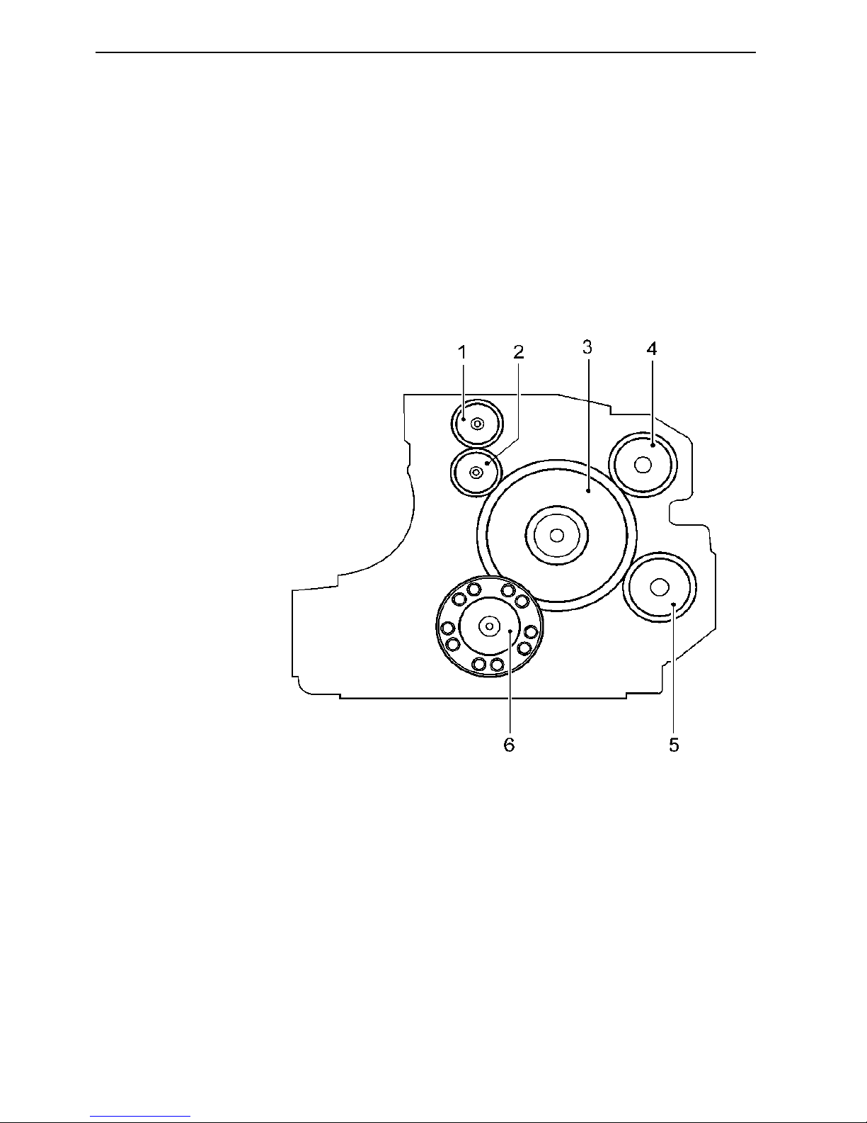
Timing gear
1. Governor drive (not apply for 650/660)
2. Idler gear (not apply for 650/660)
3. Camshaft gear
4. PTO gear B-C (not apply for 650/660)
5. PTO gear A (not apply for 650/660)
6. Crankshaft
Technical data: TD/TAD420VE, TAD620VE, TAD650VE, TAD660VE
19
Group 20
Crank mechanism
Crankshaft length:
TD420VE/TAD420VE .......................................... 618.8 mm (24.36")
TAD620VE, TAD650/TAD660VE ........................ 846.8 mm (33.34")
Crankshaft axial clearance1)................................... 0.1-0.3 mm (0.0039"– 0.0118")
Main bearing radial clearance1)............................... 0.03
+0.062
mm (0.0012"
+0.0024"
)
Max, permissible ovality of main
bearing and crank pins ........................................ 0.01 mm (0.0004")
Max, run-out of center bearing: .............................. 0.1 mm (0.0039"
1)
Important! The dimensions apply to oiled parts
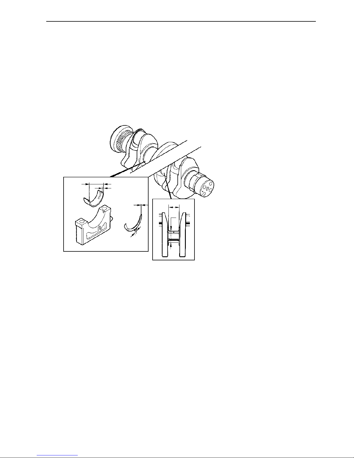
Main bearing journals
Diameter for machining (A): Standard..................... 84
-0.02
mm (2.9134"
-0.0008
)
Undersize:
0.25 mm (0.01") .................................................. 83.75
-0.02
mm (3.2972"
-0.0008
)
Main bearing journals:
Out-of-round: Max. .............................................. 0.01 mm (0.0004")
Taper: Max. ........................................................ 0.01 mm (0.0004")
Width, axial bearing journal (B): Standard ............... 32.2
+0.04
mm (1.1268"
+0.0016"
)
Oversize:
0.4 mm (0.0157") ................................................ 32.6
+0.04
(1.283"
+0.0016"
)
Thrust washers (axial bearing)
Width (C): Standard ................................................ 2
+0.1
mm (0.079"
+0.004"
)
Oversize:
0.2 mm (0.0079") ................................................ 2.2
+0.1
mm (0.087"
+0.004"
)
Width (D):............................................................... 14 mm (0.55")
Main bearing shells
Type: ..................................................................... Replaceable
Inner diameter Ø (E): ............................................. 84.03
+0.042
mm (3.308"
+0.0017"
)
Thickness (F): Standard ......................................... 2.475
+0.01
mm (2.903"-2.903")
Oversize:
0.25 mm (0.01") .................................................. 2.6
+0.01
mm (0.1024"
+0.0004"
)
B
C
D
E
F
A
Technical data: TD/TAD420VE, TAD620VE, TAD650VE, TAD660VE
20
Group 20
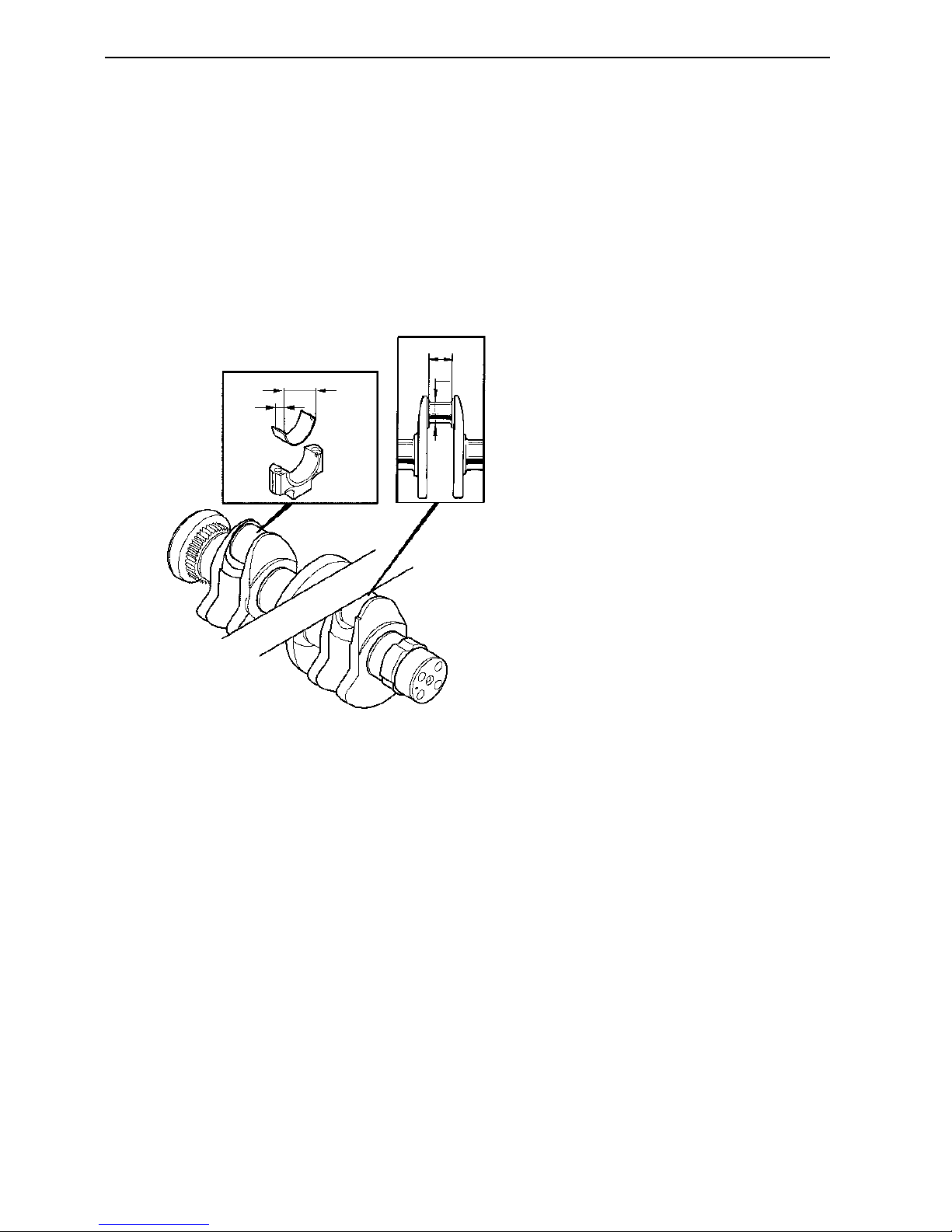
Connecting rod bearing journals
Diameter Ø for machining (G):
Standard ................................................................ 62.994
-0.02
mm (2.48"
-0.0008”
)
Undersize:
0.25 mm (0.01") .................................................. 62.744
-0.02
mm (2.4714"
-0.0008”
)
Width, axial bearing journal (H): ............................. 35.7
±0.02
mm (1.4"
±0.0008"
)
Connecting rod-bearing journals:
Out-of-round: Max. .............................................. 0.01 mm (0.0004")
Taper: Max ......................................................... 0.01 mm (0.0004")
Connecting rod bearing shells
Innerdiameter Ø, bearing (J): .................................. 63.026
+0.039
mm (2.442"
+0.00154”
)
Oversize:
0.25 mm (0.01") .................................................. 62.724
+0.02
mm (2.4716"
+0.00079”
)
Thickness (K): Standard ........................................ 1.777
+0.01
mm (0.06996
+0.0004”
)
Inside bore .......................................................... 66.6
+0.02
mm (2.622"
0.0008"
)
J
K
H
G
Technical data: TD/TAD420VE, TAD620VE, TAD650VE, TAD660VE
21
Group 20
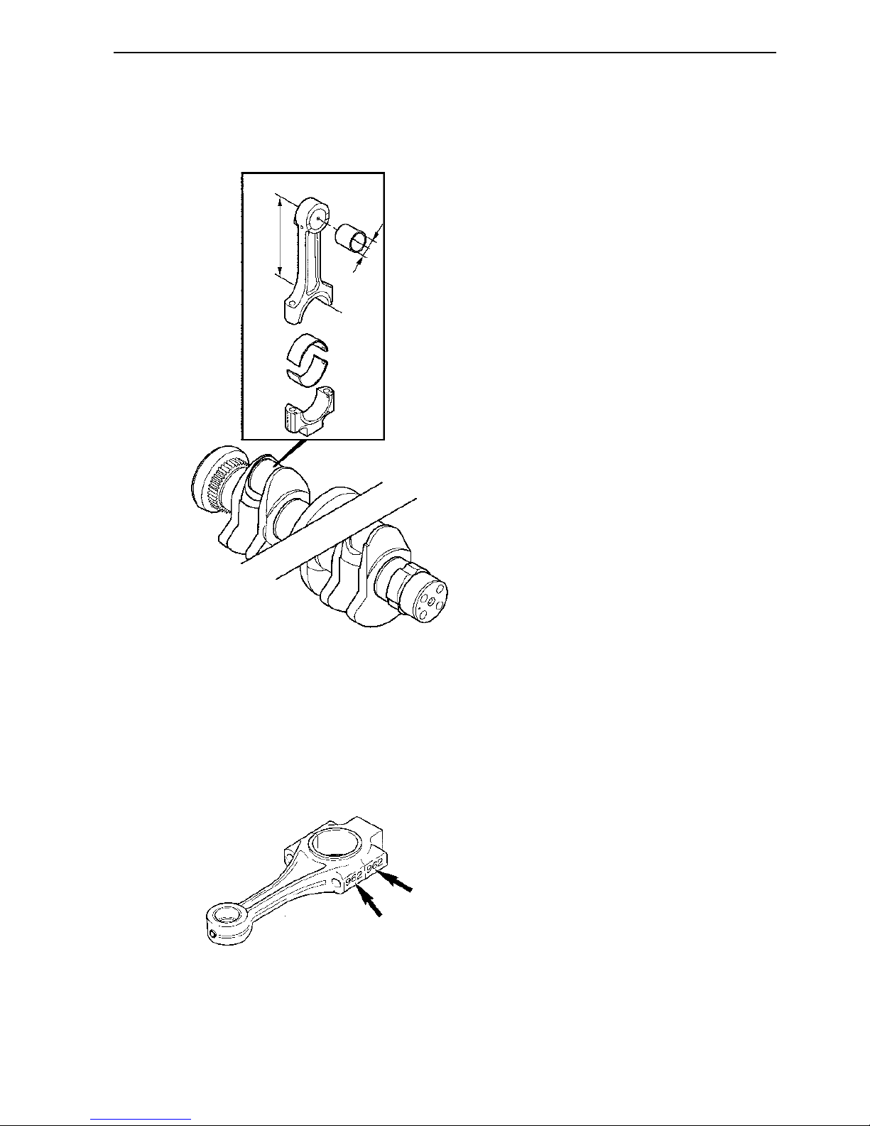
Connecting rods
Length (L): Center – Center .................................... 192
±0.02
mm (7.559"
-0.0008”
)
Connecting rod bushing bore (M): ........................... 38.025
+0.01
mm (1.497"
+0.0004”
)
Wear limit ............................................................ 0.08 mm (0.0031")
Axial clearance, connecting rod – crankshaft1)....... 0.2-0.3 mm (0.00787"-0.0118")
Connecting rod bearing: radial clearance1).............. 0.03-0.09 mm (0.00118"-0.00354")
Parallelism: Tolerans
Over a length of 100 mm..................................... 0.05 mm (0.002")
Squareness: Tolerans
Over a length of 100 mm .................................... 0.05 mm (0.002")
1)
Important! The dimensions apply to oiled parts.
L
M
Connecting rod marking:
Connecting rod and cap number marking must be on one side and identical.

Technical data: TD/TAD420VE, TAD620VE, TAD650VE, TAD660VE
22
Group 20
Viscosity
The viscosity should be selected from the adjacent
table.
NOTE! the temperatures refer to constant outside air
temperature. The tabell above refers to synthetic or
synthetic-based oil.
Fuel sulfur content in percent by weight
Lubricating system
Up to 0.5 % 0.5 – 1 % More than 1 %
1)
Oil change interval: In operation whichever reached first
Oil grade
2)
VDS-3, VDS-2
ACEA: E7, E5, E3 500 hours or 12 months 250 hours or 12 months 125 hours or 12 months
API: CI-4, CH-4, CG-4
1)
If the sulfur content is > 1.0% by weight, use oil with TBN > 15
2)
For markets outside Europe, API: CG-4 and CH-4 can be used instead of ACEA: E3.
NOTE! Mineral based oil, either fully or semi-synthetic, can be used on condition that it complies with the quality
requirements above.
NOTE! For 6 and 7-liter engines equipped with low profile type oil pans, the oil change interval must be halved.
VDS = Volvo Drain Specification
ACEA = Association des Constructeurs Européenne d’Automobiles
API = American Petroleum Institute
Global DHD = Global Diesel Heavy Duty
TBN = Total Base Number
Technical data: TD/TAD420VE, TAD620VE, TAD650VE, TAD660VE
23
Group 20
Engine oil quantity
With oil filter:
TD420VE/TAD420VE .......................................... 10 liter (2.64 US gal)
TAD620VE, TAD650/TAD660VE ........................ 16 liter (4.22 US gal)
TD420VE/TAD420VE TAD620VE, TAD650VE, TAD660VE
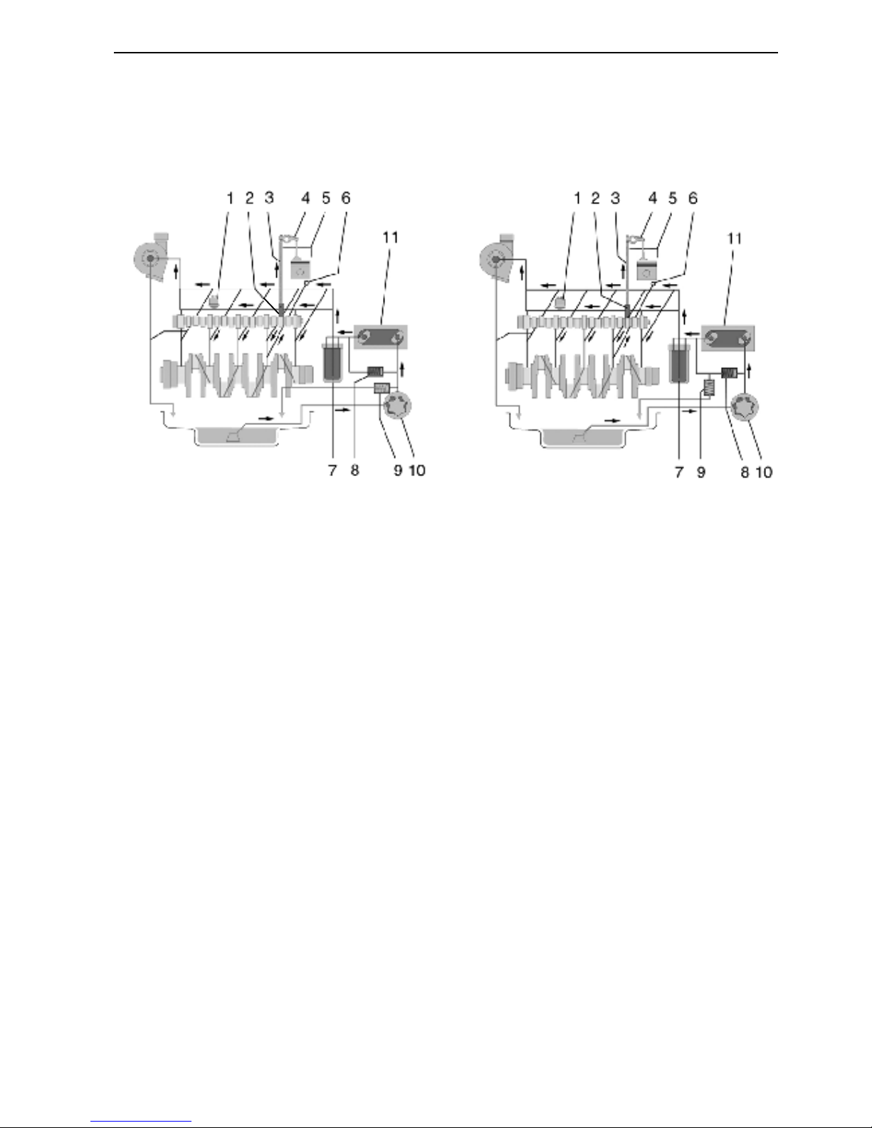
1. Oil pressure sensor
Oil pressure, at operation temperature, min 120°C (248°F)
At rated speed:
TD420VE/TAD420VE .......................................... 400 kPa (58 psi)
TAD620VE, TAD650/TAD660VE ........................ 370 kPa (53.7 psi)
At idle speed (800 rpm), min .................................. 80 kPa (11.6 psi)
Shut down switch, at pressure lower than: ............. 50 kPa (7.2 psi)
2. Tappet with pulse lubrication
3. Pushrod, oil supply for rocker arm lubrication
4. Rocker arm
5. Return line to oil sump
6. Piston cooling .................................................. 2-hole nozzles for each cylinder
7. Oil filter, full-flow
Filtering size ....................................................... 0.012 mm (0.0005")
By-pass valve oil filter
Opening pressure ................................................250
±50
kPa (35±7 psi)
8.By-pass valve oil cooler:
Opening pressure ................................................210
±30
kPa (30.5±4 psi)
9. Safety valve, opening pressure:
TD420VE/TAD420VE .......................................... 600
±75
kPa (87
±10.7
psi)
TD620VE, TAD650/TAD660VE ........................... 400
±40
kPa (58±2 psi)
10. Lube oil pump
Type ...................................................................... Rotary pump driven by the crankshaft
Rotary pump width:
TD420VE/TAD420VE .......................................... 12.3 mm (0.48")
TD620VE, TAD650/TAD660VE ........................... 16.5 mm (0.65")
Oil flow (2500 rpm)
TD420VE/TAD420VE .......................................... 65 l/min (17 US gal/hour)
TD620VE, TAD650/TAD660VE ........................... 90 l/min (24 US gal/hour)
11. Oil cooler
Normal oil temperature: .......................................... 80°C (176°F)
Max oil temperature: ..............................................125°C (257°F)
Technical data: TD/TAD420VE, TAD620VE, TAD650VE, TAD660VE
24
Group 20
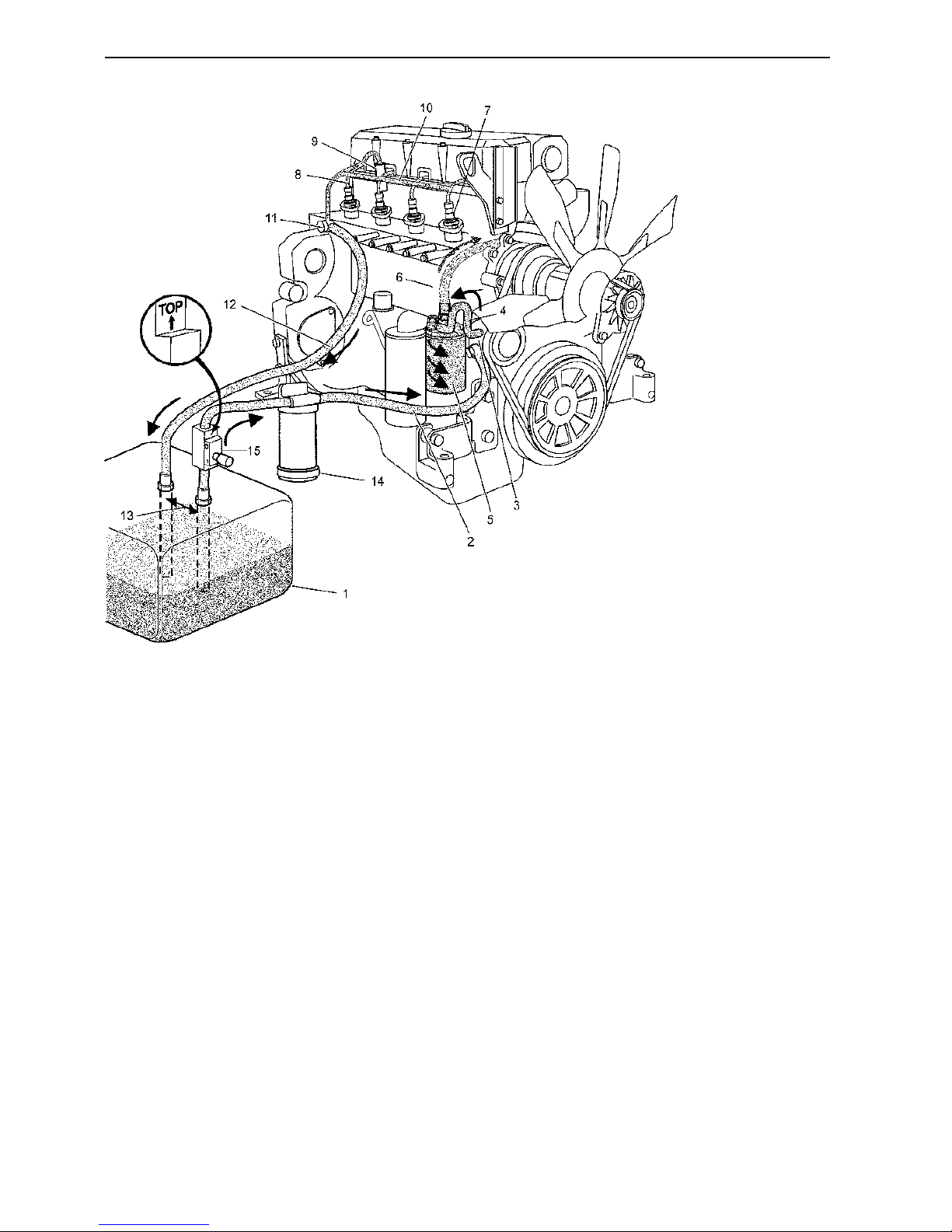
1. Fuel tank.
Max height above fuel pump. 2 meter (6.5 ft)
Max suction height to fuel pump. 1.5 meter (4.9 ft)
2. Fuel line (to pump).
Inside diameter. min 12 mm (0.47")
1)
3. Fuel pump
4. Line to fuel filter.
Inside diameter. min 12 mm (0.47")
1)
5. Fuel filter
6. Fuel line (to fuel duct).
7. Injection pumps, 420/520 (4) 620/720/721 (6)
8. Delivery pipe to injector.
9. Injector
10. Fuel return line
11. Overflow valve
2)
12. Return fuel line to fuel tank.
Inside diameter, min 10 mm (0.39")
1)
13. Fuel pipes, minimum distance 300 mm (11.8")
14. Pre-filter for water separating
15. Hand pump (accessory)
1)
Depending on length of hose.
2)
Used for bleeding.
Fuel system (420, 620)
Technical data: TD/TAD420VE, TAD620VE, TAD650VE, TAD660VE
25
Group 20
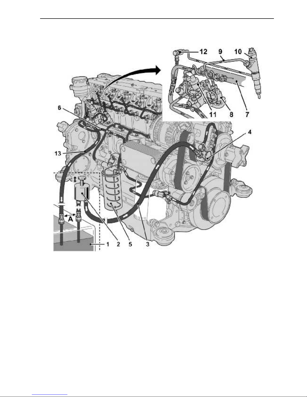
1. Fuel tank
2. Hand pump (accessory)
3. Fuel line (to pump)
4. Fuel pump
5. Fuel filter
6. Pipe to highpressure
7. Rail
8. Highpressure pump
9. Fuelpipe, to injector
10. Injector
11. M-prop
12. Pressurevalve
13. Return fuel line, to fuel tank, A = Fuel pipes,
minimum distance 300 mm (11.8")
Fuel system (650, 660)
Technical data: TD/TAD420VE, TAD620VE, TAD650VE, TAD660VE
26
Group 20
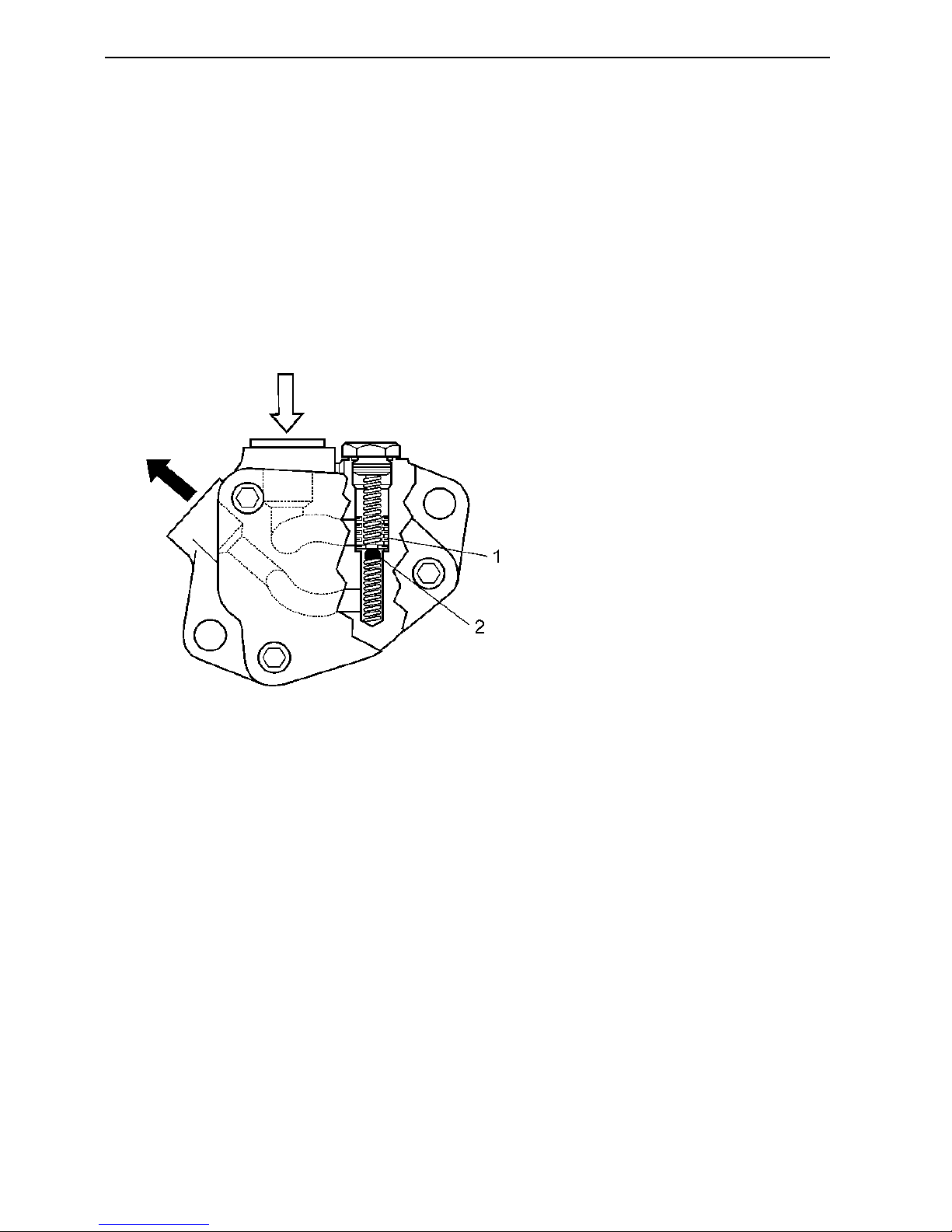
Fuel feed pump
Fuel system figures are corresponding to the picture above.
1. Overpressure relief valve:
Opening pressure ................................................ 0.6
±0.05
MPa (87±7 psi)
1)
2. Bypass valve:
Opening pressure ................................................ 50±5 kPa (7.2
±0.7
psi)
Fuel flow:
Min fuel flow at 1500 rpm. ...................................... 600 l/hour (158.5 gal/hour)
Firing sequence
TD420VE/TAD420VE .......................................... 1-3-4-2
TAD620VE/TAD650VE/TAD660VE ..................... 1-5-3-6-2-4
Feed pressure ........................................................ 0.5 MPa (72.5 psi)
Feed pressure after fuel filter
At 1500 rpm: Min ................................................ 0.28 MPa (40.6 psi)
In
Out
Fuel specification
The fuel must be approved according to national and international standards for commercial fuels for example:
EN 590 (With environmental and sub-zero temperature specifications according to national requirements)
ASTM D 975 No 1-D and 2-D
JIS KK 2204
Sulfur content: According to current legislation in each country.
NOTE! Fuels with extremely low sulfur contents (ex City diesel in Sweden and Finland) can cause a drop in power
output of 5% and an increase in fuel consumption of 2–3%.
 Loading...