

Page 1

OPERATOR’S MANUAL
TAMD63L/P, TAMD74A
Page 2
CALIFORNIA
Proposition 65 Warning
Diesel engine exhaust and some of its constituents are known
to the State of California to cause cancer, birth defects, and
other reproductive harm.
This operator’s manual is also available in the following languages:
Diese Betriebsanleitung ist auch auf
Deutsch erhältlich.
Ein Bestellcoupon ist am Ende der Betriebsanleitung zu finden.
Ce manuel d’instructions peut être
commandé en français.
Vous trouverez un bon de commande à la fin
du manuel d’instructions.
Este libro de instrucciones puede solicitarse en español.
El cupón de pedido se encuentra al final del
libro.
Den här instruktionsboken kan beställas på svenska.
Beställningskupong finns i slutet av instruktionsboken.
Questo manuale d’istruzioni può essere ordinato in lingua italiana.
Il tagliando per l’ordinazione è riportato alla
fine del manuale.
Dit instructieboek kan worden besteld
in het Nederlands.
De bestelcoupon vindt u achter in het instructieboek.
Denne instruktionsbog kan bestilles
på dansk.
Bestillingskupon findes i slutningen af instruktionsbogen.
Tämän ohjekirjan voi tilata myös suomenkielisenä.
Tilauskuponki on ohjekirjan lopussa.
Este manual de instruções pode ser
encomendado em português.
O talão de requerimento encontra-se no fim
do manual.
Бхфь фп егчейсЯдйп чсЮузт
дйбфЯиефбй уфзн бгглйкЮ глюууб.
Гйб нб рбсбггеЯлефе Энб бнфЯфхрп,
ухмрлзсюуфе фз цьсмб рпх всЯукефбй уфп
фЭлпт бхфпэ фпх егчейсйдЯпх чсЮузт.
Page 3
Foreword
Volvo Penta marine engines are used all over the world today. They are used in all
possible operating conditions for professional as well as leisure purposes. That’s not
surprising.
After more than 90 years as an engine manufacturer and after delivering over
500,000 marine engines, the Volvo Penta name has become a symbol of reliability,
technical innovation, top of the range performance and long service life. We also believe that this is what you demand and expect of your Volvo Penta engine.
We would like you to read this operator’s manual thoroughly and consider the advice
we give on running and maintenance before you cast off on your maiden voyage so
that you will be ensured of fulfilling your expectations.
With warm regards
AB VOLVO PENTA
IMPORTANT! These instructions do not contain descriptions of controls or
operation for boats with waterjet. If your boat is equipped with Volvo Penta
waterjet, this information can be found in the operator’s manual that came
with the waterjet.
Page 4

2
Contents
Safety information .............................................. 3
Boat trips ............................................................ 4
Maintenance and service.................................... 6
Introduction ........................................................ 8
Environmental responsibility ............................... 8
Running in .......................................................... 8
Fuel and oil......................................................... 8
Service and spare parts...................................... 8
Certified engines................................................. 9
Warranty............................................................. 9
Identification number .......................................... 11
Presentation........................................................ 11
Instruments......................................................... 13
Instrument panels ............................................... 13
Control panels .................................................... 14
Warning displays ................................................ 14
Starting switch .................................................... 15
Controls............................................................... 16
Single lever control ............................................. 16
Dual lever control................................................ 17
Starting the engine ............................................. 18
Measures before start......................................... 18
Starting procedure .............................................. 18
Operation ............................................................ 20
Check the instruments........................................ 20
Alarms and fault indication.................................. 20
Cruising speed ................................................... 21
Manoeuvring....................................................... 21
Accessories........................................................ 23
Stopping the engine ........................................... 24
Before stopping .................................................. 24
Stop.................................................................... 24
Emergency stop ................................................. 24
After stopping ..................................................... 25
Anti-freezing measures....................................... 25
Breaks in operation............................................. 25
Maintenance schedule ....................................... 26
Maintenance........................................................ 29
Engine, general .................................................. 29
Lubricating system.............................................. 32
Freshwater system ............................................. 35
Seawater system................................................ 43
Fuel system ........................................................ 47
Electrical system ................................................ 52
Electrical component diagrams........................... 56
Reverse gear...................................................... 58
Inhibiting ............................................................. 60
Troubleshooting ................................................. 62
Start using auxiliary batteries.............................. 63
Technical Data .................................................... 64
Engine ................................................................ 64
Reverse gear...................................................... 65
© 2001 AB VOLVO PENTA
We reserve the right to make revisions. Printed on environment-friendly paper
(Cover: National Administration of Shipping and Navigation, permit 9809095)
Page 5
3
Safety information
Read this chapter thoroughly. It concerns your safety. This section describes how safety information is presented
in this manual and on the product. It also includes a summary of basic safety regulations for boat trips and maintenance of the engine.
Make sure you are in possession of the right operator’s manual before reading on. If this is not the case,
please get in touch with your Volvo Penta dealer.
Incorrect handling can cause personal injury or damage to the product and/or property.
Consequently, please read this operator’s manual thoroughly before starting the engine
or carrying out maintenance and service. If anything is still not clear or if you are not sure
of any points, please get in touch with your Volvo Penta dealer for assistance.
This symbol is used throughout the operator’s manual and on the product to bring your attention to points of safety-related information. Always read such information thoroughly.
Warnings in the operator’s manual have the following order of priority:
WARNING! Warns for the risk of physical injury, severe damage to the product or other
property or serious malfunctions that may occur if the instructions are not followed.
IMPORTANT! Used to call your attention to points that may cause malfunctions or damage
to the product or other property.
NOTE! Used to call your attention to important information that can facilitate working methods or handling.
This symbol is used in certain cases on our products to refer to important information found
in the operator’s manual. Make sure all warning and information symbols on the engine and
transmission are easily visible and legible. Replace symbols that have been damaged or
painted over.
Page 6

4
Safety information
Safety regulations for boat trips
The new boat
Read operator’s manuals and other information accompanying the new boat thoroughly. Accustom
yourself with handling the engine, controls and other
equipment in a safe and correct manner.
If this is your first boat or if it is a type you are not
used to, we recommend practising manoeuvring the
boat in a peaceful environment. Learn the sea-going
and manoeuvring characteristics at different speeds
and in varying weather and load conditions before
casting off on your “real” maiden voyage.
Remember that when operating a boat, you have a
legal responsibility to be aware of and follow regulations concerning traffic and safety at sea. Inform
yourself of the regulations that apply to you and your
waters by getting in touch with the relevant authorities
or marine safety organisation.
Attending some kind of boat handling course is a
good idea. We recommend getting in touch with a regional boat or marine safety organisation to help you
locate a suitable course.
Accidents and other incidents
Sea rescue statistics show that deficient maintenance
of boats and engines together with defective safety
equipment often causes accidents and other incidents
at sea.
Make sure your boat and engine are maintained in
accordance with directions in the operator’s manuals
and that the safety equipment on board is in good
working order.
Daily inspection
Make a habit of visually inspecting the engine and engine room before starting (before starting the en-
gine) and after stopping (when the engine has been
turned off). This will help you to quickly detect any
fuel, coolant or oil leaks and any other abnormalities
that have occurred or are about to occur.
Manoeuvring
Avoid violent and rapid rudder movement and gear
shifting. There is a risk of the passengers falling down
or falling overboard.
A rotating propeller can cause serious injury. Make
sure there is nobody in the water before engaging forward/reverse. Never run close to bathers or in places
where you have reason to believe there are people in
the water.
Filling fuel
There is a risk of fire and explosion when filling fuel.
Smoking is prohibited and the engine must be turned
off.
Never overfill the tank. Close the filler cap securely.
Use only fuel recommended in the operator’s manual.
The incorrect grade of fuel can disturb operation or
cause breakdown. This can also lead to the control
rod jamming on diesel engines, which will overrev the
engine and risk damaging machinery and causing
personal injury.
Do not start the engine
Do not start or run the engine with a suspected fuel or
LPG leak in the boat, nor when you are close to or in
a discharge of explosive media, etc. There is risk for
fire and/or explosion in explosive surroundings.
Page 7
5
Safety information
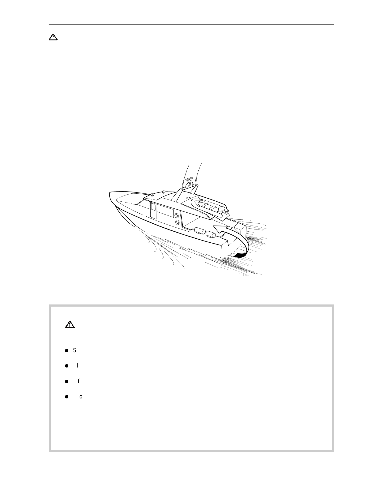
Carbon monoxide poisoning
When a boat is moving forward, it will cause a certain
vacuum to form behind the boat. In unfortunate circumstances, the suction from this vacuum can be so
great that the exhaust gases from the boat are drawn
into the cockpit or cabin and cause carbon monoxide
poisoning.
This problem is most prevailant on high, wide boats
with abrupt stern. In certain conditions, however, this
suction can be a problem on other boats, e.g. when
running with the cover up. Other factors that can increase the effect of the suction are wind conditions,
load distribution, swells, trim, open hatches and portholes, etc.
Most modern boats, however, are designed in such a
way that this problem is very rare. If suction should
arise anyway, do not open hatches or portholes at the
fore of the boat. Surprisingly, this will otherwise increase the suction. Try changing speed, trim or load
distribution instead. Try taking down/opening or in
any other way changing the setup of the cover as
well. Get in touch with your boat dealer for help in obtaining the best solution for your boat.
Remember
Safety equipment: life jackets for everyone on board, communication equipment, distress rockets,
approved fire extinguisher, bandages, life buoy, anchor, paddle, torch, etc.
l
Spare parts and tools: Impeller, fuel filter, fuses, adhesive tape, hose clips, engine oil, propeller
and tools for tasks it may be necessary to perform.
l
Plan your desired route from the charts. Calculate distance and fuel consumption. Listen to
weather reports.
l
Inform relations of your planned route for long trips. Remember to inform of changed plans or delays.
l
Inform the people on board of where the safety equipment is located and how it works. Make sure
there is more than one person on board that knows how to start and manoeuvre the boat safely.
This list should be supplemented with necessary safety equipment depending on the type of boat,
where and how it is being used, etc. We recommend you get in touch with a regional boat or marine
safety organisation to obtain more detailed marine safety information.
Page 8

6
Safety information
Safety directions for maintenance and service
Preparations
Knowledge
The operator’s manual contains directions for performing normal maintenance and service in a safe
and correct manner. Read the directions carefully before starting work.
More detailed service literature is available from your
Volvo Penta dealer.
Never perform a task unless you are absolutely sure
how it is to be carried out, call your Volvo Penta dealer for assistance instead.
Stop the engine
Stop the engine before opening or dismantling the engine hatch/hood. Maintenance and service must be
carried out with the engine stationary unless stated
otherwise in the instructions.
Prevent inadvertent start of the engine by removing
the starter key and turning off the power with the main
switch, locking it in the off position. Place a warning
sign in the driver position stating that service is in
progress.
Working on or approaching a running engine is a
safety hazard. Loose clothing, hair, fingers or a
dropped tool can fasten in rotating parts and cause
serious bodily injury. Volvo Penta recommend leaving
all work requiring the engine to be running to an
authorised Volvo Penta service centre.
Lifting the engine
Always use the lifting eyes mounted on the engine (or
reverse gear) when lifting the engine. Always make
sure lifting equipment is in good condition and constructed for the lift (engine weight together with possible reverse gear and extra equipment). Use an adjustable lifting boom to ensure safe handling when lifting the engine. All chains and wires must run parallel
with each other and as much at right-angle as possible to the top of the engine. Note that any extra equipment mounted on the engine can change the centre
of gravity. Special lifting devices may be required to
obtain the right balance and safe handling. Never perform service on an engine suspended only from a lifting device.
Before starting
Refit all guards and covers that have been removed
before starting the engine. Make sure there are no
tools or other objects left on the engine.
A turbocharged engine must never be started without
the air filter fitted. The rotating compressor wheel in
the turbocharger can cause severe personal injury.
There is also a risk of foreign objects being drawn in
and causing mechanical damage.
Fire and explosion
Fuel and lubricants
All fuel, most lubricants and many chemicals are
flammable substances. Always read and follow the directions on the packaging.
Work performed on the fuel system must be done on
a cold engine. Fuel leaks and spills on hot surfaces or
electrical components can cause fires.
Keep oil- and fuel-drenched rags and other hazardous materials where they are safe in case of fire. Oil
drenched rags can self-ignite in certain conditions.
Never smoke when refuelling, topping up with oil or
when in the vicinity of the fuel station or engine room.
Non-original parts
Components in fuel, ignition and electrical systems on
Volvo Penta engines are designed and manufactured
to minimize the risk of explosion and fire in compliance with existing legislation.
The use of non-original parts can result in explosion
or fire.
Batteries
Batteries contain and generate oxyhydrogen gas, especially when charging. Oxyhydrogen is easily ignited
and extremely explosive.
Smoking, naked flames and sparks must never occur
in or close to the batteries or battery compartment.
A faulty battery connection or jumper cable can generate sparks which can cause the battery to explode.
Start spray
Never use start spray or similar start help. Explosions
can occur in the intake manifold. Risk for personal injury.
Page 9

7
Safety information
Hot surfaces and fluids
A hot engine always involves risk for burn injuries.
Take care with hot surfaces. E.g.: exhaust manifold,
turbocharger, oil pan, charge air pipe, starting heater,
hot coolant and warm lubricant in pipes and hoses.
Carbon monoxide poisoning
Start the engine in well ventilated spaces only. When
running in confined spaces, the exhaust gases and
crankcase gases must be evacuated.
Chemicals
Most chemicals such as glycol, anti-corrosion agent,
preservatives, degreasing agent, etc., are hazardous
to health. Always read and follow the directions on
the packaging.
Certain chemicals such as preservatives are flammable and harmful to inhale. Provide good ventilation
and use breathing protection when spraying. Always
read and follow the directions on the packaging.
Store chemicals and other hazardous materials out of
reach of children. Leave left over or used chemicals
to a destruction plant.
Cooling system
There is a risk of water entering when working on the
seawater system. Therefore, stop the engine and
close the sea cock before starting work.
Avoid opening the coolant filler cap when the engine
is warm. Steam or hot coolant may spurt out and
cause burn injuries.
If the filler cap, coolant pipe, cock, etc., must nevertheless be opened or dismantled while the engine is
warm, the filler cap must be opened carefully to release the pressure before removing it completely and
starting work. Note that the coolant can still be hot
and cause burn injuries.
Lubricating system
Hot oil can cause burn injuries. Avoid skin contact
with warm oil. Make sure the lubricating system is
depressurised before starting work. Never start or run
the engine with the oil filler cap removed or there will
be a risk of the oil being thrown out.
Fuel system
Always protect your hands when carrying out leak detection. Escaping fluids under pressure can pierce
bodily tissue and cause serious injury. Risk of blood
poisoning.
Always cover the alternator if it is located under the
fuel filter. Fuel spills can damage the alternator.
Electrical system
Turn off the power
Before starting work on the electrical system, the engine must be stopped and the powered turned off with
the main switch/switches. Shore power to the engine
heater, battery charger or other extra equipment fitted
to the engine must be disconnected.
Batteries
Batteries contain a highly corrosive electrolyte. Protect your eyes, skin and clothing when charging and
handing batteries. Always use protective goggles and
gloves.
In case of splashes on the skin, wash with soap and
plenty of water. In case of splashes in the eyes, rinse
immediately with plenty of water and call a doctor.
Page 10

8
Introduction
The operator’s manual has been produced to give you the greatest benefit of your Volvo Penta marine engine. It
contains the information necessary to handle and maintain your engine in a safe and correct manner. We would
like you to read this operator’s manual thoroughly and learn how to handle the engine, controls and other equipment in a safe manner before casting off for your maiden voyage.
Keep the operator’s manual handy at all times. Keep it safe and do not forget to hand it over to the new owner if
you ever sell your boat.
Care of the environment
We would all like to live in a clean and healthy environment. Somewhere where we can breathe clean
air, see healthy trees, have clean water in our lakes
and oceans, and are able to enjoy the sunshine without being worried about our health. Unfortunately, this
cannot be taken for granted nowadays but is something we must work together to achieve.
As a manufacturer of marine engines, Volvo Penta
has a special responsibility, why care of the environment is a core value in our product development. Today, Volvo Penta has a broad range of engines where
progress has been made in reducing exhaust emissions, fuel consumption, engine noise, etc.
We hope you will take care in preserving these qualities. Always follow any advice given in the operator’s
manual concerning fuel grades, operation and maintenance and you will avoid causing unnecessary interference to the environment. Get in touch with your
Volvo Penta dealer if you notice any changes such as
increased fuel consumption exhaust smoke.
Adapt speed and distance to avoid wash and noise
disturbing or injuring animal life, moored boats, jetties,
etc. Leave islands and harbours in the same condition as you want to find them. Remember to always
leave hazardous waste such as waste oil, coolant,
paint and wash residue, flat batteries, etc., for disposal at a destruction plant.
Our joint efforts will make a valuable contribution to
our environment.
Running in
The engine must be “run in” during the first 10 hours
of operation as follows:
Run the engine under normal operation. Do not run it
at full power except for short periods. Never run the
engine for long periods at constant rpm during this
time.
A high consumption of lubricant is normal during the
running in period. Therefore, check the oil level more
often than recommended.
The prescribed warranty inspection “First Service Inspection” must be carried out during this first period of
operation. For more information: See Warranty and
Service Book.
Fuel and oil
Use only fuel and oil grades as recommended in the
operator’s manual. Other grades can cause operational problems, increase fuel consumption and have
long-range effects on engine service life.
Always change oil, oil filter and fuel filter according to
prescribed intervals.
Service and spare parts
Volvo Penta marine engines are designed for high
operational reliability and long service life. They are
constructed to withstand the marine environment
while also affecting it as little as possible. Through
regular service and the use of Volvo Penta original
spare parts, these qualities will be retained.
The worldwide Volvo Penta network of authorised
dealers is at your service. They are specialists in
Volvo Penta products and stock accessories, original
spare parts, test equipment and the special tools required to perform high-quality service and repairs.
Always follow the maintenance intervals specified in
the operator’s manual and remember to specify the
engine/transmission number when ordering service
and spare parts.
Page 11
9
Introduction
Certified engines
It is essential that owners and operators of emission
certified engines used in areas where exhaust emissions are regulated by law are aware of the following
points:
A certification involves the engine type being
checked and approved by applicable authorities. Engine manufacturers guarantee that all engines of the
same type correspond with the certified engine.
This puts special demands on the maintenance
and service of your engine:
l
Maintenance and service intervals recommended
by Volvo Penta must be followed.
l
Only Volvo Penta original spare parts may be
used.
l
Service of injector pumps, pump settings and injectors must always be performed at an
authorised Volvo Penta workshop.
l
The engine must not be modified in any way with
the exception of accessories and service kits approved by Volvo Penta for use on the engine.
l
Installation modifications must not be made to the
engine exhaust pipe or inlet channels.
l
Any sealed sections must not be broken by anyone other than authorised personnel.
Otherwise, the general directions concerning running,
care and maintenance given in the operator’s manual
apply.
IMPORTANT! Neglected or deficient maintenance/service and the use of non-original spare
parts will entail Volvo Penta renouncing any responsibility for the engine corresponding to the
certified version. Volvo Penta will not compensate for damage and/or costs arising from the
above.
Warranty
Your new Volvo Penta marine engine is covered by a limited warranty complying with the conditions
and instructions given in the Warranty and Service Book.
Note that AB Volvo Penta’s responsibility is limited to what is specified in the Warranty and Service
Book. Read it carefully as soon as possible after delivery. It contains important information concerning
the warranty card, service, maintenance and what the owner is responsible to be aware of, check and
perform. Warranty liability will otherwise be declined completely or fully by AB Volvo Penta.
Get in touch with your Volvo Penta dealer if you have not received a Warranty and Service Book
or a copy of the warranty card.
Page 12
10
Introduction
Identification number
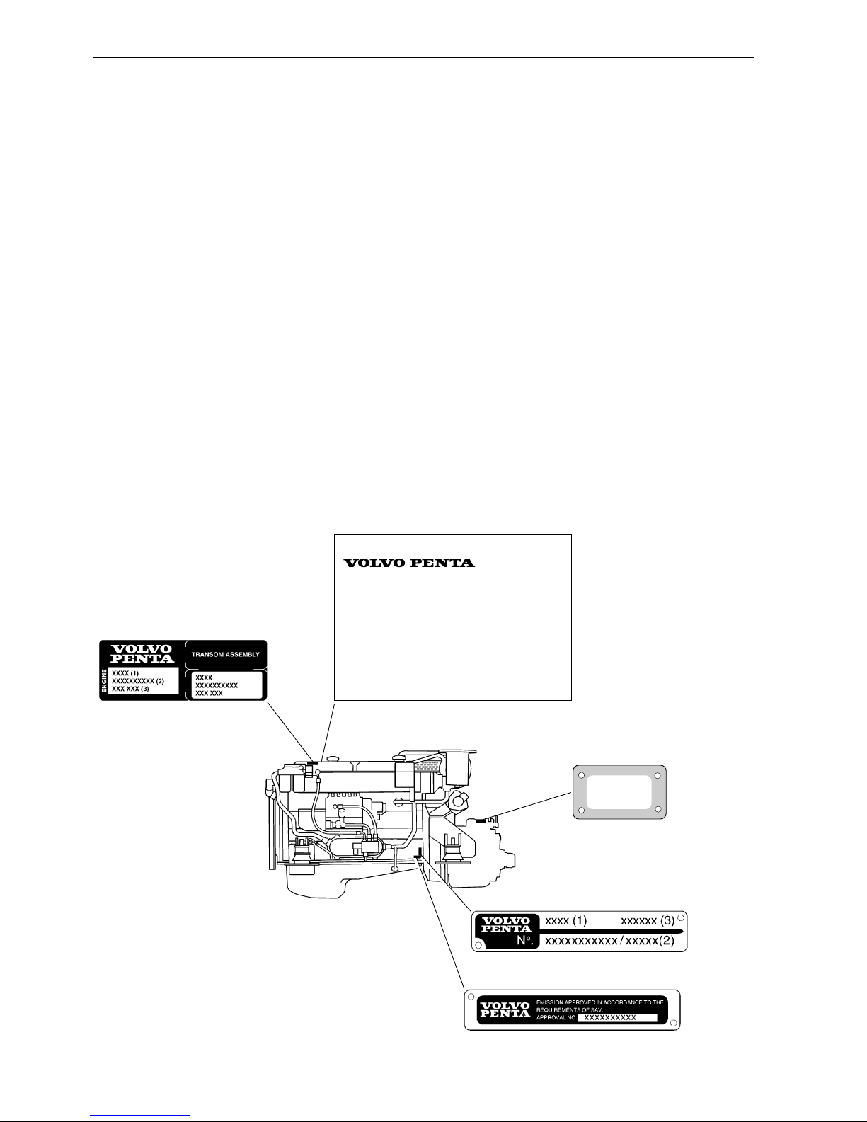
Type plates with identification number can be found on the engine and transmission. This information must always be used as a reference when ordering service and spare parts. Similar plates can probably be found on
your boat and its equipment. Make a note of the information in the space below and make a copy of this page so
the information is available even if the boat should be stolen.
The appearance and location of the type plates is shown below. The numbers in brackets refer to the location of
the identification number on the type plate.
Engine
Product designation (1) ......................................................................................................
Serial and basic engine number (2) ....................................................................................
Product number (3).............................................................................................................
Certification, IMO
Decal, part No. (4) ...............................................................................................................
Approval No. (5) ..................................................................................................................
Transmission
Product designation (6) .......................................................................................................
Serial number (7).................................................................................................................
Product number (8)..............................................................................................................
Engine and transmission decal
Reverse gear plate
Certification decal
Engine plate
Certification plate
(6)
(7)
(8)
XXXX (6)
XXXXXXXXXX (7)
IMPORTANT ENGINE INFORMATION
AB Volvo Penta, Sweden VP xxxx
(4)
IMO
ENGINE FAMILY xxxx ENGINE MODEL xxxx (1)
TEST CYCLES xxxx POWER (kW/RPM) xxxx
IMO APP NO. MTC xxxx
(5)
IMO APP NO. EP A –
ENGINE SERIAL NO. AVAILABLE ON ENGINE IDENTIFICATION PLATE
CERTIFICATE AND TECHNICAL FILE: AVAILABLE ON WWW.PENTA.VOLVO.SE
THIS ENGINE IS CERTIFIED BY SWEDISH ACCREDITED ORGANISATION MTC
IN ACCORDANCE WITH IMO NOX TECHNICAL CODE ANNEX VI MARPOL 73/78
Page 13
11
Presentation
TAMD63L, TAMD63P and TAMD74A are in-line,
direct injection, 6-cylinder, 4-stroke marine diesel
engines. They are equipped with turbocharger and fitted with either a heat exchanger for thermostatregulated freshwater cooling or connections for keel
cooling.
The engines are equipped with a seawater cooled
charge air cooler. The charge air cooler lowers the
temperature of the inlet air to the engine after it has
been compressed in the turbocharger. This allows
high power output while keeping combustion and
exhaust temperatures at a suitable level.
The exhaust manifold and turbocharger are freshwater cooled to reduce heat radiation to the engine
room.
These engines are equipped with mechanical fuel
control.
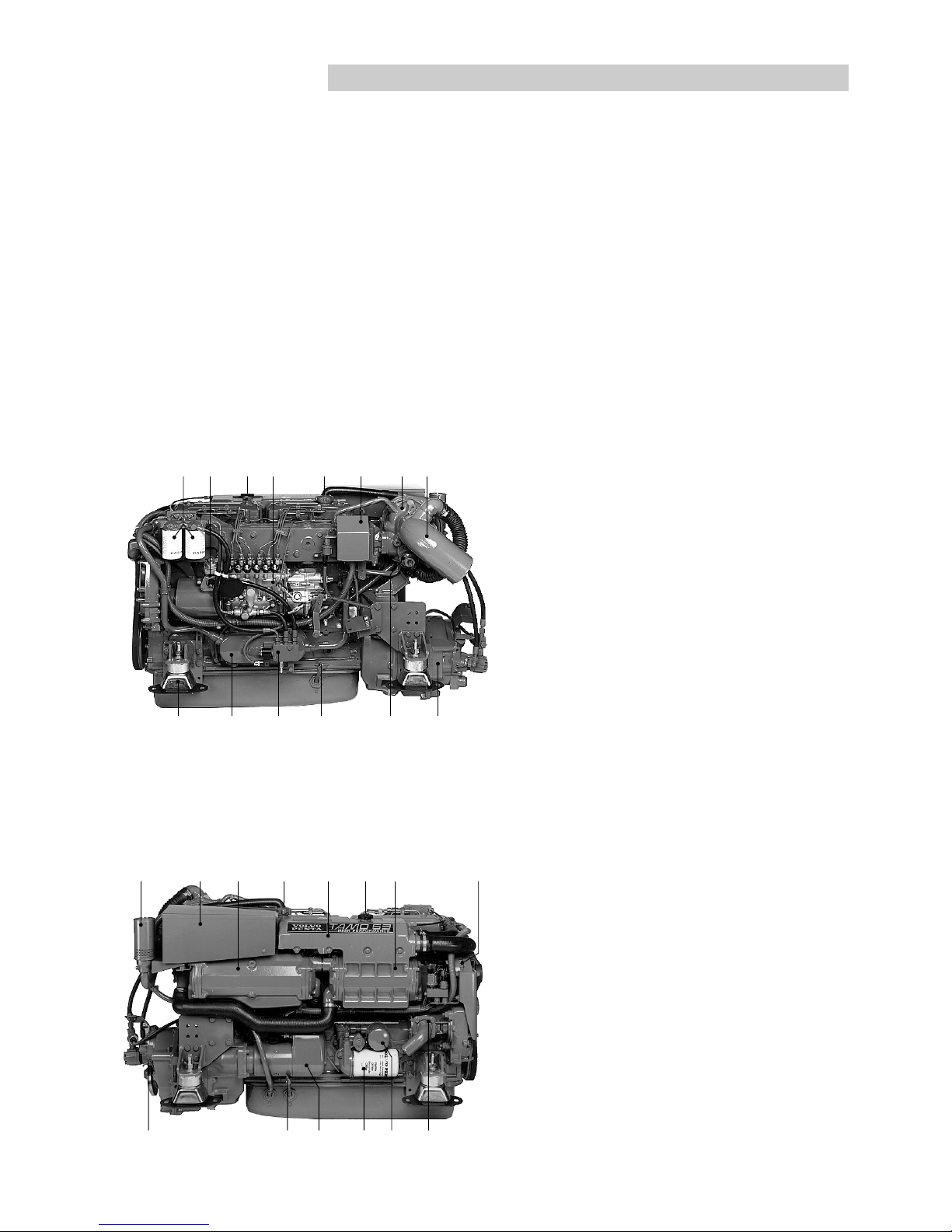
TAMD63L-A, TAMD63L-B, TAMD63P-A
1. Fuel fine filters
2. Smoke limiter
3. Coolant filler cap
4. Injection pump
5. Oil filler cap
6. Distribution box with semi-automatic
fuses
7. Turbocharger
8. Water cooled exhaust pipe elbow
(option)
9. Reverse gear (ZF (MPM) IRM 220A-1)
10. Wastegate valve (TAMD63P)
11. Oil dipstick, engine
12. Fuel shut-off valve
13. Oil cooler, engine
14. Flexible engine mounting (option)
TAMD63L-A, TAMD63L-B, TAMD63P-A
1. Filter for crankcase ventilation
2. Air filter
3. Charge air cooler
4. Oil filler cap
5. Expansion tank
6. Coolant filler cap
7. Heat exchanger
8. Alternator
9. Sea water pump
10. By-pass filter for engine oil
11. Oil filter, engine
12. Starter motor
13. Oil dipstick, engine
14. Oil dipstick, reverse gear
14 13 12 11 10 9
1234567 8
12 34 5 6 78
14 13 12 11 10 9
Page 14
12
Presentation
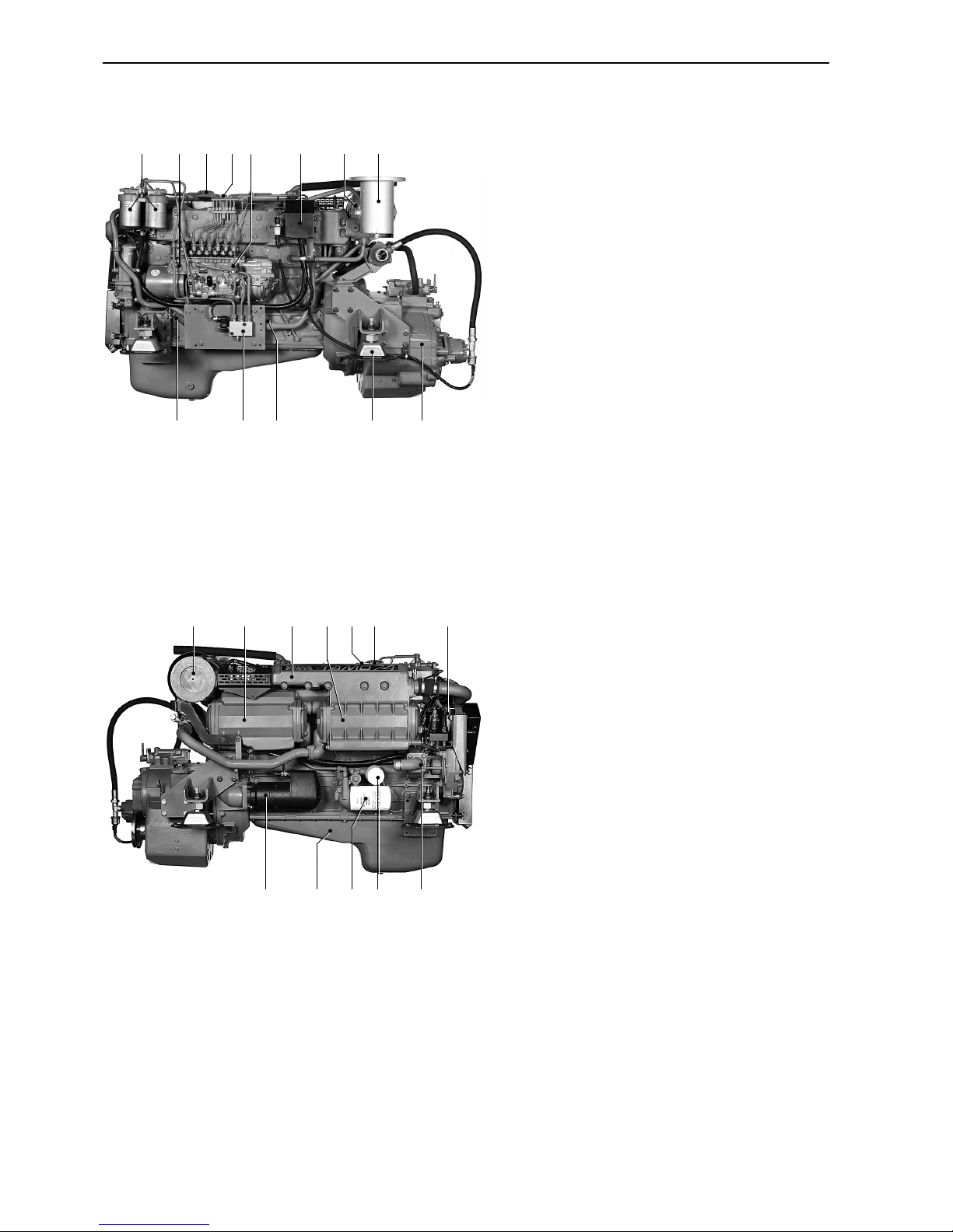
TAMD74A-A, TAMD74A-B
1. Fuel fine filters
2. Smoke limiter
3. Oil filler cap
4. Coolant filler cap
5. Injection pump
6. Distribution box with semi-automatic
fuses
7. Turbocharger*
8. Exhaust pipe elbow
9. Oil dipstick, engine
10. Fuel shut-off valve
11. Oil cooler, engine
12. Flexible engine mounting (option)
13. Reverse gear (TD MG5091DC)
* TAMD74A-B: With wastegate.
TAMD74A-A, TAMD74A-B
1. Air filter
2. Charge air cooler
3. Expansion tank
4. Heat exchanger
5. Coolant filler cap
6. Oil filler cap
7. Alternator
8. Starter motor
9. Oil sump
10. Oil filter, engine
11. By-pass filter for engine oil
12. Sea water pump
123456 7
8 9 10 11 12
12345 6 78
91011 1213
Page 15
13
Instruments
This chapter describes the Volvo Penta instruments that are available for your engine. Note that that tachometer,
oil gauge, temperature gauge, charge gauge, starting switch, etc., that are shown here as panel mounted may be
mounted separately in some boats.
If your boat is fitted with instruments not described here and you are not sure of their function, please get in touch
with your boat dealer.
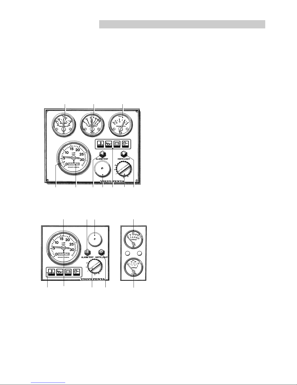
Instrument panels
Instrumentation for the main control position and auxiliary control position.
1. Temperature gauge. Indicates the engine coolant
temperature.
2. Oil pressure gauge. Indicates the pressure of the
engine lubricant.
3. Voltmeter. Indicates the charge voltage from the
alternator when the engine is running and the battery voltage when the engine is stopped.
4. Tachometer. Indicates the speed of the engine in
rpm.
5. Hour counter. Shows the total number of engine
running hours as a decimal number.
6. Press button for testing and acknowledging
alarms (see next page “Warning displays”).
7. Siren for acoustic alarm that sounds if one of the
warning lamps comes on.
8. Warning display (see next page “Warning displays”, pos 1–4).
9. Starting switch (see next page).
10. Press button for instrument illumination.
11. Oil pressure gauge. Indicates the oil pressure in
the reverse gear.
12. Charge air pressure gauge. Indicates the turbocharger boost pressure.
123
45678910
85 910
467
11
12
Page 16

14
Instruments
Control panels
Control panels for the main control position and auxiliary control position.
1. Siren for acoustic alarm that sounds if one of the
warning lamps comes on.
2. Press button for instrument illumination.
3. Press button for testing and acknowledging
alarms (see “Warning displays” below).
4. Starting switch.
5. Start button.
6. Stop button.
Warning displays
If the acoustic alarm sounds, one of the warning display lamps will immediately start to flash to indicate
the cause of the alarm.
1. Coolant temperature too high.
2. Lubricant pressure too low.
3. Alternator not charging
4. Not used
5. Lubricant level too low* (accessory).
6. Coolant level too low* (accessory).
7. Water in fuel pre-filter (accessory).
8. Auxiliary (accessory).
* Warns for low level with stationary engine and starter key in position I
(“Drive position”). Refill to correct level before starting the engine.
After an alarm
Press the “Alarm test” button to acknowledge and
terminate the acoustic alarm. The relevant warning
lamp will continue to flash until the fault has been
rectified.
Alarm test
After pressing the “Alarm test” button, the warning
lamps will come on and the acoustic alarm will start to
sound. Make a habit of always performing an alarm
test before starting.
1
2
4
3
5
678
5 6
2
3
1
12
3
4
Page 17
15
Instruments
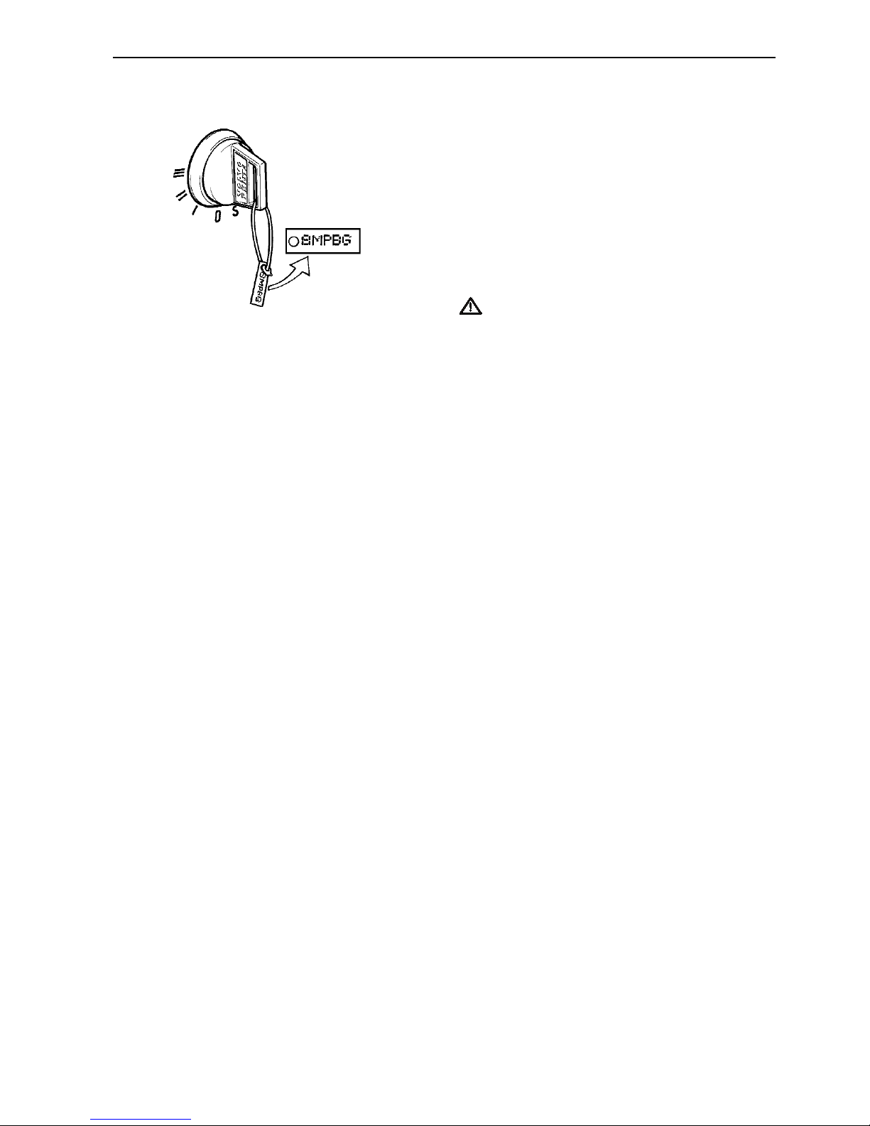
Starting switch
Delivered with the starter keys is a plate containing
the key code required when ordering additional starter keys. Do not keep the code where unauthorized
persons can access it.
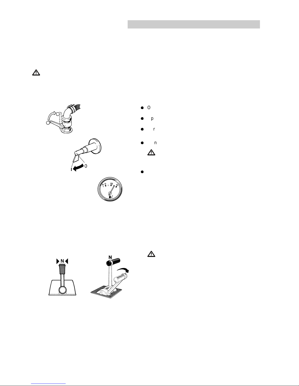
S = Stop position.
0 = Key can be inserted and removed.
I = Voltage on (drive position).
II = Not used
III = Start position.
IMPORTANT! Read the starting instructions in
the chapter “Starting the engine”.
Page 18
16
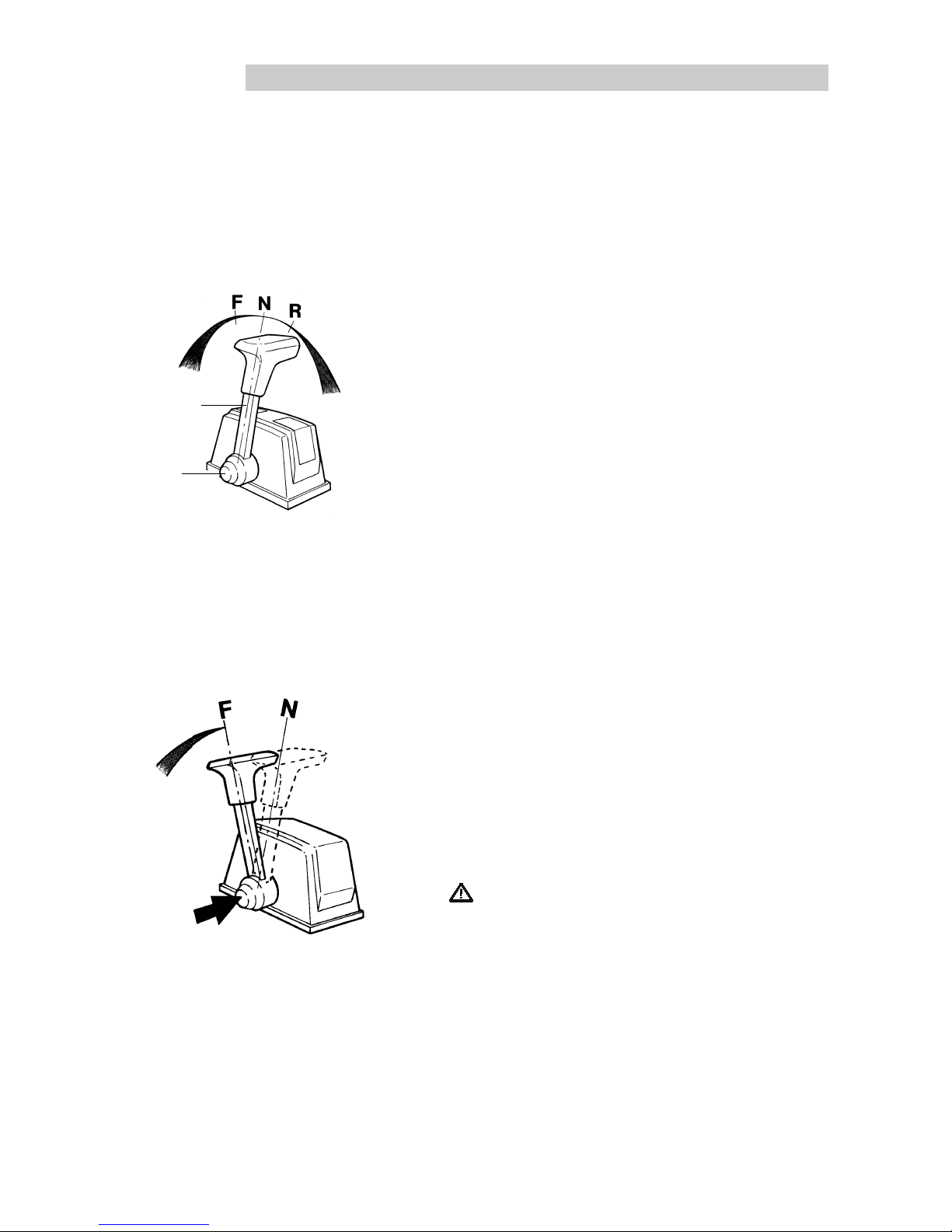
Single lever control
Manoeuvring
Single lever control operates shifting and engine speed
from the same lever (1).
N = Neutral position (reverse disengaged and engine
idling).
F = Reverse gear engaged for moving forwards.
R = Reverse gear engaged for moving backward.
= Engine speed control.
A neutral position switch is available as an accessory that
allows the engine to be started only when the reverse gear
is disengaged.
Controls
This chapter describes the Volvo Penta controls that are available for your engine. If your boat is fitted with controls not described here and you are not sure of their function, please get in touch with your boat dealer.
Disengaging the shifting function
The shifting function can easily be disengaged to that the
lever only affects the engine speed.
1. Put the lever (1) in neutral position (N).
2. Press the button (2) while moving the lever forward.
3. Release the button. The lever now affects the engine
speed only.
The disengagement will cease automatically when the lever is moved back to neutral position.
IMPORTANT! Take care not to engage the reverse
gear unintentionally.
T
T
2
1
Page 19
17
Controls
Friction brake
The control is fitted with an adjustable friction brake for
engine speed control.
1. Remove the cover on the control.
2. Set the lever to half acceleration/reverse.
3. Adjust the friction brake. Turn clockwise for stiffer lever
movement and anticlockwise for lighter movement.
4. Refit the cover.
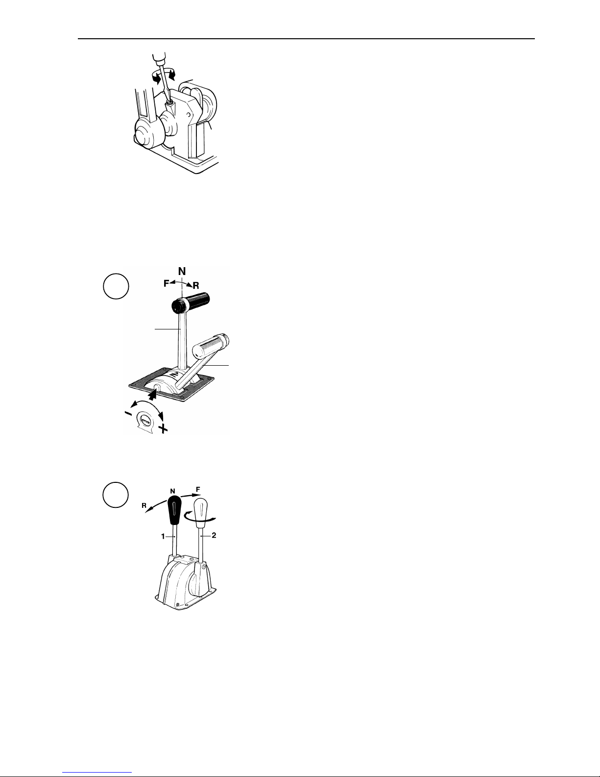
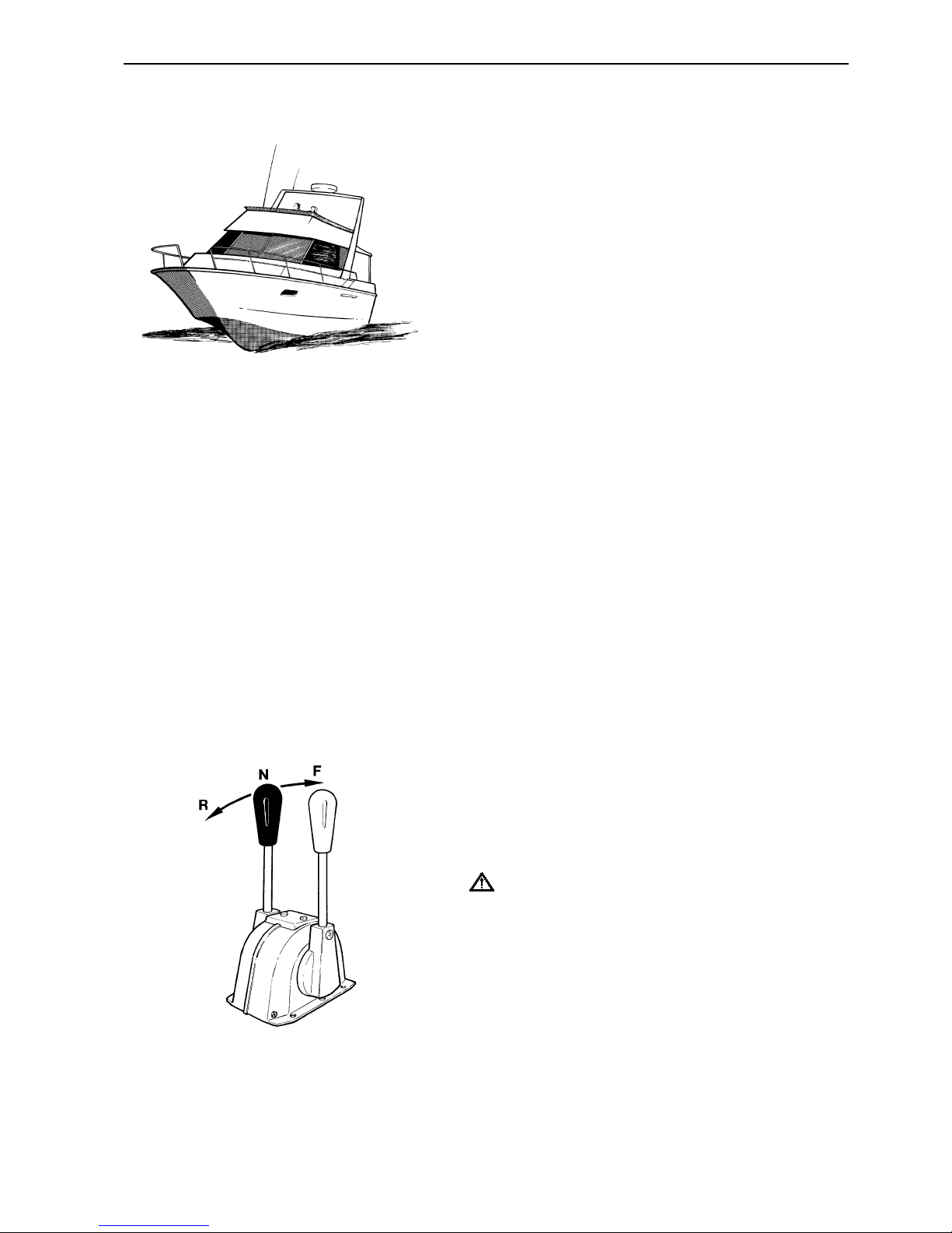
Dual lever control
Manoeuvring
The dual lever control has separate levers for shifting (1)
and engine speed control (2).
Control A has a mechanic detent so that shifting can be
performed only when the engine speed lever is in idle
speed position. A neutral position switch is available that
allows the engine to be started only when the reverse gear
is disengaged.
Black lever (1):
N = Neutral position. Reverse gear disengaged.
F = Reverse gear engaged for moving forwards.
R = Reverse gear engaged for moving backward.
Red lever (2):
Engine speed control.
Friction brake
The controls are fitted with an adjustable friction brake for
engine speed control.
Adjust the friction brake by turning the screw (control A) or
the lever (control B).
Turn clockwise (+) for stiffer lever movement and
anticlockwise (–) for lighter movement.
B
A
2
1
Page 20
18
Starting the engine
Make a habit of “visually” inspecting the engine and engine room before starting This will help you to quickly detect abnormalities that have occurred or are about to occur. Make sure instruments and warning displays indicate
normal values after starting the engine.
We recommend installing a heater for the engine room to minimize start smoke when cold starting at temperatures below +5oC (41oF).
WARNING! Never use start spray or similar start help. Risk for explosion!
Measures before start
l
Open the fuel cock
l
Open the seawater cock where appropriate
l
Carry out the measures described in “Daily before first
start” in the maintenance schedule.
l
Turn on the main switch
IMPORTANT! Never turn the power off using the
main switch while the engine is running. This can
damage the alternator.
l
Make sure there is enough fuel for the planned trip.
Starting procedure
1. Disengage the reverse gear
Put the control lever into neutral and idle on all control
positions
WARNING! If the boat is equipped with controls
that allow starting the engine in gear, it is essential
to check all control positions to make sure a gear
is not engaged.
Single lever control
Make sure the lever is in neutral position “N”. This
means the accelerator is in idle position and the reverse gear is disengaged.
Dual lever control
Put the forward/reverse lever in neutral position to enable starting. Move the accelerator all the way back
(idle position).
Page 21
19
Starting the engine
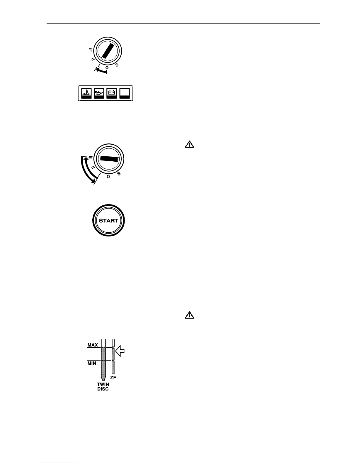
2. Turn on the power
Turn on the power by putting the starter key in position
“I”.
3. Check warning lamps and alarms
Press the “Alarm test” button on the instrument panel
to make sure the warning lamps come on and the
acoustic alarm sounds.
4. Start the engine
Start using the starting switch
Turn the key to position “III”. Release the key so it returns to “I” immediately after the engine has started.
IMPORTANT! If the starter motor has been engaged for the maximum time (30 seconds), it must
be allowed to cool down for at least one minute
before a new attempt is made at starting.
NOTE! The key must first be turned to “S” before making a new attempt at starting.
Start using the start button
Press the start button. Release the button immediately
after the engine has started (note that when starting
from the alternative control position, the starter key at
the main control position must be turned to “I”).
Start using auxiliary batteries
Refer to the description in the chapter “Troubleshooting”.
5. Check the instruments and run the engine
warm
Let the engine idle for the first ten seconds and make
sure the instruments and warning display show normal
values. Then run the engine at low speed and low load
so it attains normal operating temperature before using
full power.
IMPORTANT! Do not race the engine when it is
cold.
6. Check the oil level in the reverse gear
The oil level should be checked once the reverse gear
has attained operating temperature (see the description
in the chapter “Maintenance” under the heading “Reverse gear”).
Page 22
20
Operation
Learn how to handle the engine, controls and other equipment in a safe and correct manner before casting off for
your maiden voyage.
WARNING! Avoid violent and rapid rudder movement and gear shifting. There is a risk of the passengers
falling down or falling overboard.
WARNING! A rotating propeller can cause serious injury. Make sure there is nobody in the water before engaging forward/reverse. Never run close to bathers or in places where you have reason to believe there are
people in the water.
Check the instruments
Check the instruments and warning display directly after
start and regularly during operation.
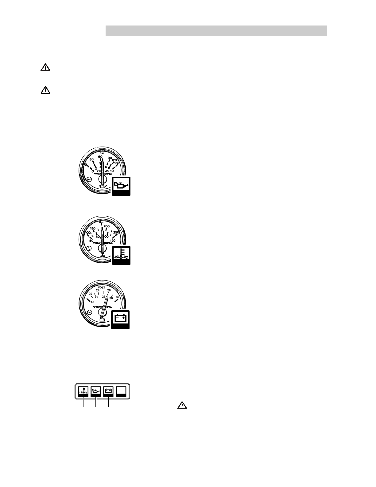
Oil pressure
During operation, the oil pressure gauge should show a
reading of 300–550 kPa (43.5–79.8 psi) or 450–650 kPa
(65.3–94 psi) for TAMD63 respectively TAMD74. A lower
value is normal at idling speed. The acoustic alarm will
sound automatically in case of low oil pressure.
Coolant temperature
During operation, the temperature gauge should show a
reading of 75–90°C (167–194°F). The acoustic alarm will
sound automatically in case the coolant temperature is too
high.
Charging
During operation, the charge voltage gauge should show a
reading of 14V or 28V for a 12 respectively 24V system.
The acoustic alarm will sound automatically in case the
charge voltage is missing.
Alarms and fault indication
If the acoustic alarm sounds, one of the warning display
lamps will immediately start to flash to indicate the cause
of the alarm: High coolant temperature (1), low oil pressure
(2) and no charge voltage (3).
IMPORTANT! Stop the engine immediately after an
alarm for low oil pressure. Investigate the cause and
rectify it.
Slow the engine speed to idle/disengaged after an alarm
for high coolant temperature. If temperature does not drop,
the engine must be stopped. Investigate the cause and
rectify it.
123
Page 23
21
Operation
Cruising speed
Avoid running at full speed to obtain the best operating
economy. We recommend a cruising speed of at least
200 rpm lower than the maximum rpm at full speed (wide
open throttle). The maximum rpm at full speed can vary
depending on choice of propeller, load and sea conditions,
etc., but should be within the wide open throttle range.
Wide open throttle range:
TAMD63L-A/L-B (Rating 2) ..................... 2400–2500 rpm
TAMD63L-A/L-B (Rating 3) ..................... 2700–2800 rpm
TAMD63P-A (Rating 4, 5)........................ 2700–2800 rpm
TAMD74A-A (Rating 1, 154 kW*) ............ 1700–1800 rpm
TAMD74A-A (Rating 1, 160 kW*) ............ 1900–2000 rpm
TAMD74A-A (Rating 1, 184 kW*) ............ 2000–2100 rpm
TAMD74A-A (Rating 2)............................ 2100–2200 rpm
TAMD74A-B (Rating 2)............................ 2100–2200 rpm
* Max. motor effect.
There could be several reasons for the engine failing to
reach the wide open throttle range, see the chapter “Troubleshooting”. Use a propeller with a greater pitch if the engine speed exceeds the wide open throttle range. Get in
touch with your Volvo Penta dealer for advice.
Manoeuvring
The chapter contains functional descriptions of the controls
available from Volvo Penta.
The reverse gear must be engaged at low idling speed.
There must be a brief pause after engaging reverse gear
before increasing the engine speed. The pause must be
approximately two seconds long to ensure the reverse
gear clutch plates are properly engaged.
IMPORTANT! If the boat is equipped with two engines, they must both be running while in reverse or
there will be a risk of water entering the stationary engine (through the exhaust passage).
Pulling away
1. Move the lever from neutral to the engagement position
for the desired direction of travel. Wait for approximately two seconds.
2. Increase gradually to the desired engine speed.
Page 24

22
Operation
Forward–Reverse
1. Slow the engine speed to idling and allow the boat to
loose most of its speed.
2. Move the lever to neutral. Wait for approximately two
seconds.
3. Move the lever to reverse. Wait for approximately two
seconds and then increase the engine speed gradually.
IMPORTANT! A direct forward–reverse manoeuvre
can damage the transmission and engine. It is therefore always necessary to stop with the lever in neutral
for a few seconds. Allow the boat to loose most of its
speed as well before engaging. If the speed of the
boat is too high, there is a risk of the propeller torque
being so high that the engine will stop and start reversing, causing the engine to break down.
Forced propeller rotation
(E.g. when towing)
When towing, sailing, anchoring in strong currents, etc.,
the propeller can make the propeller shaft rotate even
though the engine is stationary. This rotation may be uncomfortable and can damage the reverse gear.
IMPORTANT! The propeller shaft can be allowed to
rotate with a stationary engine for up to 6–8 hours.
After that period, the engine must be started and run
for at least 5 minutes to enable lubrication and cooling
of the reverse gear.
In cases where the propeller shaft may rotate faster than
during normal operation, e.g. when sailing, a temperature
gauge should be fitted to monitor the oil temperature. Max.
permitted temperature is 110°C (230°F) for Twin Disc and
95°C (203°F) for ZF (MPM) reverse gear.
A shaft brake must be fitted if the above directions cannot
be followed or if it is necessary to stop the shaft for reasons of comfort. On isolated occasions, the propeller shaft
flange can be locked mechanically in a suitable manner.
Page 25

23
Operation
Accessories
Trolling valve
Certain Twin Disc reverse gears can be fitted with a trolling
valve so that the lowest speed of the boat can be variably
reduced by 1–80% at engine speeds up to 1100 rpm.
IMPORTANT! Risk of overheating the reverse gear if
the trolling valve is used at higher engine speeds than
1100 rpm.
Manoeuvring
Disengage the reverse gear and set the trolling valve for
maximum slip. Engage “Forward” or “Reverse” and set the
desired slip position within the permitted engine speed
range.
In order to attain full propeller output, the trolling valve
lever must always be in “disengaged” position when not
being used.
Flush and bilge pump
The bilge pump has a vacuum switch (1) that automatically
disengages the pump when water is no longer being drawn
into the pump.
The scavenging and bilge pump is engaged and disengaged from a switch that is normally located at the main
control position. The bilge pump can also be engaged
manually by holding down the lever 2 for about 20 seconds.
Page 26

24
Stopping the engine
Let the engine run at low idling speed (in neutral) for at least three minutes before turning it off. This will keep the
engine temperature in balance and prevent it boiling.
IMPORTANT! The procedure described above is especially important if the engine has been run hard and/
or exerted to heavy loads.
Stop
1. Disengage the reverse gear by moving the lever to neutral position.
2. Turn the key to stop position “S” or press the stop button.
3. Hold the key/button in position until the engine has
stopped (the key will return to “0” automatically when
released and can then be removed).
Emergency stop
If a fault occurs that prevents the engine being stopped by
the normal method, it can be stopped manually using the
lever on the injection pump. Pull back on the lever until the
engine is stationary.
WARNING! Working on or approaching a running en-
gine is a safety hazard. Beware of rotating parts and
hot surfaces.
After stopping
l
Check the engine and engine room for leaks.
l
Close the fuel cock and seawater cock.
IMPORTANT! Do not forget to open the cocks
before starting the engine again.
l
Read off the hour counter and carry out preventive
maintenance according to the maintenance schedule.
l
Turn off the main switch if the engine is not to be used
for long periods.
IMPORTANT! Never turn the power off using the
main switch while the engine is running. This can
damage the alternator.
Page 27

25
Stopping the engine
Anti-freezing measures
If the engine room cannot be protected from frost, the seawater system must be drained and the coolant in the freshwater system must contain sufficient anti-freeze to prevent
it from freezing. Refer to chapter Maintenance “Seawater
system” and “Freshwater system” respectively.
WARNING! If the seawater system bursts due to
freezing, it is possible for the boat to sink.
IMPORTANT! If the coolant does not give sufficient
anti-freeze protection, it may cause costly damage to
the engine.
Check the charge of the battery. A poorly charged
battery can freeze and break.
Breaks in operation
During breaks in operation when the boat is in the water,
the engine must be run warm once a fortnight. This will
prevent the engine from corroding.
IMPORTANT! The engine must be conserved if it is
not to be used for longer than two months: Refer to:
Inhibiting
Page 28

26
Maintenance schedule
Your Volvo Penta engine and associated equipment is designed to provide high operational reliability and long
service life. They are constructed to withstand the marine environment while also affecting it as little as possible.
Preventive maintenance in accordance with the maintenance schedule will ensure that it retains these qualities
and avoid unnecessary operational disturbances.
Warranty inspection
The prescribed warranty inspection “First Service Inspection” must be carried out at an authorised Volvo Penta
workshop during this first period of operation. Directions for when and where this is to be carried out can be
found in the Warranty and Service Book.
MAINTENANCE SCHEDULE
WARNING! Read the chapter “Maintenance” thoroughly before starting any mainte-
nance work. It contains directions for performing maintenance in a safe and correct
manner.
IMPORTANT! When both operating time and calendar time is given, the one occurring first is to apply. Maintenance points marked with are to be carried out at an
authorised Volvo Penta workshop.
Daily before first start
l
Engine and engine room. General inspection ............................................... page 29
l
Engine oil. Check level ................................................................................. page 33
l
Coolant. Check level..................................................................................... page 37
l
Charge air cooler. Check the drain hole ....................................................... page 46
l
Reverse gear. Checking oil level (after start)................................................ page 58
After the first 10 operating hours
l
Reverse gear (ZF/MPM). Clean oil strainer.................................................. page 58
After the first 50 operating hours
l
Reverse gear (Twin Disc and ZF/MPM). Clean oil strainer .......................... page 58
l
Reverse gear (Twin Disc and ZF/MPM). Changing oil ................................. page 59
Every 50 operating hours / at least every 12 months
l
Fuel pre-filter. Check and drain .................................................................... page 50
Page 29

27
Maintenance schedule
Every 25–200 operating hours1) / at least every 12 months
l
Engine oil. Change 1).................................................................................... page 33
l
Oil filter. Change 2)........................................................................................ page 34
1)
The oil change interval varies depending on the engine type, oil grade and sulphur content of
the fuel. See page 32.
2)
The oil filter is changed in every second oil change.
After the first 100 operating hours
Valve clearances. Check ...................................................................... not illustrated
Every 250 operating hours / at least every 12 months
l
Crankcase ventilation(TAMD63). Change filter............................................. page 30
l
Drive belts (not Poly-V). Check / Adjustment................................................ page 30
l
Air filter (TAMD63). Clean ............................................................................ page 31
l
Seawater filter. Check/clean ......................................................................... page 45
l
Zinc anodes. Check/Change ........................................................................ page 45
l
Fuel pre-filter(Double filter). Check1)............................................................. page 49
l
Electrical connections. Check/clean ............................................................. page 52
l
Reverse gear (ZF/MPM). Clean oil strainer.................................................. page 58
1)
Concerns only double filters: Check the manometer and change filter if necessary, but change
filter at least every 1000 operating hours or at least once at year.
Every 500 operating hours / at least every 12 months
l
Drive belts(Poly V). Check / Adjustment....................................................... page 30
l
Coolant (Anti-corrosion mixture). Topping up1)............................................. page 36
l
Battery. Ceck of electrolyte........................................................................... page 53
l
Reverse gear (ZF/MPM). Changing oil......................................................... page 59
1)
This applies only if the cooling system is filled with an anti-corrosion mixture.
Every 1000 operating hours / at least every 12 months
Valve clearances. Check/Adjust ...........................................................not illustrated
l
Air filter (TAMD74). Change ......................................................................... page 31
l
Fuel filter. Change ........................................................................................ page 48
l
Fuel pre-filter. Change filter element............................................................. page 50
l
Reverse gear (Twin Disc). Clean oil strainer ................................................ page 58
l
Reverse gear (Twin Disc). Changing oil ....................................................... page 59
Page 30

28
Maintenance schedule
Every 2000 operating hours
Injectors. Pressure test.........................................................................not illustrated
Every 12 months
Turbocharger. Check............................................................................not illustrated
Wastegate (TAMD63P, TAMD74A-B). Check ...................................... not illustrated
Engine and reverse gear. General check .............................................not illustrated
Heat exchanger. Check / Clean............................................................not illustrated
Charge air cooler. Check / Clean..........................................................not illustrated
Oil cooler (Reverse gear). Check / Clean .............................................not illustrated
l
Impeller (Seawater pump). Check / Change................................................. page 44
l
Impeller (Flush pump/Bilge pump). Check / Change ............................ not illustrated
l
Engine and reverse gear. Clean / Paint ................................................not illustrated
Every 24 months
l
Coolant. Change........................................................................................... page 37
l
Cooling system. Flushing ............................................................................. page 39
Renovated engine:
After the first 100 operating hours
Valve clearances. Check ...................................................................... not illustrated
Page 31

29
Maintenance
This chapter contains general technical information and directions for carrying out the prescribed maintenance
points. Read the directions carefully before starting work. The times at which the maintenance points are to be
carried out can be found in the previous chapter “Maintenance schedule”.
WARNING! Read the safety directions for maintenance and service in the chapter “Safety information” before starting work.
WARNING! Maintenance and service must be carried out on a stationary engine unless specified otherwise. Stop the engine before opening or dismantling the engine hatch/hood. Prevent inadvertent start of the
engine by removing the starter key and turning off the power with the main switch.
Engine, general
General inspection
Make a habit of “visually” inspecting the engine and
engine room before starting the engine and after
stopping when the engine has been turned off. This
will help you to quickly detect abnormalities that have
occurred or are about to occur.
Look especially carefully for oil, fuel and coolant
leaks, loose bolts, worn or slack drive belts, loose
connections, damaged hoses and electric cables.
This inspection takes only a few minutes but can prevent serious operating disturbances and costly repairs.
WARNING! Accumulations of fuel, oil and
grease on the engine or in the engine room is a
fire hazard and must be removed immediately
they are detected.
IMPORTANT! If an oil, fuel or coolant leak is detected, the cause must be investigated and the
fault rectified before the engine is started.
IMPORTANT! Never point high-pressure water
jets directly at seals, rubber hoses or electrical
components. Never use the high-pressure function when washing the engine.
Page 32

30
Maintenance: Engine, general
Crankcase ventilation. Change filter
(TAMD63)
Change the filter (1) earlier than recommended if oil is
forced out of the relief valve (2).
1. Dismantle the filter (1) by screwing it anti-clockwise.
2. Check the rubber gasket in the bracket and
change if necessary. Screw on the new filter by
hand.
Drive belts. Check/Adjust/Change
WARNING! Stop the engine before commenc-
ing maintenance work.
General
Check belt tension and condition regularly. If the belt
is too taut it can damage bearings and if it is too loose
it may slip. Check and adjust after operation when the
belt is warm.
IMPORTANT! Always change a belt that appears worn or is cracked (belts working in pairs
must be replaced together).
Poly-V belt
The alternator and circulation pump are driven by a
Poly-V belt for best function and service life.
A torque wrench must be used for adjustment.
1. Undo screws (A) before you tension the belt.
2. Change the belt as necessary.
3. Put the torque wrench stub into the square hole in
the jockey wheel bracket. Tension the belt with 60
±3 Nm (6 ±0.3 kpm/44 ±2 lbf.ft).
4. Tighten screws (A).
Other belts
Also check the belts for the bilge and flushing pump,
extra alternator etc. These are usually driven by conventional V- belts.
Adjust and change as necessary. It can generally be
said that these belts are correctly tensioned if they
can be pressed down 10 mm (3/8") by thumb pressure.
Clean the belt grooves before fitting a new belt.
Page 33

31
Maintenance: Engine, general
Air filter. Cleaning (TAMD63)
1. Remove the lid from the air filter housing.
2. Remove the insert and wash it in clean diesel oil.
3. Squeeze the insert out and put it back in the filter
housing. Fix the insert by pressing the O-ring into
the groove around the outside edge of the insert.
IMPORTANT! Change the insert if it is damaged.
Air filter. Changing (TAMD74)
1. Remove the old filter. Be careful to ensure that no
contamination gets into the engine.
2. Install a new filter and tighten the hose clamps.
IMPORTANT! Scrap the old filter. It must not be
cleaned.
Page 34

32
Maintenance: Lubricating system
SAE5W/30
−−
−−
−30
−−
−−
−20
−−
−−
−10 ±0 +10 20 30 40
−−
−−
−22
−−
−−
−4
++
++
+14 32 50 68 86 104
−−
−−
−15
o
C
SAE15W/40
−−
−−
−25
o
C
SAE10W/30
−−
−−
−10
o
C
SAE20W/30
±0oC
SAE30
SAE40
+10oC
o
C
o
F
✱✱
✱✱
✱
Lubricating system
Oil change intervals can vary from 25 to 200 hours depending on engine type, grade of lubricant and the sulphur
content in the fuel.
IMPORTANT! Oil change intervals must never exceed 12 months.
If you would like longer oil change intervals than those specified in the table below, samples of the lubricant must
be sent regularly to the oil manufacturer for checking.
Viscosity
Select the viscosity from the table for constant
exterior temperatures.
*Refers to synthetic or semi-synthetic oil
Oil change volume
See “Technical data”
NOTE! Mineral based synthetic or semi-synthetic oil can be used on condition that it meets the oil grades
above.
1)
If the sulphur content in the fuel exceeds 1.0 wt.%, an oil with TBN14–20 must be used (TBN=Total Base Number)
2)
The oil must be changed at least once a year
VDS = Volvo Drain Specification
ACEA = Association des Constructeurs Européenne d'Automobiles
API = American Petroleum Institute
Oil grade Fuel sulphur content in wt.%
up to 0.5 % 0.5 – 1.0 % above 1.0 %
1)
Oil change interval
2)
VDS, VDS-2 200 hours 100 hours 50 hours
100 hours 50 hours 25 hours
ACEA E3–96, E2–96
API CD, CE, CF, CF–4, CG–4
Page 35

33
Maintenance: Lubricating system
Engine oil. Check level
The oil level must be within the marked range on the
dipstick and must be checked daily before starting the
first time.
Engine oil. Change
Always observe the recommended oil change interval. Use a manual or electric oil scavenging
pump (optional equipment) to suck the oil out of
the sump.
IMPORTANT! Only use recommended grades
of oil (see previous page).
1. Warm the engine up (this makes it easier to suck
the oil up from the sump). Then stop the engine.
WARNING! Hot oil and hot surfaces can
cause burns.
2. TAMD63 (electric oil scavenging pump):
Remove the dipstick. Connect the suction hose of
the oil scavenging pump to the dipstick tube (1).
Suck the oil out.
TAMD74 (manual oil scavenging pump):
Connect a hose to the outlet pipe of the oil scavenging pump. Suck the oil out.
3. Change the oil filter and the by-pass filter at every
second oil change (please refer to the instruction
on the next page).
4. Fill up with oil to the correct level.
Engine oil. Filling
Top up the oil through the filler opening (1) in the ventilation cover. Make sure the correct level is attained
but wait a few minutes to allow the oil to run into the
oil sump.
IMPORTANT! Do not fill above the maximum oil
level. Use only oil of the recommended grade
(see the previous page).
1
1
TAMD63
TAMD74
Page 36

34
Maintenance: Lubricating system
5. Start the engine and allow it to idle. Check that the
low oil pressure warning lamp goes out and that
there is no leakage by the filter.
WARNING! Approaching or working with a
running engine is a safety risk. Be careful to
avoid rotating components and hot surfaces.
6. Stop the engine. Wait a few minutes before you
check the oil level. Top up as necessary.
NOTE! Process the old oil filter in accordance with local regulations.
Oil filter and by-pass filter. Changing
Change the oil filter and by-pass filter every second
oil change. Standard filter location is on the right side,
but they can be located at the rear of the engine if
necessary (option).
WARNING! Hot oil and hot surfaces can cause
burns!
1. Drain the oil as in the “Engine oil changing” instruction on the previous page.
2. Put a vessel underneath the filter to avoid oil spillage. Unscrew the oil filter (1) and by-pass filter (2).
3. Check that the mating surfaces on the filter
bracket are clean, and that no traces of the seal
from the old oil filter remain.
4. Wipe some oil on the rubber seal for the new filter.
5. Screw the filters on by hand until the rubber seal
just touches the mating surface of the filter
bracket. Then turn it another half turn, and no
more!
6. Fill up with oil as in the “Engine oil, changing” instruction on the previous page.
1
2
Page 37

35
Maintenance: Freshwater system
Freshwater system
The freshwater system is the internal engine cooling system. It is a closed system and must always be filled with
a coolant that protects it against internal corrosion and freezing when the climate demands.
The circulation pump ensure good circulation in the system. The thermostat will start to open at a certain temperature and will be fully open when the engine has attained normal operating temperature. When the thermostat
opens, the warm coolant passes through the heat exchanger where it is cooled by the water in the engine’s seawater system.
In its standard version, the engine is fitted with an internal freshwater system. Volvo Penta also supply engines
with the cooling system prepared for external cooling, e.g. keel cooling.
Coolant. General
The freshwater system must always be filled with a
coolant that protects it against internal corrosion and
freezing when the climate demands.
Anti-corrosive additives become less efficient with
age and the coolant must therefore be changed.
IMPORTANT ! Never use only water as a cool-
ant and change the coolant in accordance with
the recommendations in the maintenance
schedule.
Water quality
To avoid clogging the system, the coolant must be
mixed with pure water in accordance with ASTM
D4985. If there are doubts about the purity of the water, use distilled water or ready-mixed coolant instead.
ASTM D4985:
Total solid particles ....................................... < 340 ppm
Total hardness................................................ < 9.5° dH
Chloride........................................................... < 40 ppm
Sulphate .......................................................... < 100 ppm
pH-value .......................................................... 5.5–9
Silicon ............................................................. < 20 mg SiO2/l
Iron................................................................... < 0.10 ppm
Manganese...................................................... < 0.05 ppm
Conductivity ................................................... < 500 µS/cm
Organic content, CODMn................................ < 15 mg KMnO4/l
Page 38

36
Maintenance: Freshwater system
Anti-freeze mixture
When there is risk of freezing, a mixture of 50% Volvo
Penta anti-freeze (glycol) and 50% water (complying
with ASTM D4985) must be used. This mixture will
protect against freezing down to approx. –40°C
(–40°F) and is to be used all year round.
IMPORTANT! Even if the temperature never
falls as low as –40°C (–40°F), the mixture specified above should still be used to provide adequate anti-corrosive properties.
Mix the glycol with water in a separate container before filling the cooling system.
WARNING! Glycol is a health hazard (poison!).
IMPORTANT! Alcohol must not be used in the
cooling system.
Anti-corrosion mixture
Water (complying to ASTM D4985) mixed with Volvo
Penta anti-corrosion agent can be used as a coolant
when there is no risk of freezing.
Using an anti-freeze mixture all year round is recommended, however, whatever the climate.
Mix as directed on the packaging. Run the engine
warm after filling to obtain the best effect of the additive.
If the operating time exceeds 500 hours a year, the
anti-corrosive protection in the coolant must be supplemented with 1/2 litre anti-corrosion agent every
500 hours.
WARNING! Anti-corrosion agent is a health hazard (poison!).
IMPORTANT! Never mix anti-corrosion agent
with anti-freeze (glycol). Frothing can occur and
severley impair the cooling properties.
Page 39

37
Maintenance: Freshwater system
Coolant level. Check
WARNING! Never open the pressure cap when
the engine is warm. Steam or hot fluid may spurt
out.
IMPORTANT! Check the coolant level on a cold
stationary engine.
Make sure the coolant level is approx. 5 cm (2")
below the sealing surface of the filling cap. Fill as necessary as described below.
Coolant. Filling
CAUTION! Stop the engine and allow it to cool
down before filling. Hot oil and hot surfaces can
cause burns.
Topping up
Fill with coolant to the correct level through the filler
opening on the expansion tank. Fill slowly so that the
evacuated air is able to pass through the filler opening.
IMPORTANT! Use the same type of coolant that
is already in the system.
IMPORTANT! If the heat exchanger is empty,
the coolant must be filled according to the description “Filling the cooling system when empty”.
Filling the system when empty
1. Open the ventilation cocks by the turbocharger
and the heat exchanger.
2. Make sure any other systems such as heater, wa-
ter heater, etc., connected to the cooling system
are also ventilated.
3. Fill with coolant through the filler opening on the
expansion tank.
4. Fill slowly so that the evacuated air is able to pass
through the ventilation cock/cocks and the filler
opening.
Page 40

38
Maintenance: Freshwater system
5. When coolant that is free from air flows out, the
ventilation cocks must be closed.
6. Cease filling when the correct level is attained.
7. Start the engine and run it until it reaches operating temperature.
IMPORTANT! The engine must not be started before the system has been bled and
filled.
8. Stop the engine and allow it to cool down. Check
the coolant level and top up if needed.
Coolant. Drain
WARNING! Stop the engine and allow it to cool
down before draining. Hot coolant and hot surfaces can cause burns.
WARNING! Glycol is a health hazard (poison).
Collect the old coolant and leave it to a destruction plant.
IMPORTANT!
The coolant is drained via the
taps (1–3) and the plugs (4, 5). Most of the coolant is drained via tap (1) but all drain points must
be opened for all coolant to be drained.
1. Remove the filler cap on the expansion tank.
2. Open vent cock (A) and vent cocks (B) by the
heat exchanger.
3. Connect a suitable hose to tap (1) on the cylinder
block. Open the tap and let the coolant run out into
a suitable vessel.
IMPORTANT! Check that the coolant really runs
out. Deposits may need to be removed inside the
drain plugs/taps.
4. Continue with the other drain points until all five
have been opened and all coolant has been
drained off.
5. Drain any other systems such as heater, water
heater, etc., connected to the freshwater system
too.
6. Close all drainage points.
1
2
4
A
5
3
B
Page 41

39
Maintenance: Freshwater system
Freshwater system. Flushing
The system should be flushed before changing coolant to avoid inferior cooling performance due to deposits in the cooling system.
IMPORTANT! Certain parts of the system are
made of light alloy. Chemical additives must
therefore not be used when cleaning.
1. Drain the coolant as described earlier.
2. Insert a hose into the filler opening on the expan-
sion tank and flush with fresh water.
3. Flush until the water running out of the drainage
points is clean.
4. Close all drainage points when all the fresh water
has run out.
5. Fill with coolant.
Page 42

40
Maintenance: Freshwater system
Cooling system, external cooling
Introduction
A cooling system with external cooling does not have a heat exchanger but is cooled by heat being transferred
via one or two external cooling circuits. A single circuit system serves all the components being cooled. A dual
circuit system has either two freshwater circuits or one freshwater circuit together with one seawater circuit. In
both cases, one of the circuits cools the engine and the other circuit cools the charge air cooler and the oil coolers.
Coolant level. Check
WARNING! Never open the filler cap when the
engine is warm. Steam or hot fluid may spurt
out.
Make sure the level ends up between the MIN and
MAX marks. If there are no marks, the coolant level
should be approx. 5 cm (2") below the sealing surface
of the filling cap (1). Fill if necessary with the same
type of coolant that is already in the system.
IMPORTANT! Check the coolant level on a cold
stationary engine.
1
Two circuits
Two circuits
One circuit
One or two
circuits
Page 43

41
Maintenance: Freshwater system
Coolant. Filling
WARNING! Stop the engine and allow it to cool
down before filling. Hot oil and hot surfaces can
cause burns.
Topping up
Fill with coolant to the correct level through the filler
opening (1) on the expansion tank. Fill slowly so that
the evacuated air is able to pass through the filler
opening.
IMPORTANT! Use the same type of coolant that
is already in the system.
IMPORTANT! If the heat exchanger is empty,
the coolant must be filled according to the description “Filling the cooling system when empty”.
Filling the system when empty
1. Open the vent tap by the turbocharger (2) and at
the keel cooler circuit return pipe (3).
NOTE! Do not open the bleed screw by the charge
air cooler if the circuit is part of the seawater system.
2. Make sure any other systems such as heater, wa-
ter heater, etc., connected to the cooling system
are also ventilated.
3. Fill with coolant via the filler opening on the expan-
sion tank.
4. Fill slowly so that the evacuated air is able to pass
through the ventilation cock/cocks and the filler
opening.
5. Close the ventilation cocks/cocks as coolant that
is free from air runs out of them.
6. Cease filling when the correct level is attained.
7. Start the engine and run it until it reaches operat-
ing temperature.
IMPORTANT! The engine must not be started before the system has been bled and
filled.
8. Stop the engine and allow it to cool down. Check
the coolant level and top up if needed.
3
2
Page 44

42
Maintenance: Freshwater system
Coolant. Drain
WARNING! Stop the engine and allow it to cool
down before draining. Hot oil and hot surfaces
can cause burns.
WARNING! Glycol is a health hazard (poison).
Collect the old coolant and leave it to a destruction plant.
1. Remove the filler cap.
2. Open the vent tap (2) by the turbocharger and at
the keel cooling circuit return hose union (3).
3. Open the cocks shown in “Coolant. Drain” (standard system). Open also the cocks shown in “Seawater system. Drain” on systems without seawater
circuit. Collect the fluid in a suitable receptacle.
IMPORTANT! Make sure the coolant really
runs out. It may be necessary to clean away
deposits inside the drain cocks.
4. Drain any other systems such as heater, water
heater, etc., connected to the freshwater system
too.
5. Close all cocks.
2
3
Page 45

43
Maintenance: Seawater system
Seawater system
The seawater system is the engine’s external cooling system. The seawater pump draws in water via the seawater intake and pump it on through the charge air cooler, heat exchanger and the reverse gear oil cooler. The
system is protected against galvanic corrosion by zinc anodes located in the charge air cooler, heat exchanger
and the reverse gear oil cooler.
WARNING! There is a risk that water will enter while working on the seawater system (if the boat is in the
water). Water may flow into the boat if a hose, plug or similar object located below the waterline. So always
close the seawater cock. If the boat does not have a seawater cock, the flow of water must be stopped in a
safe manner. The boat must be brought up on land if this is not possible.
Seawater system. Drain
The seawater system must be drained during cold
weather when there is a risk of freezing to prevent the
system from bursting.
An alternative to draining is to keep the engine room
free from frost using an approved heater fan.
WARNING! Risk of water entering. Close the
seawater cock before starting work on the seawater system.
1. Close the seawater cock.
2. Remove the cover on the seawater pump and al-
low the water to run out.
3. Remove one drain plug (S) at a time and allow the
water to run out until all drain points on the engine
have been dismantled.
IMPORTANT! Make sure the coolant really
runs out. It may be necessary to clean away
deposits inside the drain cocks.
4. Drain the water from the reverse gear oil cooler by
opening tap (1).
5. TAMD63: Undo the hose (A) between the heat ex-
changer and the reverse gear oil cooler, and
empty out the water.
6. Drain/empty any extra equipment such as the sea
water filter, bilge/flushing pump etc.
7. Install the cover on the sea water pump, connect
all hoses and close/install all drain taps and plugs
before you leave the boat.
TAMD63
SS A S
SS S S
TAMD74
S
1
Page 46

44
Maintenance: Seawater system
Impeller. Check/Change
WARNING! Risk of water entering. Close the
seawater cock before starting work on the seawater system.
In some installations, it can be easier to first remove
the sea water pump from the engine (see next chapter) and then change the impeller.
1. Remove the end cover of the pump. Pull and twist
out the impeller with adjustable pliers.
2. Inspect the impeller. Change the impeller if there
are any visible cracks or other defects.
3. Clean the inside of the housing. Lubricate the
pump housing and the inside of the cover with a
water-resistant grease (that is not aggressive on
rubber).
4. Press in the impeller while rotating it (clockwise).
5. Fit the cover with a new gasket.
6. Open the seawater cock.
IMPORTANT! Always carry a spare impeller
and gasket.
Sea water pump. Removal and assembly
WARNING! Risk of water entry. Close the sea
cocks before doing any work on the sea water
system.
1. Drain the water from the sea water system (please
refer to previous page).
2. Undo the coolant pipes to and from the pump and
remove the stay (1) on the TAMD74.
3. Remove the pump from the timing housing.
4. Check that the O-ring is undamaged and that it is
correctly located on the pump.
5. Install the pump, tighten it and install the stay (1)
on the TAMD74.
6. Grease the seal rings and install the coolant pipes
to and from the pump.
7. TAMD74: Check that seal (2) seals correctly
against the charge air cooler.
2
1
Page 47

45
Maintenance: Seawater system
Zinc anodes. Check/Change
WARNING!
Risk of water entering. Close the seawater cock before starting work on the seawater
system.
1. Close the seawater cock.
2. Open drain tap (1) on the reverse gear oil cooler
and drain off the sea water.
3. Remove the zinc anode in the reverse gear oil
cooler (2), in the heat exchanger (3) and in the intercooler (4).
NOTE! The sea water in the heat exchanger and
intercooler is drained at the same time.
4. Change the anode if less than 50% of its original
size. Otherwise, clean the anode with emery cloth
to remove the layer of oxide.
IMPORTANT! Do not use a wire brush or
other metal tool for cleaning as this can impair the galvanic protection.
5. Fit the zinc anodes. Make sure there is good contact between the anode and the metal goods.
6. Close the drain cock (S).
7. Open the seawater cock before starting the engine.
8. Make sure there are no leaks.
Seawater filter. Check/Clean
The seawater filter is an accessory and is available in
two models.
If the water the boat is in is severely polluted, contains large amounts of seaweed, etc., the filter must
be checked more often than is specified in the maintenance schedule. The filter can otherwise become
clogged and the engine overheat.
WARNING! Risk of water entering. Close the
seawater cock before starting work on the seawater system.
1. Close the seawater cock.
2. Remove the cover (1) and lift up the insert.
3. Clean the insert and the housing (2).
4. Assemble the parts as illustrated below. Inspect
gaskets and O-ring. Change if necessary.
5. Open the seawater valve and check for leaks.
3
1
2
4
Page 48

46
Maintenance: Seawater system
Charge air cooler. Check the drain hole
Condensation can form in the charge air cooler during
operation. The condensation can be drained from a
nipple (1) on the bottom of the charge air cooler.
Make sure the nipple is not blocked.
IMPORTANT ! If considerable amounts of water
run out of the drain hole, the insert must be removed and test pressurized. This must be done
by an authorised workshop.
Page 49

47
Maintenance: Fuel system
Fuel system
Use only fuel recommended in the fuel specifications below. Always observe cleanliness when refuelling and
working with the fuel system.
All work concerning the engine injection pump or injectors is to be carried out at an authorised workshop. Breaking the seal on the injection pump will void the warranty.
WARNING! Fire hazard. Work performed on the fuel system must be done on a cold engine. Fuel spill on
hot surfaces or electrical components can cause fires. Keep fuel-drenched rags where they are safe in case
of fire.
Fuel specification
Fuel must comply with national and international standards at the least, e.g.:
EN590 (with national environment and cold requirements)
ASTM-D975-No 1-D, 2-D
JIS KK 2204
Sulphur content
Complying with legal requirements in each country. If
the sulphur content exceeds 0.5 wt%, service intervals must be changed, see “Maintenance: Lubricating
system”.
Fuels with low density (city diesel) can result in a loss
of power by approx. 5% and an increase in fuel consumption of approx. 2–3 %.
Fuel delivery pipes
The delivery pipes must not be bent, twisted or exerted to any other forces. Change delivery pipes that
are damaged.
WARNING! Fire hazard! The fuel delivery pipes
must not be bent, twisted or exerted to any other
forces.
Page 50

48
Maintenance: Fuel system
Fuel filters. Change
Clean the filter bracket and place a receptacle under
the filters.
NOTE! Leave the old filters to a destruction plant.
Standard fuel filters
1. Unscrew the filters.
2. Make sure the new filters are absolutely clean and
that the gaskets are free from faults. Apply a little
oil to the gaskets.
3. Screw on the filters by hand until they make contact with the sealing surface. Then screw a further
half turn, not any more!
4. Bleed the fuel system as described above.
5. Start the engine and check for leaks.
Fuel system. Bleeding
The fuel system must be bled e.g. after changing fuel
filter, if the fuel tank has been run dry and after long
stops. Refer to the next page for bleeding when replacing a switchable fuel filter during operation.
1. Place a receptacle under the fuel filter and open
the bleed screw (1) on the filter bracket.
2. Pump fuel using the hand pump (2) until the fuel
running out is free from air bubbles. Tighten the
bleed screw while fuel is running out.
3. Pump another 10–20 times with the bleed screw
closed to attain a good feed pressure.
4. Make sure there are no leaks.
No other bleeding is normally required but if the engine will not start, the injection pump must be bled as
follows:
1. Detach the connection (3) and pump with the hand
pump until the fuel running out is free from air.
2. Tighten the conection while fuel is running out.
3. Pump another 10–20 times to attain a good feed
pressure.
Page 51

49
Maintenance: Fuel system
Switchable type fuel filters
Switchable fuel filters can be changed while running
as the flow of fuel can be cut off to one filter at a time.
WARNING! Working on or approaching a running engine is a safety hazard. Beware of rotating parts and hot surfaces.
1. Put the lever (2) in its right-hand end position.
2. Unscrew the left-hand fuel filter. Use a filter
wrench if necessary.
3. Screw on the filters by hand until they make con-
tact with the sealing surface. Then screw a further
half turn, not any more!
4. Open the left-hand bleed screw (1) on the filter
bracket. Put the lever in operating position
(straight up). Close the bleed screw when the fuel
running out is free from air.
5. Put the lever in its left-hand end position and
change the right-hand fuel filter in the same way.
Fuel pre-filter. Check
WARNING! Working on or approaching a run-
ning engine is a safety hazard. Beware of rotating parts and hot surfaces.
The fuel pre-filter/water separator are accessories
and available as single or dual models.
The dual filter is equipped with a pressure gauge (1)
indicating when it is time to change the filter insert.
The filter inserts must be changed according to the
maintenance schedule recommendations or ealier if
the pressure gauge indicates a vacuum of 6–10 in.
Hg at idling speed or 16–20 in. Hg at full engine
speed/load.
1
Page 52

50
Maintenance: Fuel system
Fuel pre-filter. Drainage
Place a receptacle under the filter. Drain off water
and contaminants through the plug (1) in the bottom
of the glass bowl.
IMPORTANT! Do not drain until a few hours after stopping.
Fuel pre-filter. Change filter elements
The fuel pre-filter/water separator are accessories
and available as single or dual models.
The dual filter inserts can be changed while running
as the flow of fuel can be cut off to one filter container
at a time.
The flow of fuel is governed by putting the knob (1) in
the following positions:
A: Normal running (both filters connected).
B: Left filter insert can be changed.
C: Right filter insert can be changed.
D: Both filters turned off.
1
A
D
BC
1
Page 53

51
Maintenance: Fuel system
Change filter elements:
Close the fuel cocks on the tank or cut off the flow of
fuel with the knob (1) for the filter insert to change if
running.
WARNING! Working on or approaching a running engine is a safety hazard. Beware of rotating parts and hot surfaces.
1. Place a receptacle under the filter.
2. Undo the T-bolt (2) and remove the cover (3).
3. Take out the insert carefully while turning it.
4. Drain off water and contaminants through the
drain plug (4).
5. Fit a new filter insert and fill the container with
clean fuel.
IMPORTANT! Cleanliness! No contaminants must be allowed in the fuel system.
6. Change the gasket on the cover and the O-ring
on the T-bolt. Moisten the gasket and O-ring with
fuel before assembling.
7. Fit the cover and tighten it by hand.
8. Wipe off any fuel from the heat shield.
9. Dual filter: Change the other filter insert in the
same way.
10. Open the fuel cocks and put the knob (1) in position for normal running. Make sure there are no
leaks.
1
4
3
2
4
3
2
Page 54

52
Maintenance: Electrical system
Electrical system
The engines are equipped with a bi-polar electrical system with alternating current generator. System voltage is
12 alternativly 24V.
WARNING! Before starting work on the electrical system, the engine must be stopped and the powered
turned off with the main switch/switches. Shore power to the engine heater, battery charger or other extra
equipment fitted on the engine must be disconnected.
Main switches
The main switches must never be turned off until the
engine has been stopped. Breaking the circuit between the alternator and the batteries while the engine is running can damage the alternator. For the
same reason, the charge circuits must never be
switched while the engine is running.
IMPORTANT! Never turn the power off using
the main switches while the engine is running.
Electrical connections
Make sure electrical connections are tightened, dry
and free from oxide. If necessary, spray these connections with water-repellant (Volvo Penta all-round
oil).
Fuses
Two semi-automatic 8A fuses are located in the main
electric terminal box. Fuses cut the current when
there is an overload and are reset by pressing the
buttons on the side of the main electrical terminal
box. Determine the cause of the overload before resetting the fuses.
Page 55

53
Maintenance: Electrical system
Battery. Maintenance
WARNING! Risk for fire and explosion. Never
expose the battery to naked flames or sparks.
WARNING! Never reverse the polarity of the
battery. Risk of sparks and explosion.
WARNING! Battery electrolyte is extremely corrosive. Protect eyes, skin and clothes when
handling batteries. Always use protective
goggles and gloves. In case of splashes on the
skin, wash with soap and plenty of water. In
case of splashes in the eyes, rinse immediately
with plenty of water and call a doctor.
Connecting and disconnecting
Connect the (+) cable (red) to the (+) terminal of the
battery first. Then connect the (–) cable (black) to the
(–) pole of the battery.
Disconnect the (–) cable (black) first and then the (+)
cable (red).
Cleaning
Keep batteries dry and clean. Contaminants and oxide on batteries and battery terminals can cause
short-circuits, voltage drops and discharging, especially in damp weather. Clean oxide from battery terminals and cable shoes with a brass brush. Tighten
cable shoes well and grease them with terminal
grease or petroleum jelly.
Electrolyte level
The electrolyte should be 5–10 mm (0.2–0.4") above
the cell plates in the battery. If necessary, top up with
distilled water. The battery should be charged for at
least 30 minutes after filling by running the engine at
idling speed.
NOTE! Special instructions must be followed for certain maintenance-free batteries.
Page 56

54
Maintenance: Electrical system
Battery. Charging
WARNING! Risk for explosion. Charging gener-
ates hydrogen gas (oxyhydrogen gas). A short
circuit, naked flam or spark can cause a powerful explosion. Ventilate well.
WARNING! Battery electrolyte is extremely corrosive. Protect eyes, skin and clothes. Always
use protective goggles and gloves. In case of
splashes on the skin, wash with soap and plenty
of water. In case of splashes in the eyes, rinse
immediately with plenty of water and call a doctor.
Charge the battery if it has been discharged. If the
boat is not to be used for a long time, the battery
must be fully charged and then trickle-charged (refer
to battery manufacturer’s recommendations). The
battery will be harmed if left discharged and can also
freeze and crack in cold weather.
IMPORTANT! Follow the battery charger user
instructions carefully. Disconnect the battery
cables before connecting the battery charger to
avoid electrochemical corrosion when using an
external battery charger.
The battery plugs must be unscrewed but left in the
holes while charging is in progress. Ventilate well, especially if batteries are being charged in confined
spaces.
WARNING! Always cut the charging current be-
fore disconnecting the charger cables. Never reverse the polarity of the battery. Risk of sparks
and explosion.
Special directions apply for rapid charging. Rapid
charging can impair the service life of the battery and
should be avoided.
Electric welding
Disconnect the positive and negative battery cables.
Then disconnect all the leads to the alternator.
Always connect the weld clamp to the component being welded and as close to the welding point as possible. Never connect the clamp to the engine or in
such a way as current can pass across a bearing.
IMPORTANT! When welding has ceased, connect the leads to the alternator before recon-
necting the battery cables.
Page 57

55
Maintenance: Electrical system
Electrical installations
Defective electrical insallations can generate stray
current from the electrical system. Stray current can
impair the galvanic protection for the propeller, propeller shaft, rudder, keel, etc. and cause damage
due to electrochemical corrosion.
IMPORTANT! Service on the boat’s low-current circuit should be carried out by a person
with electrical training and experience. Installations or work with shore power equipment
must only be performed by an electrician
qualified for high-current installations.
The following points must always be taken into
account:
1. If the shore power line is connected, it must have
a protective earth on land, never in the boat. The
shore power equipment must also be equipped
with an earth fault breaker.
The shore power equipment (transformer, converter, battery charger, etc.) must be intended for
marine use where the high-voltage section is galvanically isolated from the low-voltage section.
2. Electric cables must be run and clamped so
there is no risk of it being exposed to chafing,
moisture or bilge water in the keelson.
3. Protective earth for e.g. radio, navigation equip-
ment, rudder, bathing ladder or other equipment
in which there are separate cables for protective
earth must be collected on an earth connection
that is not connected to the engine, gear wheels
or reverse gear.
IMPORTANT! The engine or reverse gear
must never be used as an earth connection.
4. The battery must have a main switch connected
on the positive (+) side of the battery. The main
switch isolates all consumers and is turned off
when the boat is not in use.
5. If an extra consumer battery is used, there must
be a main switch (1) between the (+) terminal of
the consumer battery and the fuse strip for the
boat’s electric equipment. The main switch isolates all consumers connected to the consumer
battery and is turned off when no longer needed.
Equipment connected to the consumer battery
must have separate switches.
For simultaneous charging of two independent
battery circuits, there should be a separate
charge distributor (accessory) fitted to the standard alternator.
1
Page 58

56
Maintenance: Electrical component diagrams
Electrical component diagrams
TAMD63L, TAMD63P
3. Starter motor
4. Alternator
5. Starter relay
6. Circuit breakers
7. Oil pressure sensor, Reverse gear
8. Pressure sensor, turbo pressure
9. Solenoid valve (fuel shut-off valve)
10. Coolant temperature monitor
11. Coolant temperature sensor
12. Oil pressure monitor, engine
13. Oil pressure sensor, engine
14. Engine speed sensor
Page 59

57
Maintenance: Electrical component diagrams
TAMD74A
3. Alternator
4. Starter motor
5. Starter relay
9. Circuit breakers
10. Oil pressure sensor, reverse gear
11. Turbo pressure sensor
12. Oil pressure monitor, engine
13. Oil pressure sensor, engine
14. Coolant temperature sensor
16. Fuel shut-off valve (solenoid valve)
17. Coolant temperature monitor
22. Engine speed sensor
Page 60

58
Maintenance: Reverse gear
Reverse gear
Oil level. Check and filling
Check
The oil level should be checked once the reverse
gear has attained operating temperature with the engine idling and the controls in neutral.
WARNING! Working on or approaching a running engine is a safety hazard. Beware of rotating parts and hot surfaces.
Pull out the dipstick, wipe it off and insert it back into
the reverse gear. Pull out the dipstick again and
check the oil level. The correct oil level is between the
MAX and MIN marks.
Filling
If necessary, top up with oil in the filler opening on top
of the reverse gear. Oil grades and capacity: See
Technical Data.
IMPORTANT! Never overfill the reverse gear.
The oil level must always lie within the recommended levels.
Oil strainer. Cleaning
WARNING! Working on or approaching a running engine is a safety hazard. Beware of rotating parts and hot surfaces.
1. Remove the plug/screw and carefully take out the
filter (1) from the filter housing.
IMPORTANT! Always observe the greatest
cleanliness. Dirt must not enter the filter
housing.
2. Clean the filter and other parts with paraffin.
3. Carefully refit all the parts.
4. Tighten the plug/screw.
5. Start the engine and check for leaks.
Twin Disc
1
ZF (MPM)
1
Page 61

59
Maintenance: Reverse gear
Oil. Change
Drain
1. Remove the dipstick. Connect a hose from the oil
bilge pump (where applicable, the electric oil
pump) to the dipstick pipe. Set the knob under the
pump housing in position for pumping the reverse
gear.
2. Pump the oil into a receptacle.
3. Replace the dipstick.
Alternatively, the oil can be drained after removing
the drain plug.
Filling
1. Fill with oil through the filler opening on top of the
reverse gear. Oil grades and capacity, see Technical Data.
IMPORTANT! Never overfill the reverse
gear.
2. Start the engine and run it until the reverse gear
has attained operating temperature.
3. Check the oil level with the engine at low idling
speed and the controls in neutral position.
The oil level must reach to the upper mark on the
dipstick. Top up oil if needed.
Seal. Lubrication
Applies only to Twin Disc reverse gear*
Lubricate the seal on the output shaft bearing using a
hand gun and lithium-based grease such as Mobilux
EP2, Statoil Uniway EP2N, Texaco Multifak EP2, Q8
Rembrandt EP2.
* If a grease nipple is fitted.
Page 62

60
Inhibiting
To prevent the engine and other equipment from being harmed during breaks in operation of two months or longer, it must be conserved. It is essential that it be performed correctly and nothing must be left out. This is why we
have compiled a checklist of the most important points.
Before taking the boat out of service for long periods, it should be left to a Volvo Penta workshop for an overhaul
of the engine and other equipment. Have any faults and defects seen to so that the equipment is in good order
when next started.
WARNING! Read the chapter “Maintenance” thoroughly before starting any maintenance work. It contains
directions for performing maintenance in a safe and correct manner.
Certain preservatives are flammable. Some are also dangerous to inhale. Provide good ventilation. Use a
protective mask when spraying.
IMPORTANT! The following must be considered when cleaning with a high-pressure water jet: Never point
high-pressure water jets directly at seals, rubber hoses or electrical components. Never use the high-pressure function when washing the engine
Inhibiting
l
Run the engine warm and make sure the oil level
in the reverse gear reaches the MAX mark on the
dipstick. Stop the engine.
l
Stop up to eight months: Change oil and oil filter
on the engine and then run it warm
Stop over eight months: Treat the lubricating and
fuel systems with preservative. See directions on
next page.
l
Make sure there is enough anti-freeze in the coolant. Add more if necessary. An alternative is to
drain the coolant.
l
Close the seawater cock and drain off the water in
the seawater system.
l
Remove the impeller from the seawater pump.
Keep the impeller in a cool place in a closed plastic bag.
l
Drain off any water and contaminant from the fuel
tank. Fill the tank with fuel to avoid condensation.
l
Disconnect the battery cables and clean and
charge the batteries. Trickle charge during the
storage period. A poorly charged battery can
freeze and break.
l
Clean the engine externally. Do not use high-pressure jets when cleaning the engine. Touch up any
paint damage with Volvo Penta original paint.
l
Spray electric system components with water repellant.
l
Inspect all control cables and apply anti-corrosion
agent.
l
Affix a label on the engine giving the date, type of
conservation and the preservative that was used.
l
Cover the air intake to the engine, the exhaust
aperture and the engine if necessary.
Page 63

61
Inhibiting
Taking out of storage
l
Remove any protection on the engine, air intake
and exhaust pipe.
l
Top up with lubricant of the correct grade in the
engine if necessary. Fit a new oil filter if this was
not done during conservation.
l
Make sure there is oil in the reverse gear.
l
Fit a new fuel filter and bleed the fuel system.
l
Check drive belts.
l
Check the condition of rubber hoses and check
the tightness of all hose clips.
l
Close the drain cocks and fit the drain plugs.
l
Fit the impeller in the seawater pump.
l
Check the coolant level and anti-freeze. Top up as
necessary.
l
Connect the fully charged batteries.
l
Open the seawater cock.
l
Start the engine (if the boat is in the water) and
run the engine warm at idling speed before loading
it.
l
Check for oil, fuel or coolant leaks.
l
Check the oil level in the reverse gear. Top up if
necessary.
Conserving the lubricating and fuel systems for stops longer than eight
months:
l
Drain the oil from the engine and fill with preservative* to just over the MIN mark on the dip-
stick.
l
Connect suction (1) and return fuel lines (2) to a
fuel can filled with 1/3 preservative* and 2/3
diesel fuel.
l
Bleed the fuel system.
l
Start the engine and run it at fast idling speed
until approximately two litres of fuel have been
consumed. Stop the engine and connect the
normal fuel lines.
l
Empty the preservative from the engine.
l
Follow the directions on the previous page in
other respects.
* Preservatives are available from oil companies.
1
2
Page 64

62
Troubleshooting
A number of symptoms and possible causes for engine disturbances are described in the table below. If faults or
hitches arise that you cannot solve alone, you must always get in touch with your Volvo Penta dealer.
WARNING! Read the safety directions for maintenance and service in the chapter “Safety information” before starting work.
Symptom and possible cause
Engine can not be stopped 1, 2, 3, 5
Starter motor does not rotate 1, 2, 3, 4, 5
Starter motor rotates slowly 1, 2
Engine does not start 6, 7, 8, 9
Engine starts but stops again 7, 8 , 9, 13
Engine is difficult to start 7, 8 , 9, 13
Engine does not reach correct operating speed at full throttle 7, 8, 9, 10, 11, 12, 13, 18
Engine knocks 14
Engine run unevenly 7, 8, 9, 13, 14
Engine vibrates 18, 19
High fuel consumption 10, 11, 13, 15
Black exhaust smoke 13, 15, 18
Blue or white exhaust smoke 14, 15, 26
Oil pressure too low 16, 17
Coolant temperature too high 20, 21, 22, 23, 24, 25, 26
No charge, or poor charge 2, 27
1. Flat batteries
2. Poor contact/broken electrical
cable
3. Main switch turned off
4. Engine control not in neutral
5. A fuse/circuit breaker has tripped
6. Lack of fuel
7. Blocked fuel filter/supply pump
8. Air in fuel system
9. Water/contamination in fuel
10. Boat abnormally loaded
11. Fouled hull/propeller
12.
Engine speed control wrongly
adjusted
13. Insufficient air supply
14. Too high coolant temperature
15. Too low coolant temperature
16. Too low lubrication oil level
17. Blocked oil filter
18. Defective/wrong propeller
19. Faulty engine mounting
20. Not enough coolant
21. Air in fresh water system
22. Blocked sea water inlet/pipe/filter
23. Circulation pump drive belt slips
24. Defective impeller
25. Defective/wrong thermostat
26. Too high lubrication oil level
27. Alternator drive belt slips
Page 65

63
Troubleshooting
Start using auxiliary batteries
WARNING! Ventilate well. Batteries generate
oxyhydrogen gas, which is extremely flammable
and explosive. A short circuit, naked flame or
spark can cause a powerful explosion.
Never reverse the polarity of the battery. Risk of
sparks and explosion.
1. Make sure the rated voltage of the auxiliary battery is the same as the system voltage of the engine.
2. Connect the red auxiliary cable to the discharged
battery’s + terminal and then to the auxiliary battery’s + terminal.
3. Connect the black auxiliary cable to the auxiliary
battery’s – terminal and ultimately to a place
away from the discharged batteries, e.g. on the
main switch negative lead or the negative lead
connection on the starter motor.
WARNING! The black auxiliary cable (–)
must not come in contact with the positive
connection on the starter motor.
4. Start the engine and run at fast idling speed for
about ten minutes to charge the batteries.
WARNING! Working on or approaching a
running engine is a safety hazard. Beware of
rotating parts and hot surfaces.
Do not touch the connections while attempting to start: Risk of sparks. Do not bend over
the batteries either.
5. Stop the engine. Remove the auxiliary cables in
the exact reverse order to connecting.
Page 66

64
Technical Data
General
Engine designation TAMD63L-A TAMD74A-A
TAMD63L-B TAMD74A-B
TAMD63P-A
Number of cylinders .................................................. 6 6
Displacement ............................................................ 5.48 dm
3
(334 in3) 7.28 dm3 (444 in3)
Low idling speed ....................................................... 600 ±20 rpm 600 ±30 rpm
Valve clearance,
inlet* ....................................................................... 0.50 mm (0.0197") 0.50 mm (0.0197")
outlet*..................................................................... 0.65 mm (0.0256") 0.65 mm (0.0256")
Compression pressure** ........................................... 2.2 MPa (319 psi) 2.2 MPa (319 psi)
Weight***................................................................... 745 kg (1642 lbs) 860 kg (1896 lbs)
* Applies to cold or warm engine (stopped).
** At starter motor speed (300 rpm).
*** With heat exchanger, without reverse gear or clutch.
Lubricating system
Oil capacity, without oil filters*,
No engine inclination................................................. 20 liters (5.3 US gals) 24 liters (6.3 US gals)
volume difference min.–max. ................................ 7 liters (1.8 US gals) 7 liters (1.8 US gals)
Engine inclination 5° ................................................. 16 liters (4.2 US gals) 20 liters (5.3 US gals)
volume difference min.–max. ................................ 6 liters (1.6 US gals) 5 liters (1.3 US gals)
Engine inclination 10° ............................................... 12 liters (3.23 US gals) 14 liters (3.7 US gals)
volume difference min.–max. ................................ 5 liters (1.3 US gals) 4 liters (1.1 US gals)
Oil pressure at operating speed ................................ 300–550 kPa (43.5–79.8 psi) 450–650 kPa (65.3–94 psi)
Oil pressure at idling speed ...................................... 150 kPa (21.8 psi) 150 kPa (21.8 psi)
* Note. Engine oil filter and by-pass filter have each a
capacity of approx. 0.5 liter (0.5 quart).
Fuel system
Engine designation TAMD63L-A TAMD74A-A
TAMD63L-B
Injection pump, setting .............................................. 16° ±0.5° BTDC. 15° ±0.5° BTDC.
Engine designation TAMD63P-A TAMD74A-B
Injection pump, setting .............................................. 15° ±0.5° BTDC. 12° ±0.5° BTDC.
Cooling system
Capacity .................................................................... 27 liters (7.1 US gals) 34 liters (9.0 US gals)
Page 67

65
Technical Data
Reverse gear
ZF (MPM)
Type designation IRM 220A-1 IRM 220PL-E IRM 220V-LD
Oil capacity, approx .................................................. 4.0 liters 5.3 liters 5.5 liters
(1.06 US gals) (1.40 US gals) (1.45 US gals)
Oil grade (to API system) .......................................... CC, CD, CE CC, CD, CE CC, CD, CE
Viscosity .................................................................... SAE30* SAE30* SAE30*
alt. in tropical regions ................................ SAE40* SAE40* SAE40*
Working oil pressure ................................................. 2.0–2.2 MPa 2.5 MPa 2.3–2.4 MPa
(290–319 psi) (363 psi) (334–348 psi)
Weight, approx .......................................................... 53 kg 70 kg 86 kg
(117 lbs) (154 lbs) (190 lbs)
Twin Disc
Type designation MG5061A MG5062V MG5075SC
Oil capacity, approx .................................................. 3.2 liters 5.6 liters 5.9 liters
(0.85 US gals) (1.48 US gals) (1.6 US gals)
Oil grade (to API system) .......................................... CC, CD, CE CC, CD, CE CC, CD, CE
Viscosity .................................................................... SAE30* SAE30* SAE40*
alt. in tropical regions ................................ SAE40* SAE40*
Oil pressure at oil temperature 82°C (180°F),
engaged, 1800 rpm................................................ 2.3 MPa 2.05–2.2 MPa 2.28 MPa
(334 psi) (297–319 psi) (331 psi)
at cruising speed, min. ........................................... 2.07 MPa 1.9 MPa
(300 psi) (276 psi)
Weight, approx. ......................................................... 113 kg 142 kg 140 kg
(249 lbs) (313 lbs) (309 lbs)
Type designation MG5091SC MG5091DC
Oil capacity, approx. ................................................. 9 liters 18 liters
(2.38 US gals) (4.75 US gals)
Oil grade (to API system) .......................................... CC, CD, CE CC, CD, CE
Viscosity .................................................................... SAE30* SAE30*
alt. in tropical regions.................................. SAE40* SAE40*
Working oil pressure ** “Neutral”............................... 0.207–0.634 MPa (30–92 psi)
Working oil pressure ** “Forward” ............................. 1.57–1.63 MPa (228–236 psi)
Weight, approx. ......................................................... 220 kg 250 kg
(485 lbs) (550 lbs)
* Note! Only single-grade lubricating oil (only one viscosity
number) may be used in the reverse gear.
** At oil temperature 82°C (180°F) and 1800 rpm.
Electrical system
Engine designation TAMD63L-A TAMD74A-A
TAMD63L-B TAMD74A-B
TAMD63P-A
System voltage ......................................................... 12V (or 24V) 24V (or 12V)
Battery capacity,
12V system............................................................ 2 pcs. coupled parallel 12V, max. 110 Ah/battery
24V system............................................................ 2 pcs. coupled in series 12V, max. 143 Ah
Page 68

66
Notes
...........................................................................................................................................................................................
...........................................................................................................................................................................................
...........................................................................................................................................................................................
...........................................................................................................................................................................................
...........................................................................................................................................................................................
...........................................................................................................................................................................................
...........................................................................................................................................................................................
...........................................................................................................................................................................................
...........................................................................................................................................................................................
...........................................................................................................................................................................................
...........................................................................................................................................................................................
...........................................................................................................................................................................................
...........................................................................................................................................................................................
...........................................................................................................................................................................................
...........................................................................................................................................................................................
...........................................................................................................................................................................................
...........................................................................................................................................................................................
...........................................................................................................................................................................................
...........................................................................................................................................................................................
...........................................................................................................................................................................................
...........................................................................................................................................................................................
...........................................................................................................................................................................................
...........................................................................................................................................................................................
...........................................................................................................................................................................................
...........................................................................................................................................................................................
...........................................................................................................................................................................................
Page 69

67
Notes
...........................................................................................................................................................................................
...........................................................................................................................................................................................
...........................................................................................................................................................................................
...........................................................................................................................................................................................
...........................................................................................................................................................................................
...........................................................................................................................................................................................
...........................................................................................................................................................................................
...........................................................................................................................................................................................
...........................................................................................................................................................................................
...........................................................................................................................................................................................
...........................................................................................................................................................................................
...........................................................................................................................................................................................
...........................................................................................................................................................................................
...........................................................................................................................................................................................
...........................................................................................................................................................................................
...........................................................................................................................................................................................
...........................................................................................................................................................................................
...........................................................................................................................................................................................
...........................................................................................................................................................................................
...........................................................................................................................................................................................
...........................................................................................................................................................................................
...........................................................................................................................................................................................
...........................................................................................................................................................................................
...........................................................................................................................................................................................
...........................................................................................................................................................................................
...........................................................................................................................................................................................
Page 70

68
Notes
...........................................................................................................................................................................................
...........................................................................................................................................................................................
...........................................................................................................................................................................................
...........................................................................................................................................................................................
...........................................................................................................................................................................................
...........................................................................................................................................................................................
...........................................................................................................................................................................................
...........................................................................................................................................................................................
...........................................................................................................................................................................................
...........................................................................................................................................................................................
...........................................................................................................................................................................................
...........................................................................................................................................................................................
...........................................................................................................................................................................................
...........................................................................................................................................................................................
...........................................................................................................................................................................................
...........................................................................................................................................................................................
...........................................................................................................................................................................................
...........................................................................................................................................................................................
...........................................................................................................................................................................................
...........................................................................................................................................................................................
...........................................................................................................................................................................................
...........................................................................................................................................................................................
...........................................................................................................................................................................................
...........................................................................................................................................................................................
...........................................................................................................................................................................................
...........................................................................................................................................................................................
Page 71

NB! This offer is valid for a period of 12 months from delivery of the boat.
Availability after this period will be as far as supplies admit.
Post or fax this coupon to:
Document & Distribution Center
Order Department
ARU2, Dept. 64620
SE-405 08 Göteborg
Sweden
Fax: +46 31 545 772
Orders can also be placed via
the Internet:
http://www.volvopenta.com/
manual/coupon
Yes please,
I would like an operator’s manual in English at no charge.
Publication number: 7740714-6
Name
Address
Country
42200/615001/155099900192
"
Bitte beachten Sie, dass dieses Angebot für die Dauer von 12 Monaten ab dem
Lieferdatum des Bootes gilt, danach bis zum Aufbrauchen des Lagerbestandes.
Schicken Sie den Coupon
per Post oder als Fax an:
Document & Distribution Center
Order Department
ARU2, Dept. 64620
SE-405 08 Göteborg
Schweden
Fax: +46 31 545 772
Die Bestellung kann auch über
das Internet erfolgen:
http://www.volvopenta.com/
manual/coupon
Ja,
ich will kostenlos eine Betriebsanleitung in deutscher Sprache erhalten.
Publikationsnummer: 7740715-3
Name
Anschrift
Land
42200/615001/155099900192
"
Notez que l’offre est valable pendant 12 mois à partir de la date de livraison du bateau, ensuite seulement en fonction des stocks disponibles.
Envoyez ou faxez le bon de
commande à:
Document & Distribution Center
Order Department
ARU2, Dept. 64620
SE-405 08 Göteborg
Suède
Fax: +46 31 545 772
Vous pouvez également passer la commande par Internet:
http://www.volvopenta.com/
manual/coupon
Oui merci,
Je souhaite recevoir un manuel d’instructions gratuit en français.
Numéro de publication: 7740716-1
Nom
Adresse
Pays
42200/615001/155099900192
"
Page 72

Si ricorda che l’offerta è valida per 12 mesi dalla data di consegna dell’imbarcazione; dopo il suddetto periodo l’offerta resta valida solo in base alla disposizione della
pubblicazione in oggetto.
Spedire il tagliando per posta
o per fax a:
Document & Distribution Center
Order Department
ARU2, Dept. 64620
SE-405 08 Göteborg
Svezia
Fax: +46 31 545 772
L’ordinazione può essere fatta
anche su Internet:
http://www.volvopenta.com/
manual/coupon
Sì, grazie,
desidero ricevere gratuitamente un manuale d’istruzioni in lingua italiana.
Public. No.: 7740718-7
Nome e Cognome
Indirizzo
Paese
42200/615001/155099900192
"
Nótese que el ofrecimiento vale durante 12 meses después de la fecha de entrega
de la embarcación, y posteriormente solamente mientras duren las existencias.
Franquear o enviar fax a:
Document & Distribution Center
Order Department
ARU2, Dept. 64620
SE-405 08 Göteborg
Suecia
Fax: +46 31 545 772
El pedido puede hacerse también por internet:
http://www.volvopenta.com/
manual/coupon
Sí gracias,
deseo recibir gratuitamente un libro de instrucciones en español.
Número de publicación: 7740717-9
Nombre
Dirección
País
42200/615001/155099900192
"
Observera att erbjudandet gäller i 12 månader från båtens leveransdatum,
därefter endast i mån av tillgång.
Posta eller faxa kupongen till:
Dokument & Distribution center
Ordermottagningen
ARU2, Avd. 64620
SE-405 08 Göteborg
Sverige
Fax: +46 31 545 772
Beställningen kan även göras
via internet:
http://www.volvopenta.com/
manual/coupon
Ja tack,
jag vill kostnadsfritt ha en instruktionsbok på svenska.
Publikationsnummer: 7740713-8
Namn
Adress
Land
42200/615001/155099900192
"
Page 73

Denk eraan dat het aanbod geldt gedurende 12 maanden na de datum
waarop de boot werd afgeleverd, daarna alleen indien nog verkrijgbaar.
Stuur of fax de coupon naar:
Document & Distribution Center
Order Department
ARU2, Dept. 64620
SE-405 08 Göteborg
Zweden
Fax: +46 31 545 772
U kunt ook bestellen via
internet:
http://www.volvopenta.com/
manual/coupon
Ja graag,
Ik wil kosteloos een instructieboek in het Nederlands ontvangen.
Publicatienummer: 7740724-5
Naam
Adres
Land
42200/615001/155099900192
"
Bemærk at tilbudet gælder i 12 måneder fra bådens leveringsdato, Derefter kun så længe lager haves.
Send kuponen med post eller
fax til:
Document & Distribution Center
Order Department
ARU2, Dept. 64620
SE-405 08 Göteborg
Sverige
Fax: +46 31 545 772
Bestillingen kan også ske på
internet:
http://www.volvopenta.com/
manual/coupon
Ja tak,
jeg vil gerne gratis have en instruktionsbog på dansk
Publikationsnummer: 7740719-5
Navn
Adresse
Land
42200/615001/155099900192
"
Huomaa, että tarjous on voimassa 12 kuukautta veneen toimituspäivämäärästä lukien ja sen jälkeen vain niin kauan kuin kirjoja riittää.
Postita tai faksaa kuponki
osoitteella:
Document & Distribution Center
Order Department
ARU2, Dept. 64620
SE-405 08 Göteborg
Ruotsi
Fax: +46 31 545 772
Tilauksen voi tehdä myös
Internetissä:
http://www.volvopenta.com/
manual/coupon
Kyllä kiitos,
haluan suomenkielisen ohjekirjan veloituksetta.
Julkaisunumero: 7740722-9
Nimi
Osoite
Maa
42200/615001/155099900192
"
Page 74

РСПУПЧЗ: БхфЮ з рспуцпсЬ йучэей гйб чспнйкЮ ресЯпдп 12 мзнюн брь фзн
рбсЬдпуз фпх укЬцпхт. МефЬ фп рЭсбт фзт ен льгщ чспнйкЮт ресйьдпх з
дйбиеуймьфзфб фщн бнфйфэрщн иб еобсфЬфбй брь фзн рпуьфзфб фщн брпиемЬфщн.
ФбчхдспмЮуфе бхфь фп кпхрьнй
уфзн рбсбкЬфщ дйеэихнуз Ю
уфеЯлфе фп ме цбо уфпн
рбсбкЬфщ бсйимь цбо:
Document & Distribution Center
Order Department
ARU2, Dept. 64620
SE-405 08 Göteborg
Sweden
Fax: +46 31 545 772
МрпсеЯфе ерЯузт нб дюуефе фзн
рбсбггелЯб убт мЭущ фпх Internet, уфз дйеэихнуз:
http://www.volvopenta.com/manual/
coupon
Íáé,
Иб Юиелб Энб бнфЯфхрп фпх егчейсйдЯпх чсЮузт уфзн бгглйкЮ глюууб чщсЯт кбмйЬ чсЭщуз.
Бсйимьт Экдпузт: 7740726-0
¼íïìá
Дйеэихнуз
×þñá
42200/615001/155099900192
"
Observar que esta oferta é válida durante um período de 12 meses a contar da
data de entrega do barco. Após este período, a oferta está dependente do número
de exemplares disponíveis.
Envie o talão pelo correio ou
um fax para:
Document & Distribution Center
Order Department
ARU2, Dept. 64620
SE-405 08 Göteborg
Suécia
Fax: +46 31 545 772
A encomenda também pode
ser feita através da Internet:
http://www.volvopenta.com/
manual/coupon
Sim, obrigado(a)!
Gostaria de receber gratuitamente um manual de instruções em português.
Número de publicação: 7740725-2
Nome
Endereço
País
42200/615001/155099900192
"
Page 75

Page 76

7740714-6 English 4–2001
 Loading...