

Volvo Penta TAMD60A, TAMD60B, TAMD70C, TAMD70D, AQD70C Instruction Book
...
INSTRUCTION BOOK
TAMD60A/B, TAMD70C/D, AQD70C/D

Foreword
Read the instruction book before you attempt starting! The book contains the
information you need in order to run and maintain the engine in the best
possible way. Do not wait until something has gone wrong before you consult the
instruction book to see what you should do.
Volvo Penta has built up an extensive ser vice organization in order to be able to
give your engine the service needed. At all major places all over the world there are
modern workshops with specially trained personnel at your service. One condition
for prompt service is that you always quote the type, designation and serial number
of the engine and its equipment.
Volvo Penta dealers and service stations are equipped with the special tools
required and they also have extensive stocks of parts so that you are always sure of
obtaining genuine parts for servicing and repairing. Always contact your local Volvo
Penta representative for service and spares.
A warranty certificate is provided with every engine, giving you information about
the protection to which the purchaser is entitled in the event of faults in the product.
The warranty certificate contains cards which should be completed by the dealer or
boat salesman and forwarded to Volvo Penta.
If our warranty is to apply, the servicing instructions in the handbook must be
followed.
AB VOLVO PENTA
Tec hnical Publications
Reproduction permitted if the source is quoted

1
Presentation Page
Safety information ............................................................. 2
Type designation .............................................................. 7
Location of serial number................................................. 7
Engine description ........................................................... 8
Instruments ..................................................................... 10
Controls .......................................................................... 12
Running
Procedure before starting ............................................... 12
Starting ........................................................................... 14
Procedure after starting .................................................. 15
Engine speed ................................................................. 15
Running-in ...................................................................... 15
Oil changing during running-in ...................................... 15
During running ............................................................... 16
Stopping ......................................................................... 17
Get-you-home device ..................................................... 1 7
Precautions in case of frost ............................................ 17
Propeller shaft brake ...................................................... 1 7
Lubricating oil and fuel
Lubricating oil for engine and reverse gear................... 1 9
Fuels ............................................................................... 19
Electrical system
Electrical system....................................................... 19, 32
Wiring diagram .......................................................... 42-47
Servicing Page
Servicing scheme ........................................................... 20
Lubrication and checks .................................................. 21
Engine .................................................................. 21, 24
Reverse gear ....................................................... 21, 31
Disengageable clutches and reduction gears23, 25, 28
Hydraulic system .................................................. 24, 31
Coolant level .............................................................. 22
Fuel filters ................................................................. 25, 26
Venting ....................................................................... 26
Air cleaner ...................................................................... 29
V-belts ............................................................................. 27
Turbo-compressor .................................................... 27, 36
Lubricating oil filters ................................................. 28, 31
Zinc electrodes ............................................................... 2 7
Cooling system................................................... 27, 29, 33
Electrical system....................................................... 30, 32
Heat exchanger and after-cooler ................................... 33
Oil cooler ........................................................................ 3 4
General checking ........................................................... 36
Inhibiting and de-inhibiting............................................. 37
Technical date
Engine and reverse gear ........................................... 38-41
Index
Index, alphabetical order ................................................ 48
Instruction book
Marine diesel engines
TAMD60A, TAMD60B, TAMD70C, TAMD70D, AQD70C, AQD70D
Contents
2
Safety information
Read this chapter thoroughly. It concerns your safety. This section describes how safety information is presented
in this manual and on the product. It also includes a summary of basic safety regulations for boat trips and maintenance of the engine.
Make sure you are in possession of the right instruction manual before reading on. If this is not the case,
please get in touch with your Volvo Penta dealer.
Incorrect handling can cause personal injury or damage to the product and/or property.
Consequently, please read this instruction manual thoroughly before starting the engine or
carrying out maintenance and service. If anything is still not clear or if you are not sure of
any points, please get in touch with your Volvo Penta dealer for assistance.
This symbol is used throughout the instruction manual and on the product to bring your attention to points of safety-related information. Always read such information thoroughly.
Warnings in the instruction manual have the following order of priority:
WARNING! Warns for the risk of physical injury, severe damage to the product or other
property or serious malfunctions that may occur if the instructions are not followed.
IMPORTANT! Used to call your attention to points that may cause malfunctions or damage
to the product or other property.
NOTE! Used to call your attention to important information that can facilitate working methods or handling.
This symbol is used in certain cases on our products to refer to important information found
in the instruction manual. Make sure all warning and information symbols on the engine and
transmission are easily visible and legible. Replace symbols that have been damaged or
painted over.

3
Safety regulations for boat trips
The new boat
Read instruction manuals and other information accompanying the new boat thoroughly. Accustom yourself with handling the engine, controls and other equipment in a safe and correct manner.
If this is your first boat or if it is a type you are not
used to, we recommend practising manoeuvring the
boat in a peaceful environment. Learn the sea-going
and manoeuvring characteristics at different speeds
and in varying weather and load conditions before
casting off on your “real” maiden voyage.
Remember that when operating a boat, you have a legal responsibility to be aware of and follow regulations
concerning traffic and safety at sea. Inform yourself of
the regulations that apply to you and your waters by
getting in touch with the relevant authorities or marine
safety organisation.
Attending some kind of boat handling course is a good
idea. We recommend getting in touch with a regional
boat or marine safety organisation to help you locate a
suitable course.
Accidents and other incidents
Sea rescue statistics show that deficient maintenance
of boats and engines together with defective safety
equipment often causes accidents and other incidents
at sea.
Make sure your boat and engine are maintained in accordance with directions in the instruction manuals
and that the safety equipment on board is in good
working order.
Daily inspection
Make a habit of visually inspecting the engine and engine room before starting (before starting the engine)
and after stopping (when the engine has been
turned off). This will help you to quickly detect any
fuel, coolant or oil leaks and any other abnormalities
that have occurred or are about to occur.
Manoeuvring
Avoid violent and rapid rudder movement and gear
shifting. There is a risk of the passengers falling down
or falling overboard.
A rotating propeller can cause serious injury. Make
sure there is nobody in the water before engaging forward/reverse. Never run close to bathers or in places
where you have reason to believe there are people in
the water.
Filling fuel
There is a risk of fire and explosion when filling fuel.
Smoking is prohibited and the engine must be turned
off.
Never overfill the tank. Close the filler cap securely.
Use only fuel recommended in the instruction manual.
The incorrect grade of fuel can disturb operation or
cause breakdown. This can also lead to the control
rod jamming on diesel engines, which will overrev the
engine and risk damaging machinery and causing personal injury.
Do not start the engine
Do not start or run the engine with a suspected fuel or
LPG leak in the boat, nor when you are close to or in
a discharge of explosive media, etc. There is risk for
fire and/or explosion in explosive surroundings.
4
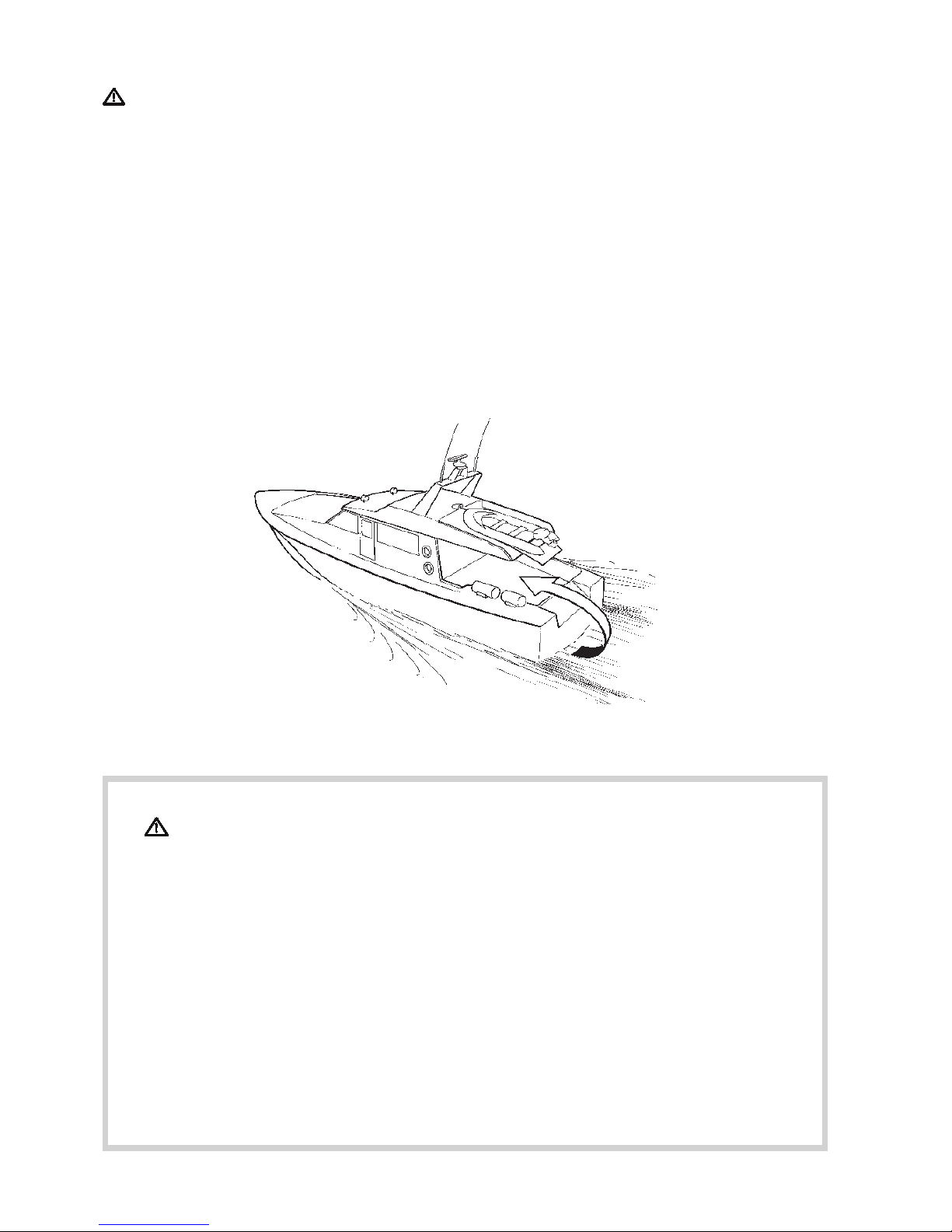
Carbon monoxide poisoning
When a boat is moving forward, it will cause a certain
vacuum to form behind the boat. In unfortunate circumstances, the suction from this vacuum can be so
great that the exhaust gases from the boat are drawn
into the cockpit or cabin and cause carbon monoxide
poisoning.
This problem is most prevailant on high, wide boats
with abrupt stern. In certain conditions, however, this
suction can be a problem on other boats, e.g. when
running with the cover up. Other factors that can increase the effect of the suction are wind conditions,
load distribution, swells, trim, open hatches and portholes, etc.
Most modern boats, however, are designed in such a
way that this problem is very rare. If suction should
arise anyway, do not open hatches or portholes at the
fore of the boat. Surprisingly, this will otherwise increase the suction. Try changing speed, trim or load
distribution instead. Try taking down/opening or in any
other way changing the setup of the cover as well.
Get in touch with your boat dealer for help in obtaining
the best solution for your boat.
Remember
Safety equipment: life jackets for everyone on board, communication equipment, distress rockets,
approved fire extinguisher, bandages, life buoy, anchor, paddle, torch, etc.
● Spare parts and tools: Impeller, fuel filter, fuses, adhesive tape, hose clips, engine oil, propeller
and tools for tasks it may be necessary to perform.
● Plan your desired route from the charts. Calculate distance and fuel consumption. Listen to weath-
er reports.
● Inform relations of your planned route for long trips. Remember to inform of changed plans or de-
lays.
● Inform the people on board of where the safety equipment is located and how it works. Make sure
there is more than one person on board that knows how to start and manoeuvre the boat safely.
This list should be supplemented with necessary safety equipment depending on the type of boat,
where and how it is being used, etc. We recommend you get in touch with a regional boat or marine
safety organisation to obtain more detailed marine safety information.

5
Safety directions for maintenance and service
Preparations
Knowledge
The instruction manual contains directions for performing normal maintenance and service in a safe and
correct manner. Read the directions carefully before
starting work.
More detailed service literature is available from your
Volvo Penta dealer.
Never perform a task unless you are absolutely sure
how it is to be carried out, call your Volvo Penta dealer for assistance instead.
Stop the engine
Stop the engine before opening or dismantling the engine hatch/hood. Maintenance and service must be
carried out with the engine stationary unless stated
otherwise in the instructions.
Prevent inadvertent start of the engine by removing
the starter key and turning off the power with the main
switch, locking it in the off position. Place a warning
sign in the driver position stating that service is in
progress.
Working on or approaching a running engine is a safety hazard. Loose clothing, hair, fingers or a dropped
tool can fasten in rotating parts and cause serious
bodily injury. Volvo Penta recommend leaving all work
requiring the engine to be running to an authorised
Volvo Penta service centre.
Lifting the engine
Always use the lifting eyes mounted on the engine (or
reverse gear) when lifting the engine. Always make
sure lifting equipment is in good condition and constructed for the lift (engine weight together with possible reverse gear and extra equipment). Use an adjustable lifting boom to ensure safe handling when lifting
the engine. All chains and wires must run parallel with
each other and as much at right-angle as possible to
the top of the engine. Note that any extra equipment
mounted on the engine can change the centre of gravity. Special lifting devices may be required to obtain
the right balance and safe handling. Never perform
service on an engine suspended only from a lifting device.
Before starting
Refit all guards and covers that have been removed
before starting the engine. Make sure there are no
tools or other objects left on the engine.
A turbocharged engine must never be started without
the air filter fitted. The rotating compressor wheel in
the turbocharger can cause severe personal injury.
There is also a risk of foreign objects being drawn in
and causing mechanical damage.
Fire and explosion
Fuel and lubricants
All fuel, most lubricants and many chemicals are
flammable substances. Always read and follow the directions on the packaging.
Work performed on the fuel system must be done on
a cold engine. Fuel leaks and spills on hot surfaces or
electrical components can cause fires.
Keep oil- and fuel-drenched rags and other hazardous
materials where they are safe in case of fire. Oil
drenched rags can self-ignite in certain conditions.
Never smoke when refuelling, topping up with oil or
when in the vicinity of the fuel station or engine room.
Non-original parts
Components in fuel, ignition and electrical systems on
Volvo Penta engines are designed and manufactured
to minimize the risk of explosion and fire in compliance with existing legislation.
The use of non-original parts can result in explosion or
fire.
Batteries
Batteries contain and generate oxyhydrogen gas, especially when charging. Oxyhydrogen is easily ignited
and extremely explosive.
Smoking, naked flames and sparks must never occur
in or close to the batteries or battery compartment.
A faulty battery connection or jumper cable can generate sparks which can cause the battery to explode.
Start spray
Never use start spray or similar start help. Explosions
can occur in the intake manifold. Risk for personal injury.

6
Hot surfaces and fluids
A hot engine always involves risk for burn injuries.
Take care with hot surfaces. E.g.: exhaust manifold,
turbocharger, oil pan, charge air pipe, starting heater,
hot coolant and warm lubricant in pipes and hoses.
Carbon monoxide poisoning
Start the engine in well ventilated spaces only. When
running in confined spaces, the exhaust gases and
crankcase gases must be evacuated.
Chemicals
Most chemicals such as glycol, anti-corrosion agent,
preservatives, degreasing agent, etc., are hazardous
to health. Always read and follow the directions on the
packaging.
Certain chemicals such as preservatives are flammable and harmful to inhale. Provide good ventilation and
use breathing protection when spraying. Always read
and follow the directions on the packaging.
Store chemicals and other hazardous materials out of
reach of children. Leave left over or used chemicals to
a destruction plant.
Cooling system
There is a risk of water entering when working on the
seawater system. Therefore, stop the engine and
close the sea cock before starting work.
Avoid opening the coolant filler cap when the engine is
warm. Steam or hot coolant may spurt out and cause
burn injuries.
If the filler cap, coolant pipe, cock, etc., must nevertheless be opened or dismantled while the engine is
warm, the filler cap must be opened carefully to release the pressure before removing it completely and
starting work. Note that the coolant can still be hot
and cause burn injuries.
Lubricating system
Hot oil can cause burn injuries. Avoid skin contact
with warm oil. Make sure the lubricating system is
depressurised before starting work. Never start or run
the engine with the oil filler cap removed or there will
be a risk of the oil being thrown out.
Fuel system
Always protect your hands when carrying out leak detection. Escaping fluids under pressure can pierce
bodily tissue and cause serious injury. Risk of blood
poisoning.
Always cover the generator if it is located under the
fuel filter. Fuel spills can damage the generator.
Electrical system
Turn off the power
Before starting work on the electrical system, the engine must be stopped and the powered turned off with
the main switch/switches. Shore power to the engine
heater, battery charger or other extra equipment fitted
to the engine must be disconnected.
Batteries
Batteries contain a highly corrosive electrolyte. Protect your eyes, skin and clothing when charging and
handing batteries. Always use protective goggles and
gloves.
In case of splashes on the skin, wash with soap and
plenty of water. In case of splashes in the eyes, rinse
immediately with plenty of water and call a doctor.
7
Aquamatic
engines
Presentation
The engines described in this instruction book are six-cylinder, in-line marine diesel engines with direct fuel injection and
fresh water cooling and equipped with a turbo-compressor and after-cooler for the intake air.
Type designations
Inboard
engines
Locating of
number plate
AQD70C
AQD70D
TAMD60A
TAMD60B
TAMD70C
TAMD70D
Engine: On the block above
the injection pump.
TAMD60: On the block in
front of the oil filters.
Reverse gear: On top
Drive 750: On the up-
per gear housing, port
side.
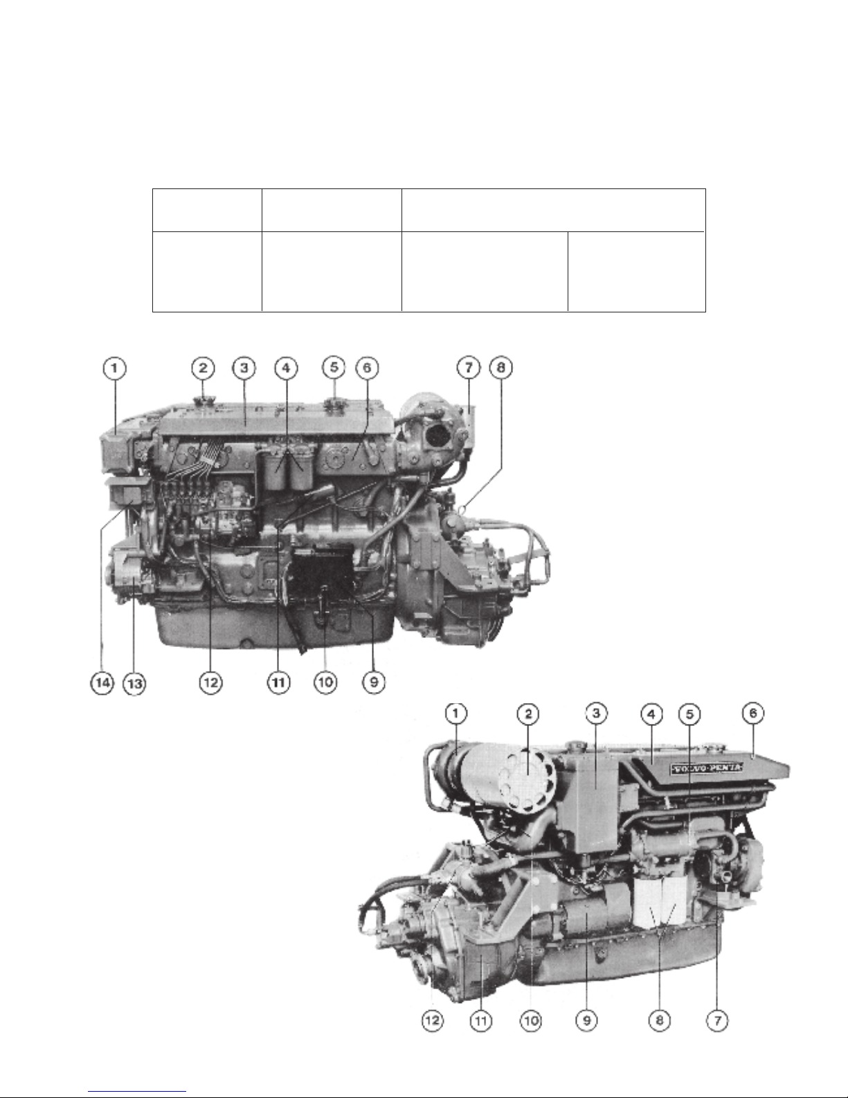
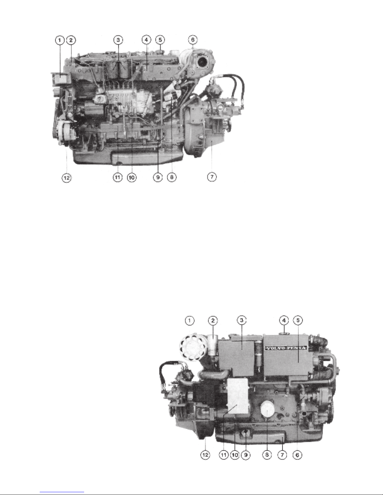
Fig. 1 Engine TAMD60B
1. Heat-exchanger
2. Coolant filler cap
3. Protecting plate
4. Fuel fine filters
5. Engine oil filler cap
6. Liquid cooled exhaust manifold
7. Filter, crankcase ventilation
8. Oil dipstick, reverse gear
9. Electric connection box with
fuses
10. Oil dipstick, engine
11. Stop solenoid
12. Injection pump
13. Alternator
14. Charging regulator
Fig. 2. Engine TAMD60A
1. Turbo-compressor
2. Air cleaner
3. After-cooler
4. Expansion tank (cooling system)
5. Oil cooler for engine
6. Connection for expansion vessel (extra
equipment)
7. Seawater pump
8. Lubricating oil filters
9. Starter motor
10. Outlet, crankcase ventilation
11. Reverse gear TD MG502
12. Oil cooler for reverse gear
8
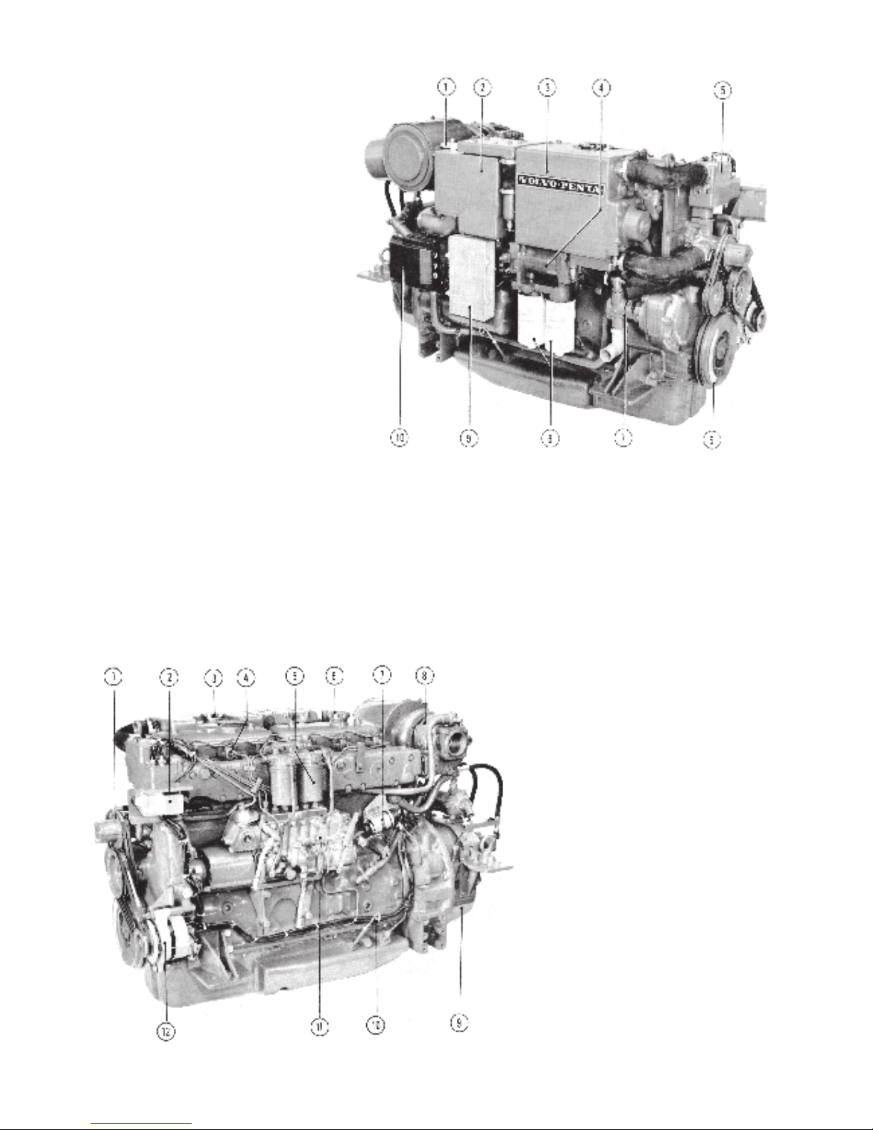
Fig 3. Engine AQD70C, TAMD70C
1. Oil scavenging pump
2. After-cooler
3. Heat exchanger
4. Oil cooler, engine
5. Thermostat housing
6. Vibration damper
7. Seawater pump
8. Oil filters
9. Relay box
10. Electric connection box with fuses
The engines are fitted with a heat exchanger for thermostatically controlled fresh water cooling of the engine block,
cylinder heads and exhaust manifold. The exhaust manifold cooling jacket is designed so that it also cools all the
exhaust ports.
The engines are lubricated by means of a pressure lubri-
cating system, where an oil pump supplies lubricating oil
to all the lubricating points in the correct quantities at all
engine speeds. The pistons in the 70-type engines are
cooled by oil fed through special nozzles located in the
engine block.
The lower part of the crankcase functions as an oil container.
The fuel system is well protected from interruptions during
running by means of effective, replaceable fuel fine filters.
On the TAMD60 engines the fuel injection pump is flange
mounted while the other engines have the pump fitted on a
bracket.
Fig. 4. Engine AQD70C, TAMD70C
1. Circulation pump
2. Charging regulator
3. Coolant filler cap
4. Injector
5. Fine filters
6. Oil filler cap
7. Stop solenoid
8. Turbo-compressor
9. Reverse gear TDMG506
10. Oil dipstick
11. Fuel injection pump
12. Alternator
9
Fig. 5. Engine TAMD70D
1. Voltage regulator
2. Thermostat housing
3. Fuel fine filters
4. Water-cooled exhaust manifold
5. Oil filler cap
6. Turbo-compressor
7. Reverse gear TD MG506
8. Stop solenoid
9. Oil dipstick
10. Fuel injection pump
11. Oil cooler
12. Alternator
The engines have wet replaceable cylinder liners which
are cooled by fresh water.
The turbo-compressor supplies fresh air to the engine
during the induction stroke. Air is supplied under pressure,
resulting in a greater degree of volumetric efficiency. The
cylinders thus receive a greater quantity of air and consequently more oxygen per stroke. In consequence the
amount of fuel injected can also be increased, which leads
to increased output.
The turbo-compressor is lubricated from the engine lubricating system and cooled from the fresh water cooling system.
In order to further increase the supply of oxygen, the air to
the engine is cooled down by an after-cooler located after
the compressor at the intake manifold.
The Aquamatic models are provided with a hydraulic pump
and a special connection flange at the reverse gear. Otherwise they are similar to the inboard engines. The hydraulic
pump, fitted at the rear side of the engine auxiliary drive
gear casing, close to the fuel injection pump coupling,
supplies oil under pressure to the power cylinder acting on
the lower, steerable part of the outboard drive. This results
in easy and effortless steering of the boat.
Fig. 6. Engine TAMD70D
1. Air cleaner
2. Crankcase ventilation filter
3. After-cooler
4. Coolant filler cap
5. Heat exchanger
6. Seawater pump
7. Oil sump
8. Oil filter
9. Level indicator, lubricating oil
(extra equipment)
10. Oil dipstick (alternative location)
11. Relay box for air pre-heater
12. Electric connection box with fuses
10
Instruments and controls
Before starting to run your new marine engine, become acquainted with the controls and instruments. Make a habit
of checking the instruments now and again while running - any abnormal readings will then be detected in time.
Instruments
The most important instruments for the engine are grouped
on a basic panel (A). There is a second panel (B) with,
among other things, an hour meter, warning lamps, warning siren and pressure gauges for the reverse gear oil
pressure and the turbo-charging pressure.
There is also a third panel (C) where a rudder indicator and
fuel gauge are fitted. (Panels B and C are optional equipment).
The location of the panels in relation to each other can be
varied, since they are built to a modular system.
A separate panel with less instruments is available for the
Flying Bridge (optional equipment). See fig. 8.
The instrument panels for TAMD60 engines are not fitted
with the control lamps 2 and 7 (Fig. 7), since these engines
do not have air pre-heating. Otherwise the equipment is the
same as for the 70-engines.
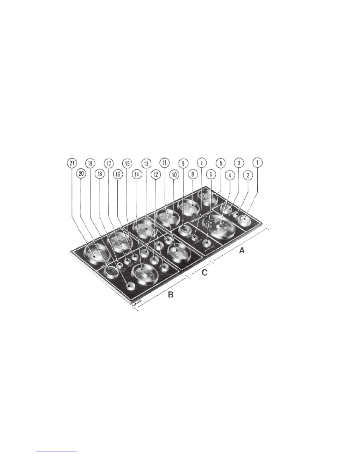
Fig. 7. Instrument panel (Panels B
and C, optional equipment)
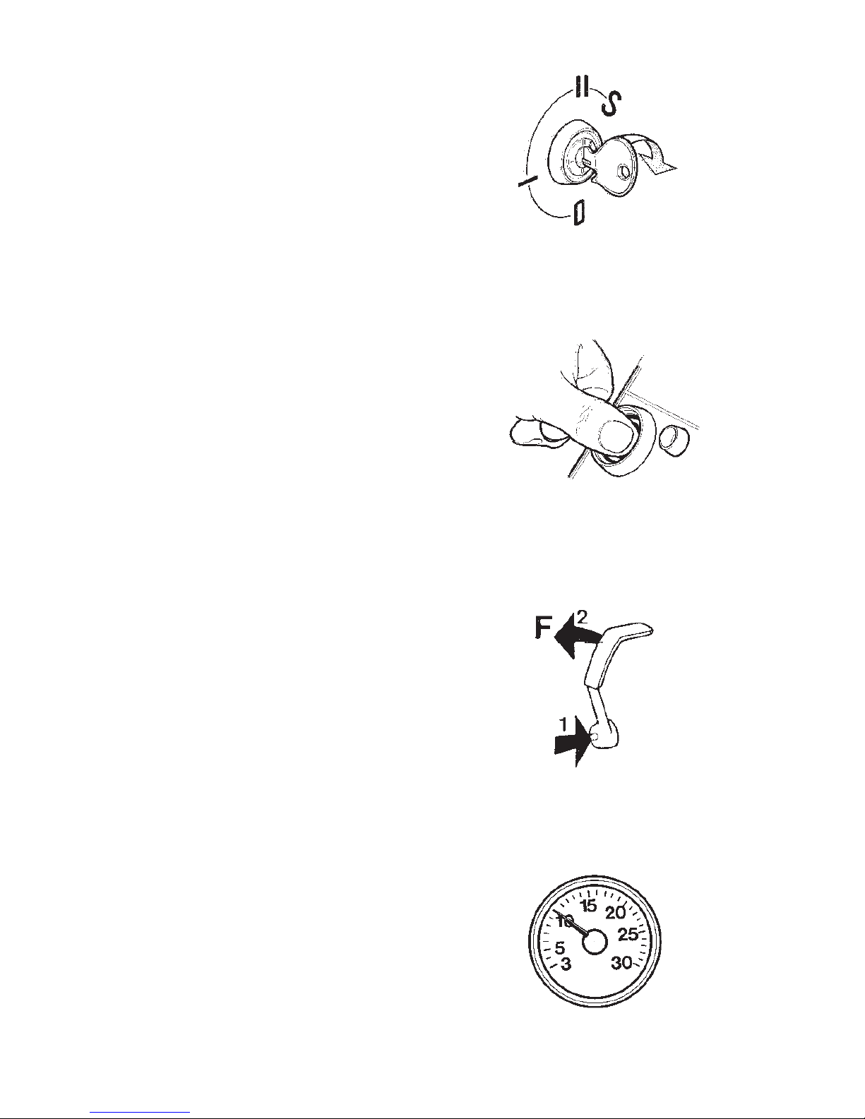
1. Key switch with 4 positions.
Position 0 – the key can be inserted and removed
Position 1 – is not used, turn key past this position
Position II – running position
Position S – pre-heater engaged. Does not apply to
TAMD60.
(See also fig. 19)
2. Control lamp - (does not apply to TAMD60). This lights
up when the air pre-heater is engaged (key turned to
position S). It remains alight while the air pre-heater is
engaged (approx. 120 sec). The pre-heater
disengages automatically.
3. Stop button - pushing it engages the stop solenoid
causing the engine to stop.
4. Revolution counter, engine speed - multiply the
figures on the scale by 100.
5. Voltmeter, charging of batteries and system voltage.
With a 24 volt system, the gauge needle (during
running) should be pointing to approx. 28 volts, but for
a 12-volt system it should be approx. 14 volts. Should
the voltage during running drop to 24 (or 12) volts, the
batteries are not being charged.
The meter is wired via the master switch and indicates 24
(or 12) volts with the engine switched off.
6. Instrument lighting - indirected lighting of all
instruments. Turn the button to vary lighting strength.
7. Control lamp - (does not apply to TAMD60) - lights
when air pre-heater has been engaged long enough
for the engine to be started. The lamp lights about 60
seconds after the key has been switched to position S
and remains alight for about 60 seconds, that is, until
the pre-heater disengages automatically.
11
8. Pressure gauge - engine lubricating oil pressure,
should be at 300-500 kPa (3-5 kp/cm2 = 43-71 psi)
during normal operation. At idling speed it should be
min. 150 kPa (1.5 kp/cm2 = 21 psi). The engine must
not be run with excessively low oil pressure.
9. Starter button - pushing it engages the starter motor.
10. Temperature gauge engine coolant - During normal
operation the temperature should be between 65° and
95°C (149-203°F). The engine must not be run for
more than a few seconds if the temperature is
excessive.
11. Rudder indicator - indicates the position of the rudder.
The middle position of the needle indicates the rudder
in neutral.
12. Push - pull switches - for extra lighting. (Max. load 5A
per switch).
13. Fuel gauge - indicates how much fuel there is in the
tank. F means full tank, E empty tank, but a small
amount of spare fuel (R) however, still remains.
14. Hour meter - registers the number of hours and minu-
tes the engine has been running.
15. Pressure gauge - reverse gear oil pressure. The
pressure should be around the values given in
”Technical Data”, pages 40 and 41.
16. Battery charging warning lamp - lights if the batteries
discharge.
17. Warning lamp - lights if the engine lubricating oil
pressure is too low.
18. Warning lamp - lights if the engine temperature
becomes excessive.
19. Push-pull switch - for extra lighting (max. load 5A)
20. Siren - engages automatically if the engine temperature becomes excessive or its oil pressure too low.
Either lamp 17 or 18 will light and indicate the type of
fault which has arisen.
21. Pressure gauge - for the turbo-compressor charging
pressure. Concerning the pressure, see ”Technical
Data”, page 40.
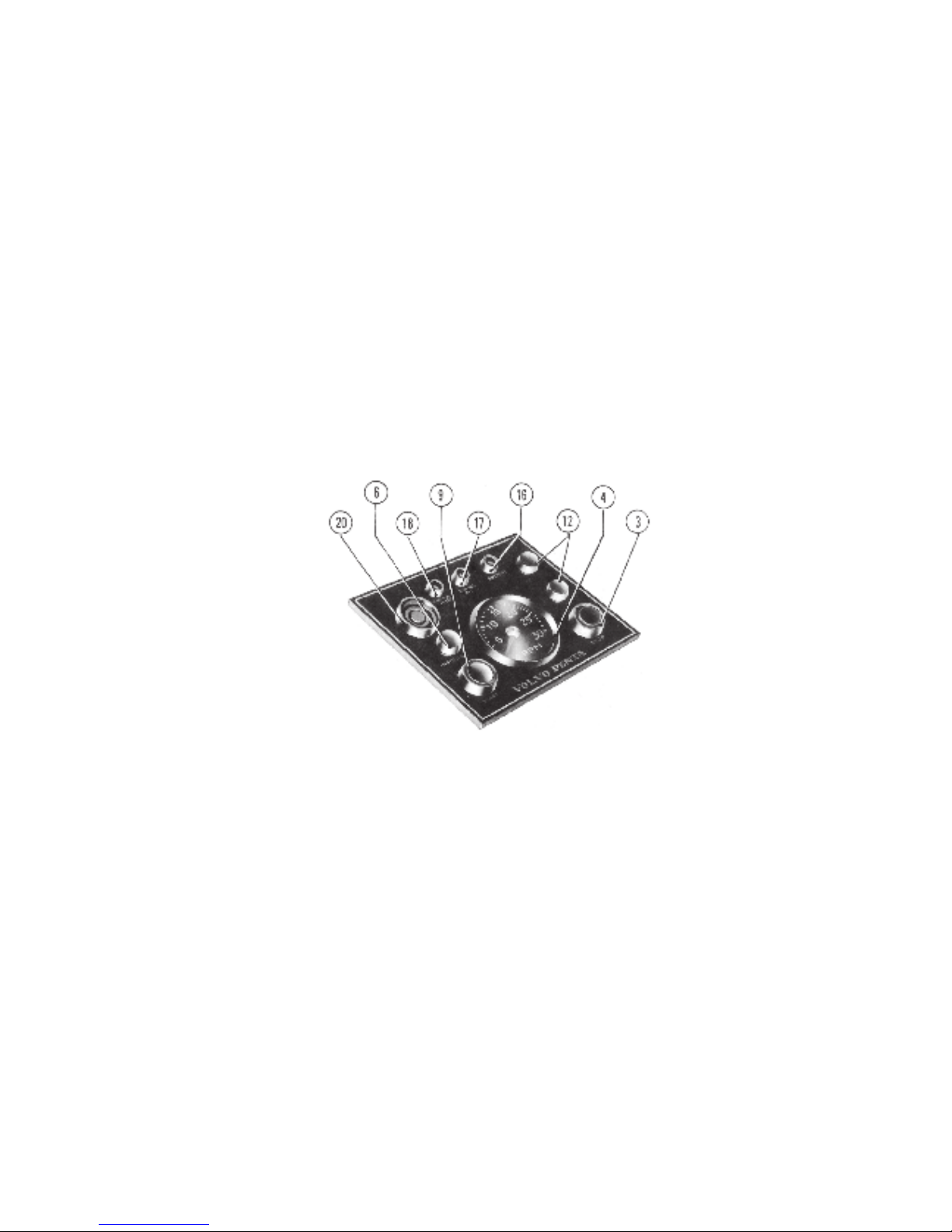
Fig. 8. Flying Bridge instrument panel, optional equipment.
The numbering on figs. 7 and 8 is similar. Flying Bridge instruments which have the same function as those on the
basic panel have been given the same numbers.
The engine can be stopped and (if it is warm) started from the Flying Bridge. On such occasions, the key on the lower instrument panel should be switched to the running position.
When the engine is cold, is should always be started from the lower control position and the air pre-heater (does not apply
to the TAMD60 engines) should be engaged before starting.
3. Stop button – pushing it in engages the stop solenoid
and the engine stops,
4. Revolution counter, engine speed – multiply the value
by 100.
6. Instrument lighting – indirect lighting of instruments
with switch pulled out.
9. Start button – pushing it in engages the starter motor.
12. Push-pull switches – for extra lighting (max. load 5A
per switch).
16. Battery charging warning lamp – lights up if the
batteries discharge.
17. Warning lamp – lights if the engine lubricating oil
pressure is too low.
18. Warning lamp – lights if the engine temperature
becomes excessive.
20. Siren – engages automatically if the engine temperature becomes excessive or its oil pressure too low.
Either one of lamps 17 or 18 also lights up and
indicates the type of fault which has arisen.
12
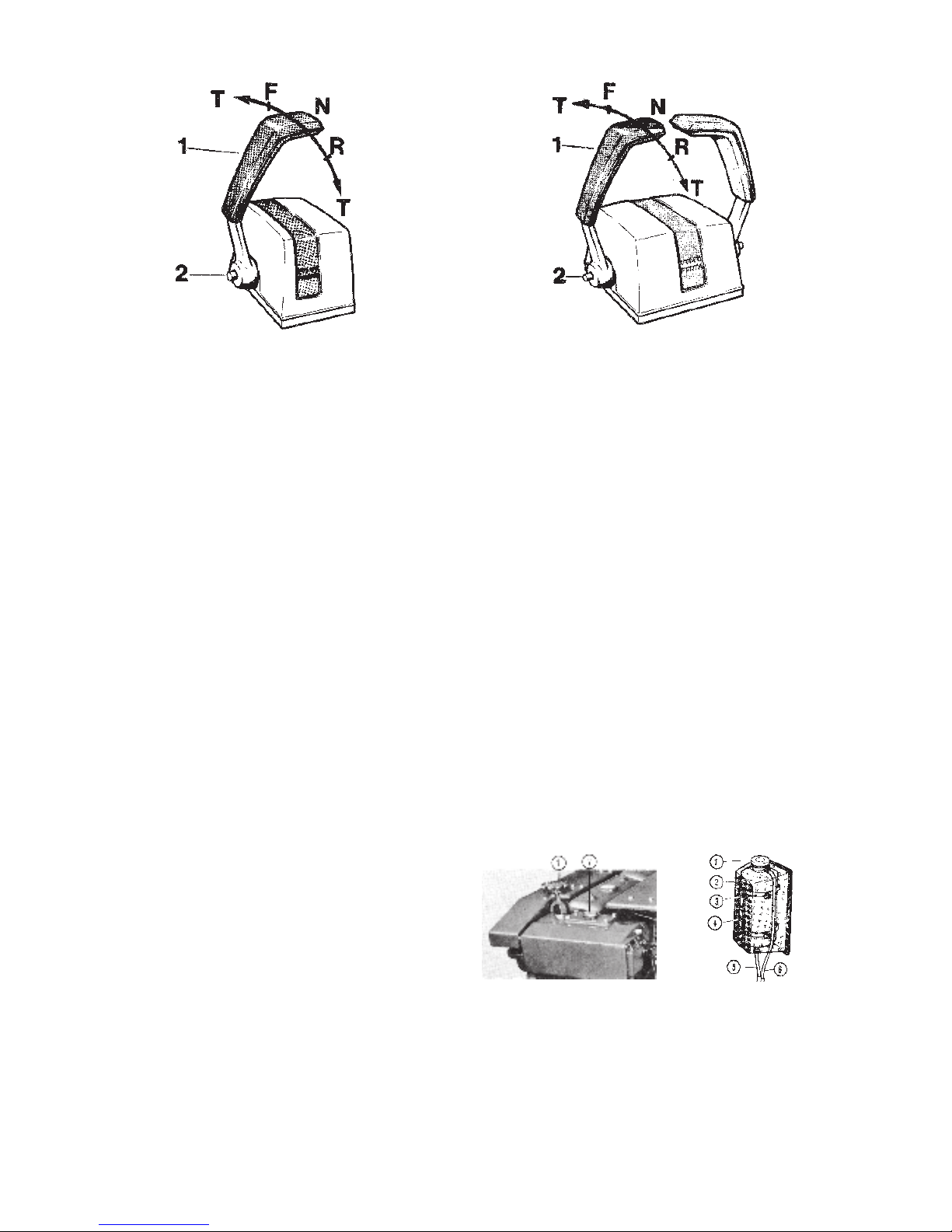
Fig. 9. Single control
Fig. 10. Twin control
Controls
Volvo Penta single lever control (single or twin), operates
both the reverse gear and the engine speed. When there
are two engines a twin control is used.
Lever (1) at N – neutral position.
From N to F – reverse gear engaged for running forward.
From N to R – reverse gear engaged for running in reverse.
T – engine speed control.
Disengaging reverse gear from control lever.
Push in the button (2) when the lever is in neutral and move
the lever forwards. The lever can then be used for controlling engine speed but with reverse gear disengaged. Take
care not to engage reverse gear unintentionally.
When it is desired to use the lever again for operating the
reverse gear, keep the button (2) pushed in and move the
lever to neutral again.
As optional equipment, the controls can have a neutral position switch, in which case the engine can only be started
with the reverse gear in neutral.
Disengageable clutch
Clutches – with or without reduction gear – have two control lever positions. Engaged – lever pushed towards engine; disengaged – lever pushed away from engine.
When engaging and disengaging the clutches, the engine
speed must not exceed 13.3 r/s (800 r/min)
Running
The following instructions apply to engines which have both standard instrumentation and optional instrument equipment. In the case of standard instruments only, the instructions apply where appropriate.
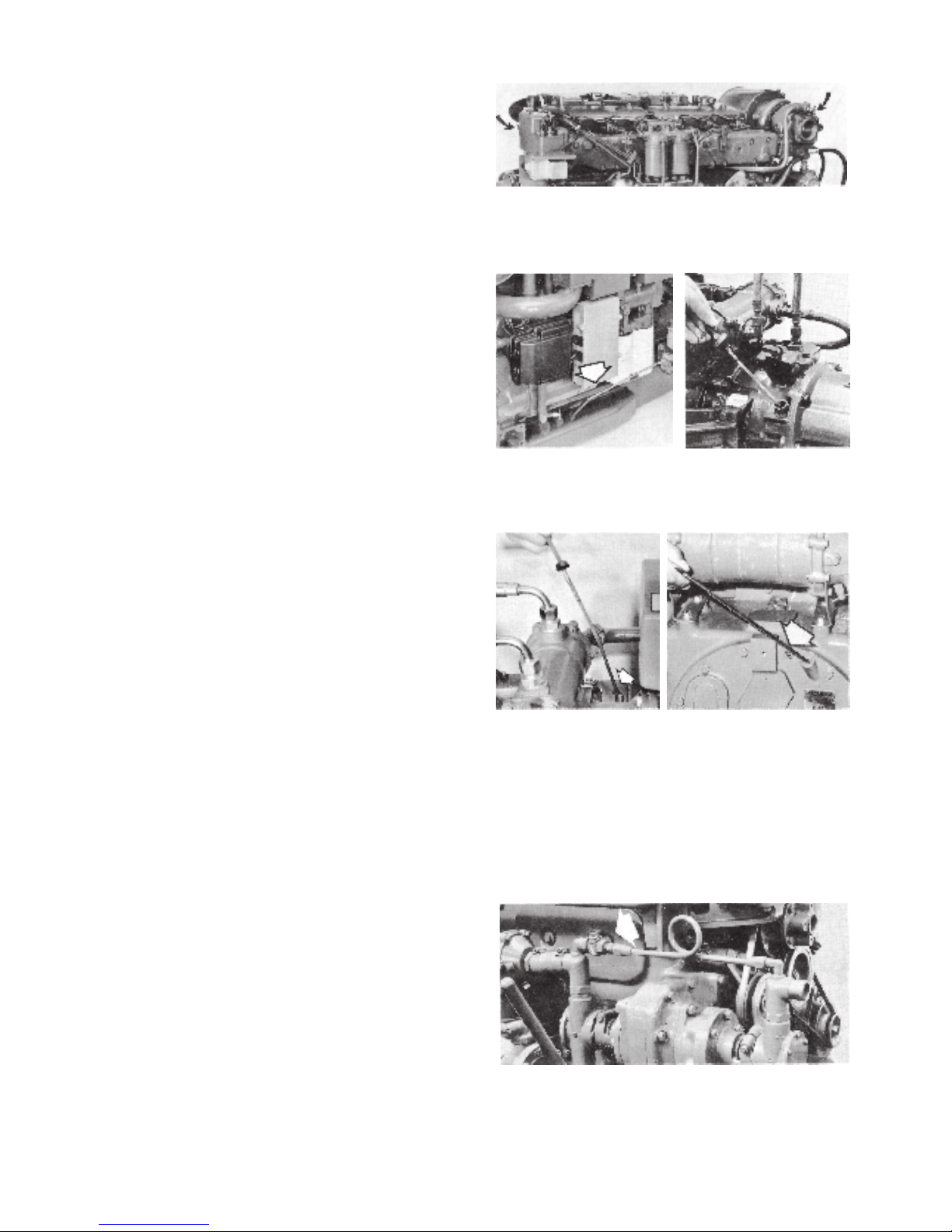
Procedure before starting
1. Coolant level. Check that the level is about 5 cm below
the expansion tank filler cap sealing surface. There
must be an air cushion for the expansion of the fluid.
On TAMD60 engines the expansion tank is next to the
heat exchanger.
As optional equipment the TAMD60 engines can also
be provided with a separately positioned expansion
tank which is made of transparent plastic and where
the level should lie between the ”min.” and ”max.”
marks.
NOTE! Remove the cap very carefully if the engine is
hot.
When adding coolant, open the venting cocks to make
sure that no air pockets form. A ventilating cock is situa-
ted on the water pipe at the turbo. For 70-type engines there is also a cock at the front of the thermostat housing.
Fig. 11. TAMD60
1. Cap on expansion tank. For
topping-up.
2. Hexagon plug on heat
exchanger. For filling the
system.
Fig. 12. Separate
expansion tank
1. Pressure cap.
2. Cover.
3. Max. level.
4. Min. level.
5. Hose from
engine.
6. Hose with open
end.
13
On the TAMD60 engines, small quantities required for
topping-up can be added to the expansion tank, but otherwise coolant should always be filled directly into the heat
exchanger through the hole for the hexagon plug, until the
engine is completely full and vented. Then close the venting cock at the turbo and screw the hexagon plug on the
heat exchanger. Thereafter, fill the expansion tank at the
side of the engine (1, fig. 11) with approx. 3 litres (0.66 Imp.
galls = 0.80 US galls) and replace the cap.
1. If the engine is connected to a cabin heater, this must
also be vented before the cap on the expansion tank or
the plug on the heat exchanger are fitted. Otherwise
the engine may be damaged due to insufficient
cooling.
Finally, fill the separate expansion tank, if fitted, to
slightly above the MIN. level.
If the engine should run abnormally hot, carefully
vent the cooling system and top up with water.
2. Lubricating oil level, engine. Check that the level is
between the marks on the dipstick. It must never be
permitted to fall below the lower mark.
(Check that the cock under the oil scavenging pump,
on the 70C-engine, is closed, see page 24.)
3. Oil level, reverse gear. The level should reach the
mark (alternatively, it should lie between the two
marks) on the dipstick. Repeat the check for Twin Disc
reverse gears whilst idling with the control in the neutral position, since this indicates the true level for this
type of reverse gear.
The oil level in the Borg Warner and SCG reverse
gears should be checked when the engine is not
running. The oil level will lie above the ”max.” mark
when the engine has been stationary long enough for
the oil to run down from the cooler and passages. To
obtain a true level reading the check should be made
immediately after the engine has been stopped.
4. Check that the seawater cocks on the engine are
closed. See the figures on page 18.
5. Open the bottom valve and the trickle-feed cock to the
bilge pump, if fitted. (Fig. 18).
6. Fuel. Check that there is sufficient fuel in the tanks and
open the fuel cocks.
7. Switch on the master switches. They should be on
when the engine is running.
NOTE! Switching off and on must never be carried out
while the engine is running, since this can damage the
charging regulator.
Fig. 13. Vent the cooling system. (The picture shows a 70C
engine.)
Fig. 14. Oil level, all engines
(the picture shows a 70-type
engine).
Fig. 15. Check the oil level
in reverse gear BW and
V-drive BW 10-05.
Fig. 16. Check the oil level
in the reverse gear TD.
Fig. 17. Check the oil level in
reverse gear SCG.
Fig. 18. Cock on trickle-feed line to bilge pump, if fitted. The
scribed line should be in line with the pipe when the cock is
open.
14
Starting
With the exception of TAMD60, the engines have an air
pre-heater fitted in the intake manifold and this should always be used in order to provide a rapid and easy start and
to reduce exhaust smoke from a cold engine.
If the engine is warm, the pre-heater does not have to be
engaged, in which case the key is turned to position II, running position. Point 2 is excluded and the engine is started
regardless of the warning lamps mentioned in point 4.
1. Turn the key to position II and check that the warning
lamps 16 and 17, figs. 7 and 8 light. The siren 20 is
switched on at the same time. Dampen the noise of the
siren by holding your thumb over it.
Always carry out this check before starting, to make
sure that warning lights and siren function; in order
to be well prepared for an emergency.
2. (This point does not apply to TAMD60 engines.) Turn
the key to position S and release it. The key will then
return to position II. The warning lamp 2, fig. 7 lights
and shows that the pre-heater has been engaged.
3. Set the control (both control levers for twin installation)
to neutral. Push in the button (1) so that the reverse
gear is disengaged. Keep the button pressed in and
then move the lever to full speed ”Forward” (2).
4. On the 70-type engines, press the starter button 9, fig.
7, immediately when the control lamp 7 lights. (The
lamp 7, which lights for about 60 seconds, lights up 60
seconds after the lamp 2.) About 2 minutes after the
key has been released from position S, the pre-heater
disengages automatically and the lights 2 and 7 go out.
The TAMD60 engines are not provided with the control
lamps mentioned in the point above and are therefore
started directly by pushing in button 9.
5. Reduce the speed to approx. 16.7 r/s (1000 r/min)
when the engine has started. Check that the warning
lamps 16 and 17 go out. The siren should stop when
lamp 17 goes out.
6. If a second starting attempt has to be made on engine
TAMD60A, the control should be moved back to “Neutral” and then re-set to full speed in order to engage the
cold-starting device again.
On other engine types, just set the control directly to full
speed, at the same time as the pre-heater is reengaged for the 70-type engines.
7. Never race a cold engine. The lubricating oil is
viscous in its cold condition and there is always risk of
seizing if the engine is raced.
Fig. 19. Position 0, the key can be inserted and removed.
Position 1, not used.
Position II, running position
Position S, pre-heater engaged (not applicable to
TAMD60)
Fig. 20. The sound of the siren can be dampened by placing the thumb over it during the pre-heating period (on the
70-type engines)
Fig. 21. Disengaging the reverse gear from the control.
Fig. 22. Engine speed
 Loading...