

Page 1

Engine repair
MD22, TMD22, TAMD22
Workshop Manual
2(0)
A
Page 2

Page 3

1
Engine repair
Marine Engines
MD22 • TMD22 • TAMD22
Contents
General Information
Safety Information ............................................. 3
General Information .......................................... 6
Repair instructions ............................................ 7
Special tools ....................................................... 10
Identification Numbers ...................................... 12
Introduction to the engine ................................ 13
Cylinder head
General................................................................ 16
Repair Instructions
Camshaft cover, replacement (12A-01) .............. 17
Valve clearance, check (12A-02) ........................ 18
Valve clearance, adjustment (12A-03) ................19
Front sealing ring, replacement (12A-04)............ 21
Rear sealing ring, replacement (12A-05) ............ 22
Camshaft, replacement (12A-06) ........................ 23
Cylinder head assembly, replacement (12A-07). 24
Valves and valve springs, replacement (12A-08) 28
Valves and valve springs, inspection (12A-09) ... 29
Valve guides, inspection (12A-10) ...................... 30
Valve guides, replacement (12A-11) ................... 30
Cylinder head, inspection (12A-12) ..................... 31
Valve seats, grinding (12A-13) ............................ 32
Valve seats, replacement (12A-14)..................... 33
Piston and connecting rod assembly
General................................................................ 34
Repair Instructions
Big ends, replacement (13A-01) .......................... 35
Big ends, inspection (13A-02) ............................. 36
Piston and connecting rod assembly,
replacement (13A-03) .......................................... 36
Piston rings, replacement (13A-04) ..................... 39
Piston and connecting rod,
assembly / dismantling (13A-05) ......................... 40
Piston and piston rings, inspection (13A-06) ...... 41
Connecting rod, inspection (13A-07) ................... 42
Connecting rod bushing, replacement (13A-08).. 42
Crankshaft assembly
General................................................................ 43
Repair Instructions
Crankshaft pulley, replacement (14A-01) ............ 44
Front sealing ring, replacement (14A-02)............ 45
Rear sealing ring, replacement (14A-03) ............ 47
Crankshaft axial clearance, checking (14A-04) .. 48
Thrust bearing, replacement (14A-05) ................ 48
Main bearings, replacement (14A-06) ................. 50
Main bearings, inspection (14A-07) ..................... 51
Crankshaft, replacement (14A-08) ...................... 52
Crankshaft, inspection (14A-09) ......................... 53
Timing cover and sprocket
General................................................................ 54
Repair Instructions
Timing cover outer, replacement (15A-01).......... 55
Timing belt, inspection (15A-02) ......................... 56
Timing belt, tension (15A-03) .............................. 57
Timing belt, replacement (15A-04) ...................... 58
Fuel injection pump pulley,
replacement (15A-05) .......................................... 59
Camshaft pulley, replacement (15A-06).............. 61
Crankshaft pulley, replacement (15A-07) ............ 62
Timing cover inner, replacement (15A-08).......... 65
Cylinder block
General................................................................ 67
Repair Instructions
Cylinder block, replacement (16A-01)................. 67
Cylinder block, inspection (16A-02) .................... 69
Cylinder bore, honing (16A-03)............................ 70
Page 4

2
Engine settings
General................................................................71
Repair Instructions
Setting the 1st piston at top dead center of
compression stroke (17A-01)..............................72
Valve timings, checking and adjustment
(17A-02)...............................................................72
Injection timing, checking / adjusting..................73
Lubrication system
General................................................................75
Repair Instructions
Oil filter, replacement (18A-01)...........................76
Oil filter adapter, replacement (18A-02)..............76
Oil pan, replacement (18A-03)............................77
Oil screen and suction pipe, replacement
(18A-04)...............................................................78
Oil screen and suction pipe, inspection
(18A-05)...............................................................78
Oil pump, replacement (18A-06).........................79
Oil pump, inspection (18A-07).............................81
Relief valve, replacement (18A-08).....................82
Relief valve, inspection (18A-09)........................82
Fuel system
General................................................................83
Repair Instructions
Fuel filter, replacement (19A-01).........................84
Injectors, fault-tracing..........................................85
Injectors, replacement (19A-02)..........................85
Feed pump, replacement (19A-03)......................86
Feed pump, reconditioning (19A-04)...................87
Fuel supply pressure, checking (19A-05)...........88
Fuel injection pump, replacement (19A-06).........89
Idling speed, adjustment (19A-07)......................91
Fuel injection system, bleeding (19A-08)............92
Cooling system
General................................................................93
Repair Instructions
Coolant, draining (20A-01)...................................95
Coolant, filling (20A-2).........................................96
Sea water circuit, draining (20A-03)....................97
Thermostat, replacement (20A-04).....................98
Thermostat, checking..........................................98
Circulation pump, replacement (20A-05)............99
Sea water pump, replacement (20A-06).............100
Sea water pump, reconditioning (20A-07)..........101
Installation and adapter plate for seawater
pump, replacement (20A-08)..............................104
Oil cooler, replacement (20A-09).......................105
Heat exchanger / manifold / coolant tank,
replacement (20A-10).........................................107
Heat exchanger, reconditioning (20A-11)...........109
Charge air cooler (CAC), reconditioning
(20A-12)..............................................................111
Flywheel, flywheel cover
General...............................................................112
Repair Instructions
Flywheel, replacement (21A-01).........................112
Ring gear, replacement (21A-02).......................112
Flywheel cover, replacement (21A-03)..............114
Electrical system
General...............................................................116
Generator............................................................116
Starter motor.......................................................116
Glow plugs..........................................................116
Repair Instructions
Generator, replacement (22A-01).......................117
Generator, maintenance.....................................118
Generator, fault-tracing......................................118
Starter motor, replacement (22B-01).................119
Starter motor, maintenance (22B-02).................119
Starter motor, checking (22B-03).......................120
Glow plugs, replacement (22C-01).....................120
Glow plugs, checking power supply / continuity121
Glow plugs, function check................................121
Wiring Diagram...................................................122
Intake and exhaust system
Turbocharger (TC)(TMD22, TAMD22),
replacement........................................................125
Boost pressure control valve, checking.............126
Page 5
3
General instructions
Safety information
Introduction
This Workshop Manual contains descriptions and
repair instructions for Volvo Penta products or product versions contained in the contents list. Ensure
that the correct workshop literature is being used.
Read the safety information and the Workshop
Manual “General Information” and “Repair Instructions” carefully before starting work.
Important
In this book and on the product, you will find the following special warning symbols.
WARNING! If these instructions are not followed there is a danger of personal injury, extensive damage to the product or serious mechanical malfunction.
IMPORTANT! Used to draw your attention to
something that can cause damage, product
malfunction or damage to property.
NOTE! Used to draw your attention to important information that will facilitate work or operations.
Below is a summary of the risks and safety precautions you should always observe or carry out when
operating or servicing the engine.
Immobilize the engine by turning off the power
supply to the engine at the main switch
(switches) and lock it (them) in the OFF position before starting work. Set up a warning notice at the engine control point or helm.
Generally, all servicing should be carried out
with the engine switched off. However, some
work, certain adjustments for example, require
that the engine is running when they are carried out. Approaching a running engine is dangerous. Loose clothing or long hair can catch
in rotating parts and cause serious personal
injury.
If working in proximity to a running engine,
careless movements or a dropped tool can result in personal injury. Avoid burns. Take precautions to avoid hot surfaces (exhausts, turbochargers, charge air pipes and starter elements etc.) and liquids in supply lines and
hoses when the engine is running or has been
turned off immediately prior to starting work
on it. Reinstall all protective parts removed
during service operations before starting the
engine.
Check that the warning or information decals
on the product are always clearly visible. Replace decals that have been damaged or painted over.
Engines with turbochargers: Never start the
engine without installing the air cleaner (ACL)
filter. The rotating compressor in the turbocharger can cause serious personal injury.
Foreign objects entering the intake ducts can
also cause mechanical damage.
Never use start spray or similar to start the
engine. An explosion may occur in the inlet
manifold. Danger of personal injury.
Avoid opening the filler cap for the engine
coolant system (freshwater cooled engines)
when the engine is still hot. Steam or hot coolant can spray out. Open the coolant filler cap
carefully and slowly to release the pressure
before removing the cap completely. Take
great care if a cock, plug or engine coolant
line must be removed from a hot engine. It is
difficult to anticipate in which direction steam
or hot coolant can spray out.
Hot oil can cause burns. Avoid getting hot oil
on the skin. Ensure that the lubrication system
is not under pressure before carrying out any
work. Never start or operate the engine with
the oil filler cap removed, otherwise oil could
be ejected.
Stop the engine and close the seacock valve
before carrying out operations on the engine
cooling system.
Only start the engine in a well-ventilated area.
If operating the engine in an enclosed space,
ensure that exhaust gases and crankcase
ventilation emissions are extracted from the
workshop area.
Page 6
4
General instructions
Always use protective goggles where there is
a danger of pieces of metal, sparks from
grinding, acid or other chemicals being thrown
into your eyes. Eyes are very sensitive. Injury
to them can lead to the loss of sight!
Avoid skin contact with oil! Long-term or repeated contact with oil can remove the natural
oils from your skin. This can result in irritation, dry skin, eczema and other skin problems. Used oil is more dangerous to health
than new oil. Use protective gloves and avoid
using oil-soaked clothes and rags. Wash regularly, especially before meals. Use the correct
barrier cream to prevent dry skin and to make
cleaning your skin easier.
Most chemicals used in products (engine and
transmission oils, glycol, petrol and diesel oil)
and workshop chemicals (solvents and paints)
are hazardous to health Read the instructions
on the product packaging carefully! Always
follow safety instructions (using breathing apparatus, protective goggles and gloves for example). Ensure that other personnel are not
unwittingly exposed to hazardous substances
(by inhalation for example). Ensure that ventilation is good. Handle used and excess chemicals according to the instructions.
Be extremely careful when tracing leaks in the
fuel system and testing fuel injection nozzles.
Use protective goggles! The jet ejected from a
fuel injection nozzle is under very high pressure. It can penetrate body tissues and cause
serious injury Danger of blood poisoning.
All fuels and many chemicals are inflammable.
Ensure that a naked flame or sparks cannot
ignite fuel or chemicals. Combined with air in
certain ratios, petrol, some solvents and hydrogen from batteries are easily inflammable
and explosive. Smoking is prohibited! Ensure
that ventilation is good and that the necessary
safety precautions have been taken before
carrying out welding or grinding work. Always
have a fire extinguisher to hand in the workplace.
Store oil and fuel-soaked rags and fuel and oil
filters safely. In certain conditions, oil-soaked
rags can spontaneously ignite. Replaced fuel
and oil filters are environmentally harmful
waste and should be disposed of at proper
disposal areas together with engine and transmission oil, contaminated fuel, old paint, degreasing agents, and cleaning residue.
Never allow a naked flame or electric sparks
near the batteries. Never smoke in the vicinity
of the batteries. The batteries give off hydrogen gas during charging which when mixed
with air can form an explosive gas - oxyhydrogen. This gas is easily ignited and highly volatile. Incorrect connection of the battery can
cause a single spark which is sufficient to
cause an explosion with resulting damage. Do
not disturb the battery connections when starting the engine (spark risk) and do not lean
over batteries.
Always ensure that the positive and negative
battery leads are correctly installed on the
corresponding terminal posts on the batteries.
Incorrect installation can result in serious
damage to electrical equipment. Refer to the
wiring diagram.
Always use protective goggles when charging
and handling the batteries. The battery electrolyte contains extremely corrosive sulfuric
acid. If this comes into contact with the skin,
wash immediately with soap and plenty of water. If battery acid comes into contact with the
eyes, immediately flush with copious amounts
of water and obtain medical assistance.
Turn off the engine and switch off the power at
the main switch(es) before carrying out work
on the electrical system.
Page 7
5
General instructions
Use the lifting eyes mounted on the engine /
reverse gear when lifting the drive unit.
Always check that lifting equipment is in good
condition and has sufficient load capacity to
lift the engine (engine weight including reverse
gear and any extra equipment installed).
Use an adjustable lifting beam or lifting beam
specifically for the engine to raise the engine
to ensure safe handling and to avoid damaging
engine parts installed on the top of the engine.
All chains and cables should run parallel to
each other and as perpendicular as possible in
relation to the top of the engine.
If extra equipment is installed on the engine,
thereby altering its center of gravity, a special
lifting device is required to achieve the correct
balance for safe handling.
Never carry out work on an engine suspended
on a hoist.
Never remove heavy components alone, even
where secure lifting equipment such as secured blocks are being used. Even where lifting equipment is being used, it is best to carry
out the work with two people; one to operate
the lifting equipment and the other to ensure
that components are not trapped and damaged
when being lifted.
When working on-board, ensure that there is
sufficient space to remove components without danger of injury or damage.
Components in the electrical system, ignition
system (gasoline engines) and fuel system on
Volvo Penta products are designed and constructed to minimize the risk of fire and explosion. The engine must not be run in areas
where there are explosive materials.
Always use fuels recommended by Volvo Penta. Refer to the Instruction Book. The use of
other grades of fuel can damage the engine.
On a diesel engine, poor quality fuel can
cause the control rod to seize and the engine
to overrev with the resulting risk of damage to
the engine and personal injury. Poor fuel quality can also lead to higher maintenance costs.
Page 8
6
General information
Certificated engines
If you own an engine certificated for any area
where exhaust emissions are regulated by law,
the following is important:
Certification means that an engine type is inspected
and approved by the authorities. The engine manufacturer guarantees that all engines manufactured of
that type correspond to the certified engine.
This places special requirements for maintenance and service as follows:
• The maintenance and service intervals recommended by Volvo Penta must be observed.
• Only genuine Volvo Penta replacement parts
may be used.
• The service of injection pumps and injectors or
pump settings must always be carried out by
an authorized Volvo Penta workshop.
• The engine must not be modified in any way except with accessories and service kits approved by Volvo Penta.
• No modifications to the exhaust pipes and air
supply ducts for the engine room may be undertaken.
• Seals may only be broken by authorized personnel.
In addition, the general instructions contained in the
Instruction Manual concerning operation, service
and maintenance must be followed.
IMPORTANT! Late or inadequate maintenance
/ service or the use of spare parts other than
Volvo Penta original spare parts will invalidate
AB Volvo Penta’s responsibility for the engine
specification being in accordance with the certificated variant.
Volvo Penta accepts no responsibility or liability for any damage or costs arising due to the
above.
About the workshop manual
This Service Manual contains descriptions and instructions for the repair of the following engines in
standard format: MD22A, MD22L-A, MD22L-B,
MD22P-B, TMD22A, TMD22-A, TMD22-B, TMD22PC, TAMD22P-B. This Service Manual can show operations carried out on any of the engines listed
above. As a result, the illustrations and pictures in
the manual showing certain engines components,
do not in some cases apply to all the engines listed
above. However, the repair and service operations
described are the same in all essential details.
Where they are not the same, this is stated in the
manual. Where the difference is considerable, the
operations are described separately. The engine
designation and engine number are displayed on the
identification plate (see the chapter “Identifying
numbers”). The engine designation and number
should be given in all correspondence about the engine.
This Workshop Manual has been developed primarily for Volvo Penta service workshops and qualified
personnel. Personnel using this book are assumed
to have a grounding in marine drive systems and
able to carry out the related mechanical and electrical work.
Volvo Penta is continuously developing their products. We therefore reserve the right to make changes. All the information contained in this book is
based on product data available at the time of going
to print. Any essential changes or modifications introduced into production or updated or revised service methods introduced after the date of publication
will be provided in the form of Service Bulletins.
Spare parts
Replacement parts for electrical and fuel systems
are subject to statutory requirements (US Coast
Guard Safety Regulations for example). Volvo Penta Genuine parts meet these requirements. Any
type of damage which results from the use of nonoriginal Volvo Penta replacement parts for the product will not be covered under any warranty provided
by Volvo Penta.
Page 9
7
Repair Instructions
The working methods described in the Service Manual apply to work carried out in a workshop. The engine has been removed from the boat and is installed in an engine fixture. Unless otherwise stated
reconditioning work which can be carried out with
the engine in place follows the same working method.
Warning symbols occurring in the Workshop Manual (for their meaning see Safety information)
WARNING!
IMPORTANT!
NOTE!
are not in any way comprehensive since it is impossible to predict every circumstance under which
service work or repairs may be carried out. For this
reason we can only highlight the risks that can arise
when work is carried out incorrectly in a wellequipped workshop using working methods and
tools developed by us.
All procedures for which there are Volvo Penta special tools in this Workshop Manual are carried out
using these. Special tools are developed to rationalize working methods and make procedures as safe
as possible. It is therefore the responsibility of any
person using tools or working methods other than
the ones recommended by us to ensure that there is
no danger of injury, damage or malfunction resulting
from these.
In some cases there may be special safety precautions and instructions for the use of tools and chemicals contained in this Workshop Manual. These
special instructions should always be followed if
there are no separate instructions in the Workshop
Manual.
Certain elementary precautions and common sense
can prevent most risks arising. A clean workplace
and engine eliminates much of the danger of injury
and malfunction.
It is of the greatest importance that no dirt or foreign particles get into the fuel system, lubrication
system, intake system, turbocharger, bearings and
seals when they are being worked on. The result can
be malfunction or a shorter operational life.
Our Joint responsibility
Every engine consists of many systems and components that work together. If one component deviates from the technical specifications this can have
dramatic consequences on the environmental impact of the engine even if it is otherwise in good
running order. It is therefore vital that wear tolerances are maintained, that systems that can be adjusted are adjusted properly and that Volvo Penta
Genuine Parts as used. The engine Maintenance
Schedule must be followed.
Certain systems (components in the fuel system for
example) may require specialist expertise and test
equipment. Some components are sealed at the factory for environmental reasons. No work should be
carried out on sealed components except by authorized personnel.
Bear in mind that most chemicals used on boats are
harmful to the environment if used incorrectly. Volvo Penta recommends the use of biodegradable degreasing agents for cleaning engine components,
unless otherwise stated in a workshop manual.
Take special care when working on-board, that oil
and waste is taken for destruction and is not accidentally pumped into the environment with bilge water.
Tightening torque
Tightening torques for vital joints that must be tightened with a torque wrench are listed in Workshop
manual “Technical Data”: and are in certain cases
contained in work descriptions in this Manual. All
torques apply for cleaned threads, screw heads and
mating surfaces. Torques apply for lightly oiled or
dry threads. If lubricants, locking fluid or sealing
compound are required for a screwed joint this information will be contained in the work description.
Where no tightening torque is stated for a joint use
the general tightening torques according to the tables below. The tightening torques stated are a
guide and the joint does not have to be tightened using a torque wrench.
Dimension Tightening torques
Nm
M5 .................. 5
M6 .................. 10
M8 .................. 20
M10 ................ 40
M12 ................ 70
M14 ................ 115
Page 10

8
General instructions
Protractor tightening torques
Tightening using both a torque setting and a protractor angle requires that first the recommended torque
is applied using a torque wrench and then the recommended angle is added according to the protractor scale. Example: a 90° protractor tightening
means that the joint is tightened a further 1/4 turn in
one operation after the stated tightening torque has
been applied.
Locknuts
Do not re-use lock nuts that have been removed
during dismantling as they have reduced service life
when re-used - use new nuts when assembling or
reinstalling. For lock nuts with a plastic insert such
as Nylock® the tightening torque stated in the table
is reduced if the Nylock® nut has the same head
height as a standard hexagonal nut without plastic
insert. Reduce the tightening torque by 25% for 8
mm bolt sizes or larger. Where Nylock® nuts are
higher, or of the same height as a standard hexagonal nut, the tightening torques given in the table apply.
Strength classes
Screws and nuts are divided into different strength
classes, the class is indicated by the number on the
bolt head. A high number indicates stronger material, for example a bolt marked 10-9 indicates a higher strength than one marked 8-8. It is therefore important that bolts removed during the disassembly
of a bolted joint must be reinstalled in their original
position when assembling the joint. If a bolt must be
replaced check in the replacement parts catalogue
to make sure the correct bolt is used.
Sealing compound
A number of sealants and locking liquids are used
on the engines. The agents have varying properties
and are used for different types of jointing
strengths, operating temperature ranges, resistance
to oil and other chemicals and for the different materials and gap sizes in the engines.
To ensure service work is correctly carried out it is
important that the correct sealant and locking fluid
type is used on the joint where the agents are required.
In this Volvo Penta Service Manual the user will find
that each section where these agents are applied in
production states which type was used on the engine.
During service operations use the same agent or an
alternative from a different manufacturer.
Ensure that mating surfaces are dry and free from
oil, grease, paint and anti-corrosion agent before
applying sealant or locking fluid.
Always follow the manufacturer’s instructions for
use regarding; temperature range, curing time and
any other instructions for the product.
Two different basic types of agent are used on the
engine. These are:
RTV agent (Room temperature vulcanizing). Used
for gaskets, sealing gasket joints or coating gaskets. RTV agent is clearly visible when a component has been dismantled; old RTV must be removed before the joint is resealed.
The following RTV agents are mentioned in the
Service Manual: Loctite® 574, Volvo Penta 8408791, Permatex
®
No.3, Volvo Penta P/N 1161099-5, Permatex
(r)
No.
77. Old sealant can be removed using denatured alcohol in all cases.
Anaerobic agents. These agents cure in an absence
of air. They are used when two solid parts, for example cast components, are installed face-to-face
without a gasket. Used to seal and lock plugs, stud
threads, stopcocks, oil pressure sensors etc. Cured
anaerobic agents are glassy and the agents are
colored to make them visible. Cured anaerobic
agents are extremely resistant to solvents and the
old agent cannot be removed. When reinstalling the
part is carefully degreased and then new sealant is
applied.
The following anaerobic agents are mentioned in the
Service Manual: Loctite® 572 (white), Loctite® 241
(blue).
NOTE! Loctite® is the registered trademark of Loctite Corporation,
Permatex® is the registered trademark of the Permatex Corporation.
Page 11

9
General instructions
Safety precautions for Fluorine
rubber
Fluorine rubber is a common material in sealing
rings for shafts and O rings.
When fluorine rubber is exposed to high temperatures (over 300°C) it can release highly corrosive
hydrofluoric acid. Exposing the skin to this chemical can cause serious burns. If splashed in the eyes
it can cause malignant ulcers. Inhaling the fumes
can damage the respiratory passages.
WARNING! Take the greatest care when
working on engines that have been operating
at high temperatures, for example an overheated engine that has seized or an engine involved in a fire. The seals must never be
burned off when disassembling or be burnt afterwards in anything other than a special disposal site.
• Always used chloroprene rubber gloves (gloves
for handling chemicals) and protective goggles.
• Treat removed seals in the same way as corrosive acid. All remains, even the ash can be extremely corrosive. Never use compressed air
jets for blowing clean.
• Put old seal remnants in a plastic container,
close it and stick a warning label on it. Wash
gloves under running water before removal.
The following seals may contain fluorine rubber:
Crankshaft, camshaft and intermediate shaft seals.
O rings, wherever used. O rings for cylinder liner
sealing are almost always fluorine rubber.
Note that seals which have not been exposed to
high temperatures can be handled normally.
Page 12
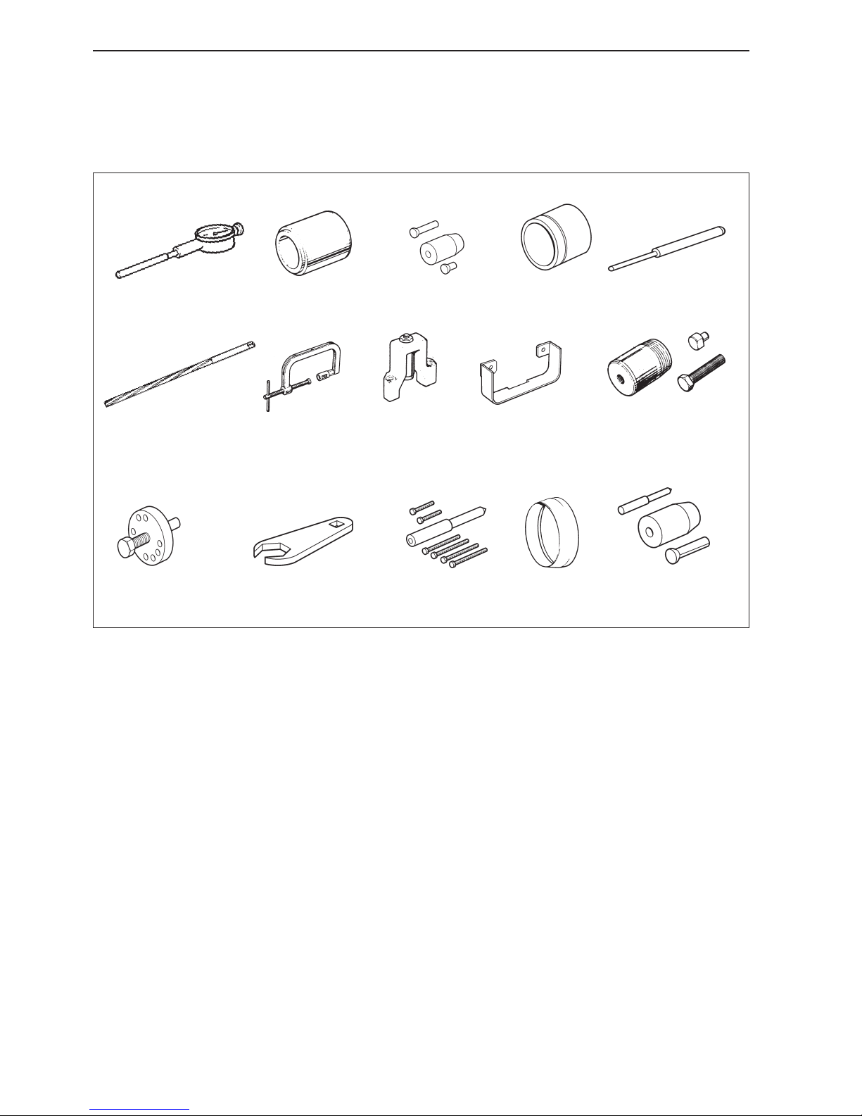
10
Special tools
885 026
884 955
8858 018
885 019
885 020
885 021
885 022
885 023
885 024 885 025
Special tools
884955-6 Dial gauge assembly
885018-2 Installation tools for front stuffing box,
camshaft.
885019-0 Puller for rear stuffing box, camshaft.
885020-8 Installation tools for rear stuffing box,
camshaft.
885021-6 Presser / depresser for valve guides.
885022-4 Reamer for new valve guides.
885023-2 Valve spring tensioner.
885024-0 Camshaft mounting seats (set of three)
885025-7 Camshaft locking.
885 030885 028885 027 885 029 885 031
885026-5 Puller for front stuffing box, camshaft.
885027-3 Puller for injection pump and crankshaft
pulleys (main tool).
885028-1 Dismantling / assembly wrench for the
stop solenoid for the fuel injection pump
885029-9 Adapters for use with 885027.
885030-7 Protective socket for rear stuffing box,
crankshaft.
885031-5 Puller for front stuffing box, crankshaft.
In all cases where it is practical the tool number, except for the final digit, has been stamped on the tool, The
final digit (after the hyphen) is a control number.
Page 13
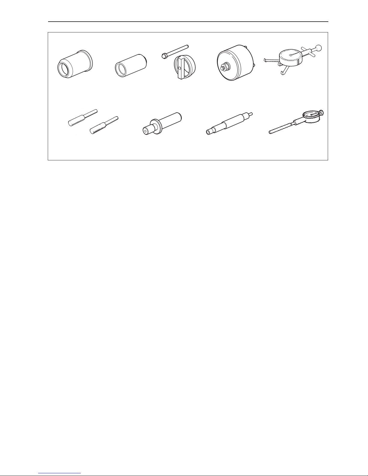
11
Special tools
885 036885 035885 034885 033885 032
885 139885 041885 038885 037
885032-3 Protective socket for front stuffing box,
crankshaft.
885033-1 Installation tool for front stuffing box,
crankshaft.
885034-9 Puller for rear stuffing box, crankshaft.
885035-6 Installation tool for rear stuffing box,
crankshaft.
885036-4 Belt tension gauge for timing belt.
885037-2 Adjustment drifts for the camshaft and
crankshaft.
885038-0 Alignment adapter for installing the sea-
water pump.
885041-4 Adapter for checking compression.
885139-6 Dial gauge assembly (TMD22P,
TAMD22 only)
Page 14
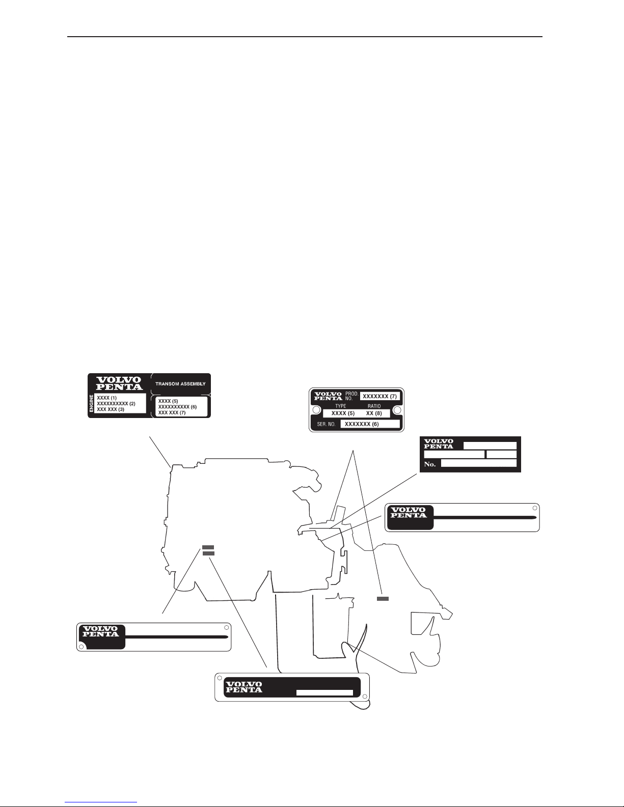
12
Identifying numbers
Your engine and transmission has identification plates with identification numbers. This information should always be quoted when ordering replacement parts. The appearance and location of identification plates is
shown below. The figures in brackets refer to the location of the identification numbers on the identification
plate.
Engine
Product designation (1)
Serial number (2)
Product number (3)
Certification number (4)
Drive / Shield / Reverse gear
Product designation (5)
Serial number (6)
Product number (7)
Gear ratio (8)
General information
Engine and transmission decal
xxx (5) (8) xxxxxx (7)
N
o
. xxxxxxxxxx (6)
XXXXXX (7)
XXX (5)
XXXXXXXXXX (6)
XX (8)
xxxx (1) xxxxxx (3)
No. xxxxxxxxxx (2)
SX-drive/Shield
xxxxxxxxxx (4)
EMISSION APPROVED IN ACCORDANCE TO THE
BODENSEE SCHIFFAHRTS ORDNUNG ANLAGE C.
APPROVAL NO:
Reverse gear MS25/HS25
S-drive / Reverse gear MS2
Certification plate
Engine plate
Page 15
13
14
15
1 2
3
4
19
17
18
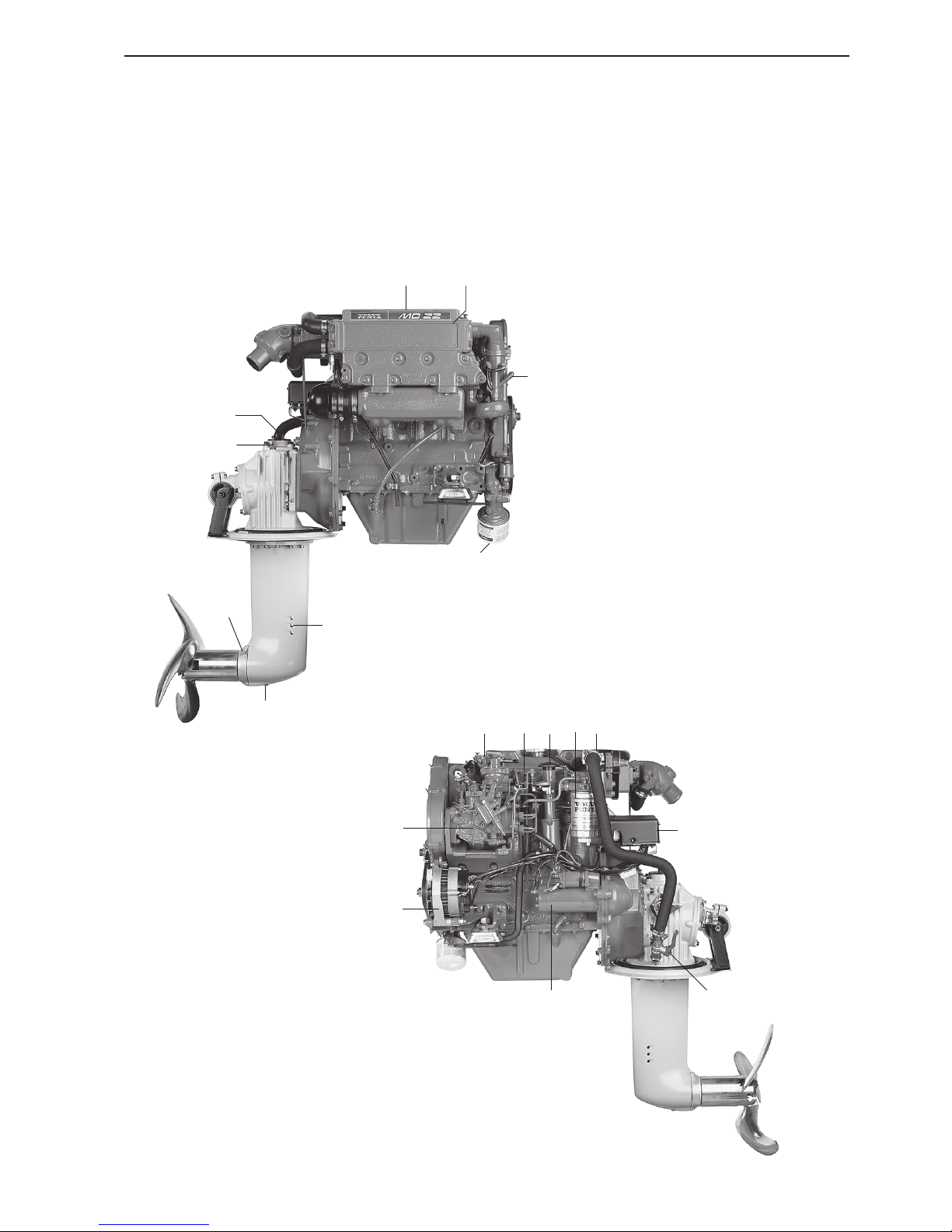
MD22L/120S
1. Coolant filler
2. Heat exchanger
3. Pipe for oil scavenging pump
4. Oil filter
5. Starter motor
6. Generator
7. Injection pump
8. Fuel feed pump
9. Dipstick (engine)
10. Oil filler cap (engine)
11. Fuel filter
12. Sea water pump
13. Central electronics unit
14. Topping up oil (drive)
15. Oil dipstick (drive)
16. Seacock
17. Sacrificial anode
18. Draining oil (drive)
19. Seawater intake
13
8
9 10
11
12
7
6
516
MD22L/120S
General information
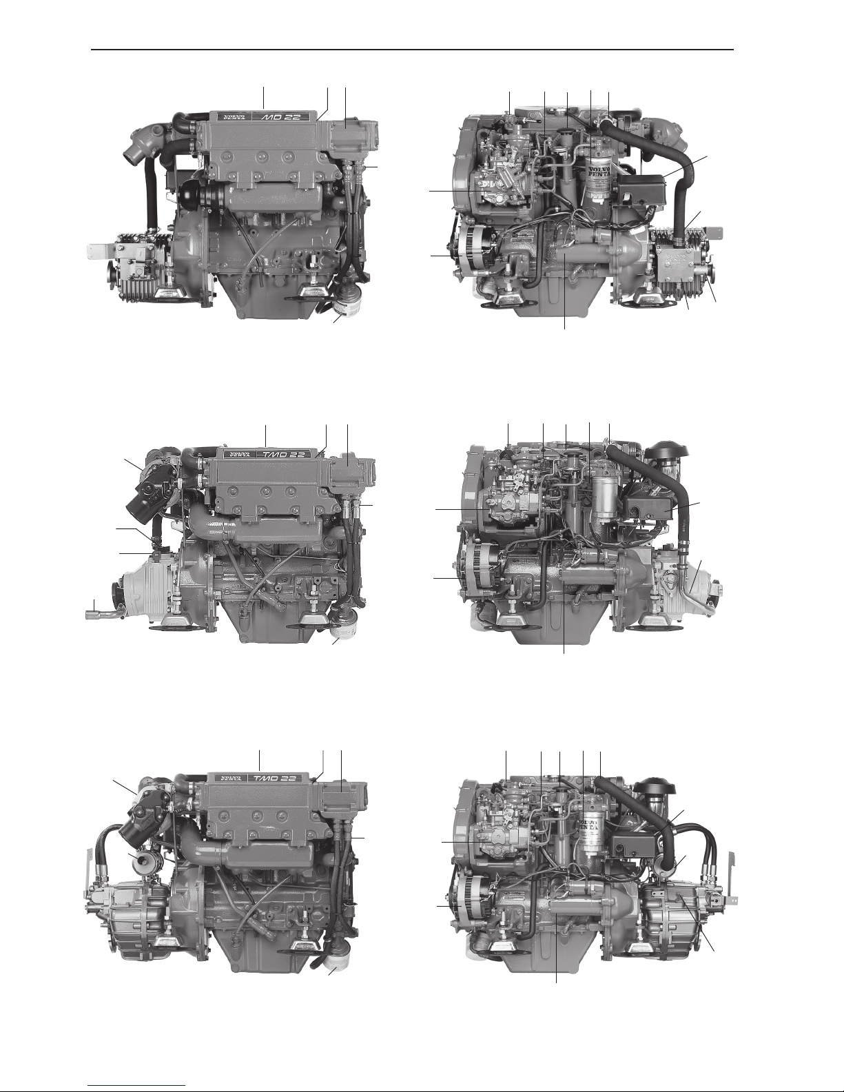
Engine presentation
Page 16
14
2
3
4
5
7
MD22P/MS25
18, 19
21
17
11 12
13 14
15
10
9
8
20
17
11
12
13 14
15
10
9
8
20
TMD22/MS2
2
3
4
5
7
TMD22P/HS25
1
21
18, 19
17
11
12
13
14
15
10
9
8
20
21
19
18
2
3
4
5
7
1
General information
Page 17
15
5
6
7
1 2 3 4
25
26
27
24
11 12 13 14 15 16 17
10
18
19
9
21
22
8
23
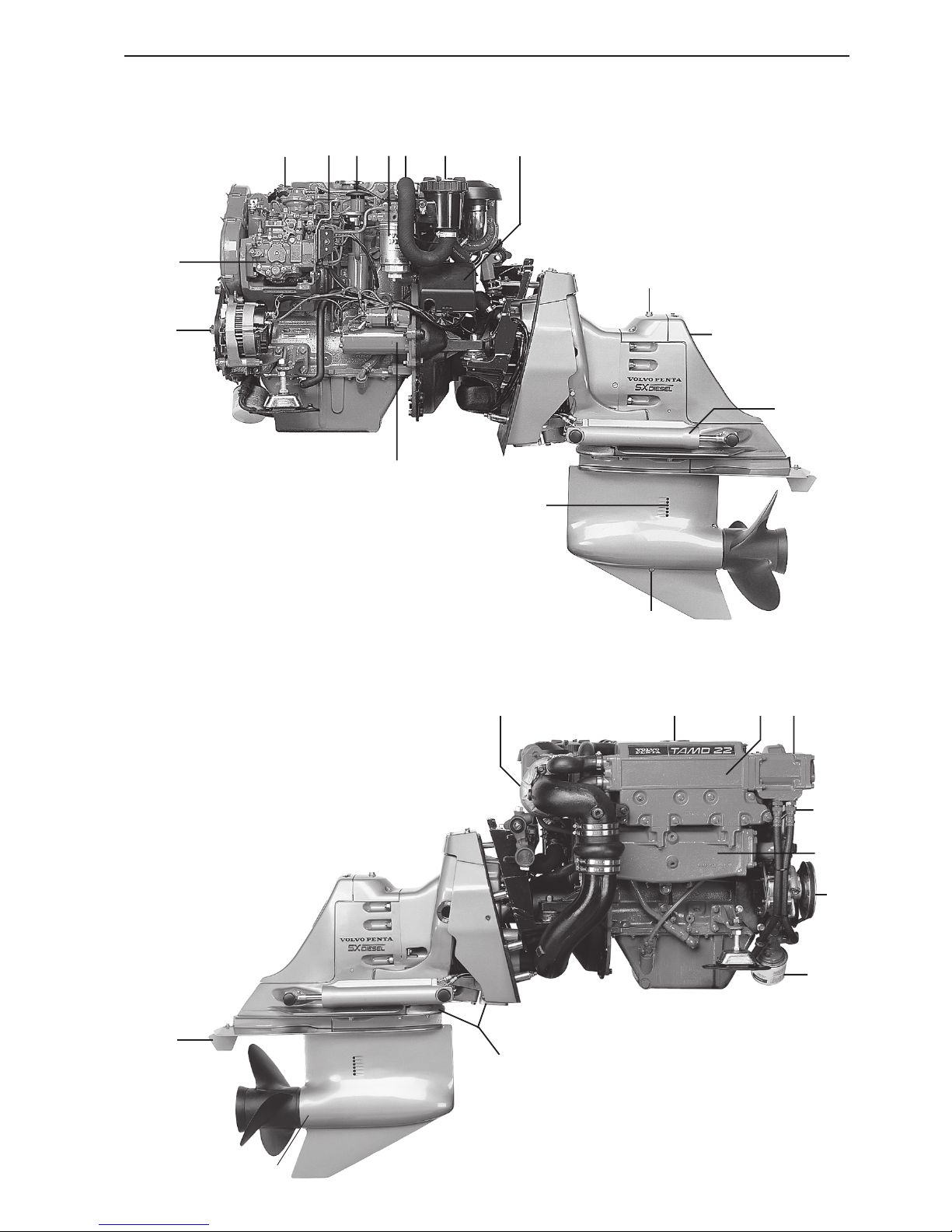
TAMD22P/SX
1. Turbo (TMD, TAMD)
2. Coolant filler
3. Heat exchanger
4. Oil cooler
5. Pipe for oil scavenging pump
6. Charge air cooler (CAC) (TAMD)
7. Oil filter
8. Starter motor
9. Generator
10. Injection pump
11. Fuel feed pump
12. Dipstick (engine)
13. Oil filler cap (engine)
14. Fuel filter
15. Sea water pump
16. Seawater filter (SX)
17. Central electronics unit
18. Oil dipstick (reverse gear / SX)
19. Oil filler (reverse gear / SX)
20. Oil cooler (reverse gear)
21. Seawater intake
22. Trim cylinder (SX)
23. Draining oil (SX)
24. Servo pump (SX)
25. Sacrificial anode (SX)
26. Sacrificial anode (SX)
27. Trim fin (SX)
General information
Page 18

16
Cylinder head
Cylinder head
General
The carbon deposits in a diesel engine are small
and therefore the number of operational hours do
not give an indication of when it is time to recondition a cylinder head. The factors which determine
when reconditioning is necessary are ease of starting the engine and the all round performance.
The cylinder head is made of aluminum and the
head is drilled together with the camshaft cover in
order to localize the camshaft bearing. The camshaft cams lie directly above the valves and affect
them using the valve lifters, which are mounted on
top of the valves. The shims are installed between
the valve lifters and the top of the valves so that adjustment is possible.
The cylinder head has two valves per cylinder.
Each valve is installed with a single valve spring.
The valves move in cast valve guides which are
pressed into the cylinder head and can be replaced.
Both the valve stems are equipped with oil seals
which pass over the top of the valve guides.
Valve seat inserts are installed in the cylinder head
for both the inlet and exhaust valves.
Page 19
17
Cylinder head
Repair Instructions
Camshaft cover, replacement
(12A-01)
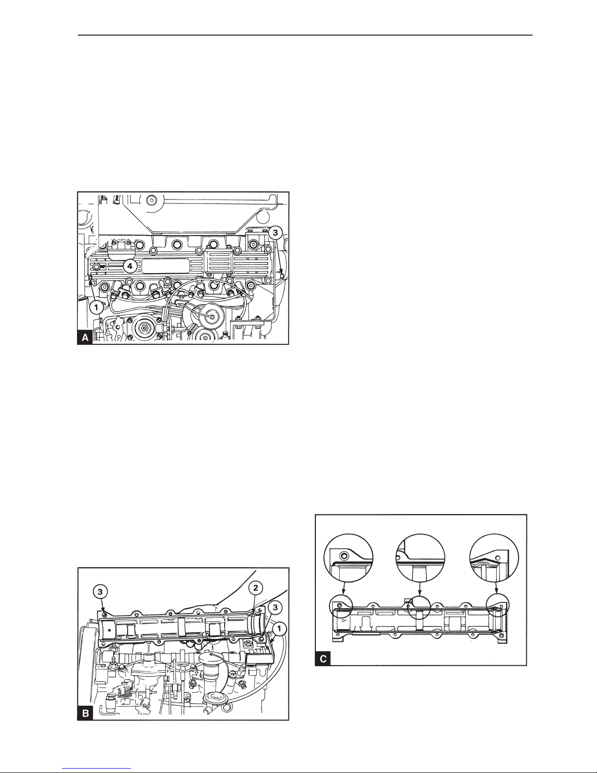
Special tools: 885025
1
Remove the screws securing the camshaft cover
front flange to the timing cover (A1).
Remove the screw installed through the seawater
pump drive housing in the rear flange of the cover
(A3). If it is too cramped to remove the cover, remove the mounting bracket for the sea water pump.
2
Remove the screw over the adjustment hole at the
top of the front end of the camshaft cover (A4). Turn
the crankshaft until the adjustment hole in the front
of the camshaft front bearing journal corresponds
with the hole in the cover. This makes it easier to
dismantle the fuel supply pump and the camshaft
cover.
3
Remove the engine lifting brackets. If nothing is
driven from the rear end of the camshaft, remove
the rear cover and install the camshaft lock 885025
(B1). This ensures that the camshaft does not tilt
when the camshaft cover is removed.
4
Remove the fuel supply pump, operation 19A-03.
5
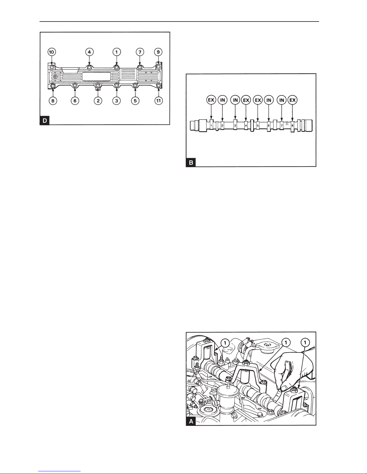
Remove the camshaft cover screws evenly in reverse order to that given in illustration D. Remove
the screws and the cover (B). Ensure that the thrust
washer (B2) remains in place in the cover.
6
Check the cover and the camshaft thrust washer for
wear and other damage. If the cover is damaged or
worn a new cylinder head assembly, because the
holes for the camshaft bearing journals are machined with the cylinder head and the camshaft cover installed to each other.
7
Check that the guide sleeves (B3) and thrust washer (B2) is correctly installed. Ensure that the camshaft front and rear stuffing boxes still remain in the
correct position against the collar in the cylinder
head and that are not crooked.
8
Page 20
18
Check that the groove in the camshaft cover and
the mating surfaces on the cylinder head and cover
are clean. Apply a 2mm bead of silicon in the outer
groove of the cover, but leave the inner groove
empty as illustrated in illustration (C). Install the
cover directly after the sealant has been applied. Install the mounting screws with the longer screws in
each end of the cover. Tighten the screws in stages
in order to hold the cover parallel to the cylinder
head when it is tightened. Finally tighten the screws
to 22 Nm in the order displayed in the illustration
(D).
9
Install and tighten the screw securing the seawater
pump drive housing to the camshaft cover. If the installation bracket for the seawater pump has been
removed, align the bracket before tightening it see
operation 20A-08.
10
Install and tighten the screws securing the timing
cover to the camshaft cover. Install the cover to
the timing cover if required.
11
Ensure that the adjustment hole in the front of the
camshaft front bearing journal corresponds with the
hole in the camshaft cover. Install the fuel supply
pump, operation 19A-03. Install the screw in the adjusting hole in the camshaft cover. Install the engine
lifting brackets.
Valve clearance, check
(12A-02)
Special tools: 885025, 885024
The valve clearance is measured between the camshaft and the upper side of the valve lifter (A). With
a cold engine the correct valve clearance 0.25-0.35
mm for the inlet valves and 0.35 –0.45 mm for the
exhaust valves. See B for the position for the inlet
and exhaust cams.
Cam no.1 is at the camshaft pulley end.
1
Disconnect the battery.
2
Remove the camshaft cover, operations 12A-01.
Dismantle the seawater pump, operation 20A-06
and install the camshaft lock 885025 before the
cover is removed.
3
Cylinder head
Page 21

19
Cylinder head
Valve clearance, adjustment
(12A–03)
Special tools: 885024, 885025, 885037
If when checking valve clearance, operation 12A02, it appears that the adjustment is necessary carry on as follows:
1
Turn the crankshaft until the adjustment hole in the
camshaft front bearing journal is at “12 o’clock”.
Install the adjustment drift 885037 through the rear
plate or through the flywheel cover using the flywheel adjustment hole.
2
Remove the cap of the timing cover, operation
15A-01.
3
Remove the mounting screws for the camshaft pulley and the mounting screw for the pulley hub.
4
Install two screws (M6 x 50) to hold the fuel injection pump pulley.
5
Remove the timing belt, the camshaft pulley and the
pulley hub see section 15.
6
Remove the seawater pump, operation 20A-06 and
the mounting bracket for the pump, operation 20A-
08.
7
Remove the camshaft mountings and remove the
camshaft (12A.07/A). Remove the stuffing boxes
from the camshaft.
Install the camshaft mountings 885024 (A1) to hold
the camshaft and mount the mountings with the relevant mounting screws for the cover. It is vital to
move the rear camshaft stuffing box on the camshaft to secure sufficient clearance between the
rear mounting and the stuffing box. Ensure that the
sprung pads are correctly installed on the camshaft
bearing journals and tighten the mounting screws
for the mountings evenly.
4
Turn the crankshaft until the tips of cams 1 and 3
are both near their highest point. Use a feeler gauge
with a bent blade to measure the valve clearance
for valves 1 and 3. Make a note of the clearance.
5
Repeat point 4 for valves 2 and 5, 6 and 8 and 4 and
7.
6
Adjustment is only necessary if play lies outside the
0.20-0.40mm for the inlets valve or 0.30-0.50 for the
exhaust valves. If adjustment is necessary see operation 12A-03.
7
When the clearance is correct remove the mountings for the camshaft bearing journals and install
the camshaft cover, operation 12A-01.
8
Connect the battery.
Page 22
20
Cylinder head
8
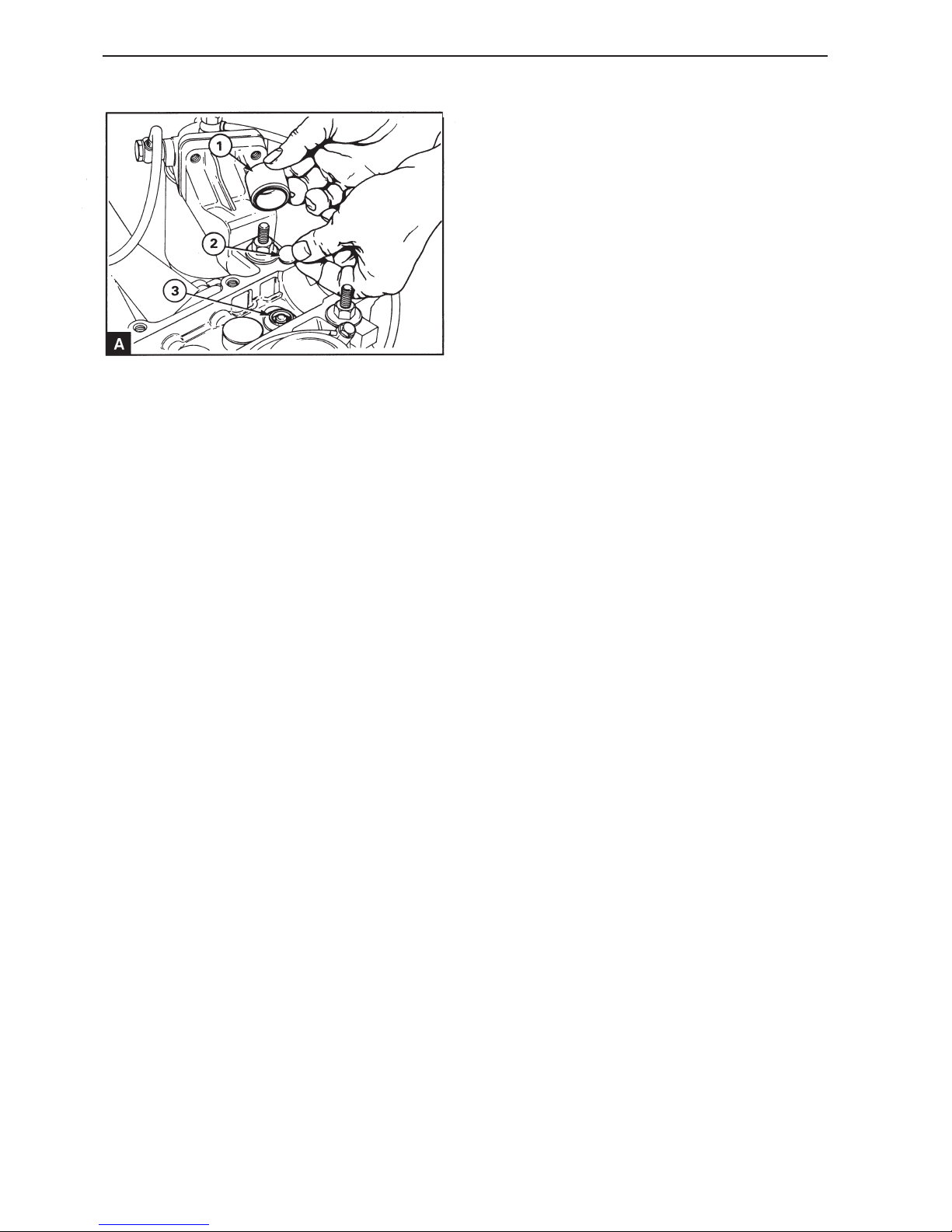
Adjust each valve lifter in the following order: Remove the valve lifter (A1) and remove the shim
(A2), located on top of the valve spring washer
(A3). Calculate the adjustment for each valve lifter
using the notes from operation 12A-02 Measure the
thickness of the existing shim. If the clearance
must be increased insert a thinner shim of the thickness required. If the clearance must be decreased
insert a thicker shim. Use the average clearance of
0.30 mm for the inlet 0.40 mm for the exhaust
valves when calculating. Lubricate the valve lifter
and insert it in the hole. Repeat the operation for
each valve lifter requiring adjustment.
9
When all the shims requiring changing have been
replaced, install the camshaft in position and install
the temporary camshaft pulley hub. Remove the adjustment drift and the locking tool from the flywheel.
Turn the crankshaft a quarter turn clockwise. Install
the camshaft mountings and check that the valve
clearance is correct, operation 12A-02.
10
If the play is correct, remove the camshaft pulley
hub and the camshaft mountings. Turn the crankshaft a quarter turn counter-clockwise. Install the
adjustment drift and the locking tool on the flywheel.
Lubricate the valve lifters and the camshaft bearing
journals and cams.
11
Install the camshaft cover, operations 12A-01.
12
Install the new front and rear stuffing box on the
camshaft, operations 12A-04 and 12A-05.
13
Install the camshaft pulley and the timing belt, see
section 15. Remove the locking drifts from the fuel
injection pump pulley and adjust the belt tension,
operation 15A-03.
14
Remove the adjustment drift. Check the fuel injection pump adjustment, operations 17A-03.
15
Install the cap of the timing cover, operation
15A-01.
16
Install the screw in the adjustment hole in the camshaft cover. Install the back plate for the camshaft
cover.
Install the bracket for the seawater pump, operation
21A-08 and the seawater pump, operation 20A-06.
17
Turn the crankshaft two revolutions to ensure that
there is nothing preventing free movement.
Page 23
21
Cylinder head
Front sealing ring,
replacement (12A-04)
Special tools: 885026, 885018, 885037
1
Disconnect the battery
2
Remove the screw from the adjustment hole on the
top of the front end of the camshaft cover (12A.03/
A4). Turn the crankshaft until the adjustment hole in
the front of the camshaft front bearing journal corresponds with the hole in the cover.
3
Install the adjustment drifts 885037 on the camshaft
and flywheel.
4
Remove the cap of the timing cover, operation 15A-
01.
5
Remove the camshaft pulley, operation 15A-06.
6
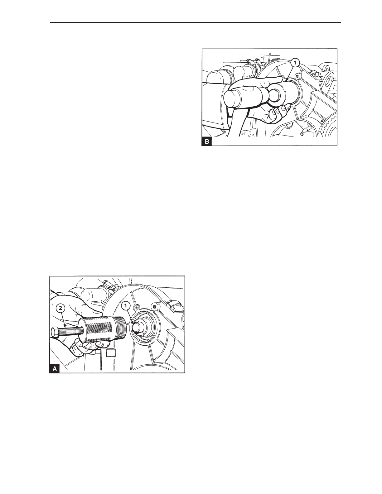
Install the plug from the tool 885026 (A1) in the front
end of the camshaft. Unscrew the center screw
(A2) sufficiently to ensure that it does not reach the
plug and insert the main tool into the stuffing box.
Turn the tool clockwise to ensure that the it is secure in the stuffing box and tighten the center screw
against the plug to remove the stuffing box.
7
Ensure that the stuffing box and the camshaft are
clean and undamaged. Lubricate the new stuffing
box with fresh engine oil and insert it into position
with the seal lip inwards. Use installation tool
885026 (B1) and a hammer with a soft face to drive
the stuffing box into the correct position.
8
Install the camshaft pulley and the timing belt, see
section 15. Remove the locking drifts from the fuel
injection pump pulley and adjust the timing belt tension, operation 15A-03.
9
Check the fuel injection pump adjustment, operations 17A-03.
10
Remove the adjustment drifts and turn the crankshaft two revolutions to ensure that there is nothing
preventing free movement.
11
Install the screw in the adjustment hole in the camshaft cover. Connect the battery.
Page 24
22
Cylinder head
Rear sealing ring, replacement
(12A-05)
Special tools: 885019, 885020, 885038
1
Remove the seawater pump and the drive housing
and remove the drive adapter from the camshaft
end, see section 20.
2
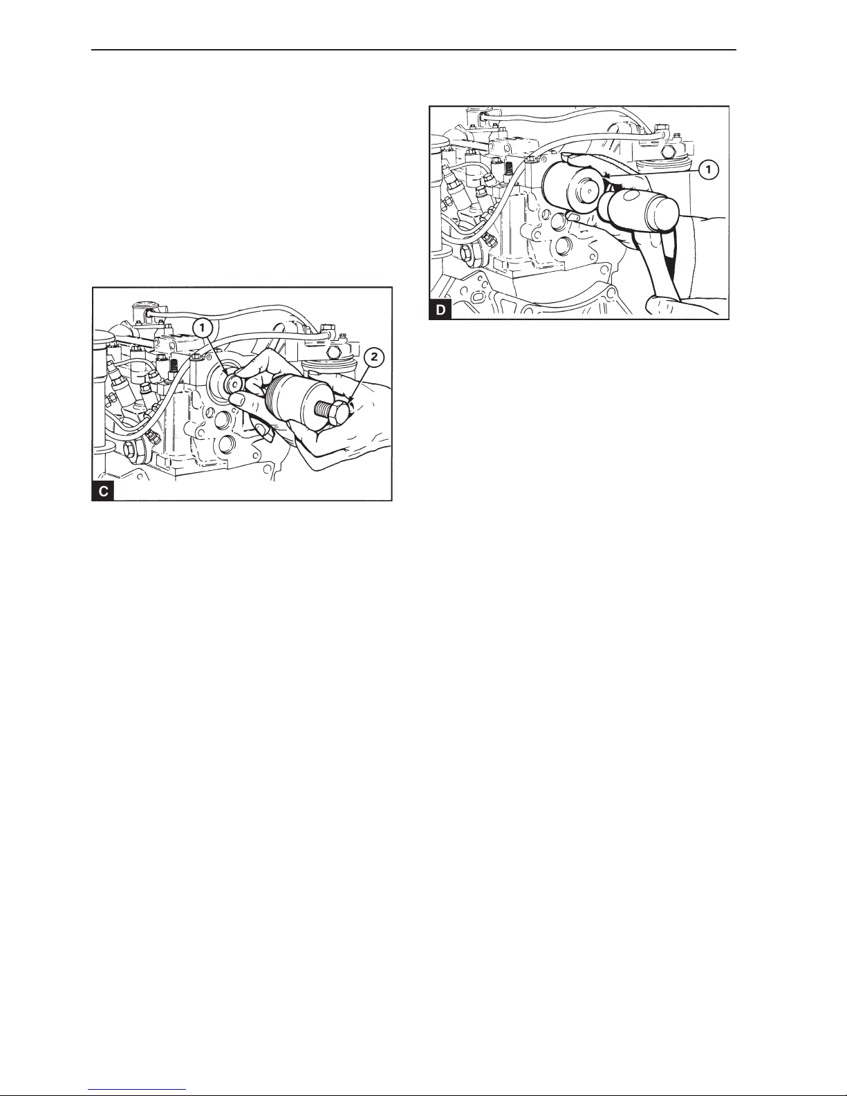
Install the plug from the tool 885019 (C1) in the rear
end of the camshaft.
3
Unscrew the center screw (C2) sufficiently to ensure that it does not reach the plug and insert the
main tool into the stuffing box. Turn the tool clockwise to ensure that the it is secure in the stuffing
box and tighten the center screw against the plug to
remove the stuffing box.
4
Ensure that the stuffing box and the camshaft are
clean and undamaged. Lubricate the new stuffing
box with fresh engine oil and insert it into position
with the seal lip inwards. Use installation tool
885020 (D1) and a hammer with a soft face to drive
the stuffing box into the correct position.
5
Install the seawater pump drive housing with the
hole correctly aligned, operation 20A-08. Install the
seawater pump drive adapter and tighten the domed
screws to 9 Nm. Install the seawater pump, operation 20A-06.
Page 25
23
Cylinder head
Camshaft, replacement
(12A-06)
Special tools: 885037
1
Disconnect the battery
2
Remove the screw from the adjustment hole on the
top of the front end of the camshaft cover (12A.03/
A4). Turn the crankshaft until the adjustment hole in
the front of the camshaft front bearing journal corresponds with the hole in the cover.
3
Install the adjustment drifts 885037 on the camshaft
and flywheel.
4
Remove the cap of the timing cover, operation 15A-
01.
5
Remove the camshaft pulley, operation 15A-06.
6
Remove the camshaft cover, operations 12A-01.
7
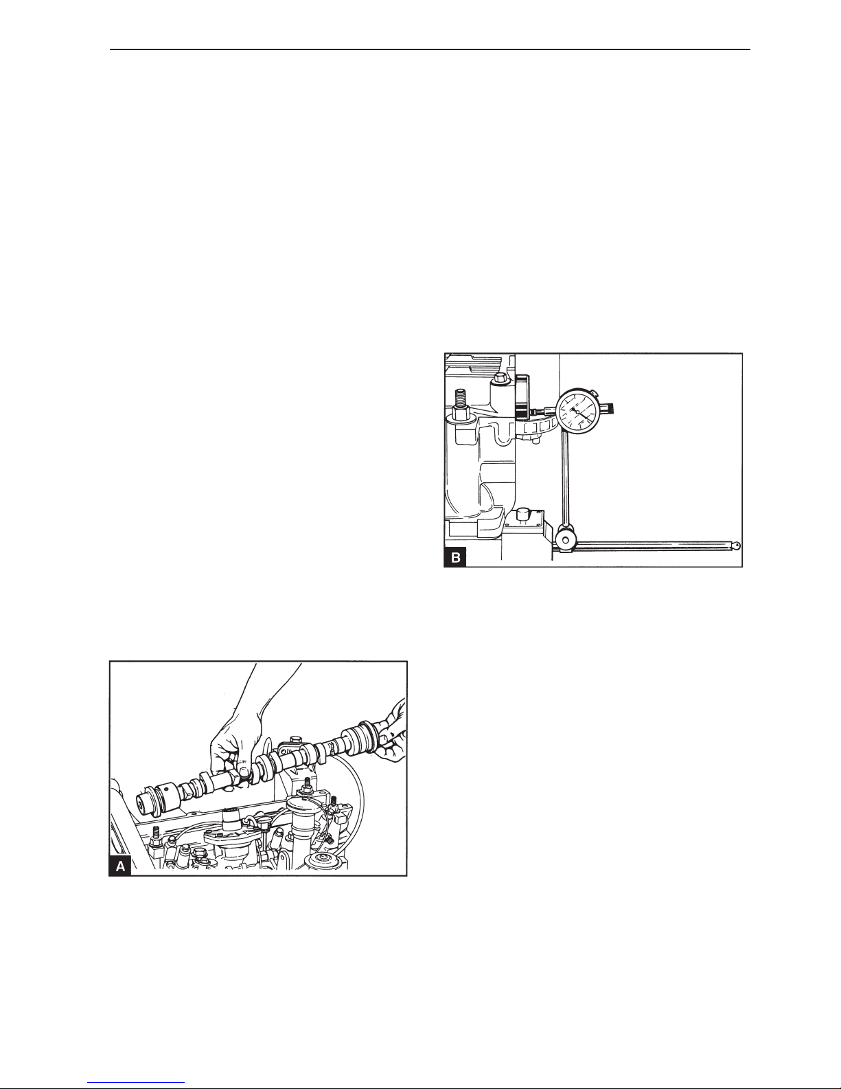
Remove the camshaft (A) and remove the camshaft
sealing rings.
8
Check the camshaft for wear and damage and replace it if required.
9
Ensure that the camshaft is clean and lubricated
with fresh engine oil. Install the camshaft in position
and check the valve clearance if necessary, see
operation 12A-02.
10
Install the camshaft cover, operations 12A-01.
11
Check the camshaft axial clearance with a dial indicator (B). For tolerances see Workshop Manual
“Technical data”.
12
Install the camshaft sealing rings, operations 12A04 and 12A-05.
13
Install the rear camshaft cover.
Install the seawater pump, section 20.
14
Install the camshaft pulley and the timing belt and
adjust the belt tension, section 15.
Page 26

24
Cylinder head
15
Check the fuel injection pump adjustment, operations 17A-03.
16
Install the cap of the timing cover, operation 15A-
01. Install the screw in the adjustment hole on top
of the camshaft cover front section.
17
Check that all adjustment drifts are removed.
Turn the crankshaft two revolutions to ensure that
there is nothing preventing free movement.
18
Connect the battery.
Cylinder head assembly,
replacement (12A-07)
Special tools: 885037
1
Disconnect the battery.
2
Drain the cooling system.
3
Detach the engine coolant hose from the thermostat
housing. If necessary remove the by-pass hose at
the bottom of the thermostat housing.
4
Detach all wiring at the cylinder head and thermostat housing.
5
Detach the intake manifold and exhaust pipe.
6
If the cylinder head is being dismantled:
Remove the intake manifold and the heat exchanger
/ manifold / coolant tank assembly, operation 20A-
12.
7
Detach the fuel supply pump.
8
Detach the fuel filter and remove it from the bracket.
9
Remove the delivery lines from the injectors and
from the fuel pump (FP) – do not bend the pipes.
When a pipe nut is removed at the pump, hold the
output terminal from the pump with a wrench so that
the connection does not move. Install the protective
cover over the open terminals at the injectors and
the pump.
Page 27
25
Cylinder head
10
Remove the injectors, operation 19A-02 and the
glow plugs, operation 22C-01 to prevent any possible damage to the tips.
11
Remove the screw from the adjustment hole on the
top of the front end of the camshaft cover 12A.03/
A4. Turn the crankshaft until the adjustment hole in
the front of the camshaft front bearing journal corresponds with the hole in the cover.
12
Install the adjusting drift on the flywheel.
13
Remove the cap of the timing cover, operation 15A01 and remove the camshaft pulley, operation 15A-
06.
14
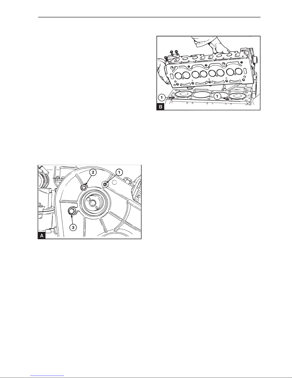
Remove the mounting screw which is installed
through the camshaft cover into the timing cover
(A1).
Remove the screw securing the timing cover to the
cylinder head (A3).
15
Unscrew the screws for the cylinder head evenly in
reverse order compared to the illustration 12A.09/A.
Remove the screws and dismantle the cylinder
head (B), ensure that the camshaft does not come
into contact with the timing cover. Place the cylinder head on even surface that will not damage the
cylinder head surface.
16
Check the upper side of each screw head for punch
marks. If there are four punch marks on the screw
heads it means that the screws have been post
tightened four times and cannot be reused. Check
the screws for deformation using a straight edged
ruler held along the screw. If there is a visible decrease in shaft diameter or in the threaded section,
which has not been not been threaded into the cylinder head, the screw must be discarded.
17
Remove the cylinder head gasket.
18
Clean the underside of the cylinder head and the
surface of the cylinder block. Ensure that there is
no debris in the cylinder bores.
19
Ensure that the 1st and 4th pistons are at top dead
center and that the adjustment drifts are installed
through the back plate or through the flywheel cover
in the flywheel adjustment hole.
Page 28
26
Cylinder head
Ensure that the adjustment drifts are installed
through the camshaft cover into the adjustment hole
in the camshaft. Install the cylinder head in position
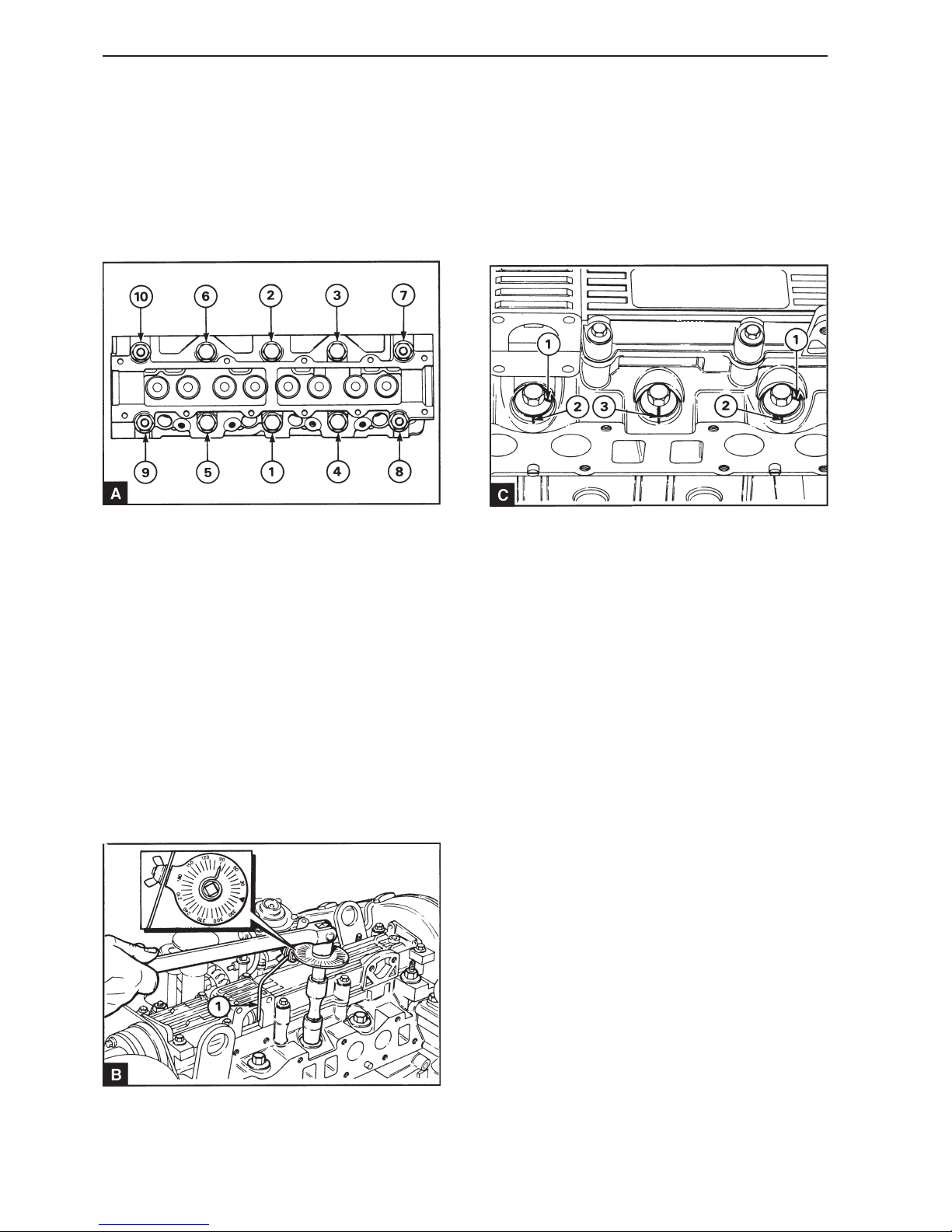
over the guide sleeves. Screw in the cylinder head
screws with the long screws located at the cylinder
head ends. Tighten the screws evenly in the order
shown in illustration (A) to a torque of 50 Nm. Tighten the screws again, in the same order to a torque
of 100 Nm. Finally tighten the screws a further
quarter turn (90°) in the same order. Install the tool
between the socket and the handle. Apply the stop
against a suitably extended part of the cylinder head
to prevent the protractor turning clockwise. Turn the
indicator so that it corresponds with the 90° marking
on the protractor. Tighten the screw until the indicator points to zero.
If no tool is available make a suitable marking on
each screw flange (C1). Make other markings on
the cylinder head (C2) with 90° clockwise offset in
relation to the markings on the screws. Tighten
each screw in the correct order until the markings
on the screw match the markings on the cylinder
head (C3). The screws do not need to be post tightened with the engine at operating temperature or after a certain period of operation.
If the original screws have been reinstalled, mark
the top of each screw with a punch mark to indicate
that the screws have been tightened operationally.
A maximum of four punch marks is permitted.
22
Install the heat exchanger / manifold / coolant tank
assembly, operation 20A-10 and install the intake
manifold.
23
Connect the air filter and the exhaust pipe.
24
Install the screws securing the timing cover to the
cylinder head (12A.08/A1) and to the camshaft cover (12A.03/A1).
25
Install the camshaft pulley and the timing belt and
check the belt tension, see section 15.
20
Ensure that the two guide sleeves (12A.08/B1) is in
position in the cylinder block surface and install the
cylinder head gasket without sealing compound.
The gasket can only be installed in one position
over the guide sleeves.
21
Page 29

27
Cylinder head
35
Fill the engine coolant system. See operation 20A-
02.
36
Connect the battery.
37
Bleed the fuel injection system, operation 19A-08.
38
Start the engine and check for leaks.
26
Check the fuel injection pump adjustment, operations 17A-03 and remove the adjustment drifts. Turn
the crankshaft two revolutions to ensure that there
is nothing preventing free movement.
27
Install the glow plugs, operation 22C-01.
28
Install the injectors, operation 19A-02.
29
Install the fuel delivery lines and tighten the connector nuts to 18 Nm. Ensure that a separate wrench is
used to prevent movement in the outgoing connections from the fuel injection pump.
30
Install the fuel filter and the low pressure fuel lines
between the fuel injection pump and the fuel filter.
31
Install the fuel supply pump if necessary, operation
19A-03. Connect the wiring to the fuel supply pump.
32
Install the cap of the timing cover, operation 15A-
01.
33
Connect the coolant by-pass hose and the outlet
hose for the coolant.
Connect the sea water pipes to the heat exchanger
and to the seawater pump.
34
Connect the wiring to the cylinder head and to the
thermostat housing.
Page 30
28
Cylinder head
Valves and valve springs,
replacement (12A-08)
Special tools: 885023
1
Remove the cylinder head, operations 12A-07.
2
Remove the seawater pump, operation 20A-06.
3
Remove the camshaft cover, operations 12A-01.
4
Remove the valve lifters and shims and place each
valve lifter and shim together in a numbered place,
so that they can be returned to their original positions.
5
Clean the underside of the cylinder head and check
how deep the valve crowns are under the cylinder
head surface, see operation 12A-09.
6
Make a suitable marking on the valve crowns so
that the valves can be installed in their original positions if they are to be reused.
7
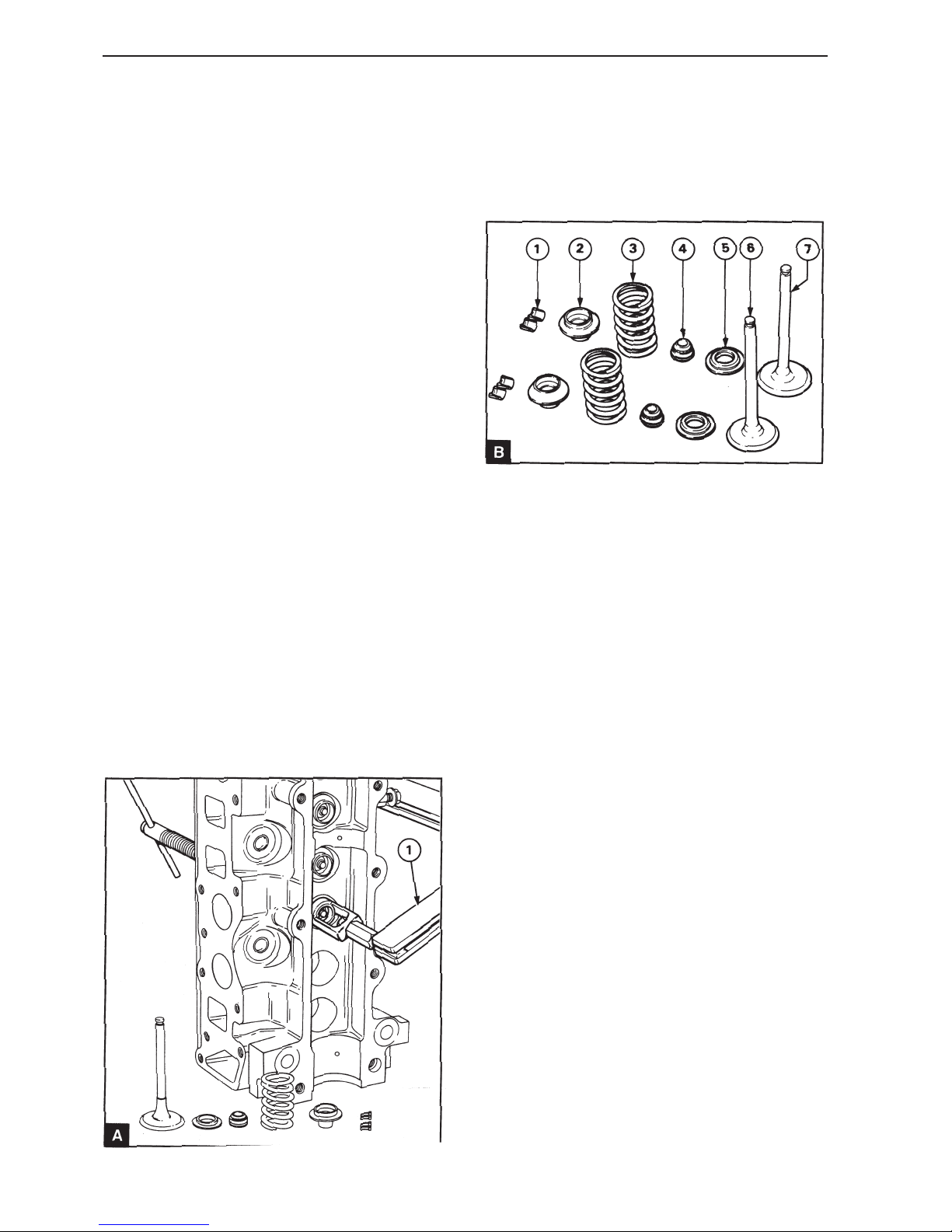
Press the valve springs together with the valve
spring tensioners (A1). Ensure that the spring is
pressed straight downwards so that the valve stem
is not damaged. Remove the valve cotter (B1).
8
Take the load off the valve spring tensioner and remove the valve spring washer (B2), valve spring
(B3), valve stem seal (B4) and the spring seat
washer (B5). Remove the exhaust valve (B6) or the
inlet valve (B7).
9
Repeat points 7 and 8 for the other valves.
10
Ensure that the components are clean.
The components in the valve assembly, as shown
in illustration B.
11
Lubricate the valve stems with fresh engine oil and
install the valves B6 / B7 in their respective guides.
Ensure that the valve crown depth, see operation
12A-09.
12
Install the spring seat washers (B5). Install the new
valve stem seals (B4) on the valve guides. Install
the valve springs (B3) and the valve spring washers
(B2).
Page 31
29
Cylinder head
13
Use the valve spring tensioner to compress the
valve spring and the install the valve cotter (B1).
Ensure that the valve spring is pressed straight
down so that the valve stem is not damaged.
14
Lubricate the shims and valve lifters. Install each
shim above the valve spring washer for each valve
and install the valve lifter above each shim.
15
Install the camshaft in position and check valve
clearance according to operation 12A-02. Adjust
valve clearance as necessary.
16
Install the camshaft and the camshaft cover, operation 12A-02.
17
Install the seawater pump, operation 20A-06.
18
Install the cylinder head, operation 12A-07.
Valves and valve springs,
inspection (12A-09)
1
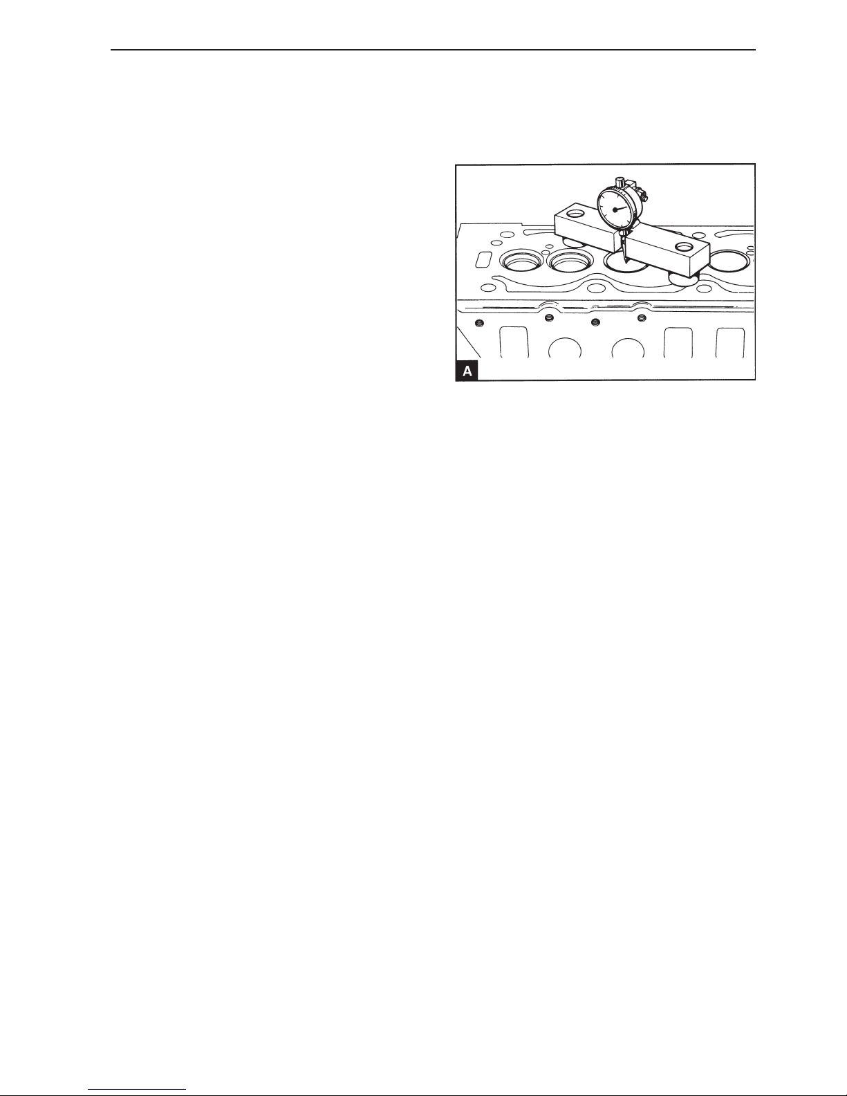
Check the depth of the valve crowns under the cylinder head surface, before removing the valve
springs. Ensure that the valve crowns and the cylinder head underside are clean. Install the valve
depth gauge on the cylinder head surface and zero
the gauge. Install the valve depth gauge carefully in
position above each valve crown (A) and note the
value. The parameter values for valve crown depth
are given in the Workshop Manual “Technical Data”.
If a valve is deeper than the maximum value, check
the valve depth using a new valve. If the valve
depth is still outside the permitted value, a new
valve seat can be installed, operation 12A-14.
2
Check for the valves for cracks. Check the valve
stems for wear and correct alignment in the valve
guides.
3
Check that the valves mating surfaces to the seats
are not badly burnt or damaged. Valves with damaged sealing surfaces can be reground in a special
machine. Lightly damaged valves can be lapped in
to the valve seats. When new valves are installed
the valve depth must be checked.
4
Check that the spring loading is the correct at the
installed length, see Workshop Manual “Technical
data”.
Install the new valve springs at every complete engine reconditioning.
Page 32
30
Cylinder head
Valve guides, inspection
(12A-10)
Special tools: 885021, 885022
Check the valve guides for wear. The maximum
play between the valve stem and the hole in the
guide is 0.13 mm. If the clearance is greater when a
new valve is installed, a new valve guide must be
installed.
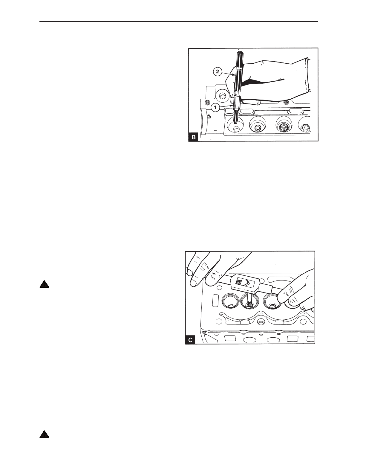
6
Install the guide B1 on the thin end of the tool
885021 (B2) with the bevel turned to the thin end of
the tool (B). Insert the bevelled end of the guide into
position in the cylinder head and press in the guide
until the tool end comes into contact with the flat
plate. Check that the guide protrudes 10 mm above
the mating surface for the valve spring.
7
Allow the cylinder head to cool.
8
Ream the hole for the new guide using reamer
885022 (C).
Valve guides, replacement
(12A-11)
1
Ensure that the surface of the cylinder head and the
storage surface in a suitable press are clean.
2
Heat the whole cylinder head slowly and evenly to
approximately 100°C and lay the head with the surface downwards. Ensure that the surface is not
damaged during handling.
WARNING! Use suitable gloves as protection
against the hot metal.
3
Install the thin end of tool 885021 in the guide and
press it out. Repeat the procedure if several guides
need to be replaced.
4
Clean the valve guide position and ensure that it is
not damaged.
5
Heat the whole cylinder head slowly and evenly to
approximately 100°C. Lay the head in the press with
the surface downward with a flat surface located under the valve opening. Ensure that the head surface
is not damaged during handling.
WARNING! Use suitable gloves as protection
against the hot metal.
Page 33
31
Cylinder head
Cylinder head, inspection
(12A-12)
1
Remove the cylinder head assembly, operations
12A-07.
2
Remove the thermostat housing.
3
Remove the seawater pump, operation 20A-06.
4
Remove the camshaft cover, operation 12A-01 and
the camshaft.
Remove the valve lifters and shims and place each
valve lifter and shim together in a numbered place,
so that they can be returned to their original positions.
5
Check the cylinder head for signs of gas or coolant
leakage.
6
Remove the valve springs and valves, operation
12A-08.
7
Clean the cylinder head surface. Clean the coolant
and lubrication channels. The water mantle can be
cleaned with a special solvent which must be used
according to the manufacturers instructions.
8
Check the cylinder head for leakage at the pressure
specified in the Workshop Manual “Technical Data”.
9
When the cylinder head is completely clean, it
should be checked for cracks. Carefully check the
areas around the valve seats and the holes for injector nozzles.
10
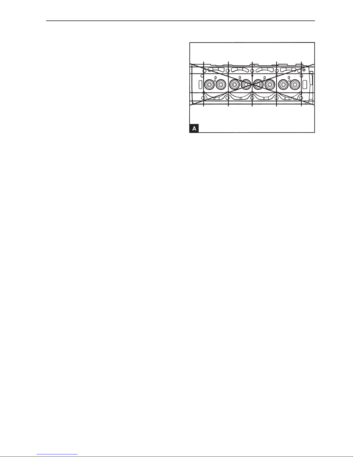
Use a straight edged ruler and a feeler gauge to
check the latitudinal, longitudinal and diagonal flatness of the bottom surface of the cylinder head (A).
If deformation is greater than 0.10 mm the bottom
surface can be machined. Remove the minimum
amount of material and check that the cylinder head
height will not be less than 119.85 mm after the cylinder head has been treated.
NOTE! After the cylinder head has been machined
the valve seats must be corrected to give the correct valve depth. It is recommended to use the minimum value to allow for wear later.
11
Check the valve seats for damage and wear.
12
Before carrying out any work on the valve seats,
check that the valve guides are not worn, see
Workshop Manual “Technical Data”. If valve guide
wear is above the parameter values the valve
guides must be replaced, operation 12A-11.
13
If the damage is mild the valve and valve seat can
be lapped in. When the valve seats are lapped keep
the sealing area as thin as possible and ensure that
all lapping paste used on the valve and seat is removed.
Page 34
32
Cylinder head
Valve seat, grinding (12A-13)
1
If the valve guide is worn it should be replaced, operation 12A-11.
2
Install the locating pin in the valve guide and tighten
it.
3
14
Valve seats with more serious damage can be corrected using a milling tool, operation 12A-13 or a
new valve seats can be installed, operation 12A-14.
15
Install the valve springs and valves, operation 12A-
08.
16
Install the camshaft cover, operation 12A-01 and
the camshaft. Install the valve lifters and shims in
their correct positions. Install the camshaft in position and check the valve clearance, operation 12A02 and adjust as necessary, operation 12A-03.
17
Install the seawater pump, operation 20A-06.
18
Install the thermostat housing.
19
Install the cylinder head assembly, operation 12A-
07.
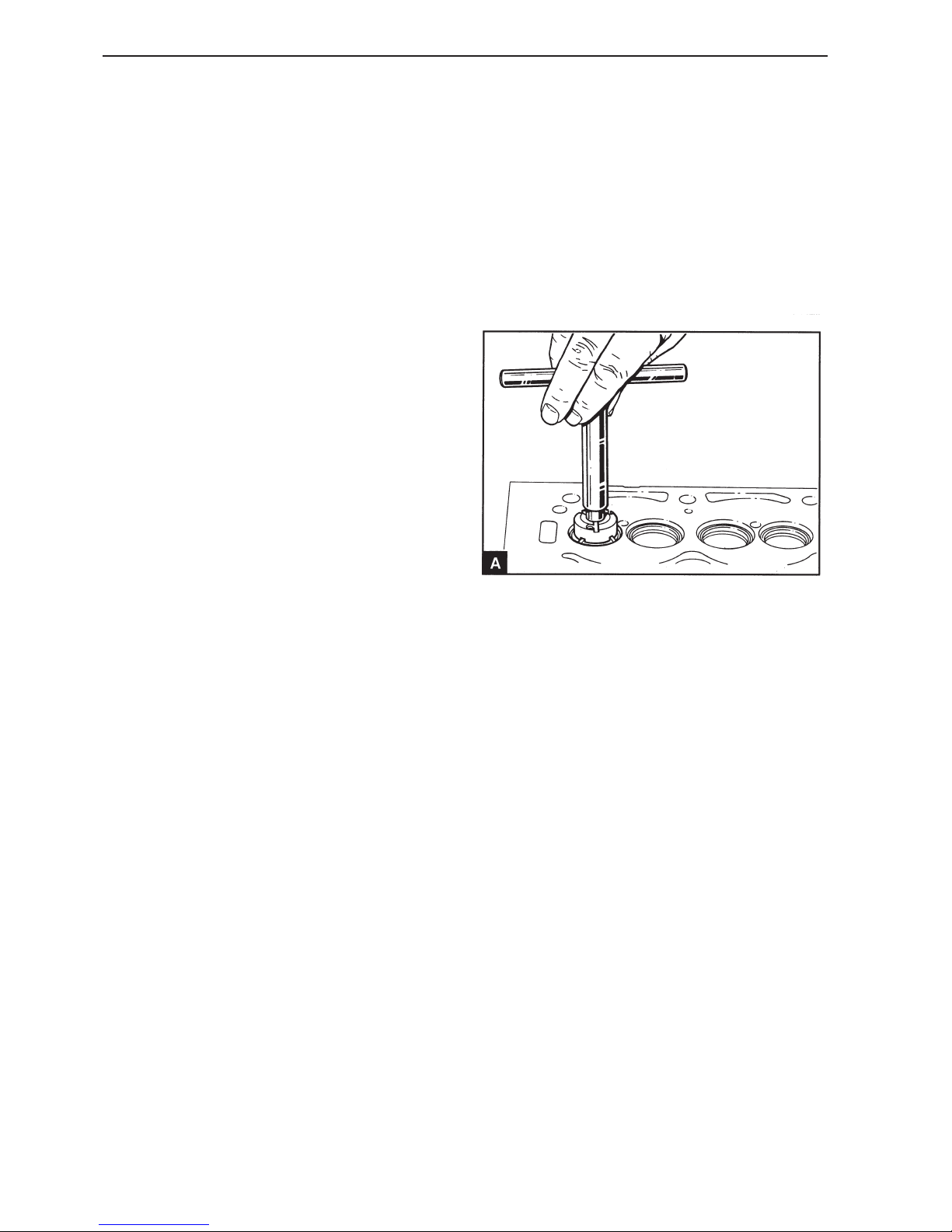
Install the mill on the locating pin with 46° side
against the valve seat and install the handle (A). Do
not let the mill head fall down towards the seat, this
can damage the blade.
4
Turn the mill carefully clockwise. Only remove as
much material as is necessary to achieve a seal.
Keep the sealing area as thin as possible.
5
Remove the mill and the locating pin when a satisfactory sealing area has been achieved. Remove all
the work remnants from the area around the valve
seat and valve opening.
6
Install the valve and lightly lap the valve and seat.
7
Check that valve depth lies within the permitted parameters, see Workshop Manual “Technical Data”.
If a valve seat has become too damaged or worn it
must be replaced, operation 12A-14.
Page 35

33
Cylinder head
Valve seat, replacement
(12A-14)
1
Install a new valve guide, operation 12A-11.
2
Work a small segment from the inside of one side of
the valve seat to a depth of 8.25 mm from the surface of the cylinder head. Split the seat at the thinnest point and remove it from the cylinder block.
Clean the seat position and check that there are no
cracks.
3
The valve seat must be installed with the cylinder
head hot and the seat cold. Heat the whole cylinder
head slowly and evenly to approximately 100°C and
if possible cool the seat with liquid nitrogen to –
35°C. If liquid nitrogen is not accessible, cool the
seat down as much as possible in a freezer. Install
the seat with exterior bevel turned to the inside of
the head. Ensure that the bottom of the seat has
good contact with the bottom of the position in the
cylinder head.
WARNING! Use suitable gloves as protection
against the hot metal and the cold seat.
4
Mill the valve seat, 12A-13 and carefully lap the
valve and valve seat. Ensure that the valve crown
depth under the cylinder head surface is within the
production parameters, see Workshop Manual
“Technical Data”. Work as closely to the minimum
value to allow for later valve seat wear.
Page 36
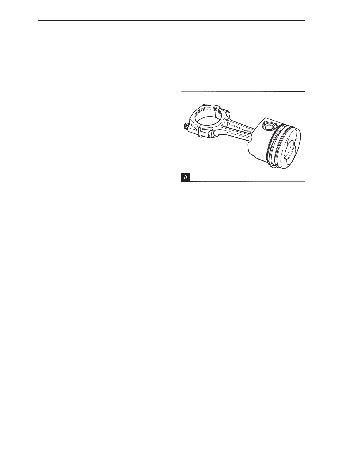
34
Piston and connecting rod
General
The combustion chamber on the upper side of the
piston has a special ”swirl lip” to provide an effective fuel – air mixture. On the high effects the upper
side of the piston is turned to ensure clearance between the valves and the glow plugs.
The pistons have two compression rings and one oil
scavenger ring. The groove for the top ring is in a
hard metal insert to minimize the groove wear. Axial
guidance of the floating piston pins occurs using
snap rings. There is a steel insert in the piston mantle to check the pistons dilation.
The connecting rods are H section forged steel. The
bearing caps are located to the connecting rods using tight connecting rod screws with.
Page 37
35
Repair Instructions
Big ends, replacement
(13A-01)
1
Drain engine oil.
2
Remove the oil pan, operation 18A-03
3
Remove the oil screen and extractor pipe, operation
18A-04.
4
Turn the crankshaft until the relevant connecting rod
is in its lowest position.
5
Unscrew the nuts and remove the bearing cap.
6
Remove the lower bearing shell from the bearing
cap and put it together with the cap.
7
Install a plastic or rubber tube of suitable length on
each respective connecting rod screw to protect the
big end. Carefully slide the connecting rod up the
cylinder, enough so that the upper bearing shell can
be accessed. Remove the bearing shell from the
connecting rod. Place the big end shells with the respective bearing caps.
8
Clean the bearing surfaces on the connecting rods
and big end journals.
9
Clean the bearing shells and lubricate the bearing
surfaces and big end journals. Install the upper
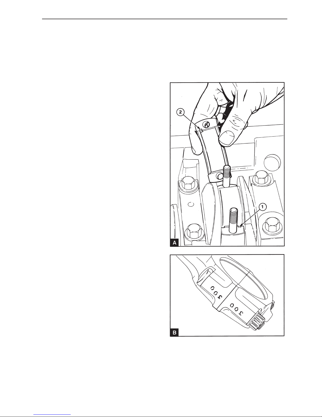
bearing shell for the connecting rod with the locking
lug well inserted in the cut out (A1). Install the connecting rod to the big end journal. Ensure that the
marking on the connecting rod (B) lies in the same
direction as the other connecting rods.
Page 38
36
Piston and connecting rod
10
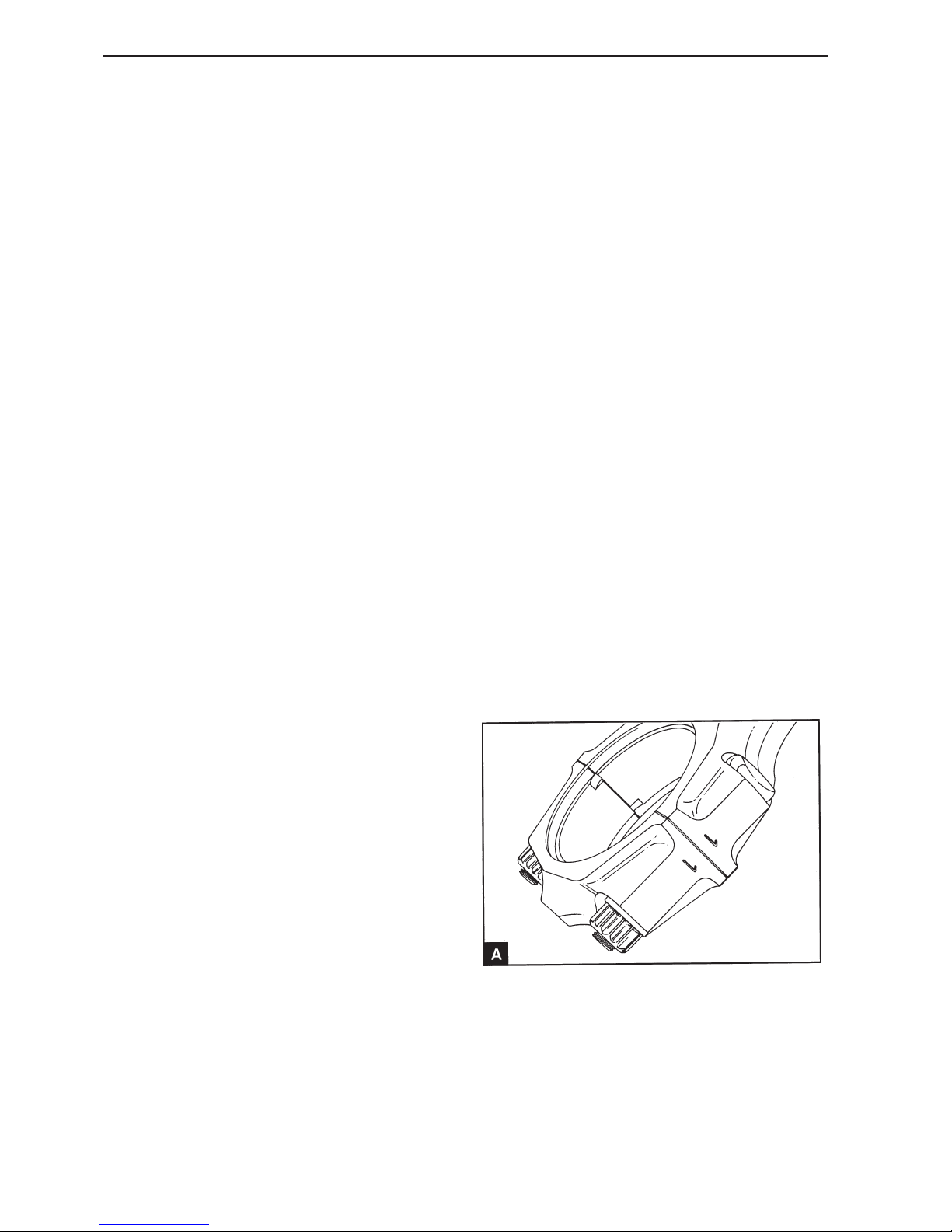
Clean, lubricate and install the lower bearing shell in
the cap. Ensure that the guide lug is slid well into
the cut out (A2). Remove the protective hosing from
the connecting rod screws and check that the
screws have not been damaged. Install the connecting rod cap. Ensure that the unit number on the
cap is the same as on the connecting rod (B) and
that both unit numbers are turned in the same direction.
11
Install new nuts for the connecting rod screws.
Tighten them evenly and in stages to 47 Nm.
12
Check that the crankshaft can be freely turned.
13
Install the oil screen and extractor pipe, operation
18A-04.
14
Install the oil pan, operations 18A-03 and fill it to the
correct level with approved engine oil.
Piston and connecting rod assembly, replacement (13A-03)
1
Drain the engine oil and the engine coolant system.
2
Remove the cylinder head assembly, operations
12A-07.
3
Turn the crankshaft until the pistons are at the
same height in the cylinder bores. Place a suitable
clean rag over the piston to fill the cylinder bores.
Remove all soot from the upper section of the cylinder bore with a coarse emery cloth. The emery
cloth should be dampened with oil in order to retain
the impurities. Polish the cleaned surface with a
fine emery cloth. Clean the cylinder bore and remove the rag.
4
Remove the oil pan, operation 18A-03.
5
Remove the oil screen and extractor pipe if required, operation 18A-04.
6
Check that all the connecting rods and the caps are
marked with the correct cylinder number (A). If they
are not marked, mark them from 1 to 4 with the
number 1 at the timing belt cover end.
Big ends, inspection (13A-02)
Check the bearing shells and the big end journals
for wear and other damage.
Page 39
37
Piston and connecting rod
7
Remove the big end bearing cap and the connecting
rod bearing caps, operation 13A-01. Keep the bearing shells with the relevant caps so that they can be
returned to their original positions.
8
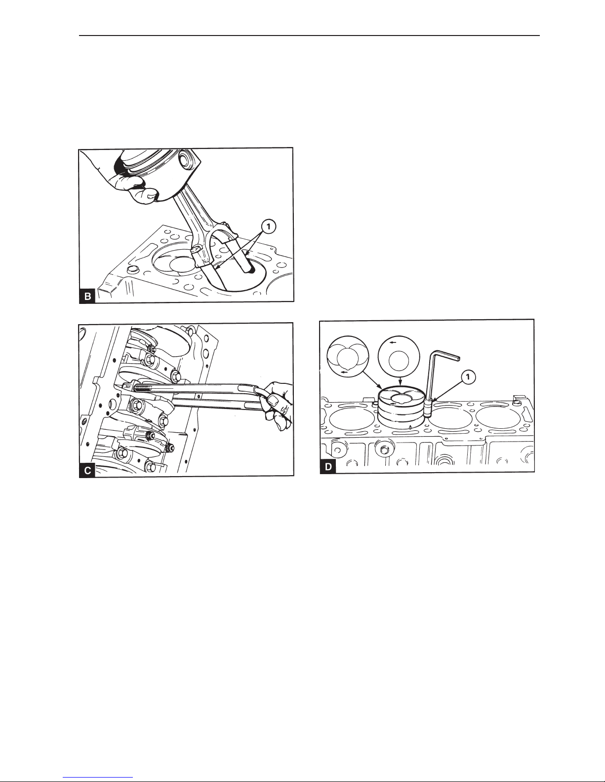
Install rubber or plastic protective tubes on the connecting rod screws (B1). Slide the piston and the
connecting rod upwards in the cylinder bore A suitable tool for this job can be made from a (U) shaped
pipe and two pieces of plastic hose (C).
9
Check the big end journal for damage.
10
Ensure that the piston, cylinder bore, big end journal and connecting rod big end are clean. Lubricate
the piston and cylinder bore with fresh engine oil.
11
Turn the crankshaft until the relevant connecting rod
is in its lowest position. Lubricate the big end journal with engine oil.
12
Install a plastic or rubber tube of suitable length on
each respective connecting rod screw to protect the
big end. Install the upper bearing shell on the connecting rod. Ensure that the locking lug is slid well
into the cut out (A1). Lubricate the bearing with engine oil.
13
Ensure that the piston ring gaps are offset by 120°
and press the rings together with a piston ring compressor (D1). Ensure that the protruberances
pressed against one edge of the tool are bent downwards.
14
Install the piston unit in the correct cylinder bore.
When the piston is installed the arrow on the upper
side of the piston (D) must point towards the front
end of the engine (timing cover end). In this position
the combustion chamber on the top of the piston is
turned towards the side of the engine on which the
injection pump is installed. There is also a front end
marking on the underside and on the connecting rod
and these markings must be on the same side, see
13A.07/B.
Page 40
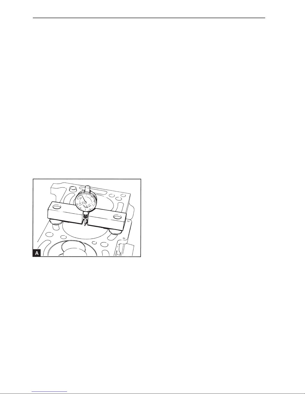
38
Piston and connecting rod
15
Slide the piston and connecting rod through the cylinder bore and down to the big end journal. Turn the
connecting rod so that the arrow on the upper side
of the piston points towards the front end of the engine.
16
Remove the protective tubes from the connecting
rod screws. Clean the connecting rod bearing cap
and the lower bearing shell. Install the bearing shell
in the cap with the locking lug slid well into the cut
out. Lubricate the bearing with engine oil. Install the
cap and ensure that the unit number is the same as
on the connecting rod and that the numbers are on
the same side. Install new nuts for the connecting
rod screws. Tighten them evenly and in stages to
47 Nm.
17
Check that the crankshaft can be freely turned.
18
Check the piston height above the cylinder block
surface with the piston height measuring tool (A).
Place the measuring tool on a flat surface and zero
the measuring scale. Turn the crankshaft until the
piston is approximately at top dead center. Locate
the measuring tool over the cylinder bore with the
dial gauge measuring point in contact with the piston. Turn the crankshaft so that the piston moves to
its highest position and note the value. The correct
value for the piston height is given in the Workshop
manual “Technical data”. If a new service piston of
a lower height class has been installed, see operation 13A-05, the piston height may be 0.10 mm lower than the lowest parameter. The piston may not be
higher than the upper limit. Metal must not be removed from the upper side of the piston.
19
Install the oil screen and extractor pipe if required,
operation 18A-04.
20
Install the oil pan, operation 18A-03.
21
Install the cylinder head assembly, operation 12A-
07.
22
Fill the oil pan to the correct level with approved engine oil.
23
Fill the engine coolant system.
Page 41
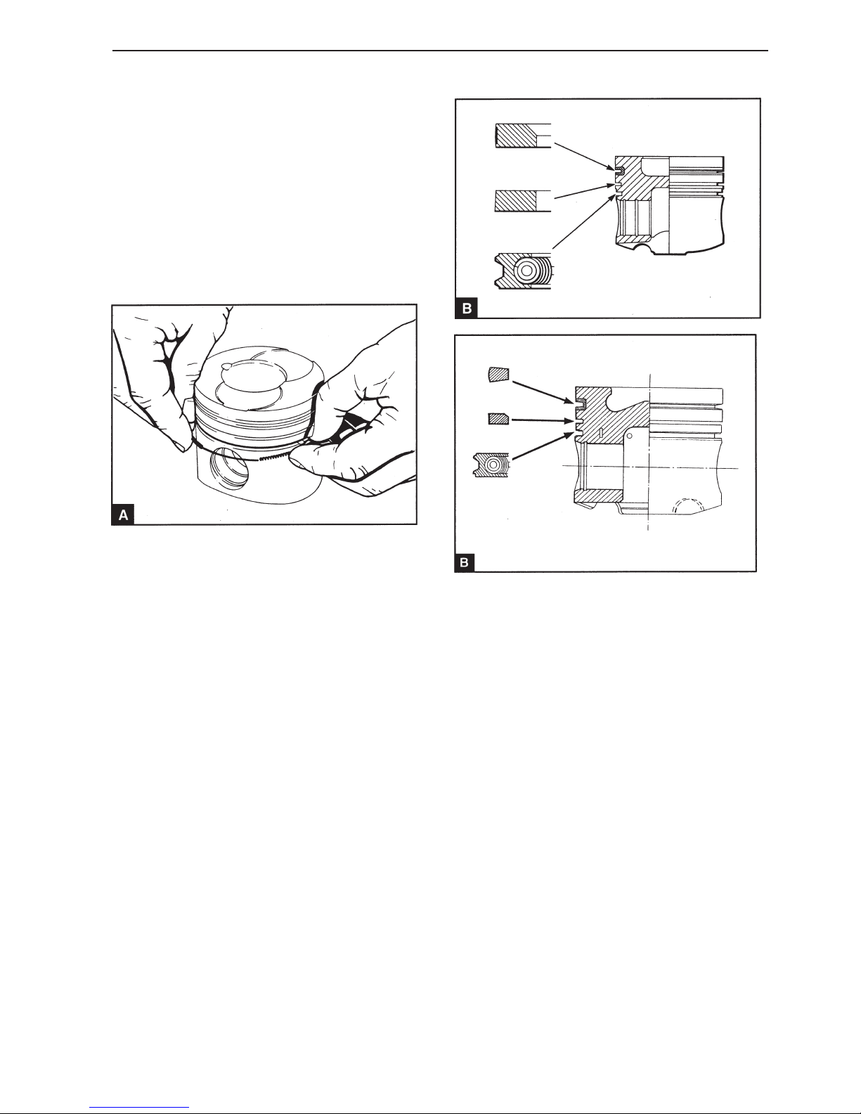
39
Piston and connecting rod
Piston rings, replacement
(13A-04)
Remove the piston rings with an appropriate piston
ring pliers Separate the ring gap just sufficiently
that the ring ends do not damage the piston. Keep
the rings together with the relevant piston.
Install the piston rings with an appropriate piston
ring pliers Separate the ring gap just sufficiently
that the ring ends do not damage the piston.
1
3
Insert the expander ring for the oil scraper ring in
the lower piston ring groove with the catch through
both end of the rings (A). Install the oil scraper ring
over the spring (B). Ensure that the ring gap is located with a 180° offset to the catch.
2
Install the cast iron rings with the conical surface in
the second piston ring groove with the word “TOP”
or the manufacturers symbol towards the top. The
new piston rings have a green identification mark.
This must lie to the left of the ring gap when the ring
is installed and the piston is raised.
Install the “barrel face” ring with the molybdenum insert in the upper piston ring groove (TMD22P,
TAMD22 Keystone ring). The word “TOP”, the manufacturers mark or the internal milling must face the
top of the piston. The new piston rings have a red
identification mark. This must lie to the left of the
ring gap when the ring is installed and the piston is
raised.
4
Ensure that the ring gaps are offset 120° internally.
MD22L, MD22, TMD22
TMD22P, TAMD22
Page 42
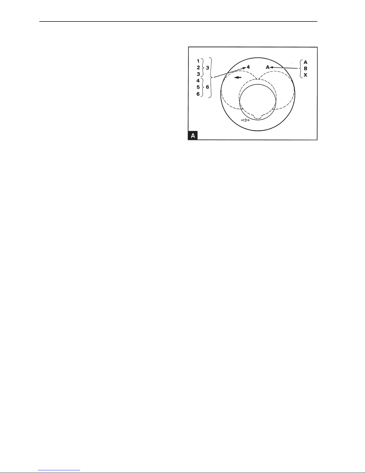
40
Piston and connecting rod
Piston and connecting rod,
assembly / dismantling
(13A-05)
1
Remove the piston rings, operation 13A-04.
2
Remove the snap rings holding the piston pins in
position.
3
Make a temporary marking on the piston to display
the cylinder number as given on the connecting rod.
Make the marking on the piston on the same side
as the marking on the connecting rod big end to ensure that they are correctly installed together.
4
Press out the piston bolt by hand. If the piston bolt
is fixed, heat the piston to 40-50°C to allow the piston bolt to be removed.
5
Clean the hole in the piston pin bushing and lubricate with fresh engine oil.
6
Install a new snap ring in one of the piston bolt positions on the piston.
7
If the original piston is used, ensure that it is installed on the correct connecting rod and the original cylinder. If a new piston is installed, ensure that
it is the correct height class. There are six different
height classes in production. The classes are designated with numbers which are stamped on the top of
piston (A). Number 1 is the highest piston and
number 6 the lowest. Only classes 3 and 6 are
available for service purposes. Class 3 must be
used if the original piston has the markings 1, 2 or
3. Class 6 must be used if the original piston has
the markings 4, 5 or 6. Two different diameter
classes ”A” and ”B” are also in production. Only piston A with the smaller diameter is available for the
standard cylinder diameter for service purposes. A
class (X) piston is accessible for cylinders which
have been bored out by 0.50 mm oversize in connection with service repairs. The diameter classes
are stamped on a machined plate in the right upper
rear edge of the cylinder block (16A-04/C). If a cylinder bore has been bored out to oversize in a service repair, the letter for the original class should be
stamped with an (X).
Page 43

41
Piston and connecting rod
8
Place the connecting rod with piston upside down.
The locating lug (B2) on the connecting rod must be
on the same side as the arrow (B1) on the underside of the piston.
9
Lubricate the piston bolt position in the piston with
fresh engine oil and slide in the piston bolt towards
the snap ring. If the piston bolt has difficult to insert,
heat the piston to 40°-50°C before the piston bolt is
installed.
10
Install a new snap ring in the other piston bolt position on the piston. Ensure that it goes into the
groove correctly.
11
Install the piston rings, operation 13A-04.
Piston and piston rings,
inspection (13A-06)
1
Check the piston for wear and damage.
2
Check that the piston rings can move freely in its
groove and that no ring is broken.
3
Remove the piston rings, operation 13A-04. Clean
the piston ring and the piston ring grooves.
4
Install the new piston rings in the piston ring groove
and check the ring groove wear using the feeler
gauge (A). Compare the piston ring play in the
groove to the values that apply to new components
in the Workshop Manual “Technical Data”. Replace
the cylinder if necessary.
5
Check that all the soot has been removed from the
upper section of the cylinder bore. Install the piston
rings in the upper section of the cylinder bore and
measure the ring gap with a feeler gauge (B). The
expander ring must be installed on the oil scraper
ring when the ring gap is measured. The ring gap for
the new components is given in the Workshop manual “Technical data”.
Page 44
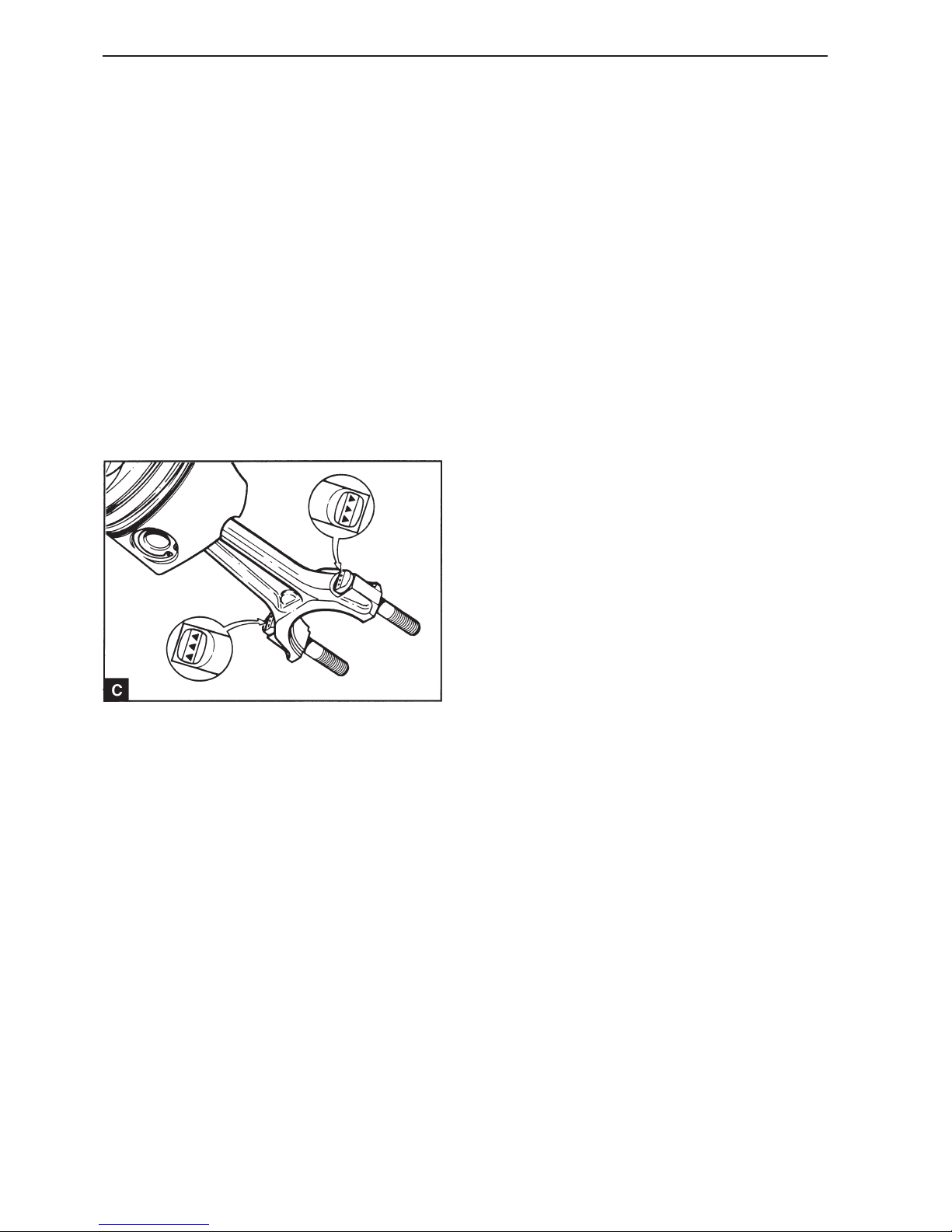
42
Piston and connecting rod
Connecting rod, inspection
(13A-07)
1
Check the connecting rods for deformation, see
Workshop Manual “Technical Data”.
2
Check the connecting rod bushing for wear or other
damage and replace it as necessary.
3
Check the piston bolt alignment in the connector rod
bushing and check the piston bolt for wear, see
Workshop Manual “Technical Data”.
4
Check the condition of the connecting rod screws. If
the thread is sealed or if there are signs of stretching, the screw must be removed from the connecting rod and replaced. The new screw must be installed with the locating arrows (or recognition
marks) on the screw head turned to the outside of
the connecting rod big end (C). Ensure that the
screw head has good contact with the connecting
rod.
Connecting rod b ushing,
replacement
(13A-08)
1
Press out the old bushing with an appropriate drift.
2
Clean the bearing recess in the connecting rod and
remove any sharp edges.
3
Press in the new bushing. Ensure that the lubrication in the bushing is on the same side and is pointed towards the hole in the top of the connecting rod.
4
Ream the bushing in order to obtain the correct
clearance between the piston bolt and the bushing,
see Workshop Manual “Technical Data”.
Page 45

43
Crankshaft assembly
General
The crankshaft is made of ductile cast iron. It has
integral balancing weights and five main bearing
journals.
The axial play is controlled by two sectioned thrust
washers on each side of the central main bearing.
The main bearings have a steel plate mantel and a
surface bearing of tin-aluminum. The main bearing
cap is made of ductile cast iron.
The front and rear stuffing boxes have lip seals
made of Viton and oil return grooves on the inside of
the lip. The front stuffing box is installed on the front
side of the lubricating oil pump. On most engines
the rear stuffing box is located directly in the flywheel cover or the back plate.
The crankshaft front end has two separate keygrooves. The rear keygroove is for the lubricating
oil pump, which is installed around the crankhaft.
The front keygroove is for the belt pulley, which
drives the timing belt.
The crankshaft pulley is fastened to the belt pulley
with four domed screws and fastened to the crankshaft with a center screw.
A vibration damper is integrated into the pulley.
Page 46
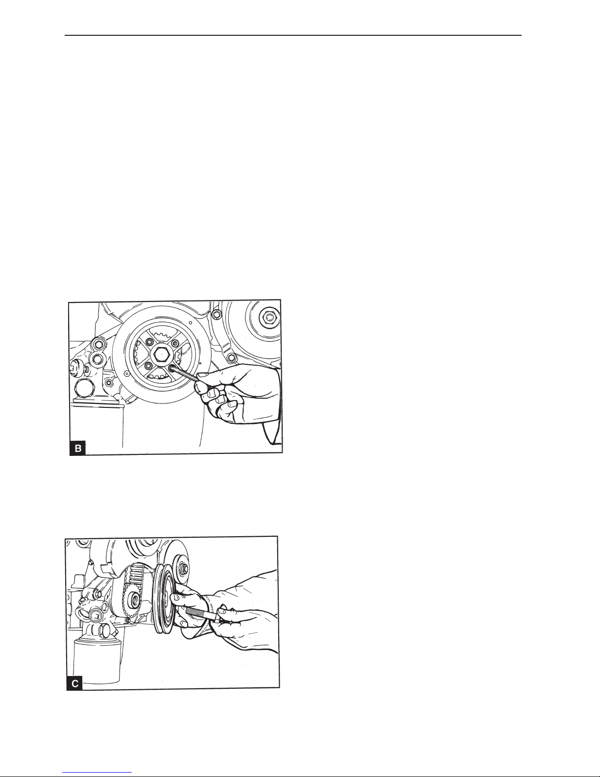
44
Repair Instructions
Crankshaft pulley, replacement
(14A-01)
1
Disconnect the battery.
2
Remove the generator (GEN) drive belt, operation
22A-02.
3
Remove the starter motor, operation 22B-01.
4
Unscrew and remove the four mounting screws (B)
which secures the pulley to the belt pulley.
5
Slacken off the pulley center screw and remove the
pulley (C). Use a large screwdriver or similar tool
as a counterhold at the flywheel ring gear.
NOTE! The belt pulley is locked to the front end of
the crankshaft using Loctite 648 and can only be removed using a puller.
6
Clean the components and check them for damage.
Replace damaged components as necessary.
7
Install the pulley to the belt drive and tighten and
finger tighten the four mounting screws.
8
Install the center screw (black), P/N 3581332 and
tighten to 180 Nm. Use a large screwdriver or similar tool as a counterhold at the flywheel ring gear.
9
Tighten the four mounting screws to:
Flanged screw 22 Nm
Domed screws 36 Nm
10
Remove the counterhold and install the starter motor, operation 22B-01.
11
Remove the generator (GEN) drive belt, operation
22A-01.
12
Connect the battery.
Page 47
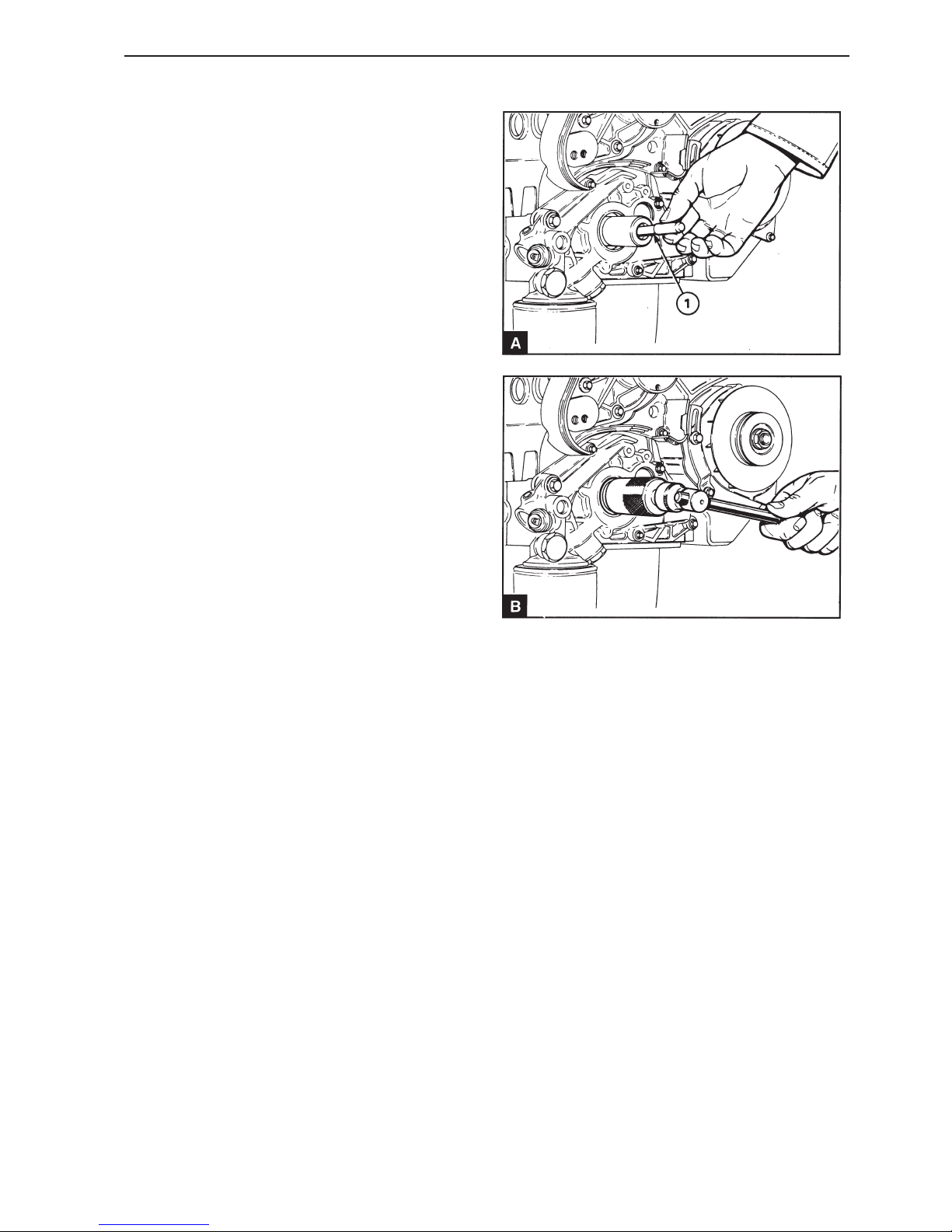
45
Crankshaft assembly
Front sealing ring,
replacement (14A-02)
Special tools: 885031, 885032, 885033, 885037
1
Disconnect the battery
2
Remove the screw from the adjustment hole on the
top of the front end of the camshaft cover (12A.03/
A4). Turn the crankshaft until the adjustment hole in
the front of the camshaft front bearing journal corresponds with the hole in the cover.
3
Install the adjustment drifts 885037 on the camshaft
and flywheel. Remove the starter motor, operation
22B-01.
4
Remove the generator (GEN) drive belt, operation
22A-03 and the pulley for the water pump.
5
Remove the crankshaft pulley, operation 14A-01A
or 14A-01B and remove the cap for the transmission cover, operation 15A-01.
6
Install two screws (M6 x 50) to secure the pulley to
the injection pump and remove the timing belt, operation 15A-04.
7
Remove the drive pulley from the crankshaft, operation 15A-07.
8
Remove the front key from the crankshaft.
9
Install the adapter (A1) from the tool 885031 at the
front end of the crankshaft. Slacken off the center
screw so that it does not reach the adapter and insert the main tool in the sealing ring. Turn the tool
clockwise to ensure that it is secure in the sealing
ring and tighten the center screw against the adapter to remove the sealing ring (B). Remove the
adapter.
10
Check that the position for the sealing ring and the
crankshaft is clean and undamaged.
Page 48
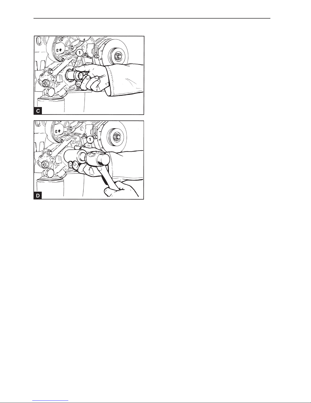
46
Crankshaft assembly
11
Install protective socket 885032 (C1) on the crankshaft. Lubricate the new sealing ring with fresh engine oil. Insert the sealing ring in position over the
protective socket with the seal lip turned towards
the engine. Remove the protective sleeve. Use installation tool 885033 (D1) and a hammer with a soft
face to drive the sealing ring into the correct position. The correct position for the sealing ring is
when the sealing ring front surface is 0.5 mm inside
the housing.
12
Install the key in the crankshaft and install the drive
pulley on the crankshaft, operation 15A-07. If the
brush seal is not installed in the cap for the timing
cover, install the crankshaft pulley, operation 14A01 or 14A-01B.
13
Install the timing belt and adjust the belt tension,
see section 15.
14
Remove the adjustment drifts and the pulley drifts.
Check the fuel injection pump adjustment, operations 17A-03.
15
Turn the crankshaft two revolutions to ensure that
there is nothing preventing free movement.
16
Install the cap for the timing cover, operation 15A-
01. If the brush seal is installed in the cap install the
crankshaft pulley, operation 14A-01A or 14A-01B.
17
Install the pulley for the water pump and the drive
belt for the generator, operation 22A-03.
18
Install the starter motor and connect the battery.
Page 49
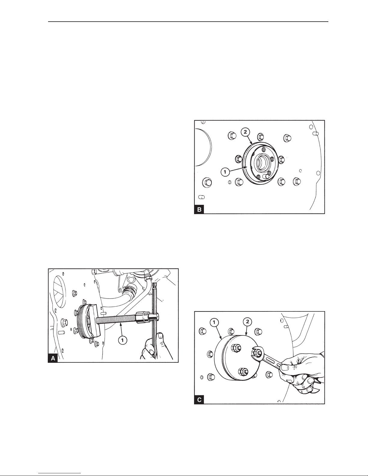
47
Crankshaft assembly
Rear sealing ring, replacement
(14A-03)
Special tools: 885030, 885034, 885035
1
Disconnect the battery
2
Remove the drive components from the rear end of
the engine.
3
Remove the flywheel, operation 21A-01.
4
Check the sealing ring position in the flywheel housing, in the separate sealing ring housing or in the
back plate. If the sealing ring rear surface is edge
to edge with the rear housing surface, the new sealing ring can be pressed further into the housing,
thus displacing the sealing rings sealing position on
the crankshaft flange. This is not possible if a 10
mm thick back plate is installed. If the crankshaft
flange is worn and a new sealing position is not possible, remove the crankshaft and machine the
flange, see Workshop Manual “Technical Data”.
5
Slacken off the screw (A1) in the puller tool so that
it does not reach the crankshaft. Insert the tool in
the sealing ring and turn it clockwise so that it fastens in the sealing ring. Use an adjustable spanner
to turn the tool body so that it fastens securely in
the sealing ring. Tighten the screw against the rear
end of the crankshaft in order to remove the sealing
ring.
6
Clean the sealing ring housing and the flange on the
crankshaft.
7
Lightly the sealing ring housing, the flange on the
crankshaft and the sealing ring seal lip with fresh
engine oil.
8
Clean and lubricate the protective socket 885030
(B1) and install it on the end of the crankshaft
flange.
9
Insert the sealing ring (B2) over the socket with the
seal lip turned towards the engine and slide it up the
flange until it enters the sealing ring housing. Remove the protective sleeve.
10
Page 50
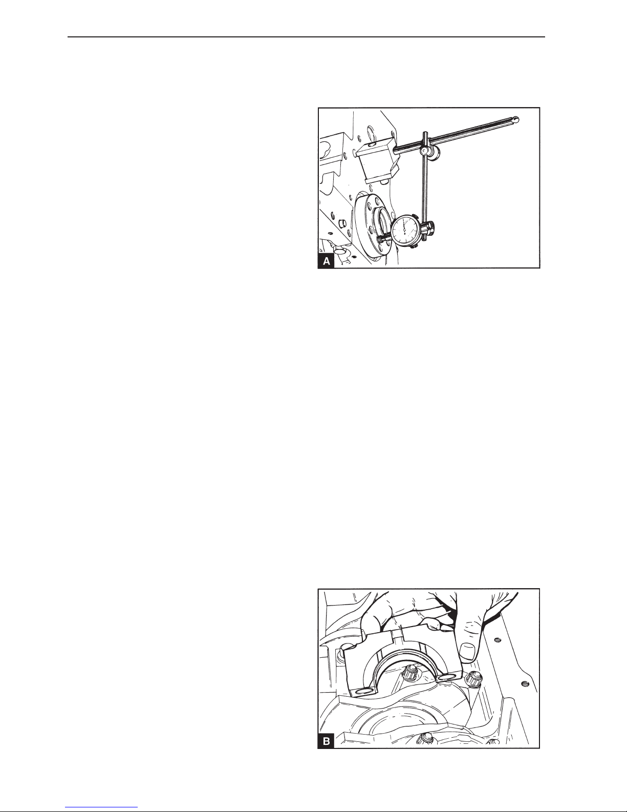
48
Crankshaft assembly
Locate the ring (C1) from tool 885035 on the crankshaft flange with the correct side of the ring towards
the sealing ring. If the sealing ring is to be installed
in the front position (see paragraph 4), install the
socket with the end with diameter markings turned
to the sealing ring. Install the plate (C2) from the
tool 885035 and use the locknuts to tighten the
studs in the crankshaft flange. Slacken off the locknuts, ensure that the plate is installed perpendicular
to the crankshaft and use the front nuts to press the
sealing ring into position. The nuts must be tightened in stages and evenly.
11
Remove the tools and install the flywheel, operation
21A-01.
12
Install the drive components on the rear end of the
engine and connect the battery.
Crankshaft axial clearance,
checking (14A-04)
The axial play of the crankshaft is controlled by two
sectioned thrust washers on each side of the central main bearing (B). The axial clearance can be
checked with a feeler gauge between a thrust washer and the crankshaft. A better method is to use a
dial indicator and measure axial clearance against
one of the crankshaft ends (A). For the correct axial
clearance, see Workshop Manual, “Technical data”.
Thrust bearing, replacement
(14A-05)
1
Drain the engine oil and remove the oil pan, operation 18A-03.
2
Remove the oil screen and extractor pipe if necessary, operation 18A-04.
3
Page 51
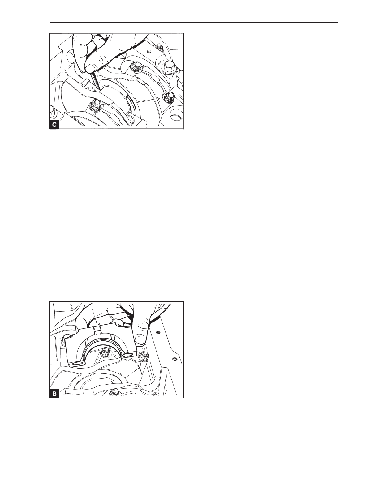
49
Crankshaft assembly
Remove the screws for the central main bearing
and remove the bearing cap assembly with the
three lower thrust washer halves (B). Press down
one end of each and every one of the upper thrust
washers with a suitable tool, made of soft material
so that the relevant thrust washer slides out of its
groove (C). If necessary move the crankshaft forwards or backwards to take the load off a thrust
washer which is trapped.
4
Lubricate the thrust washers with fresh engine oil.
5
Insert the upper thrust washer halves in their
grooves in the cylinder block. Check that the side of
thrust washer with the lubrication groove is turned
towards the crankshaft.
6
Install the lower thrust washer halves in the main
bearings with the lugs in their respective cut outs.
Check that the lubrication grooves in the thrust
washers are turned away from the bearing cap (B).
7
Check that the guide sleeves are correctly installed
in the bearing cap or in the cylinder block.
8
Check that the bearing shell is correctly installed in
the cap and that the main bearing journals are
clean. Lubricate the bearing shell with fresh engine
oil.
9
Install the bearing cap with the lugs for both bearing
shells turned in the same direction (14A.07/B1 and
B2). Tighten the screws for the main bearings in
stages and evenly to 112 Nm.
10
Check the axial clearance of the crankshaft. For the
correct axial clearance, see Workshop Manual,
“Technical data”
11
Install the oil screen and extractor pipe if required,
operation 18A-04.
12
Install the oil pan, operation 18A-03 and fill it to the
correct level with approved engine oil.
Page 52
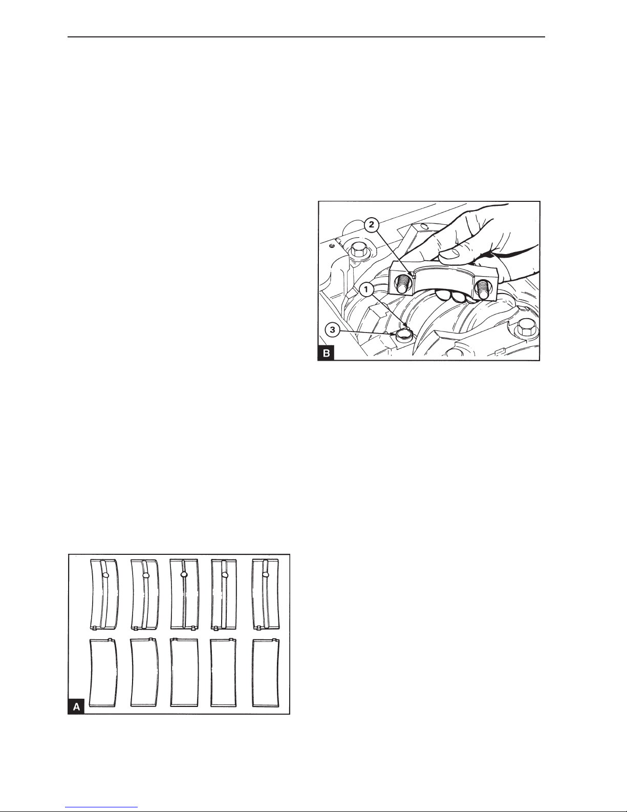
50
Crankshaft assembly
Main bearings, replacement
(14A-06)
(with crankshaft installed)
If the front bearing is to be removed the oil pump
must also be removed. Removing the main bearing
cap with the pump in position damages the pump
joint.
If the rear bearing cap is removed with the flywheel
installed, sealant must be applied to the underside
of the bearing cap rear surface before it is reinstalled.
1
Drain the engine oil and remove the oil pan, operation 18A-03.
2
Remove the oil screen and extractor pipe if required, operation 18A-04.
3
Remove the screws for the bearing cap and remove
the cap. Remove the lower bearing shell from the
cap.
4
Press the upper bearing shell on with a suitable tool
on the opposite side to the lug. This presses the lug
out of the cut out in the bearing housing. Turn the
crankshaft carefully to feed the bearing shell out of
the housing. Make a note of the respective bearing
shell locations.
5
Clean the upper bearing shell and lubricate the
bearing surface with fresh engine oil.
NOTE! There is only a lubrication hole in the upper
bearing shell and it must therefore be placed
against the cylinder block. The bearing shells for
the central main bearing are wider than the other
bearing shells (A). The bearing shells for the central
main bearing also have differently located lugs.
6
Insert the flat edge of the upper bearing shell between the main bearing journals and the side of the
bearing housing which has a cut out for the lug.
Slide the bearing shell into the bearing housing until
the lug on the bearing shell is well inside the cut out
in the bearing housing (B1).
7
Clean the lower bearing shell and lubricate the bearing surface with fresh engine oil.
8
Install the bearing shell in the cap with the lug slid
well into the cut out in the cap (B2).
9
Check that the guide sleeves (B3) are correctly installed in the bearing cap or in the cylinder block.
Install the bearing cap so that both the bearing
shells lugs are turned in the same direction.
Page 53

51
Crankshaft assembly
10
Check the mounting screws for wear and deformation and replace them if required. Lightly lubricate
the threads with engine oil. Install the screws and
washers and tighten the screws in stages and evenly to 112 Nm.
11
Check that the crankshaft can be freely turned. If
the thrust washers have been removed and reinstalled, check crankshaft axial clearance, operation
14A-03.
12
Install the oil screen and extractor pipe if required,
operation 18A-04.
13
Install the oil pan, operation 18A-03 and fill it to the
correct level with approved engine oil.
Crankshaft, replacement
(14A-08)
1
Drain the engine oil and the engine coolant system.
2
Remove the oil pan, operation 18A-03. Remove the
oil screen and extractor pipe 18A-04.
3
Remove the crankshaft pulley, operation 14A-01.
Remove the water pump pulley.
4
Remove the cap of the timing cover, operation 15A-
01.
5
Remove the flywheel and flywheel cover, section
21.
6
Turn the crankshaft until the pistons are at the
same height in the cylinder bores.
7
Temporarily mark the timing belt and the appropriate teeth on the crankshaft pulley, camshaft pulley
and the injection pump pulley. This is to ensure
that the belt can be reinstalled in the correct position.
8
Remove the timing belt, pulleys and timing cover,
section 15.
9
Remove the oil pump, operation 18A-06.
10
Measure the crankshaft axial clearance to determine if new thrust washers are required.
Main bearings, inspection
(14A-07)
Check the bearings for wear and damage. If a bearing is worn or damaged, replace both the bearing
shells and check the condition of the other bearings.
Page 54
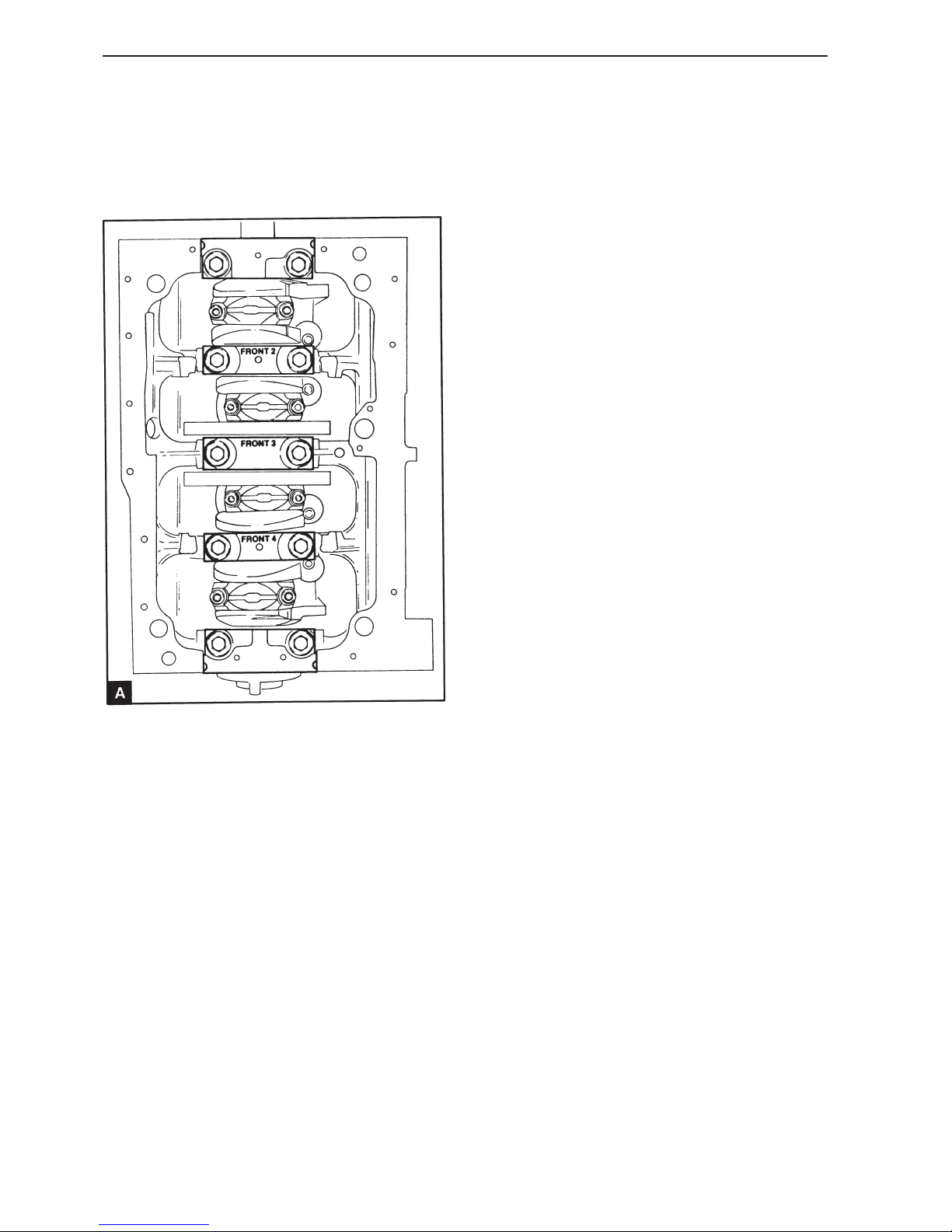
52
Crankshaft assembly
11
Check that all the big end caps are marked with the
number of the relevant cylinder. Remove the caps
and the lower big end shells, operation 13A-01.
12
16
Clean the main bearing housing and the bearing
shells. Install the bearing shells with the lugs well
into the cut outs. The upper main bearing shells
have oil holes and grooves and the center bearing is
wider than the others. Lubricate the bearings with
fresh engine oil.
17
Check that the crankshaft bearing journals are
clean and lubricate them with fresh engine oil. Carefully lower the crankshaft into position above the
bearings.
18
Clean and lubricate the upper halves of the thrust
washer and slide them in on their grooves on both
sides of the bearing housing. Ensure that the thrust
washer lubricating grooves are turned towards the
crankshaft.
19
Clean the bearing caps and the lower bearing
shells. Install the bearings in the caps with the lugs
correctly installed in their cut outs. Lubricate the
bearings with fresh engine oil.
20
Check that the guide sleeves for the main bearing
caps are correctly installed in the bearing cap or in
the cylinder block.
21
Clean the lower halves of the thrust washers and lubricate them with fresh engine oil. Install the thrust
washers against the central main bearing cap with
the oil grooves turned away from the cap. Check
that the guide sleeves of the cap are in the correct
position. Install the cap on the cylinder block with
the word “FRONT” turned towards the timing cover
end of the engine. Tighten the screws for the cap in
stages and evenly to 112 Nm.
22
Install the other caps in their correct positions.
Caps number 2 and 4 are stamped with the position
number and the word “FRONT”. The word “FRONT”
must be turned towards the timing cover end of the
engine. The front and rear caps have no stamped
number. The front cap has a threaded hole in the
underside, the rear cap has two threaded holes on
the underside. Tighten the screws for the cap in
stages and evenly to 112 Nm.
The inner main bearing caps are marked with 2, 3
and 4 and the word “FRONT” to mark the correct installation position (A). Remove the main bearing
caps, the lower main bearing shells and the thrust
washers. Keep the bearings with their respective
caps. Press out the upper halves of the thrust
washers.
13
Remove the crankshaft.
14
Remove the upper bearing shells of the main bearings and big ends and keep them together with their
respective caps.
15
Ensure that the oilways are clean and unobstructed.
Clean the sealing grooves in the sides of the front
and rear main bearing caps.
Page 55
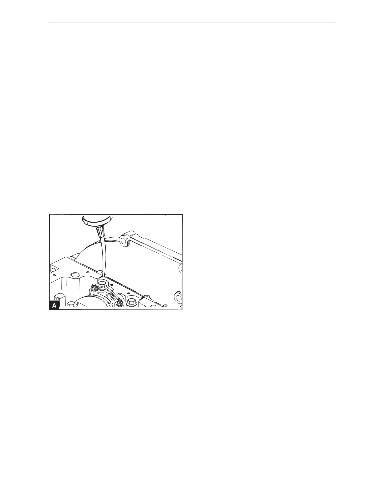
53
Crankshaft assembly
Apply sealing compound in the groove on each side
of the front and rear main bearing cap (A). Apply the
sealing compound until it fills the groove completely
and is pressed into the column between the cap and
the cylinder block. Remove the sealant from the areas around the oil pan mounting holes. Install the oil
pan, operation 18A-03 within five minutes of applying the sealing compound.
29
Install the timing cover and the timing pulleys, see
section 15. Install the timing belt, operation 15A-04,
with the temporary markings on the belt aligned to
the marked teeth on the pulleys. Remove the temporary markings and adjust the belt tension, operation 15A-03.
30
Check the fuel injection pump adjustment, operations 17A-03.
31
Install the cap of the timing cover, operation 15A-
01.
32
Install the crankshaft pulley, operation 14A-01.
33
Install the pulley for the water pump.
34
Install the starter motor, operation 22B-01.
35
After the engine is installed fill the oil pan to the correct level with an approved engine oil. Fill the engine coolant system.
23
Check the axial clearance of the crankshaft and replace the thrust washer if necessary.
24
Remove the protective tubes from the connecting
rod screws.
25
Install the big end caps, see operation 13A-03.
26
Install the oil extractor pipe, oil screen and oil pan,
section 18.
27
Install the flywheel cover and the flywheel, see section 21.
28
Crankshaft, inspection
(14A-09)
Check the crankshaft for wear and damage. The
maximum permitted wear and ovality in the main
bearing journals and crankshaft journals is 0.03
mm.
Main bearing journals and crankshaft journals can
be worked to 0.3 mm undersize in diameter, see
Workshop Manual “Technical Data”. Special bearings for under size are available.
The mating surface on the rear flange can be
worked to remove wear marks, if the seal has been
installed in both positions see Workshop handbook
“Technical data”.
Page 56
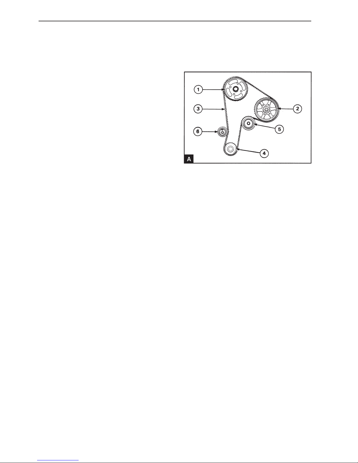
54
Timing cover and sprocket
General
The drive pulleys are installed on the camshaft (A1)
and the fuel injection pump (A2). These pulleys are
driven by a toothed belt (A3) from one toothed pulley mounted on the crankshaft (A4). The pulleys are
made of sintered iron with 2% copper and the belt is
made of neoprene and glass fibre. A flat idler pulley
(A5) ensures good belt position and an adjustable
tension pulley controls the belt tension.
The pulley for the fuel injection pump has two key
grooves, one for turbo charged engines and the other for naturally aspirated engines.
The pulleys and belt are covered by a timing cover
and a cap which is made of fibreglass reinforced
polypropylene.
Page 57
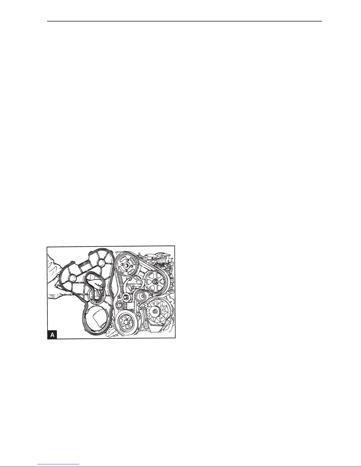
55
Repair Instructions
Timing cover outer,
replacement (15A-01)
1
Disconnect the battery.
2
Remove the generator (GEN) drive belt, operation
22A-03.
3
Remove the pulley for the water pump.
4
Remove the inspection hatch from the timing cover
(15A.04/A).
5
Remove the clips for the cover and remove the cap
(A).
6
Check that the cap is clean and that all the spring
clips are fastened at the timing cover.
7
Install the cap on the timing cover and ensure that
all the clips are in position.
8
Install the inspection hatch on the timing cover and
the cap.
9
Install the water pump belt.
10
Install the generator (GEN) belt, operation 22A-03.
11
Connect the battery.
Page 58
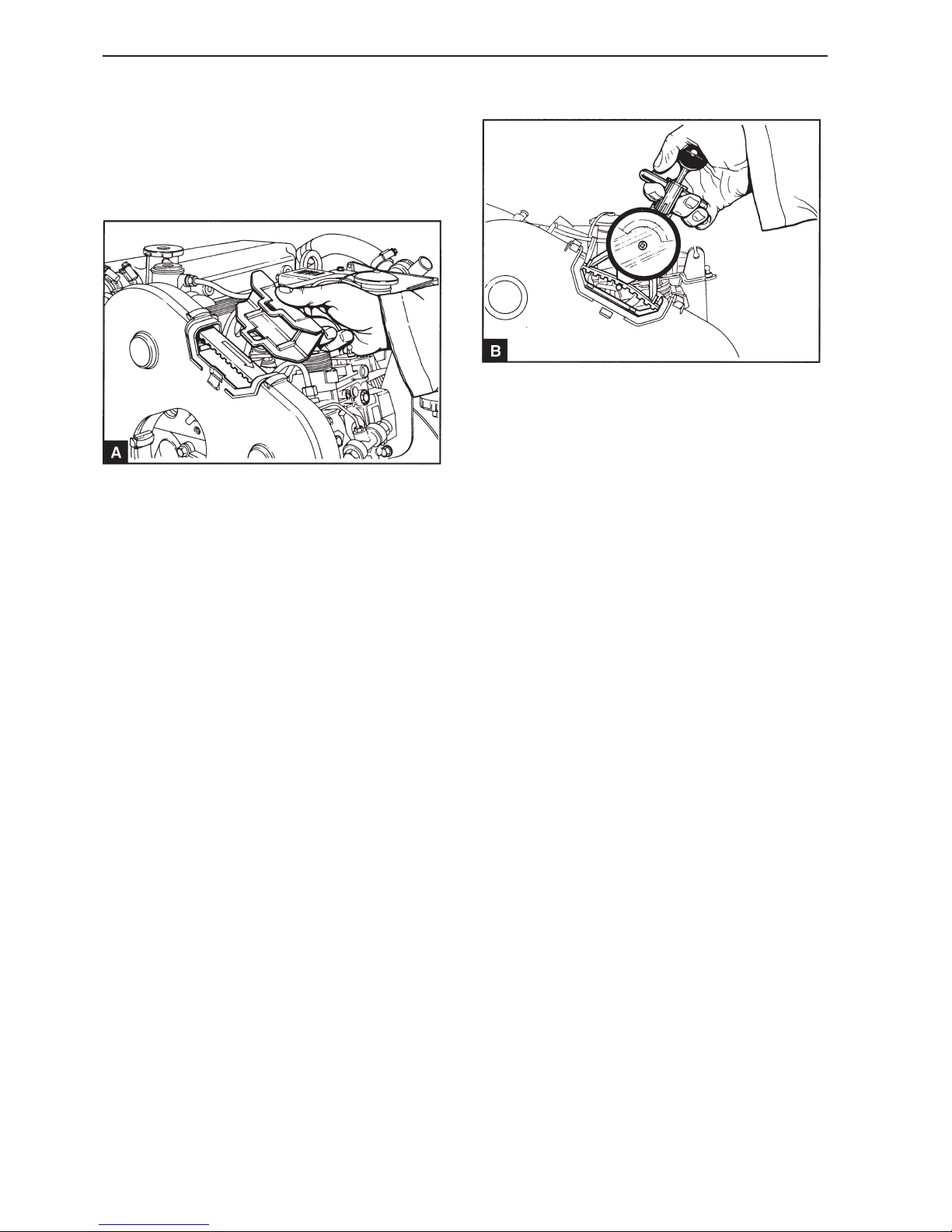
56
Timing cover and drive
Timing belt, inspection
(15A-02)
Special tools: 885036
1
Remove the inspection hatch from the upper side of
the timing cover (A).
2
Make a temporary mark on the belt to ensure that
the whole belt is checked. Check the belt for wear
and damage and check that the belt is not split or
contaminated by oil. Turn the crankshaft so that all
the teeth on the belt can be checked. Replace the
belt if necessary, operation 15A-04. Remove the
temporary mark.
3
Press the ball end of the belt tension gauge and install the gauge over the belt. Ensure that the gauge
foot is located under the belt and between two teeth
(B). Slowly release the ball end and read off the
gauge. Turn the crankshaft slightly in each direction
until a stable read off is obtained. The correct value
for a new belt is 425-465 N and for a used belt 340370 N. If the tension of a used belt has fallen to 270
N or below, adjust the belt tension to 340-370 N, operation 15A-03.
4
If belt tension is correct, install the inspection hatch
on the timing cover.
Page 59
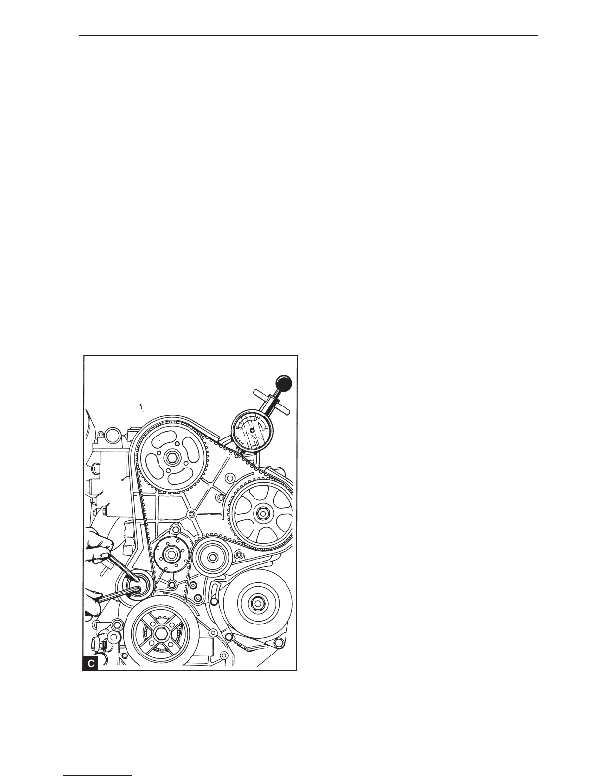
57
Timing cover and drive
Timing belt, tension (15A-03)
Special tools: 885036, 885037
1
Install the adjustment drifts on the camshaft and flywheel, operation 17A-01.
2
Remove the cap of the timing cover, operation 15A-
01.
3
Install the belt tension gauge between the belts for
the injection pump and the camshaft.
4
Remove the four mounting for the camshaft pulley,
so that the pulley can turn on its hub.
5
Unscrew the domed screws holding the belt tensioner roller. Adjust the belt tension using a hexagonal key in the hexagonal socket in the roller (C).
The correct tension for a new belt is 425-465 N and
for a used belt 340-370 N. When the tension is correct, tighten the domed screws to 45 Nm and then
recheck the belt tension.
6
Tighten the mounting screws for the camshaft pulley to the correct torque, see Workshop manual
“Technical data” and check that the belt tension is
still correct.
7
Remove the adjustment drifts from the camshaft
and the flywheel.
8
Turn the crankshaft two revolutions and check the
belt tension again.
9
Check the fuel injection pump adjustment, operations 17A-03.
10
Install the cap of the timing cover, operation 15A-
01.
Page 60
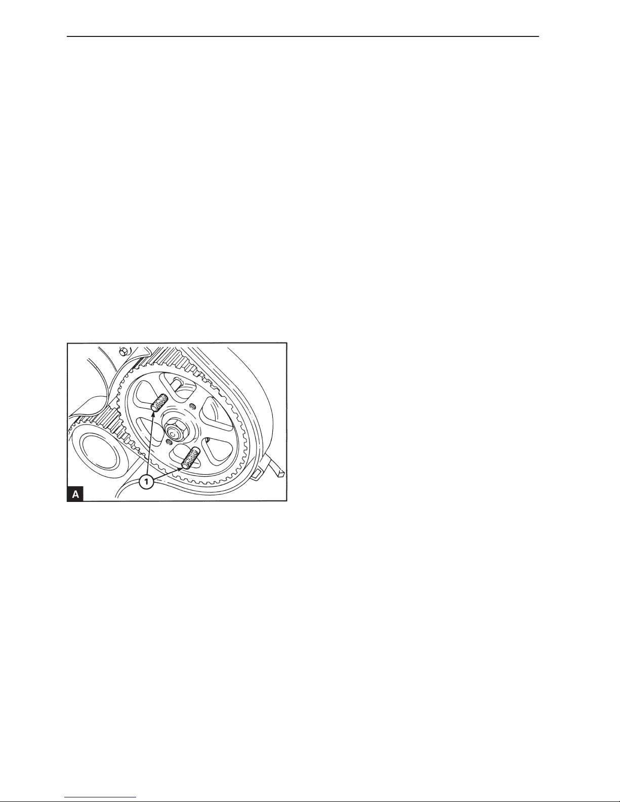
58
Timing cover and drive
Timing belt, replacement
(15A-04)
Special tools: 885037
1
Disconnect the battery.
2
Remove the screw over the adjustment hole in the
camshaft cover. Turn the crankshaft until the adjustment hole in the front of the camshaft corresponds with the hole in the cover. Install the adjustment drifts 885037 in the camshaft and the flywheel.
3
Remove the cap of the timing cover, operation 15A-
01.
4
Install the two screws (M6 x 50) (A1) through the
smooth holes in the fuel injection pump pulley and in
the pump bracket.
5
Remove the tension pulley and idler pulley.
6
Remove the timing belt. Do not bend the belt at an
angle, this can damage the belt and could cause engine seizure. Lay the belt on its edge in a circle on
a flat surface. Do not hang the belt.
7
Check the belt teeth for wear. Check the belt for oil
contamination, cracks and other damage. Replace
the belt if any fault is found.
8
Install the timing belt over the crankshaft, camshaft
and fuel injection pump pulleys. Ensure that the direction arrows show a clockwise direction of rotation when seen from the front (15A.04/A).
9
Install the idler pulley and tighten to 43 Nm.
10
Install the tension pulley in position and install the
roller domed screw. There are two threaded holes
for the domed screw and it must be placed in the
hole which makes real belt tension adjustment possible. Tighten the domed screw so that the pulley is
held in position, but do not tighten completely.
11
Remove the fixing screws from the fuel injection
pump pulley and adjust the belt tension, operation
15A-03.
12
Tighten the mounting screws for the camshaft pulley to the correct torque, see Workshop manual
“Technical Data” and remove the rotation locking
tool.
13
Remove the adjustment drifts from the camshaft
and the flywheel.
14
Check the fuel injection pump adjustment, operations 17A-03.
15
Turn the crankshaft two revolutions to ensure that
there is nothing preventing free movement
Page 61
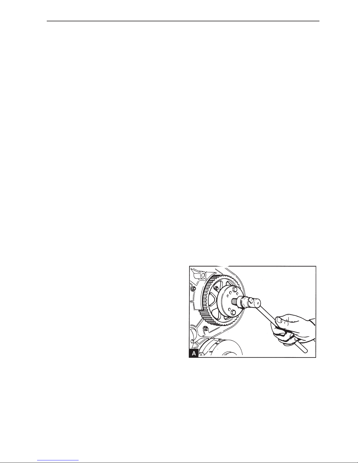
59
Timing cover and drive
16
Install the cap of the timing cover, operation 15A-01
and install the inspection hatch.
17
Install the mounting screw in the adjustment hole in
the camshaft cover.
18
Connect the battery.
Fuel injection pump pulley,
replacement (15A-05)
Special tools: 885037, 885027, 885029
1
Disconnect the battery.
2
Remove the screw over the adjustment hole in the
camshaft cover. Turn the crankshaft until the adjustment hole in the front of the camshaft corresponds with the hole in the cover. Install the adjustment drifts 885037 in the camshaft and the flywheel.
3
Remove the cap of the timing cover, operation 15A-
01.
4
Slacken off and remove the nut for the fuel injection
pump pulley. Unscrew the mounting screws for the
camshaft pulley.
5
Remove the timing belt, operation 15A-04.
6
Remove the pulley with pulley puller 885027 and
adapters 885029. Take care not to lose the key.
Page 62
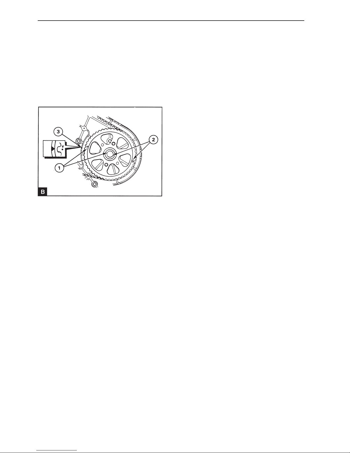
60
Timing cover and drive
7
Check the pulley for wear, cracks and other damage. Replace it if required.
8
Check that the key is correctly installed in the fuel
injection pump shaft.
9
Install the pulley in position on the shaft with the
correct keygroove in contact with the key. There
are two keygrooves and two marked teeth, “A” and
“B”, on the pulley. On engines types MD22 and
MD22L use the keygroove lying on the same side
as the tooth marked “A”. On engines types TMD22
and TAMD22 use the keygroove lying on the same
side as the tooth marked “B”. Ensure that the marking on the pulley is turned to the front end of the engine.
10
Install the spring washer and the pulley nut, hold the
pulley so that it does not move and tighten the nut
to press the pulley into position.
11
Check that the tooth with the correct marking (see
paragraph 2) is closest to the arrow on the timing
cover (B3). Install the two screws (M6 x 50) through
the smooth holes in the pulley and in the pump
bracket.
12
Install the timing belt, operation 15A-04. Remove
the fixing pin for the pulley and adjust the belt tension, operation 15A-03.
13
Tighten the pump pulley to 60 Nm and remove the
locking tool.
14
Remove the adjustment drifts from the camshaft
and the flywheel.
15
Check the fuel injection pump adjustment, operations 17A-03.
16
Turn the crankshaft two revolutions to ensure that
there is nothing preventing free movement
17
Install the cap of the timing cover, operation 15A-01
and install the inspection hatch.
18
Install the mounting screw in the adjustment hole in
the camshaft cover.
19
Connect the battery.
Page 63
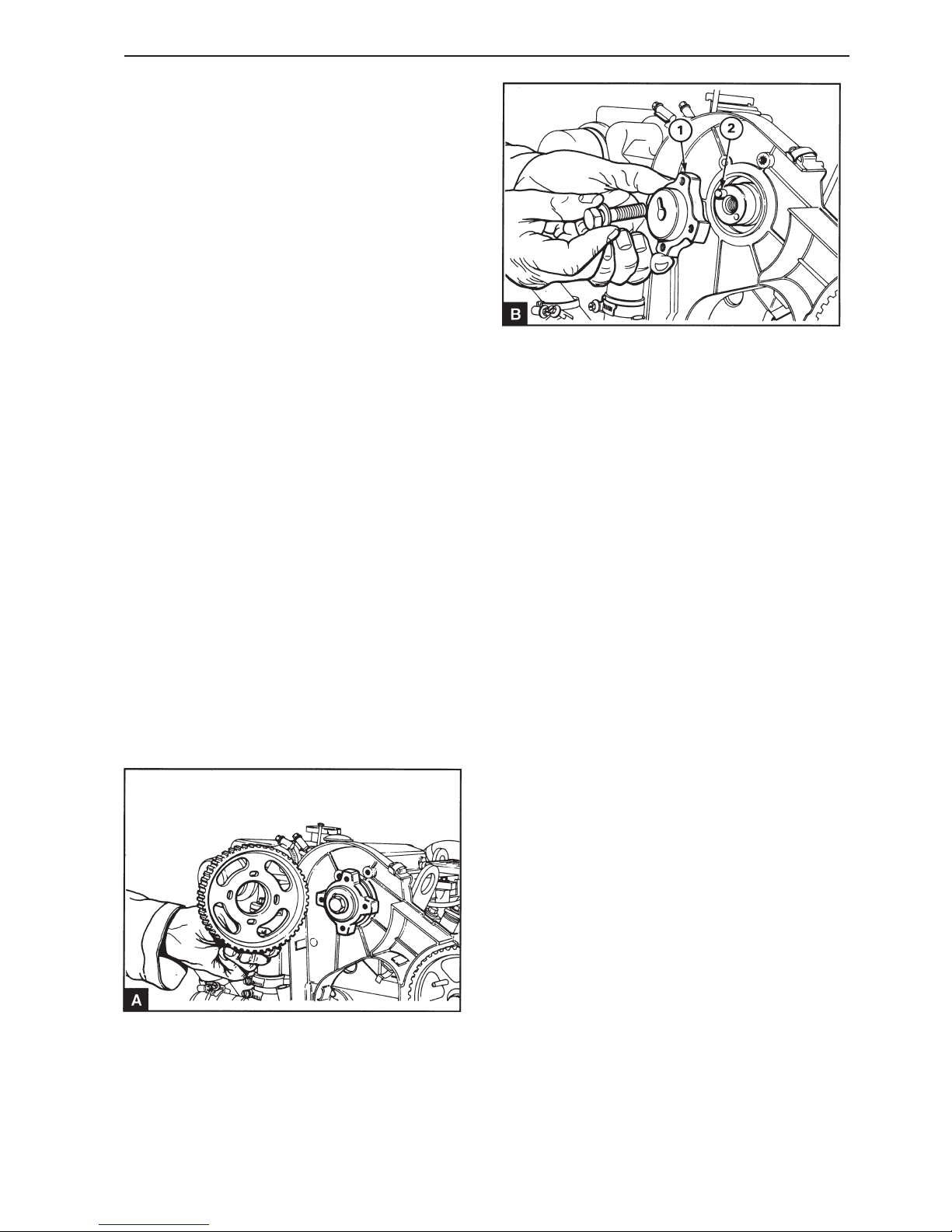
61
Timing cover and drive
Camshaft pulley, replacement
(15A-06)
Special tools: 885027, 885029, 885037
1
Disconnect the battery.
2
Remove the screw over the adjustment hole in the
camshaft cover. Turn the crankshaft until the adjustment hole in the front of the camshaft corresponds with the hole in the cover. Install the adjustment drifts 885037 in the camshaft and the flywheel.
3
Remove the cap of the timing cover, operation 15A-
01.
4
Install the two screws (M6 x 50) through the smooth
holes in the fuel injection pump pulley and in the
pump bracket.
5
Unscrew the screws securing the pulley to the hub.
6
Remove the timing belt, operation 15A-04.
7
Remove the mounting screws for the pulley and remove the pulley. Remove the pulley hub (B1) and
the guide pin (B2).
8
Check the pulley for wear, cracks and other damage. Replace it if required.
9
Check that the guide pin (B2) is in position on the
camshaft. Install the hub and the mounting screws,
but do not tighten the screw completely. Install the
pulley on the hub if necessary, but do not tighten
the screws completely.
10
Install the timing belt, operation 15A-04. Remove
the fixing pin for the fuel injection pump pulley and
adjust the belt tension, operation 15A-03.
11
Tighten the central mounting screw to 85 Nm and/or
tighten the screws which secure the pulley to the
hub to 22 Nm. Remove locking tool.
12
Remove the adjustment drifts from the camshaft
and the flywheel.
13
Check the fuel injection pump adjustment, operations 17A-03.
Page 64
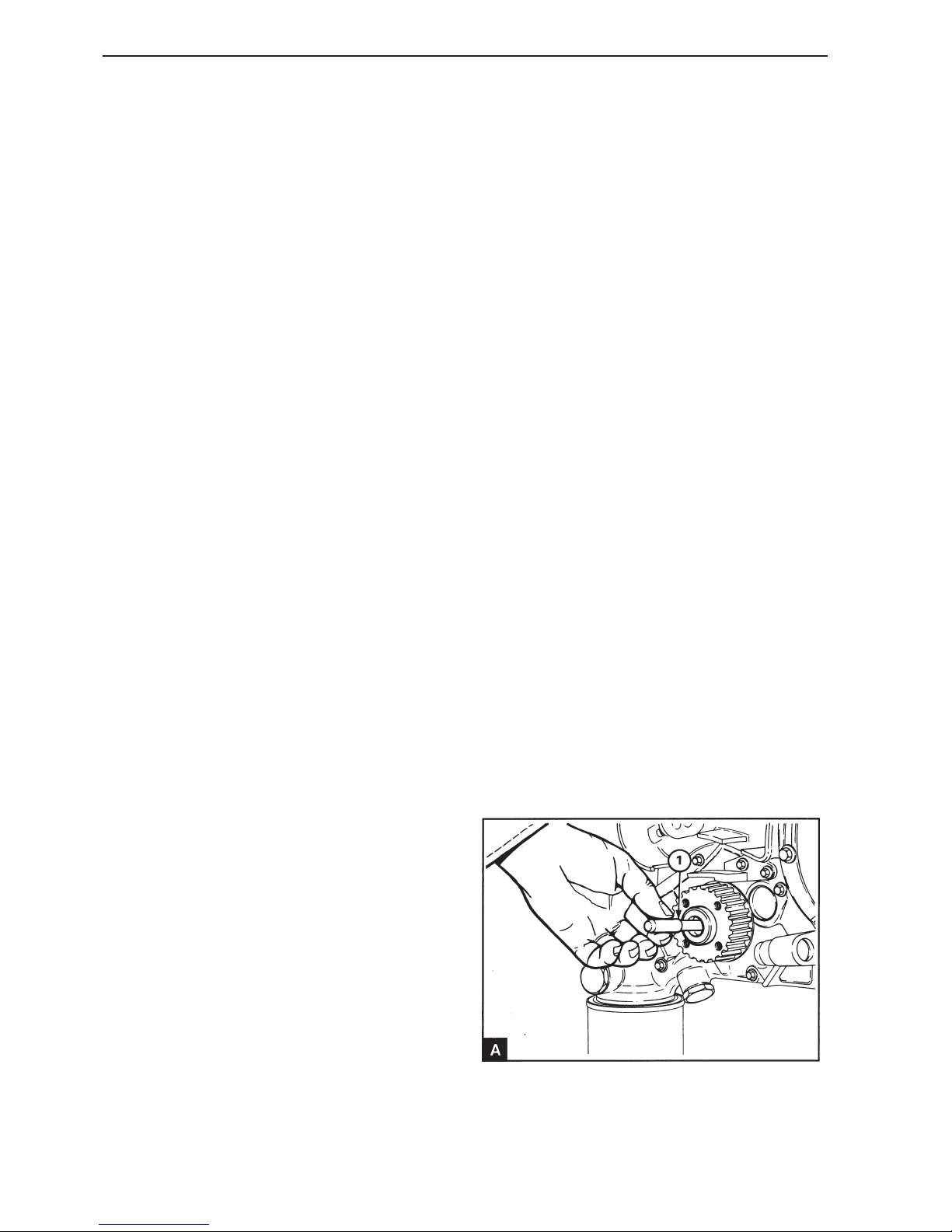
62
Timing cover and drive
14
Turn the crankshaft two revolutions to ensure that
there is nothing preventing free movement
15
Install the cap of the timing cover, operation 15A-01
and install the inspection hatch.
16
Install the mounting screw in the adjustment hole in
the camshaft cover.
17
Connect the battery.
Crankshaft pulley, replacement
(15A-07)
Special tools: 885029, 885027, 885037
1
Disconnect the battery.
2
Remove the screw over the adjustment hole in the
camshaft cover. Turn the crankshaft until the adjustment hole in the front of the camshaft corresponds with the hole in the cover. Install the adjustment drifts 885037 in the camshaft and the flywheel.
3
Remove the starter motor.
4
Remove the crankshaft pulley, operation 14A-01.
5
Remove the cap of the timing cover, operation 15A-
01.
6
Remove the timing belt, operation 15 A-04.
NOTE! The belt pulley is locked to the front end of
the crankshaft using Loctite 648 and can only be removed using a puller.
7
Page 65
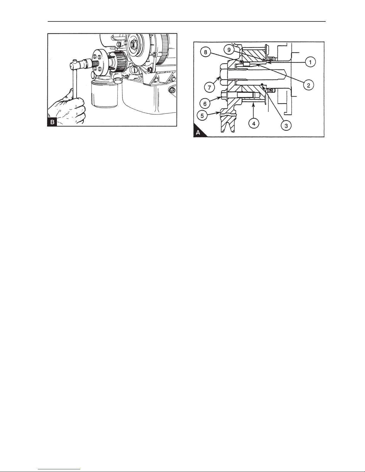
63
Timing cover and drive
Insert the thin end spacer piece in the crankshaft
(A1). Install the main tool 885027 (B) on the pulley
using the mounting screws and tighten the center
screws against the spacer piece to remove the pulley.
8
Check the pulley for wear, cracks and other damage. Replace it if necessary.
9
If the pulley is to be reused, the old Loctite 648
must be removed from the crankshaft, pulley and
key using Loctite 8151 according to the manufacturers instructions.
NOTE! It is acceptable for some of the old Loctite
648 to remain on the components, if the pulley can
be mounted correctly New Loctite can bond to old
Loctite if it is clean, dry and free of any cleaning
agent.
10
If old Loctite remains on the components and the
pulley cannot be correctly installed extra working
with the Loctite tool is needed.
11
Ensure that the hole in the pulley, the keygroove
and the front end of the crankshaft are dry and free
of grease, cleaning agent and external inhibitors.
12
Apply a bead of Loctite 648 (A3) in a complete circle internally in the hole in the pulley (A4), 6.5 mm
from the rear end panel.
13
Install the pulley on the crankshaft, but do not align
the keygroove.
14
Spray Loctite 648 into the keygroove (A2) in the pulley. Ensure that the pulley is pressed against the
projection (A1) on the crankshaft during this operation. This prevents the oil seal (A9) being contaminated by the Loctite.
NOTE! If too much Loctite is sprayed into the keygroove it can contaminate the oil seal (A9) behind
the pulley. If this occurs the oil seal must be replaced.
15
Turn the pulley through 360° to spread the Loctite
over the surface of the hole in the pulley and on the
front end of the crankshaft.
16
Align the keygroove in the crankshaft and the pulley
and carefully spray Loctite 648 into keygroove until
one can see Loctite fully and evenly at the front end
of the keygroove. Ensure that the pulley is pressed
against the projection on the crankshaft during this
operation.
Page 66

64
Timing cover and drive
17
Slide the (A8) into the keygroove to a depth of 5 mm
measured from the pulley front end plate.
NOTE! It is important that all excess Loctite is
wiped off from the front end of the crankshaft and
from the pulley before the pulley is installed.
18
Install the damper pulley (A5) on the pulley using
the four mounting screws (A6). Finger tighten the
mounting screws.
19
Install the center screw (A7) and tighten to 180 Nm.
20
Tighten the four mounting screws to:
Flanged screw 22 Nm
Domed screws 36 Nm
NOTE! Loctite 648 starts to cure after seven minutes at 22° C. It is important to tighten the these
mounting screws within the given time limit.
21
Install the timing belt, operation 15A-04. Remove
the fixing pin for the fuel injection pump pulley and
adjust the belt tension, operation 15A-03.
22
Check the fuel injection pump adjustment, operations 17A-03.
23
Carefully turn the crankshaft two revolutions to ensure that there is nothing preventing free movement.
24
Install the cap of the timing cover, operation 15A-01
and install the inspection hatch.
25
Install the screw in the adjustment hole in the camshaft cover.
26
Install the starter motor, operation 23B-01.
27
Connect the battery.
Page 67
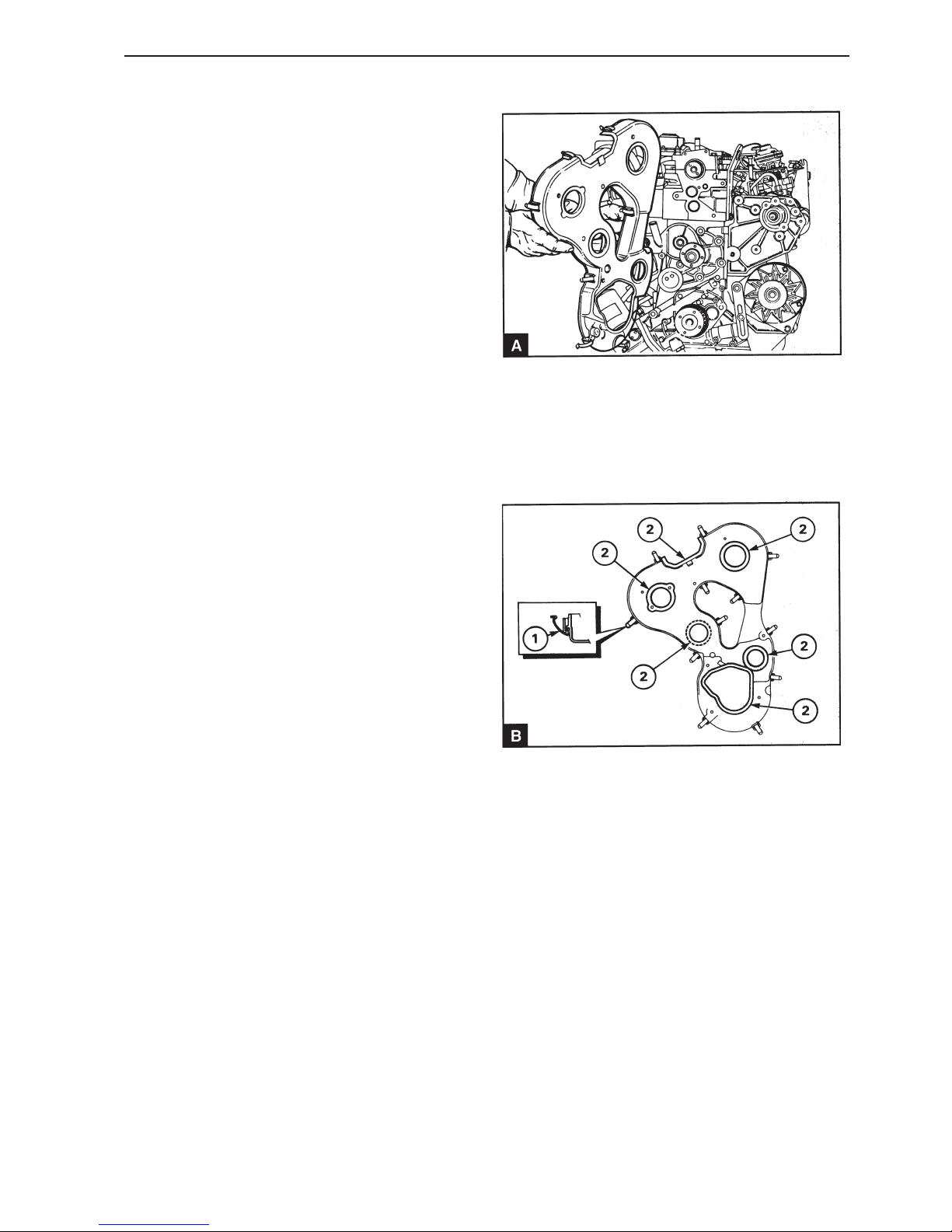
65
Timing cover and drive
Timing cover inner, replacement (15A-08)
Special tools: 885037, 885027, 885029
1
Disconnect the battery.
2
Remove the screw over the adjustment hole in the
camshaft cover. Turn the crankshaft until the adjustment hole in the front of the camshaft corresponds with the hole in the cover. Install the adjustment drifts 885037 in the camshaft and the flywheel.
3
Remove the starter motor.
4
Remove the crankshaft pulley, operation 14A-01A.
5
Remove the cap of the timing cover, operation 15A-
01.
6
Install the two screws (M6 x 50) through the smooth
holes in the fuel injection pump pulley and in the
pump bracket.
7
Remove the timing belt, operation 15A-04.
8
Remove the fuel injection pump pulley, operation
15A-05 and the camshaft pulley, operation 15A-06.
9
Unscrew the screws securing the timing cover to
the cylinder head, the cylinder block, the fuel injection pump bracket and the oil pump. Remove the
timing cover (A).
10
Check the timing cover for cracks and damage and
replace it if required. Check that all the clips are
correctly installed in the timing cover (B1).
11
Check that the mating surfaces of the timing cover
and engine are clean. Install the cover in position
and tighten with the mounting screws. Tighten the
screws to the correct torque in relation to the thread
dimension, see Workshop Manual “Technical Data”.
Page 68

66
Timing cover and drive
12
Remove the fuel injection pump pulley, operation
15A-05 and the camshaft pulley, operation 15A-06.
13
Install the crankshaft pulley if required, operation
14A-01A.
14
Install the timing belt, operation 15A-04. Remove
the fixing pin for the fuel injection pump pulley and
adjust the belt tension, operation 15A-03.
15
Remove the adjustment drifts from the camshaft
and the flywheel.
16
Check the fuel injection pump adjustment, operations 17A-03.
17
Turn the crankshaft two revolutions to ensure that
there is nothing preventing free movement
18
Install the cap of the timing cover, operation 15A-01
and install the inspection hatch.
19
Install the screw in the adjustment hole in the camshaft cover.
20
Install the starter motor, operation 22B-01.
21
Connect the battery.
Page 69

67
Cylinder block
General
The cylinder block is made of cast iron with sides
which extend below the crankshaft for maximum
support. The cylinder bore is machined directly into
the block and is specially honed to minimize wear
and oil consumption.
Repair instructions
Cylinder block, replacement
(16A.01)
1
Drain the engine oil and the engine coolant system.
2
Remove the generator (GEN) drive belt, the generator (GEN) and the mounting brackets, see 22.
3
Remove the starter motor, operation 22B-01.
4
Remove the crankshaft pulley, operation 14A-01A.
5
Remove the cap for the timing cover, the timing
belt, belt pulleys and timing cover, see section 15.
6
Remove the oil pump and filter unit, operation 18A-
06.
7
Remove the fuel filter, injectors and fuel injection
pump, see section 19.
8
Remove the reverse gear.
9
Remove the flywheel and the flywheel cover.
Page 70
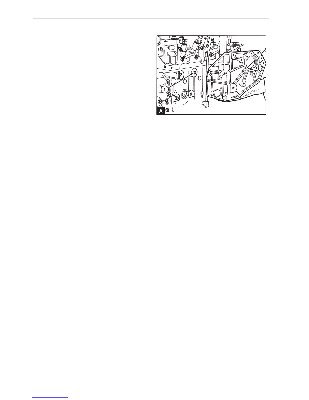
68
Cylinder block
10
Remove the cylinder head assembly, operations
12A-07.
11
Remove the oil pump, operation 20A-11.
12
Remove the oil filter/ separator unit.
13
Remove the oil pan, operation 18A-03.
14
Remove the pistons and connecting rods assembly,
operation 13A-03.
15
Remove the crankshaft pulley, operation 14A-09.
16
Remove the mounting bracket for the fuel injection
pump (A).
17
Remove the mounting screws and washers if the
cooler nozzle is not installed.
18
Clean the new cylinder block carefully. Check that
all the oilways are clear and clean. Ensure that the
plug is installed in the rear end of the pressure
channel.
19
If the cooler nozzle is not used, install the mounting
screws and washers to drain the oil hole and tighten
the screws to 22 Nm.
20
Install the fuel injection pump bracket. Check that
the guide pins (A1) is correctly installed. Tighten
the mounting screws to 43 Nm.
21
Install the crankshaft and if necessary, the separate
housing oil stuffing box, see section 14.
22
Install the pistons and connecting rods assembly,
operation 13A-03.
23
Install the oil pan, operation 18A-03.
24
Install the oil filter/ separator unit.
25
Install the flywheel cover and the flywheel, see section 21.
26
Install the oil cooler if necessary, operation 20A-11.
Page 71
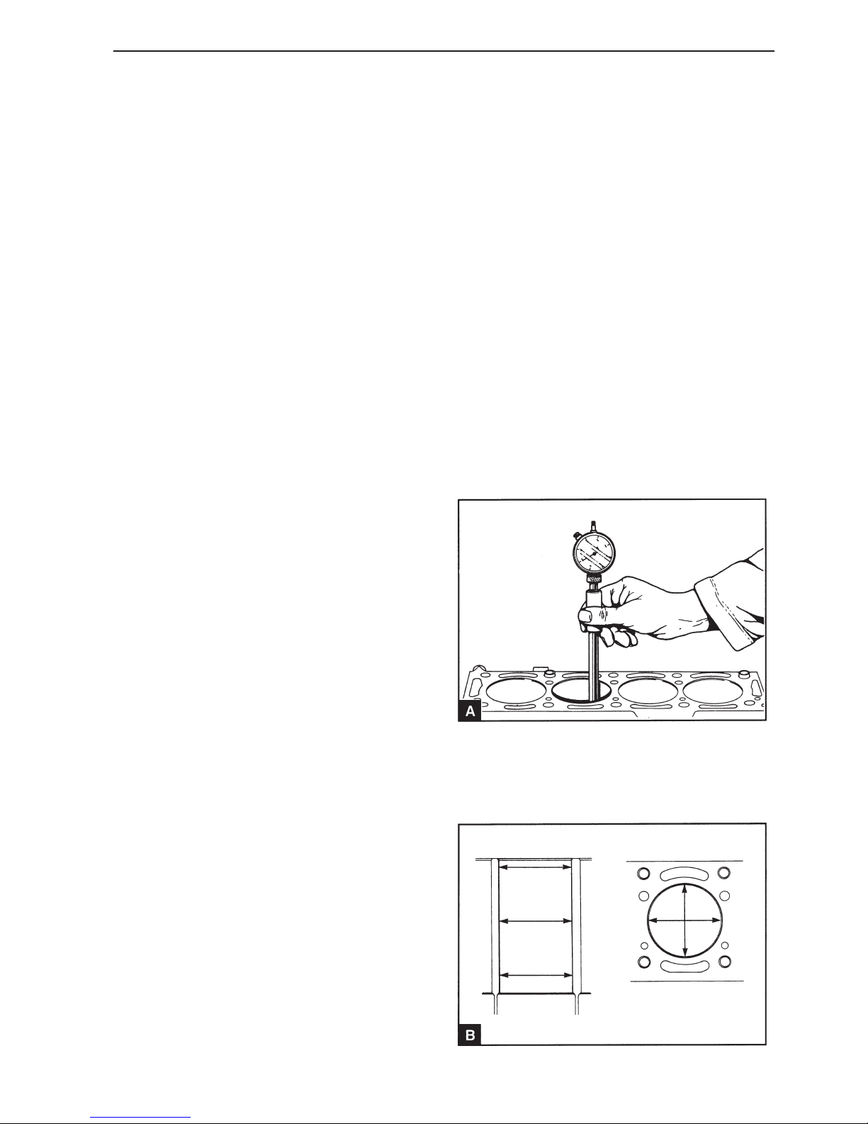
69
Cylinder block
27
Install the cylinder head assembly, operation 12A-
07.
28
Install the fuel filter, injectors and fuel injection
pump, see section 19.
29
Install the oil pump and filter unit, operation 18A-06.
30
Install the timing cover, belt pulleys and the timing
belt, see section 15. Install the crankshaft pulley,
operation 14A-01A. Adjust the timing belt tension,
operation 15A-01.
31
Remove the adjustment drifts and turn the crankshaft two revolutions. Check the fuel injection pump
setting, operation 17A-03. Install the cap of the timing cover, operation 15A-01.
32
Install the starter motor, operation 22B-01.
33
Install the generator (GEN) drive belt, the generator
(GEN) and the mounting brackets, see 22.
34
Install the engine.
35
Fill the engine coolant system.
36
Fill the oil pump to the correct level with an approved engine oil.
37
Bleed the fuel injection system, operation 19A-08.
Cylinder block, inspection
(16A-02)
1
Clean the coolant and lubrication channels.
2
Check the cylinder block for cracks and other damage.
The upper surface of the cylinder block cannot normally be machined, because it affects the height of
the pistons above the cylinder block surface. If high
pistons (height class 1) are installed in all cylinders
it is possible to machine a maximum of 0.26 mm
from the upper surface of the cylinder block and install low pistons (height class 6). If the block is machined the piston height must be checked to ensure
that the pistons do not reach further than the maximum permitted limit, otherwise the pistons may hit
the valves and damage the engine.
3
Check the cylinder bore for wear (A) and damage.
The top, bottom and center of the cylinder bore
should be inspected in both the vertical and lateral
planes (B).
Page 72
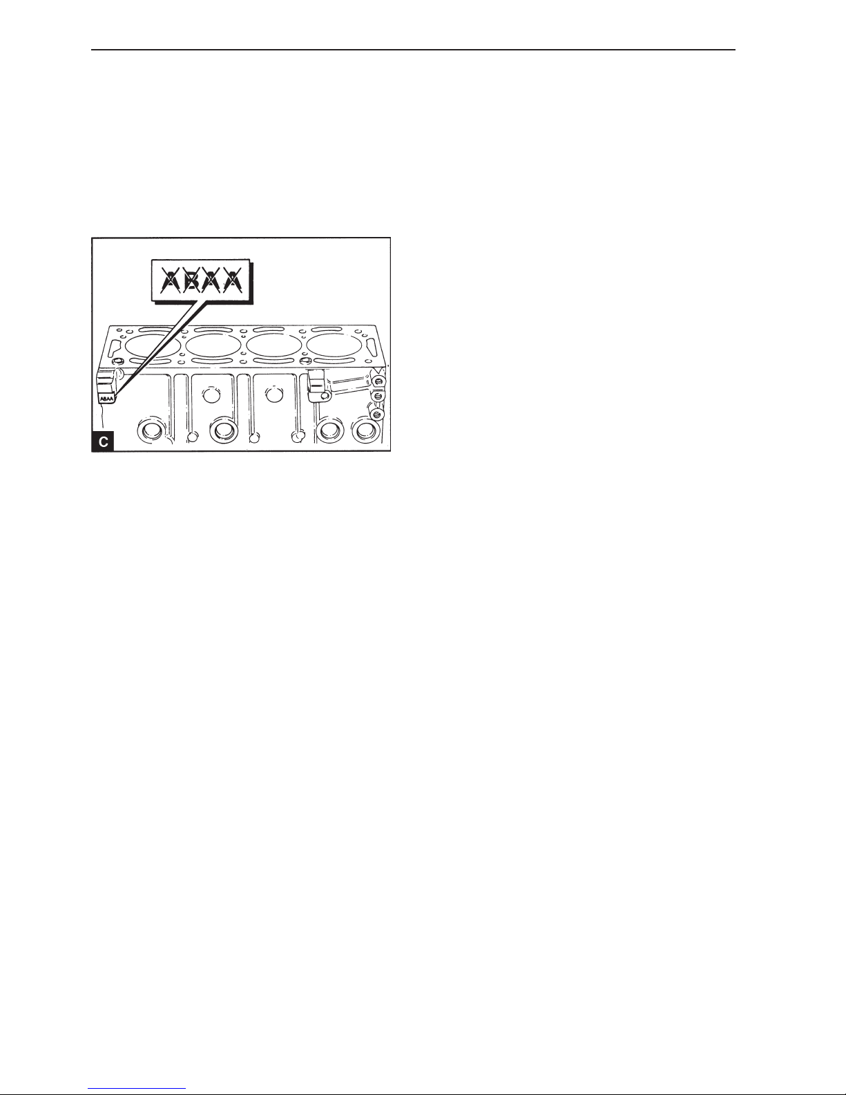
70
Cylinder block
If the cylinder bores are damaged or worn more
than 0.15 mm, measured in the diameter, the bore
can be bored out and honed to 0.50 mm, diametrically oversize, and oversized pistons can be installed. For best results the cylinder bore should be
honed with a total angle of 30° to 35° with a silicon
carbide honing element which gives clean scoring.
Coarse hone with a surface evenness of 1.5-2.0
mm (micrometer) and then fine hone to an mean
evenness of 0.7-1.4 mm.
After the cylinder has been bored out to oversize,
an “X” should be stamped over the bore classes on
the cast lug on the rear of the right hand size of the
cylinder block (C).
If the cylinder bore surface is glazed the engine
may have high oil consumption with very low cylinder bore wear.
2
A new Flex-Hone must be used on an old cylinder
bore first in order to remove any loose material and
sharp edges.
3
Lubricate the cylinder head and Flex-Hone lightly
with fresh engine oil.
4
Install the tool in position at the top of the cylinder
bore, but do not push the tool down into the cylinder
bore until it has begun to operate.
5
Allow the tool to operate and move it up and down in
the cylinder bore once a second for 30-50 seconds.
Pull the tool up while it is rotating.
6
Clean the cylinder bore carefully to remove all dirt
from the machining, use a hard brush and kerosene.
7
Dry the cylinder bore and carefully remove all the
covers used to protect the components. Carefully
clean all the engine components exposed to machining particles.
8
Ensure that new piston rings are installed when the
engine is reassembled.
NOTE! After honing, we recommend that the following instructions are followed for the first 5 hours of
operational use:
• Do not run the engine at maximum load.
• Do not run the engine at high engine speeds
(RPM).
• Do not run the engine at low idling speed for
long periods of time.
Cylinder bore, honing (16A-03)
A tool, called Flex-Hone is accessible for adjusting
the cylinder bore surface. This tool can be used together with an electric drill at low speeds. The pistons and connecting rods must be removed. Use
covers to protect all the engine components from
swarf that occurs during the machining.
1
An 80SC Flex-Hone with the grade 3 1/2 can be
used.
Page 73

71
Engine settings
General
The installation holes for the adjustment drifts are in
the flywheel and in the front camshaft bearing journal. When these holes are aligned to the adjustment
holes in the flywheel cover and the camshaft cover
the cylinder 1 piston should be in the Top dead
center (TDC) position of the compression stroke.
The fuel injection pump pulley has two adjustment
marks (A and B) and two keygrooves. The keygroove on the same side as the relevant adjustment
mark must always be used.
Setting the fuel injection pump must always be
checked after the timing belt tension has been adjusted.
Page 74
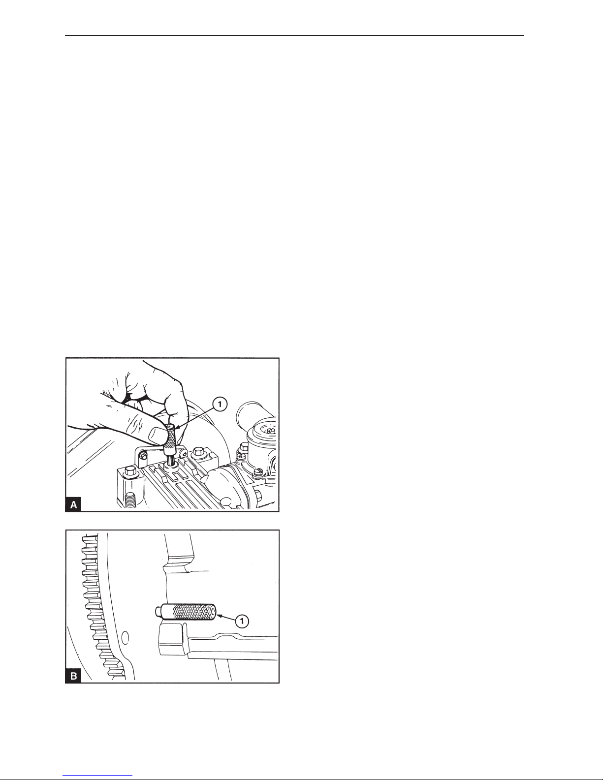
72
Repair Instructions
Setting the 1st piston at top
dead center of the compression stroke (17A-01)
Special tools: 885037
1
Disconnect the battery and remove the screw over
the adjustment hole at the top of the front end of the
camshaft cover.
2
Turn the crankshaft (in the normal direction of rotation – clockwise as seen from the front) until the adjusting hole in the crankshaft front bearing journal
corresponds to the hole in the camshaft cover.
3
Install the adjustment drifts through the camshaft
cover in the camshaft (A1) and through the flywheel
cover in the flywheel (B1).
Valve timings, checking/
adjustment (17A-02)
Special tools: 885037
Position the piston in cylinder 1 at TDC in the compression stroke, operation 17A-01 If both the adjustment drifts can be installed, the valve timing is correct. If only one of the drifts can be installed, adjust
the valve timings as follows:
1
If necessary remove the drift from the flywheel, turn
the crankshaft to align the adjustment hole in the
crankshaft to the hole in the camshaft cover and install the adjustment drift for the camshaft.
2
Remove the cap of the timing cover, operation 15A-
01.
3
Slacken off the screws securing the camshaft pulley to the hub, so that the pulley can move on the
hub.
4
Unscrew the dome screw for the tension pulley and
loosen the timing belt tension.
5
Turn the crankshaft to align the adjustment hole in
the flywheel to the hole in the flywheel cover or
back plate. Install the adjusting drift on the flywheel.
6
Adjust the timing belt tension, operation 12A-03.
7
Tighten the mounting screws for the camshaft pulley to the correct torque, see Workshop manual
“Technical Data”.
Page 75
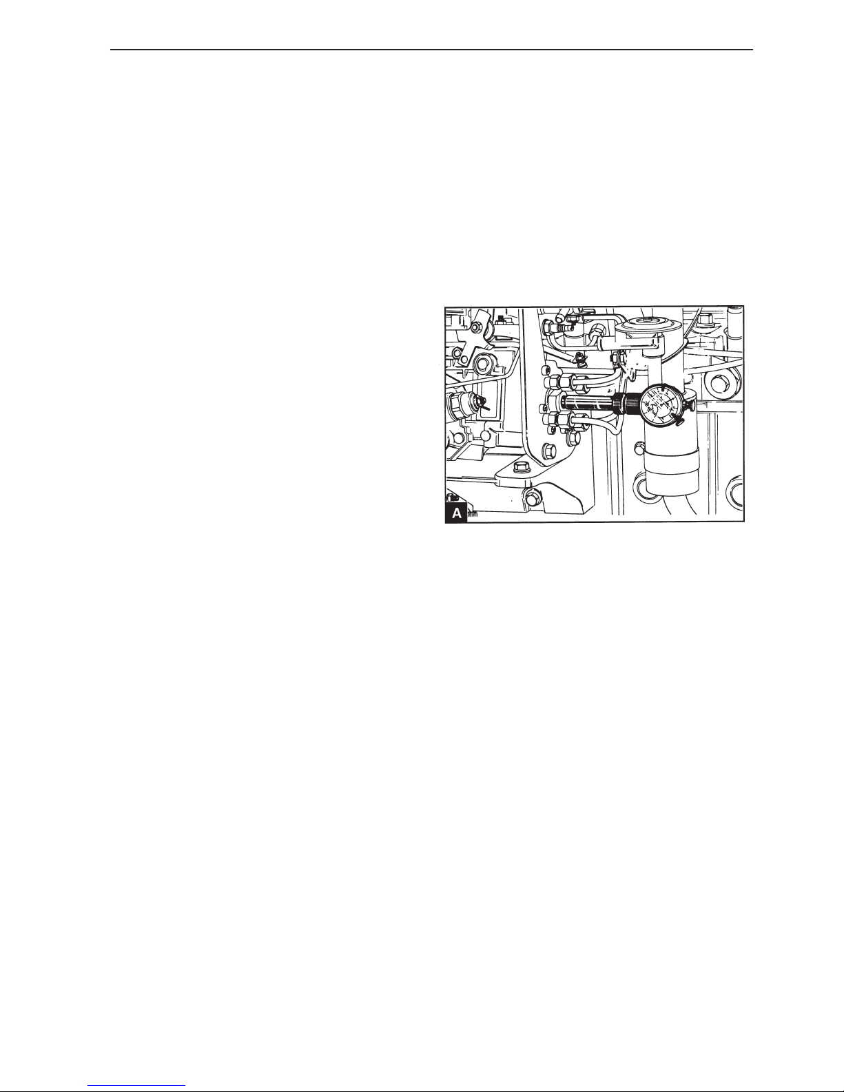
73
Engine settings
8
Check the fuel injection pump adjustment, operations 17A-03.
9
Remove the adjustment drifts and turn the engine
two revolutions to ensure that there is nothing preventing free movement.
10
Install the cap of the timing cover, operation 12A-01
and install the screw in the adjustment hole in the
camshaft cover.
11
Connect the battery.
Injection timing, checking/adjustment (17A-03)
Special tools: 884955, 885139 (TMD22P, TAMD22),
885037
1
Position the piston in cylinder 1 at TDC in the compression stroke, operation 17A-01. Remove the adjustment drifts.
2
Remove the plug and the washer from the center of
the fuel injection pump rear plate and install the
gauge. Set the gauge so that it reads approximately
3.0 mm. Ensure that there is sufficient play between
the gauge and the oil filler pipe, to allow for any radial movement in the pump.
3
Turn the crankshaft slowly (counter-clockwise seen
from the front of the engine) until the gauge displays
the pump element at the bottom of the stroke. Set
the gauge to zero.
4
Slowly turn the crankshaft clockwise, until the adjustment drift goes into the adjustment hole in the
flywheel. In this position the gauge should indicate
the correct lift height for the pump element, see
Workshop Manual “Technical Data”.
Page 76

74
Engine settings
5
If the read out is not within 0.05 mm of the correct
setting, disconnect the fuel delivery lines from the
pump. Use a wrench to prevent the output terminals
on the fuel pump (FP) from moving when the delivery lines are removed or installed. Remove the nuts
for the pump flange and mounting screws for the
rear support bracket.
If the read off value is too low, turn the pump clockwise as seen from the rear, until the correct value
is reached and then tighten the flange nuts and the
screws for the bracket.
If the read off value is too high, turn the pump counter-clockwise as seen from the rear, past the correct setting and then back clockwise to the correct
position. Tighten the flange nuts and the screws for
the bracket.
Remove the adjustment drift from the flywheel and
turn the crankshaft counter-clockwise approximately 45°. Check that the gauge still displays zero and
check the setting again. When the setting is correct,
connect the fuel delivery lines.
6
Remove the gauge and the adapter and reinstall the
plug and the washer. Tighten to 10 Nm.
7
Remove the adjustment drift from the flywheel and
install the adjustment screw in the camshaft cover.
8
Connect the battery.
Page 77
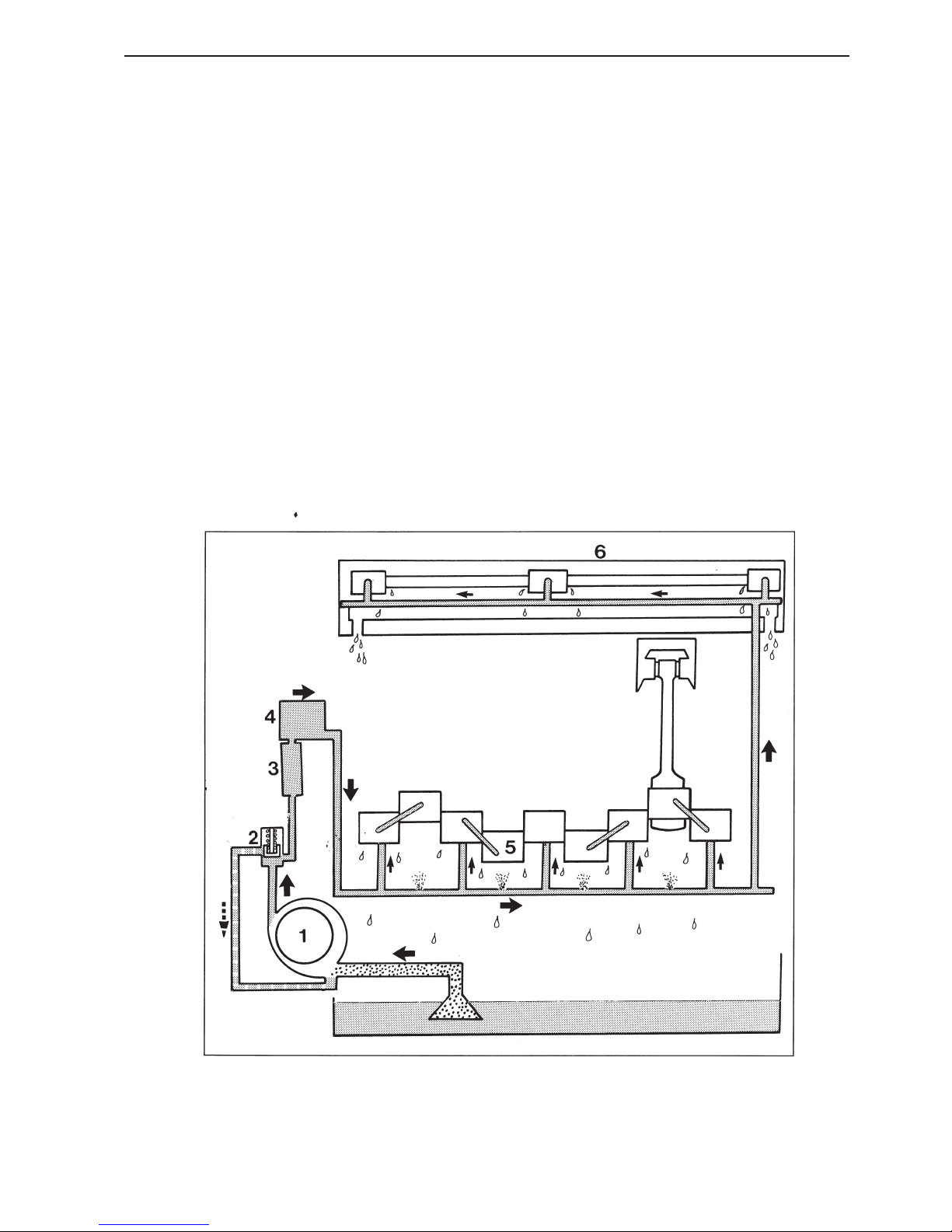
75
Lubrication system
General
The oil pump is located around the front end of the
crankshaft, the pumps inner rotor is driven by a key
in the crankshaft. The pump has an inner and an
outer rotor which are located eccentrically in relation to each other. The inner rotor has ten teeth
which mesh with the outer rotors eleven teeth.
When the pump turns the space between the teeth,
which are meshed with each other, increases so
that a vacuum occurs, or decreases so that pressure increases.
The lubricating oil from the oil pan is routed through
an oil screen and a pipe to a passage in the cylinder
block and from there on to the suction side of the
pump.
A relief valve (mounted in the pump housing) opens
if the pressure is too high. This allows a certain
amount of the oil on the output side to be returned
to the intake side of the pump.
From the pump the oil passes through a filter
mounted on the pump housing. After the filter the oil
passes into the pressure channel which is drilled
the length of the cylinder block.
From the pressure channel the oil passe to the
crankshaft main bearings and through the channels
in the crankshaft to the big ends. The pistons and
the cylinder bores are lubricated by oil mist and
splash lubrication.
Oil passes (through the channels in the block and
cylinder block) from the rear section in the cylinder
block to the pressure channel in the cylinder head.
From the pressure channel in the head the oil passes to each of the camshaft bearing journals. The
valves and the valve lifters are lubricated by oil
mist and splash lubrication.
1. Oil pump
2. Relief valve
3. Oil cooler
4. Oil filter
5. Crankshaft
6. Camshaft
Page 78
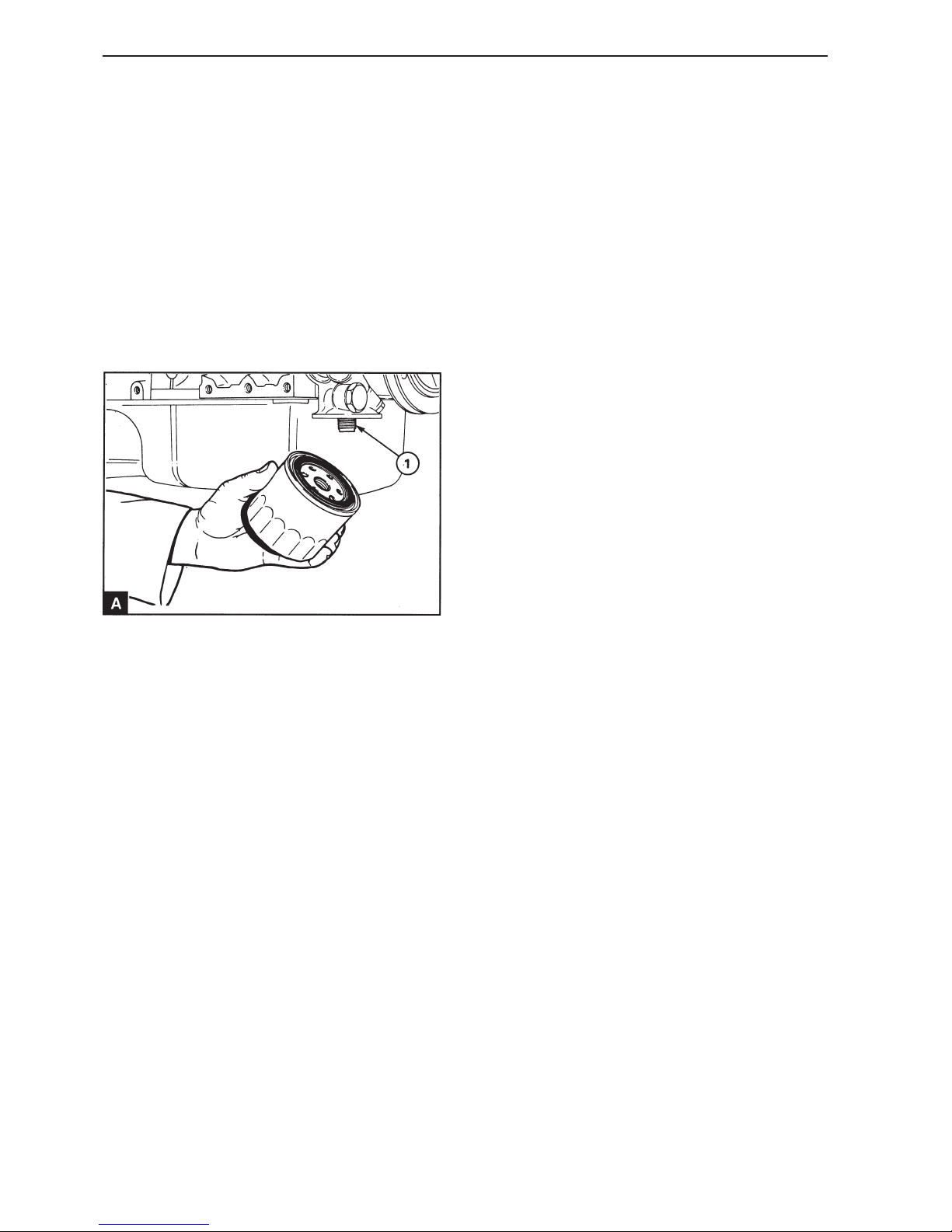
76
Lubrication system
Repair Instructions
Oil filter, replacement (18A-01)
1
Place a container under the filter to collect any
spilled fluid.
2
7
Check that there is lubricating oil in the oil pan.
8
Start the engine and check the filter for leaks.
Check the oil level on the dipstick when the engine
has cooled and top up the oil in the oil pan if necessary.
NOTE! The filter holder contains a valve and a special pipe which ensures that the filter is not drained
of oil. Ensure that the correct type of filter holder is
used.
Remove the filter holder with a strap wrench or a
similar tool. Ensure that the adapter (A1) remains in
the filter head and discard the holder.
3
Clean the filter head.
4
Fill the new reservoir with fresh engine oil. Give the
oil time to fill the holder through the filter element.
5
Lubricate the upper side of the filter holder gasket
with fresh engine oil.
6
Install the new filter holder, hand tighten only. Do
not use a strap wrench.
Oil filter adapter, replacement
(18A-02)
1
Place a container under the filter to collect any
spilled fluid.
2
Remove the oil filter, operation 18A-01.
3
Install the pipe to the oil cooler if required.
4
Unscrew the mounting screws and remove the oil
filter adapter from the oil pump. Discard the gasket.
Page 79
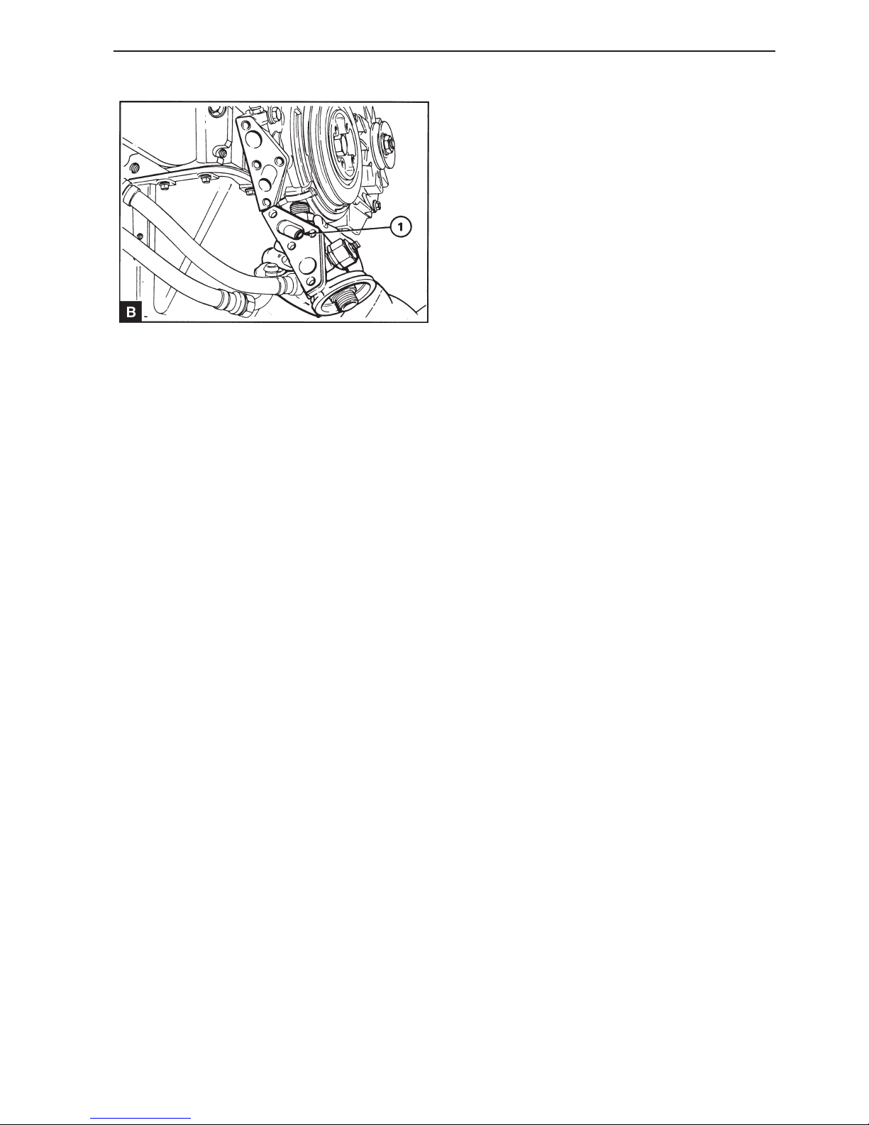
77
Lubrication system
5
Oil pan, replacement (18A-03)
1
Drain the oil. Remove the dip stick. Disconnect the
crankcase ventilation return pipe.
2
Arrange a support for the oil pan if required. Remove the screws holding the oil pan against the cylinder block. Lower the oil pan and remove the gasket.
3
Clean the oil pan with fresh kerosene and ensure
that all kerosene is removed. Clean the flange surfaces on the oil pan and the cylinder block.
4
If the front or rear main bearing caps have been removed, apply sealing compound according to the instructions under point 14 in operation 14A-08.
5
Apply a new oil pan gasket in position on the pan or
the cylinder block. If a two piece gasket is used, apply the sealing compound on the ends of the respective gasket halves and ensure that the ends
are correctly mounted on each other. Install the oil
pan and ensure correct positioning using a mounting
screw on each side. Install the remaining screws
and tighten all the screws to 22 Nm. Install the
drain plug and washer if required and tighten the
plug to 43 Nm.
6
Install the dipstick. Connect the crankcase ventilation return tube.
7
Fill the oil pan to “MAX” level on the dipstick with an
approved engine oil.
Clean the sealing surfaces on the oil filter adapter
and the oil pump.
If an oil cooler is used ensure that a plug is installed
in the oil filter adapter (B1).
6
Install the oil filter adapter with a new gasket
against the oil pump and tighten the mounting
screws to 22 Nm.
7
Connect to the oil cooler pipe and /or the pipe to the
turbocharger if required.
8
Install a new oil filter, operation 18A-01.
Page 80
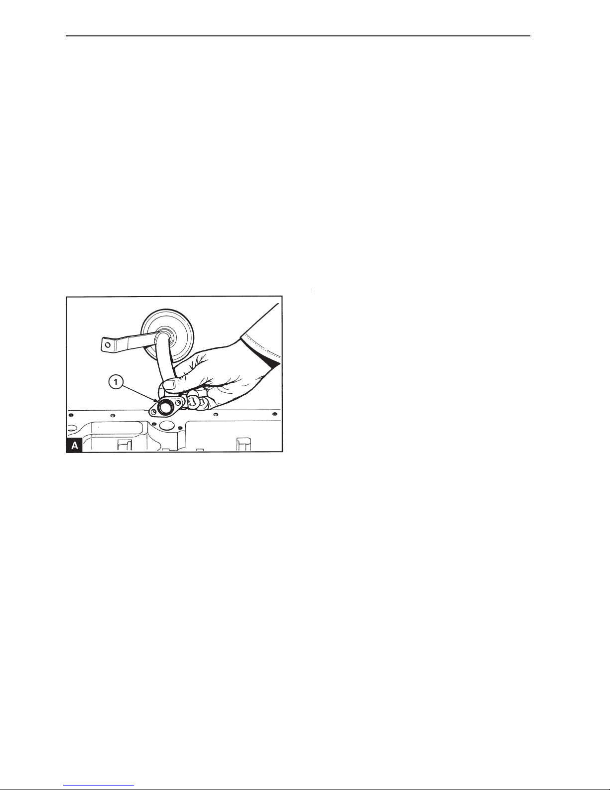
78
Lubrication system
Oil screen and suction pipe,
replacement
(18A-04)
The oil screen is an integrated part of the suction
pipe. No regular service is required, but clean the
oil screen when it is dismantled.
1
Remove the oil pan, operation 18A-03.
2
Remove the screw securing the bracket to the main
bearing cap.
3
Remove the screws at the suction pipe flange and
remove the suction pipe and screen. Remove the
O-ring (A1). Clean the flange surface on the cylinder block and the suction pipe.
4
Install the suction pipe bracket loosely to the correct main bearing cap. Install the suction pipe to the
oil pump with a new O ring. Tighten the screws.
Tighten the mounting screws for the suction pipe
bracket, ensure that the suction pipe is not subjected to tension.
5
Install the oil pan, operation 18A-03 and fill it to
”MAX” on the dipstick with an approved engine oil.
Oil screen and suction pipe,
inspection (18A-05)
1
Clean the unit in kerosene and dry it carefully.
2
Check the pipe, screen and welded joints for cracks
and other damage. Check that the mounting bracket
is well tightened.
3
If a damaged component cannot be welded correctly
the whole unit should be replaced.
Page 81
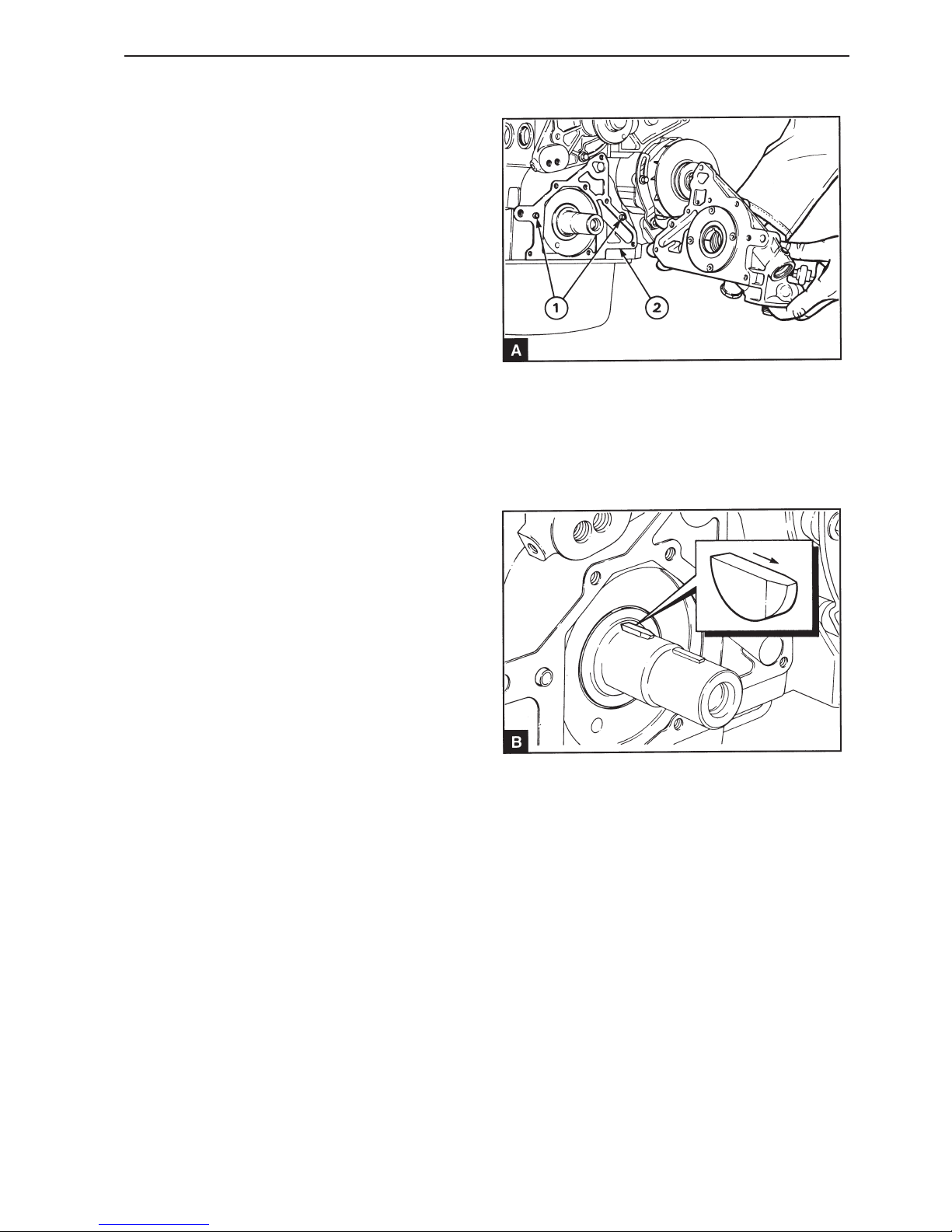
79
Lubrication system
Oil pump, replacement
(18A-06)
Special tools: 885032, 885037
1
Disconnect the battery
2
Remove the screw from the adjustment hole on the
top of the front end of the camshaft cover. Turn the
crankshaft until the adjustment hole in the front of
the camshaft front bearing journal corresponds with
the hole in the cover.
3
Install the adjustment drifts in the camshaft and the
flywheel, see section 17.
4
Remove the generator (GEN) drive belt, operation
22A-03 and remove the water pump pulley.
5
Remove the crankshaft pulley, operation 14A-01A.
6
Remove the cap of the timing cover, operation 15A-
01.
7
Remove the timing belt, pulleys and timing cover,
section 15.
8
Remove the front key in the crankshaft.
9
Unscrew the mounting screws for the oil pump in
stages and evenly and in reverse order to that
shown in the illustration D.
10
Remove the oil pump (A).
11
Check that the mating surfaces of the oil pump, cylinder block and main bearing cap are clean. Check
that the two guide pins (A1) are in position and install a new gasket (A2).
12
Ensure that the rear key is in position and that the
bevelled end of the key is turned forwards (B). If the
front key is still in position, remove it from the
crankshaft.
Page 82
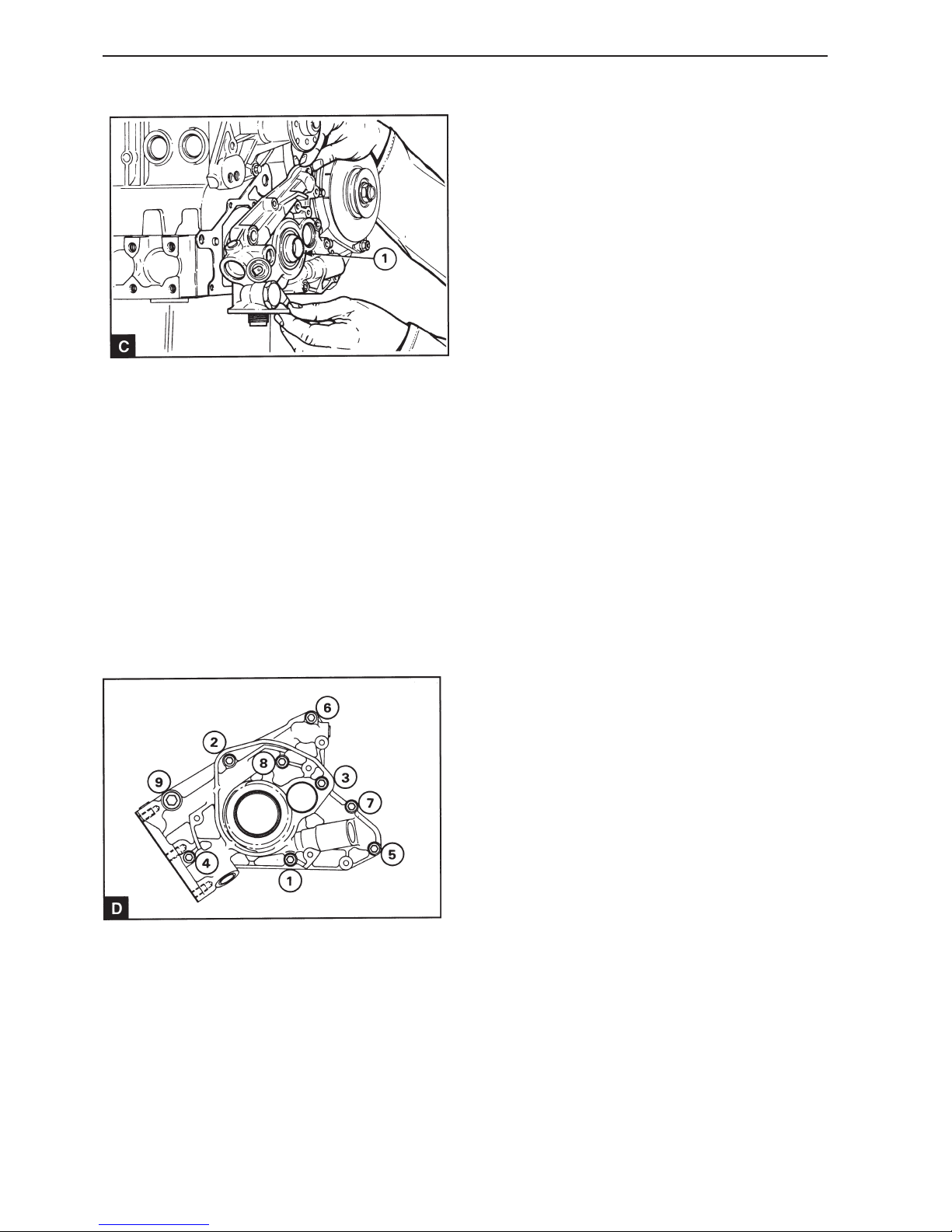
80
Lubrication system
13
Clean the crankshaft and the protective socket
885032-3 and lightly lubricate with fresh engine oil.
Install the protective socket (C1) on the crankshaft.
14
Turn the oil pump rotor until the keygroove in the inner rotor corresponds to the key on the crankshaft.
If the stuffing box is installed in the front end of the
pump, lubricate it lightly with fresh engine oil. Carefully install the pump in position with the keygroove
over the key and with the guide pin inserted in the
pump housing. Remove the protective sleeve.
15
Install the pump mounting screws in position with a
suitable sealing compound applied to the mounting
screw which passes into the main bearing (D1). The
sealing compound is already applied to new mounting screws. Tighten the screws in stages and evenly to the correct tightening torques, see Workshop
Manual “Technical Data”, in the correct order (D).
16
Install the front stuffing box in the pump if necessary, see operation 14A-02.
17
Install a new front key on the crankshaft.
18
Install the timing cover, operation 15A-08.
19
Remove the pulleys and timing belt, see section 15.
Check the fuel injection pump adjustment, opera-
tions 17A-03.
20
Install the cap of the timing cover, operation 15A-
01.
21
Install the crankshaft pulley, operation 14A-01A.
22
Install the pulley for the water pump and the drive
belt for the generator, operation 22A-03.
23
Check that the adjustment drifts have been removed and install the screw in the adjustment hole
on the top of the front of the camshaft cover.
24
Connect the battery.
25
Ensure that the engine cannot be started and turn
the starter motor until the oil pressure gauge reacts
or the oil pressure warning lamp goes out.
26
Start the engine and check for leaks.
Page 83
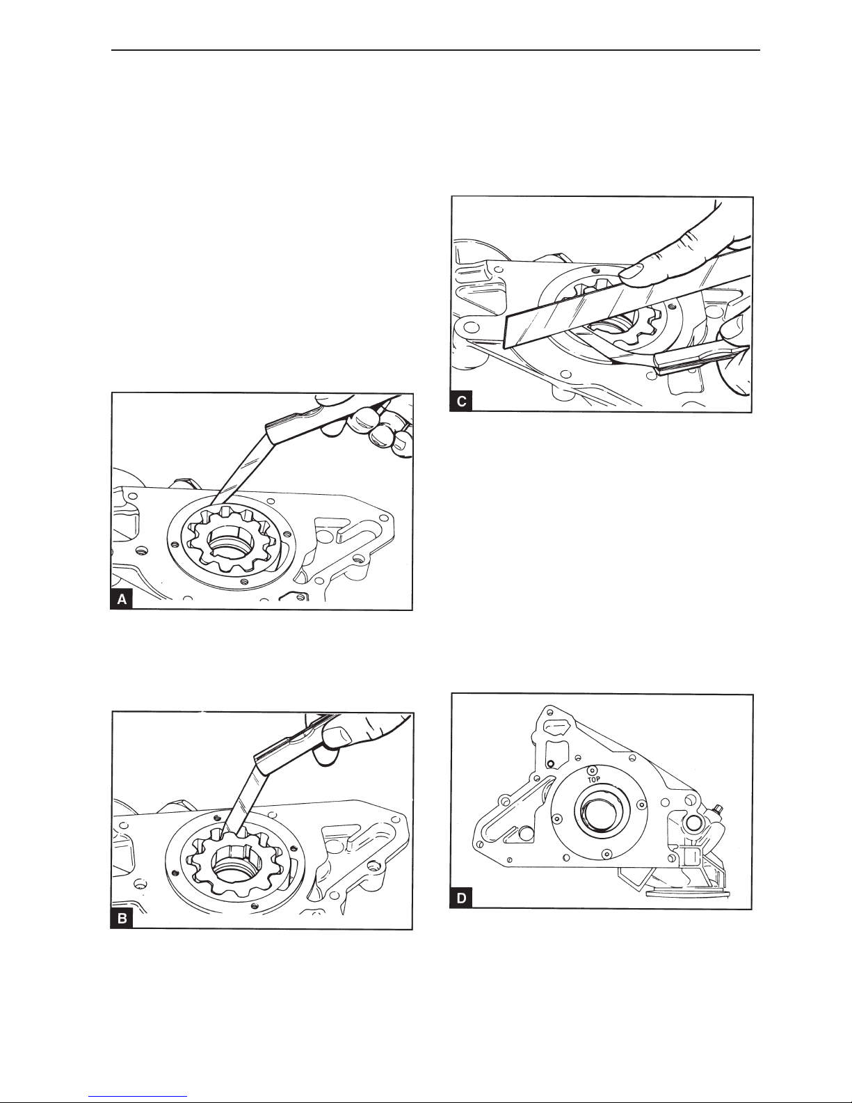
81
Lubrication system
Oil pump, inspection (18A-07)
If the rotors are so damaged that it affects the oil
pump capacity, the whole oil pump must be replaced.
1
Unscrew the screws and remove the oil pump back
plate.
2
Remove the rotors and check the all the components thoroughly. Check for cracks and other damage.
3
Install the rotors in the pump housing and check the
outer rotor play against the housing (A).
4
Check the inner rotor clearance against the outer
rotor (B).
5
Check the rotor axial clearance using a ruler and a
feeler gauge (C). For size and all clearances, see
Workshop Manual “Technical Data”.
6
If the sealing ring needs changing, remove the rotors and press the sealing ring out of the housing.
The pump is easier to install on the engine with the
sealing ring uninstalled and the sealing ring can be
installed on the installed pump, see operation 14A-
02.
If necessary the sealing ring can be installed on the
dismantled pump. Ensure that the sealing lip is
turned in towards the pump and that the sealing is
inserted flat to the pump. Use a suitable adapter
and press in the sealing ring in the pump until the
sealing ring front surface is 0.5 mm lower than the
housing surface.
7
Lightly apply fresh engine oil to the rotors and insert
them in the pump. The inner rotor has a lug in one
end and this tap must be turned towards the sealing
ring housing. Install the back plate with the word
“TOP” turned from the pump housing straight edge
(D). Install and tighten the screws for the back plate
to 4 Nm.
Page 84
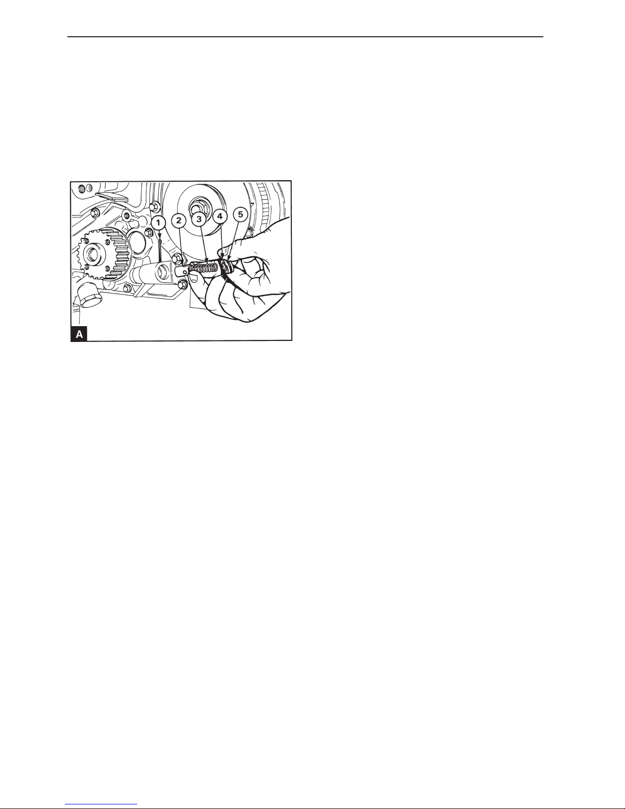
82
Lubrication system
Relief valve, replacement
(18A-08)
The relief valve is installed on the left side of the
pump and can be replaced as a unit. The pressure
setting cannot be adjusted in any other way than by
installing new components.
1
Bend the shafts of the split pin together (A1). Press
the end plug (A4) and remove the split pin from the
pump housing.
2
Take the weight off the plug and if possible remove
the plug and the spring (A3). If the plug will not
come loose, tap it carefully inwards to see if the
spring tension can force it out of the housing. If the
plug still does not come loose, drill a small hole in
the center of the plug, use a self tapping screw to
remove the plug.
3
Remove the spring and piston (A2). A small magnet
can be used to remove the piston.
4
Replace the split pin, the O ring (A5) and the end
plug (if a hole has been drilled in it.)
5
Check that all the components are clean and lubricate them with fresh engine oil. Install a new O ring
on the end plug.
6
Install the piston in the sleeve with the open end of
the piston turned inwards. Install the spring over the
lug on the end of the piston. Install the end plug with
the sprung end inserted in the cutout in the plug.
7
Press in the end plug and install the split pin
through the upper hole in the housing and down
through the lower hole. Bend the split pin shafts
apart.
Relief valve, inspection
(18A-09)
1
Check the spring for wear and other damage and if
possible check what pressure is required to compress a spring to its installed length, see Workshop
manual “Technical Data”.
2
Check the piston for wear and other damage and
check that it travels smoothly in the socket in the
housing.
3
Check the housing and the end plug for wear and
other damage.
4
Replace worn or damaged seals.
Page 85

83
Fuel system
General
All engines are equipped with Bosch fuel injection
pump. These pumps have mechanical engine speed
regulator.
The injectors are supplied with fuel under high pressure from the fuel injection pump and spray the fuel
into the combustion chamber in the form of a finely
misted jet. The pressure under which the injector
operates can be adjusted by replacing the shims
above the spring.
The fuel injection equipment may only be checked
and adjusted by personnel who have the necessary
training.
The supply pump is the membrane type and is mechanically driven. It is mounted on the right side of
the camshaft cover and is driven by an eccentric
cam on the camshaft. The pump is equipped with a
lever for hand pumping.
It is important that no contaminants enter the fuel
system. Before a connector is slackened off, clean
thoroughly around the connector. After a component
has been slackened, position suitable protection
over all open terminals.
Page 86
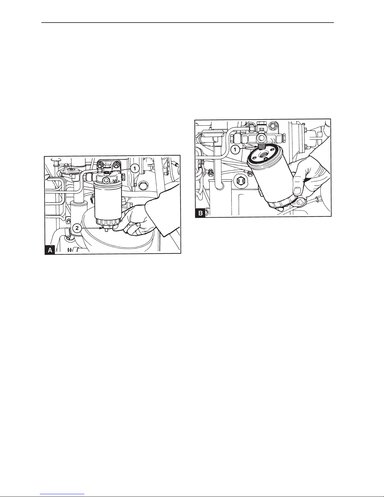
84
Fuel injection system
Repair Instructions
Fuel filter, replacement
(19A-01)
1
Carefully clean the outside of the fuel filter unit.
Slacken off the bleed screw (A1) located above the
filter, two or three turns. Slacken off the drain arrangement (A2) at the bottom of the holder and
drain the fuel into a suitable container.
2
Use a strap wrench or similar to remove the filter
(B).
3
Ensure that the threaded adapter (B1) is steady in
the filter head and that the inside of the head is
clean.
4
Lightly lubricate the new holder top gasket with
fresh fuel. Install the new filter holder onto the filter
head, hand tighten only.
5
Bleed the air from the fuel filter, see operation 19A-
10.
NOTE! It is extremely important that only original
Volvo Penta filter holders are used. Using the wrong
type of holder can damage the fuel injection pump.
Page 87
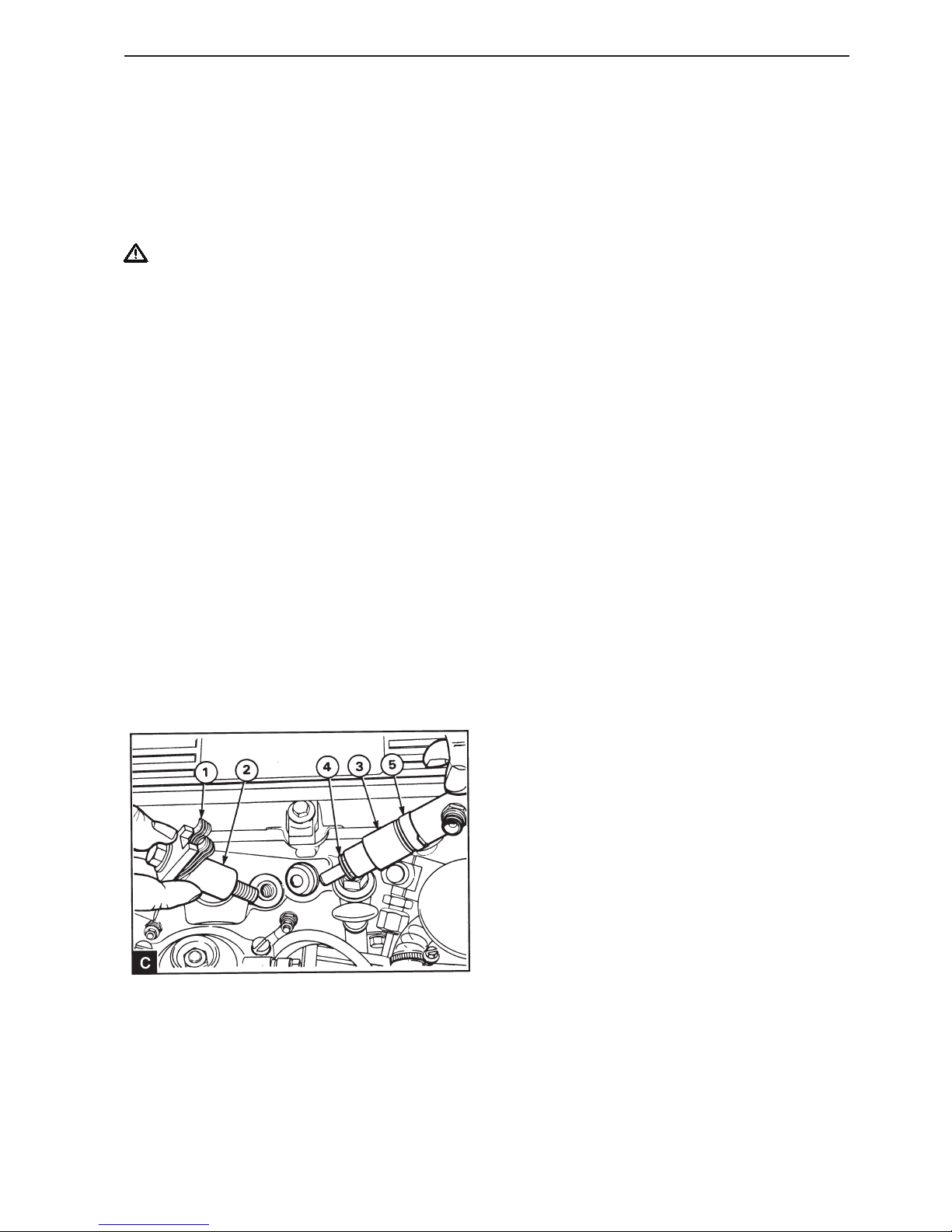
85
Fuel injection system
Injectors, fault-tracing
A faulty injector can cause engine misfires.
To find the faulty injector, run the engine at high
idling speed. Slacken off and tighten the connector
nut for the delivery line for each injector. When the
connector nut for the faulty injector is slackened off
it has little or no effect on the engine speed (RPM).
WARNING! Ensure that fuel is not sprayed
onto your skin.
Injectors, replacement
(19A-02)
1
Remove the leak fuel line.
2
Remove the connector nuts for the delivery lines
from the injectors and from the fuel injection pump.
Hold the pump outlet with a wrench to prevent the
join from moving when the terminal is slackened off.
Do not bend the pipe. Replace the pipe clamps if required.
3
4
Check the holder unit for wear and deformation and
replace the unit if required. Replace the injector
seat gasket.
5
Check that the injector guide ring (C5) is in position
in the cylinder head and install the new injector and
seat gasket. Check that the injector is not crooked.
Install the holder unit and the spacer with holder
arms placed at right angles on the injector’s projection. Tighten the holder mounting screws to 43 Nm.
6
Install the delivery lines and tighten the connector
nuts to 18 Nm. Hold the pump outlet with a wrench
to prevent the join from moving when the nut is
tightened. Install the pipe clamps if required.
7
Install the leak fuel line.
8
Start the engine and check that there are no air and
fuel leaks.
Slacken off the mounting screws for the injector
holders. The spacer piece (C2) should either be
31.5mm or 7 mm long, depending on which type of
injector is used. If a short spacer is used, lift the
spring unit when the mounting screw is removed.
This ensures that the mounting screw threads do
not go in the hole in the lower spring. Remove the
holder (C1) and the spacer washer. Remove the injector (C3) and the seat gasket (A4).
Page 88
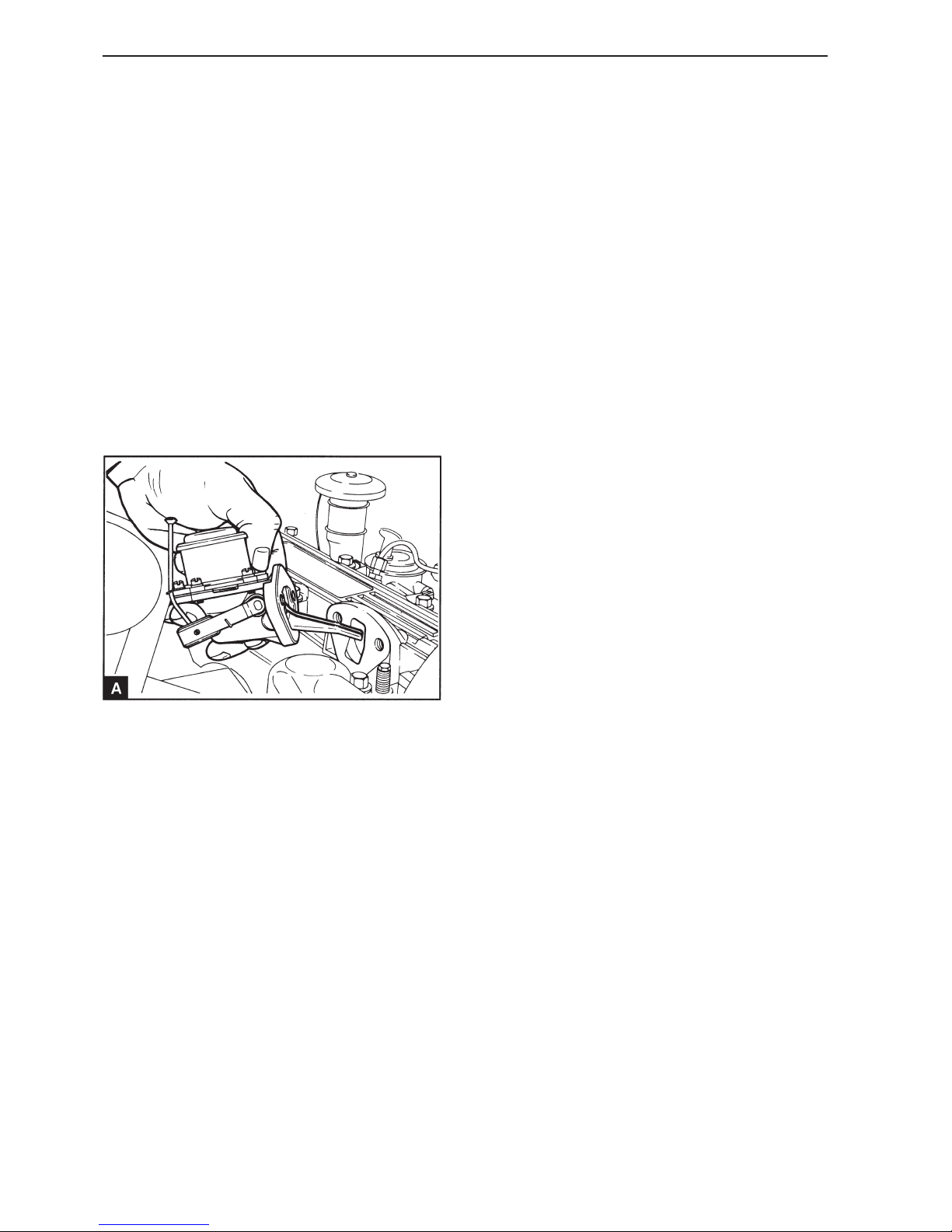
86
Fuel injection system
Feed pump, replacement
(19A-03)
1
Remove the fuel lines from the supply pump.
2
Remove the screw from the adjustment hole on the
top of the front end of the camshaft cover. Turn the
crankshaft until the adjustment hole in the camshaft
front bearing journal corresponds with the hole in
the camshaft cover. This ensures that the highest
point of the eccentric drive cam is turned away from
the pump lever.
3
Unscrew the mounting screws and remove the supply pump (A).
4
Clean the sealing surfaces on the supply pump and
camshaft cover and install the pump with a new
gasket. Install the mounting screws and tighten in
stages and evenly to 22 Nm.
5
Connect the fuel lines.
6
Slacken off the bleed screw in the fuel filter head.
Hand pump with the lever on the supply pump to
eliminate any air between the supply ball and the
fuel filter. Pump with the lever until air free fuel
comes out of the bleed screw. Tighten the bleed
screw.
7
Start the engine and check that there are no air and
fuel leaks.
Page 89
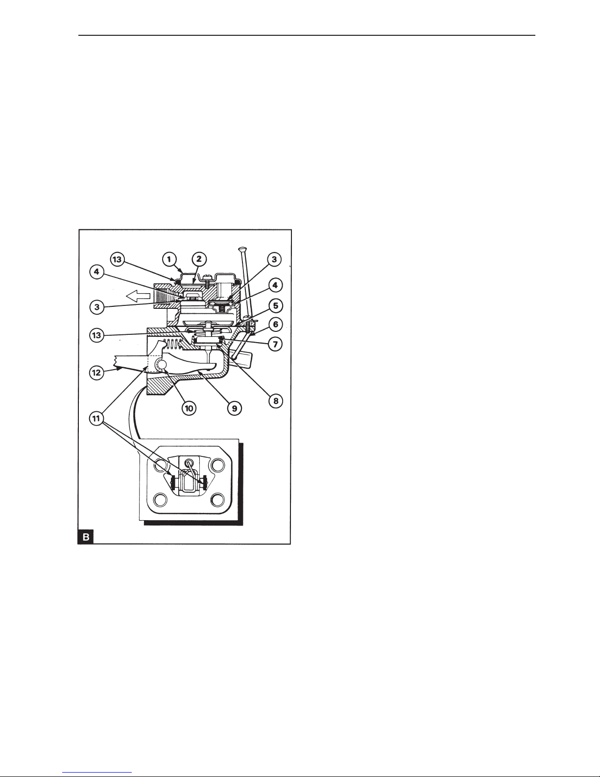
87
Fuel injection system
Feed pump, reconditioning
(19A-04)
1
Clean the outside of the supply pump.
2
Make a mark straight across the flanges on both the
pump halves to ensure correct reinstallation.
3
Remove the cap of the supply pump (B1) and the
metal screen (B2). Remove the screws and separate the pump halves.
4
Turn the diaphragm unit (B5) 90° to remove the diaphragm connecting rod from the control arm (B9)
and remove the diaphragm unit. Remove the shaft
seal (B7), spring seat washer (B8) and the spring
(B13) from the connecting rod. The diaphragm and
the connecting rod unit are replaced as a unit and
service remedies for the diaphragm are not possible.
5
The valves (B4) are jammed in the housing and can
be removed with a suitable jimmy tool. Part of the
flattened metal must be removed before the valves
can be removed.
6
Disconnecting the control arm: secure the rocker
(B12) with a vise and hit the pump housing with a
soft faced hammer to release the two holders (B11).
Take care not to damage the pump housing mating
surface. Remove the rocker arm, the journal (B10),
the control arm and the return spring. Check the
components for wear and other damage.
7
Clean the valve housing thoroughly. Install new seat
washers (B3) and slide the new valves (B4) into position. Because the valves are similar, but one
valve is installed in the opposite direction in relation
to the others, it is possible to install the valves upside down. To ensure that the valves are installed
correctly, follow illustration B. When the valves are
correctly installed flatten the valve housing edge in
six places equally spaced over the perimeter to hold
the valves in position.
8
Place the rocker arm (B12), the journal B10 and the
connecting rod unit (B9) in the lower section of the
supply pump. Install the return spring and check
that the spring ends are in the correct position.
9
Install two new holders (19A.04/B11) in the grooves
in the housing until the lock the journal. Use a light
hammer and a suitable adapter. Flatten the open
ends of the groove to hold the holders in position.
10
Install the diaphragm spring (19A.04/B13) in the
correct position under the diaphragm (19A.04/B5.)
Install the valve seat washer (19A. 04/B8) and a
new shaft seal (19A.04/B7) in position on the connecting rod. Check that the small diameter on the
upper side of the seal is against the round section
of the connecting rod.
Page 90
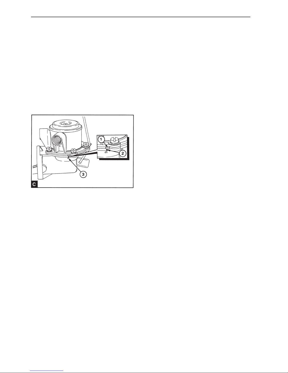
88
11
Install the diaphragm in position above the bottom
pump half with the connecting arm fin upwards towards the slit in the control arm. Ensure that the
small bulge in the edge of the diaphragm (19A.04/
C1) is at a 90° angle to the similar bulge on the
pump housing (19A.04/C2). Press the diaphragm
lightly down until the notch in the connecting rod is
in the slit in the control arm. Turn the diaphragm 90°
to ensure that the bulge on the edge of the diaphragm corresponds with the bulge on the pump
housing. This ensures that the connecting rod goes
into and remains in the slit in the control arm.
12
Press the rocker arm upwards in the diaphragm until the diaphragm lies at the level of the pump housing flange. Install the upper half of the pump housing in position with the marks on the flanges lined
up. Keep pressure on the rocker arm and install the
spring washers and screws. Remove the pressure
from the rocker arm and tighten the screws evenly.
After installation the edge of the membrane should
lie along at the level of the edge of the pump housing.
13
Install the metal screen (19A.04/B2) and the cap
(19A.04/B1) with the rubber seal (19A.04/B14) correctly installed. Install the screw of the cap and
the sealing washer and tighten the screw.
Fuel supply pressure,
checking (19A-05)
If there is fuel leakage through the hole in the pump
housing (19A.04/C3), it means that the diaphragm is
damaged. If there is an oil leakage it means that the
seal is damaged.
1
Remove the outlet pipe for the fuel at the supply
pump. Install a manometer for 0-70 kPa to the output side of the pump. Slacken off the connection of
the gauge and pump the lever by hand to eliminate
air in the line. Tighten the connection when air free
fuel comes out of the line. Check that there is no
leakage at the terminals between the pump and the
manometer.
2
Turn the starter motor for 10 seconds and note the
highest pressure that the manometer displays. The
pump should be repaired or replaced if the displayed pressure is lower than 75% of the minimum
static pressure permitted in production, see Workshop Manual “Technical Data”. Check after the engine has stopped, the time it takes for the pressure
to drop to half the measured value. If the time is
less than 30 seconds the pump should be repaired
or replaced.
3
Remove the manometer and connect the outlet line
to the supply pump. Slacken off the bleed screw on
the fuel filter head and the hand pump until the air
free fuel flows out of the bleed screw. Tighten the
bleed screw.
Fuel injection system
Page 91
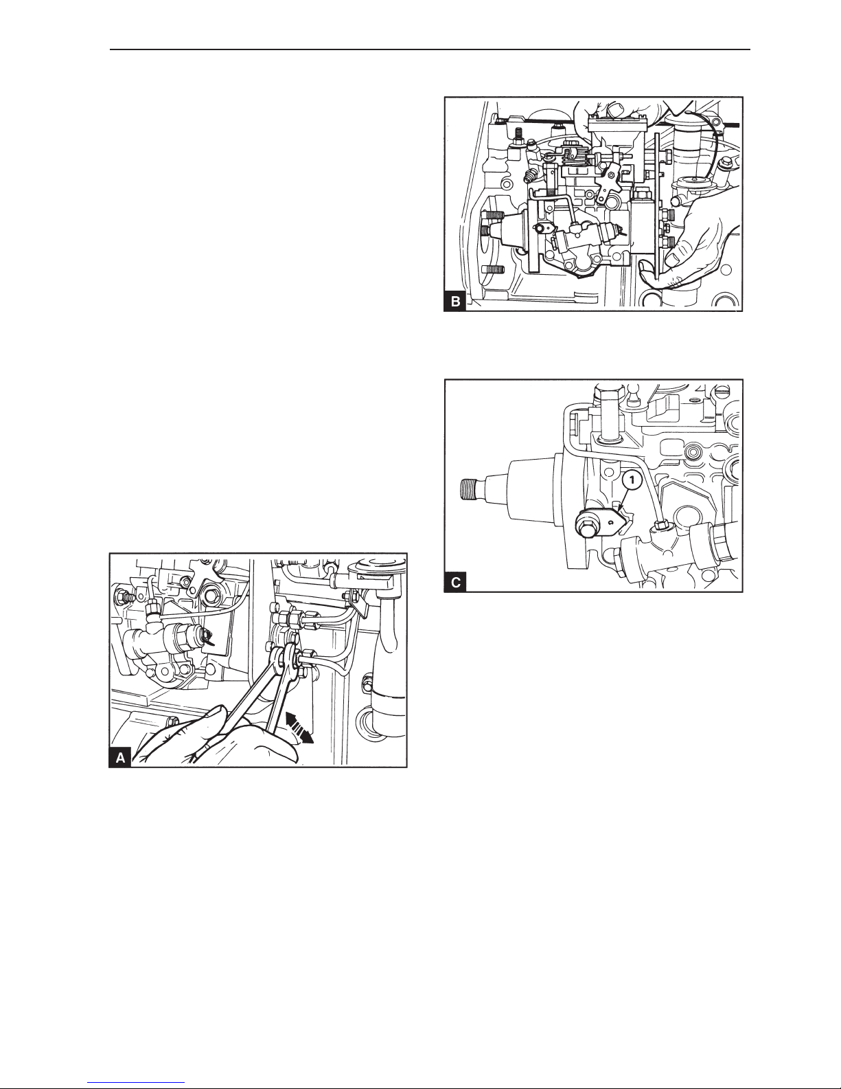
89
Fuel injection system
Fuel injection pump, replacement (19A-06)
Special tools: 885027, 885029, 885037
1
Disconnect the battery.
2
Position the piston in cylinder 1 at TDC in the compression stroke, operation 17A-01 and install the
adjustment drifts 885037.
3
Remove the cap for the timing cover, the timing belt
and the fuel injection pump pulley, see section 15.
4
Disconnect the fuel injection pump engine speed
regulator and, if necessary, the stop control. Detach
the cable from the stop solenoid on the pump. Mark
the cables in a suitable way to facilitate reinstallation.
5
Remove all the necessary pipes from the pump.
Use a wrench as a counterhold at the pump outlets
side (A) to prevent the joint moving when the nuts
for the delivery lines are slackened off.
6
Remove the screws holding the support bracket at
the rear of the pump against the installation bracket.
7
Remove the locknuts and remove the pump (B) –
ensure that the key does not fall out of the drive
shaft.
NOTE! If a new or repaired pump is to be installed,
the pump shaft should be installed in the correct position in relation to the engine with cylinder 1 at top
dead center on the compression stroke. If this is to
happen the spacer in the form of an arrow (C1)
should be removed from its position under mounting
screw, which is located on the pumps front left hand
side. Fasten the spacer to the pump loosely using
metal wire. The pump can be installed and the timing belt tension adjusted with the pump in this condition, but neither the pump shaft nor the crank-
shaft should be turned if the spacer is not in position under the mounting screw.
8
Check that the adjustment drifts are installed in the
camshaft and the flywheel.
Page 92
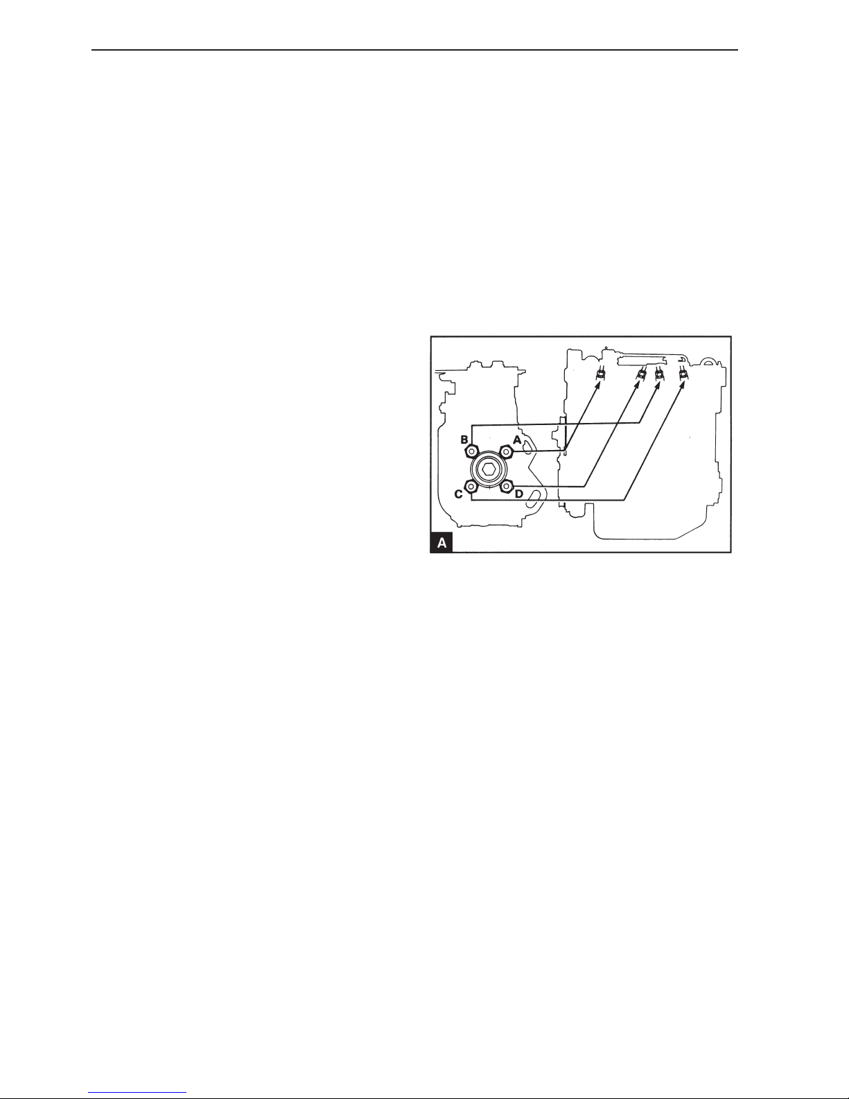
90
Fuel injection system
9
Check that the key is correctly installed on the
pump shaft. Install the fuel injection pump in position with the locknuts sufficiently tightened to hold
the pump secure, but not so much that it prevents
radial movement in the housing. Install the screws
holding the support bracket against the rear end of
the pump and finger tighten them.
10
Install the pulley on the shaft with the key in the
correct keygroove, see operation 15A-05. Hold the
belt so that it does not move and install the pulley
nut and washer. Tighten the nut so that the pulley is
pressed up on the shaft, do not tighten the nut to
the final torque.
11
If the pump shaft is installed in top dead center position (see “Note!” above): Ensure that the tooth
with the correct marking turned towards the arrow
on the timing cover and install the timing belt, see
operation 15A-04. Check the position of the journals
in the cut out in the pump mounting flange. Check
that the fuel injection pump can be turned clockwise
seen from the rear when the belt tension is adjusted. If there is not sufficient room for movement
change the position of the belt on the pulley. Adjust
the timing belt tension, operation 15A-03. Check
that the journals are not in the end of the groove in
the pump mounting flange and tighten the locknuts.
Unscrew the mounting screw on the side of the
pump and install the spacer under the screw.
Tighten the mounting screw to 12 Nm. Tighten the
nut for pump pulley to 60 Nm. Check the fuel injection pump adjustment, operations 17A-03.
If the pump shaft is not secure: Ensure that the
tooth with the correct marking turned towards the
arrow on the timing cover and install the adjustment
drifts through the smooth holes in the pump pulley.
Install the timing belt, see operation 15A-04 and remove the adjustment drifts. Adjust the belt tension,
operation 15A-03. Tighten the nut for pump pulley to
60 Nm. Adjust the pump setting, operation 17A-03
and tighten the pump flanged nuts.
12
Tighten the screws holding the support bracket at
the rear of the pump against the installation bracket.
13
Check that the adjustment drifts are removed.
14
Install the cap of the timing cover, operation 15A-
01.
15
Install the low pressure lines. Certain pumps have a
banjo screw, which is marked “OUT” and this must
be installed at the fuel return connection at the tank.
16
Install the delivery pipes to the pump. Use a wrench
to prevent the output terminals on the fuel pump
(FP) from moving when the delivery lines are installed. The connections to the pump are as displayed in illustration A. Do not tighten the connector
to the injectors until the system has been bled.
17
Connect the engine speed regulator to the fuel
pump (FP) and connect the stop control if required.
Connect the cables for the stop solenoid on the
pump. Connect the battery.
18
Bleed the fuel injection system, operation 19A-08.
Page 93
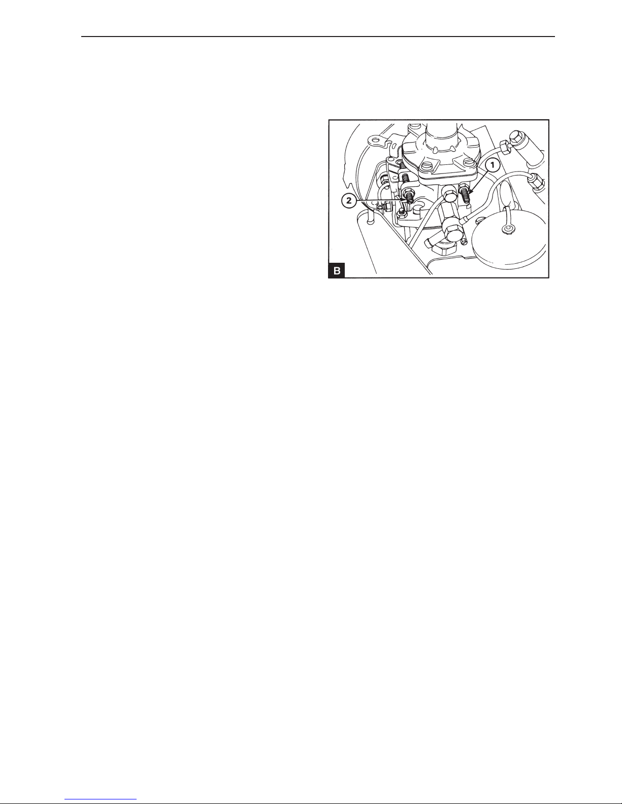
91
Fuel injection system
19
Run the engine and check for any leakage. Check
that the idle speed is correct, operation 19A-07.
20
If a new fuel injection pump has been installed,
check that maximum idling speed, operation 19A-
07.
Idling speed, adjustment
(19A-07)
1
Run the engine to operating temperature and check
the idling speed. If required adjustment can be carried out using the inner adjustment screw (B1).
Slacken off the locknut and turn the screw clockwise to increase and counter-clockwise to decrease
the engine speed (RPM). Tighten the locknut when
the engine speed (RPM) is correct.
2
Check the maximum idling speed with the engine at
operating temperature. The maximum idling speed
is taken from the last section of the fuel injection
pump setting code. The setting code can be found
on the type plate on the side of the fuel injection
pump. A typical setting code is 2643H000CE/1/
3200. In this example the maximum idle speed is
3200 rpm. If necessary this speed can be adjusted
with the outer adjuster screw (B2). Slacken off the
locknut and turn the screw counter-clockwise to increase and clockwise to decrease the engine speed
(RPM). When the engine speed (RPM) is correct,
tighten the locknut and seal the screw. The person
who installs the pump must check that the adjustment screw is sealed in a suitable manner so that
the setting cannot be changed later.
On new pumps the adjustment screw is set and
sealed by the manufacturer. The setting may not be
changed, if it is changed the engine’s guarantee can
be affected.
Page 94
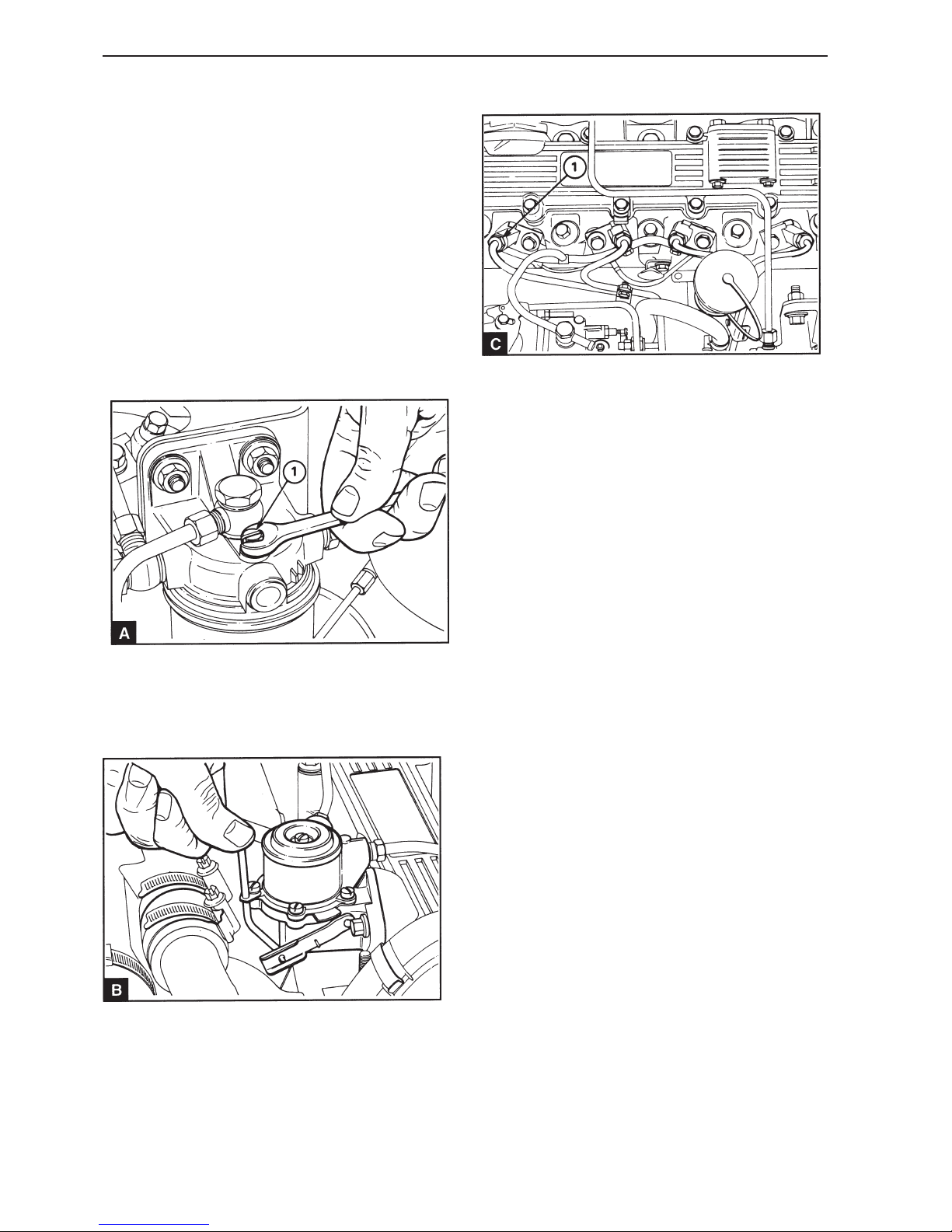
92
Fuel injection system
Fuel injection system, bleeding
(19A-08)
If air has entered the fuel injection system it must
be removed before the engine is started.
Air can enter the fuel injection system if:
• The fuel tank is run dry during normal operation.
• The low pressure fuel lines are loosened.
• Any section of the low pressure system leaks
while in operation.
Carry out the following to bleed the system:
1
Slacken off the bleed screw (A1) located above the
fuel filter, two or three turns.
2
3
Slacken off the connector nuts for the delivery lines
at the injectors (C). Depending on the type of injectors the connector nuts can be located above or beside the injectors.
4
Operate the starter motor until air free fuel is forced
out of the delivery line connectors. If a separate
switch is used for the starter motor, ensure that the
switch for the engine electrical system is in the
“ON” position at this moment.
5
Tighten the delivery lines connections.
6
The engine is now ready to be started.
If the engine runs as it should for a short period of
time and then stops or runs unevenly, check if there
is air in the fuel system. If there is air in the fuel
system, there is probably a leak in the low-pressure
side of the system.
Pump the supply pump (B) with the lever until air
free fuel comes out of the bleed screw. Tighten the
bleed screw on the filter. If the supply pump drive
cam is in position for maximum cam lift it is not
possible to pump by hand. In this situation the
crankshaft must be turned one revolution.
Page 95
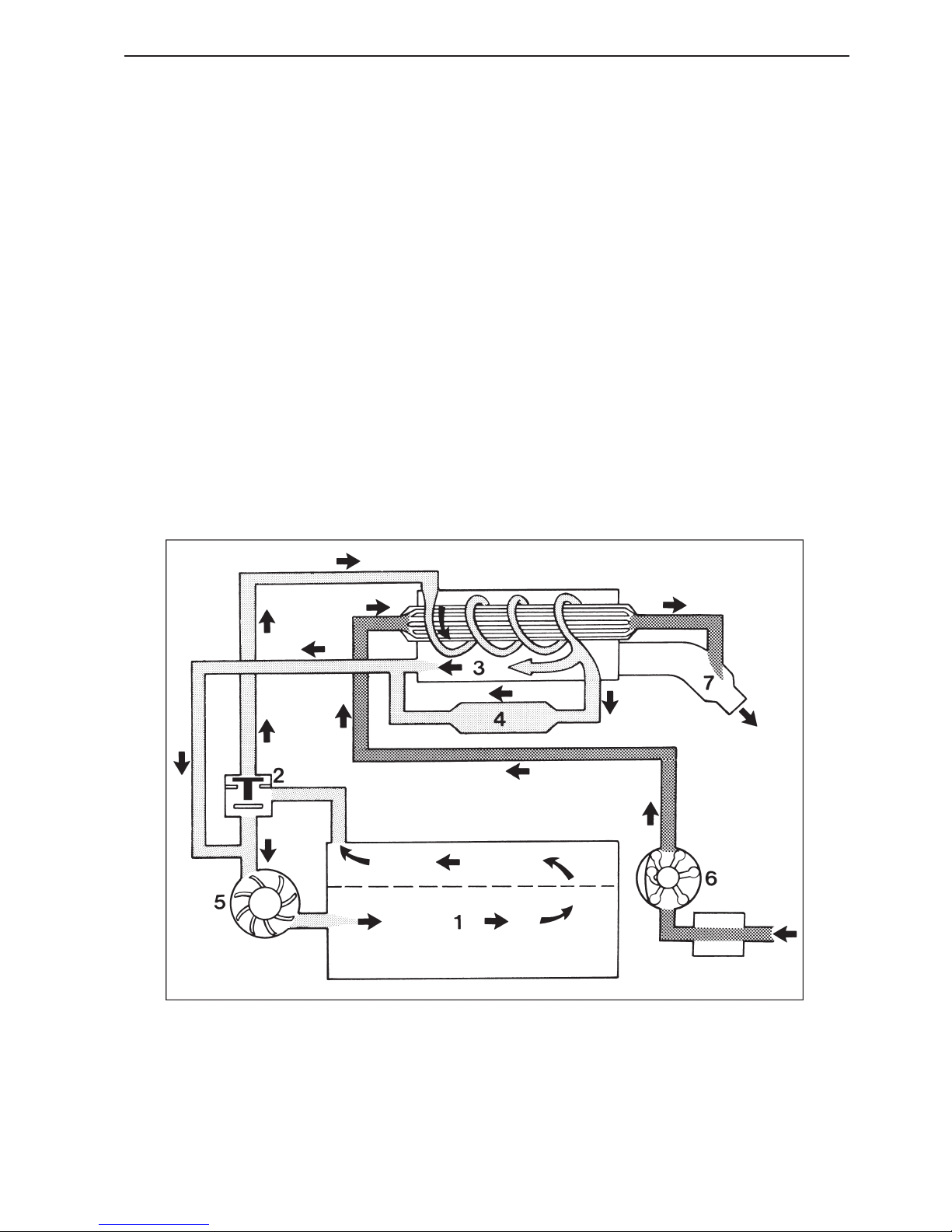
93
Cooling system
General
The engine has two cooling circuits. The closed circuit is filled with coolant which is used for cooling
the cylinder block and cylinder head. This coolant is
also used to cool the exhaust manifold. The sea water circuit uses sea water, which is drawn directly
from the outside of the boat, to cool the coolant in
the closed circuit and to cool the engine oil (only Aengines).
The heat exchanger, exhaust manifold and coolant
tank for the coolant in the closed circuit are combined in one unit. This is installed on the right of the
engine. On B-engines the oil cooler is also built into
the heat exchanger (MD22L-B has no oil cooler).
The coolant in the closed circuit passes from the
coolant tank to the intake side of the pump. From
the pump the coolant passes through the cylinder
block and cylinder head to the thermostat housing.
If the coolant is cold, it passes through the by-pass
connection directly to the intake side of the pump.
When the coolant temperature increases, the thermostat valve opens, the by-pass connection closes
and the coolant passes through the heat exchanger.
In the heat exchanger the coolant passes along the
outside of the pipes and is cooled by the sea water
in the pipes. The coolant then leaves the heat exchanger and enters the tank unit, where it cools the
exhaust manifold which forms an integral part of the
unit. The coolant then moves to the intake side of
the water pump. Some of the coolant passes
through an outlet in the rear of the unit to an oil
cooler and then to the intake side of the pump (only
A-engines).
The sea water is circulated by the sea water pump
which is directly driven from the rear end of the
camshaft on A-engines and belt-driven from the rear
end of the camshaft on B-engines. From the pump
the sea water passes through the heat exchanger
pipes and is then expelled through the outlet.
Outline diagram MD22A, MD22L-A, TMD22A
4. Engine oil cooler
5. Freshwater pump
6. Sea water pump
7. Outlet bend
1. Cylinder block
2. Thermostat
3. The combined coolant tank, heat exchanger and exhaust manifold
Page 96
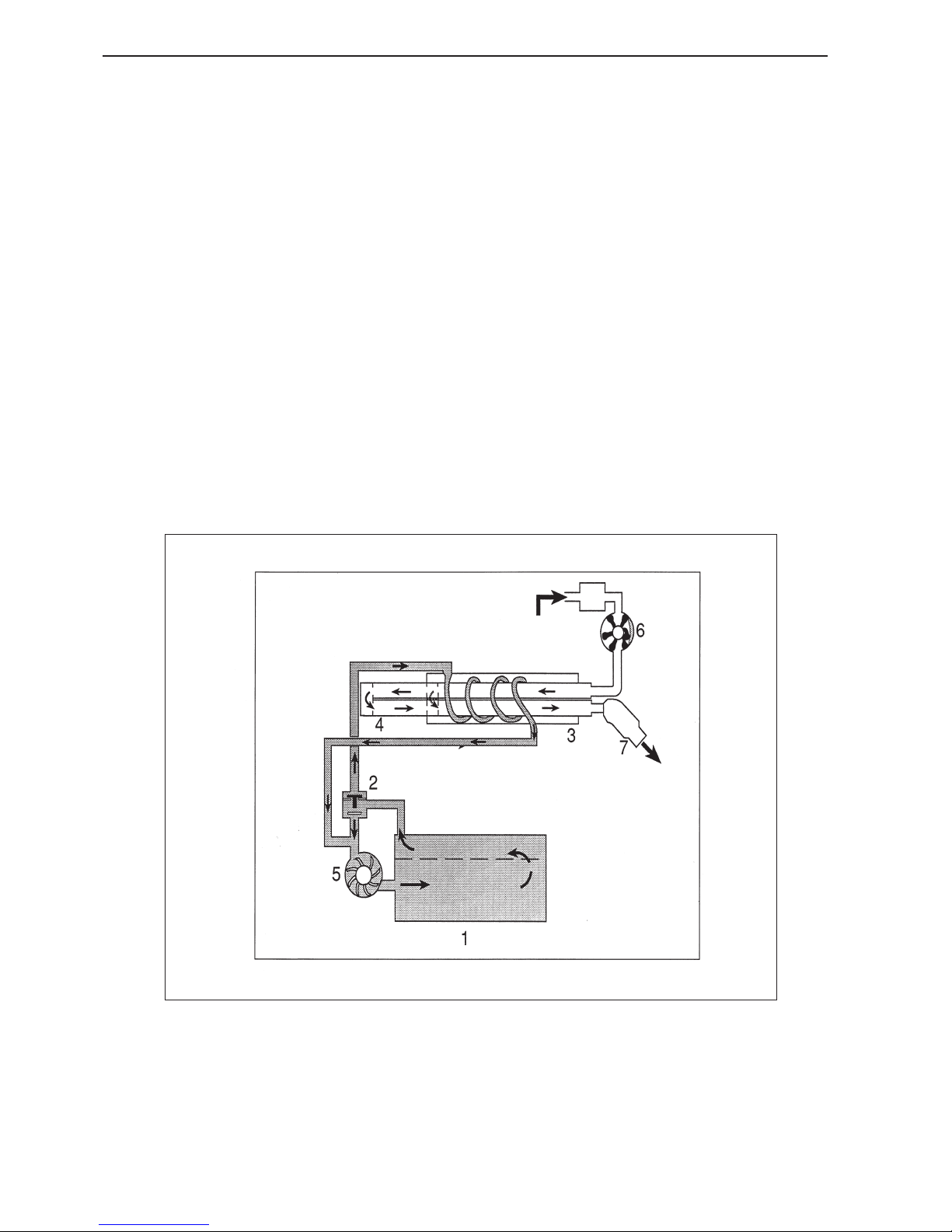
94
Cooling system
MD22L-B, MD22P-B, TMD22-B, TMD22P-C, TAMD22P-B
5. Freshwater pump
6. Sea water pump
7. Outlet bend
8. Charge air cooler (only TAMD22)
1. Cylinder block
2. Thermostat
3. The combined coolant tank, heat exchanger
and exhaust manifold
4. Engine oil cooler (MD22P, TMD22, TAMD22)
Page 97
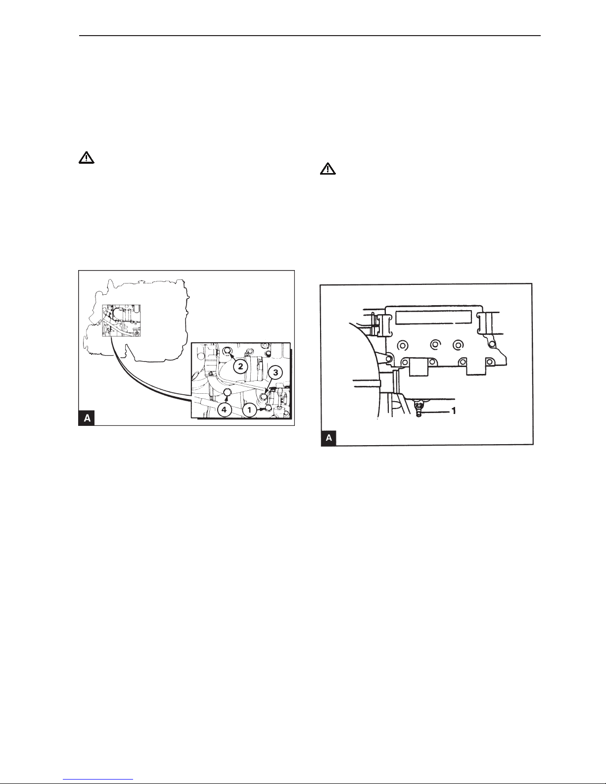
95
Cooling system
Repair Instructions
Coolant, draining (20A-01)
Applies to MD22L-B, MD22P-B, TMD22-B,
TMD22P-C, TAMD22P-B
WARNING! Do not drain coolant when the en-
gine is still warm and the system is pressurized, as dangerous hot coolant may spray out.
1
Remove the coolant tank filler cap.
2
Drain the coolant using the cock (A1) on the starboard side of the engine block.
3
Install the drain plug and the filler cap.
4
Place a suitable label on the engine control panel
stating that the coolant has been drained.
Coolant, draining (20A-01)
Applies to MD22A, MD22L-A, TMD22A
WARNING! Do not drain coolant when the en-
gine is still warm and the system is pressurized, as dangerous hot coolant may spray out.
1
Remove the coolant tank filler cap.
2
Drain the coolant by removing the plug (A1) on the
starboard side of the engine block. Ensure that the
drain hole is not blocked by contaminants.
3
Drain the heat exchanger / manifold / coolant tank
assembly by removing the drain plug (A2). Ensure
that the drain hole is not blocked by contaminants.
4
Drain the oil cooler by opening the drain plug (A3).
Ensure that the drain hole is not blocked by contaminants.
5
Install the drain plugs and the filler cap.
6
Place a suitable label on the engine control panel
stating that the coolant has been drained.
Page 98
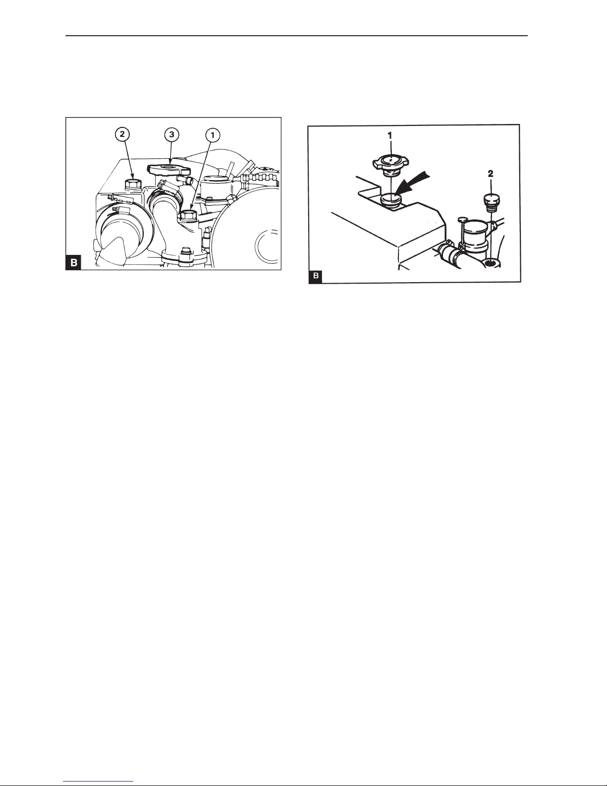
96
Cooling system
Remove the bleed plug from the hot water connection (B1) or the plug (B2) on the heat exchanger.
2
Remove the filler cap (B3) from the coolant tank
and fill the tank with coolant to the level of the filler
pipe.
3
Install the ventilation plug and the filler cap.
4
Start the engine. Stop it when it has reached normal
operating temperature and let it cool.
5
Remove the filler cap from the coolant tank and fill
with coolant to the level of the filler pipe. Install the
filler cap.
NOTE! If the circuit is topped up with coolant, it
must have the same composition as the coolant already being used in the system.
Coolant, filling (20A-2)
Applies to MD22A, MD22L-A, TMD22A
1
Coolant, filling (20A-2)
Applies to MD22L-B, MD22P-B, TMD22-B,
TMD22P-C, TAMD22P-B
1
Remove the bleed plug from the outlet connection
for the coolant (B2).
2
Remove the filler cap (B1) from the coolant tank
and fill the tank with coolant to the level of the filler
pipe.
3
Install the ventilation plug and the filler cap.
4
Start the engine. Stop it when it has reached normal
operating temperature and let it cool.
5
Remove the filler cap from the coolant tank and fill
with coolant to the level of the filler pipe. Install the
filler cap.
NOTE! If the circuit is topped up with coolant, it
must have the same composition as the coolant already being used in the system.
Page 99
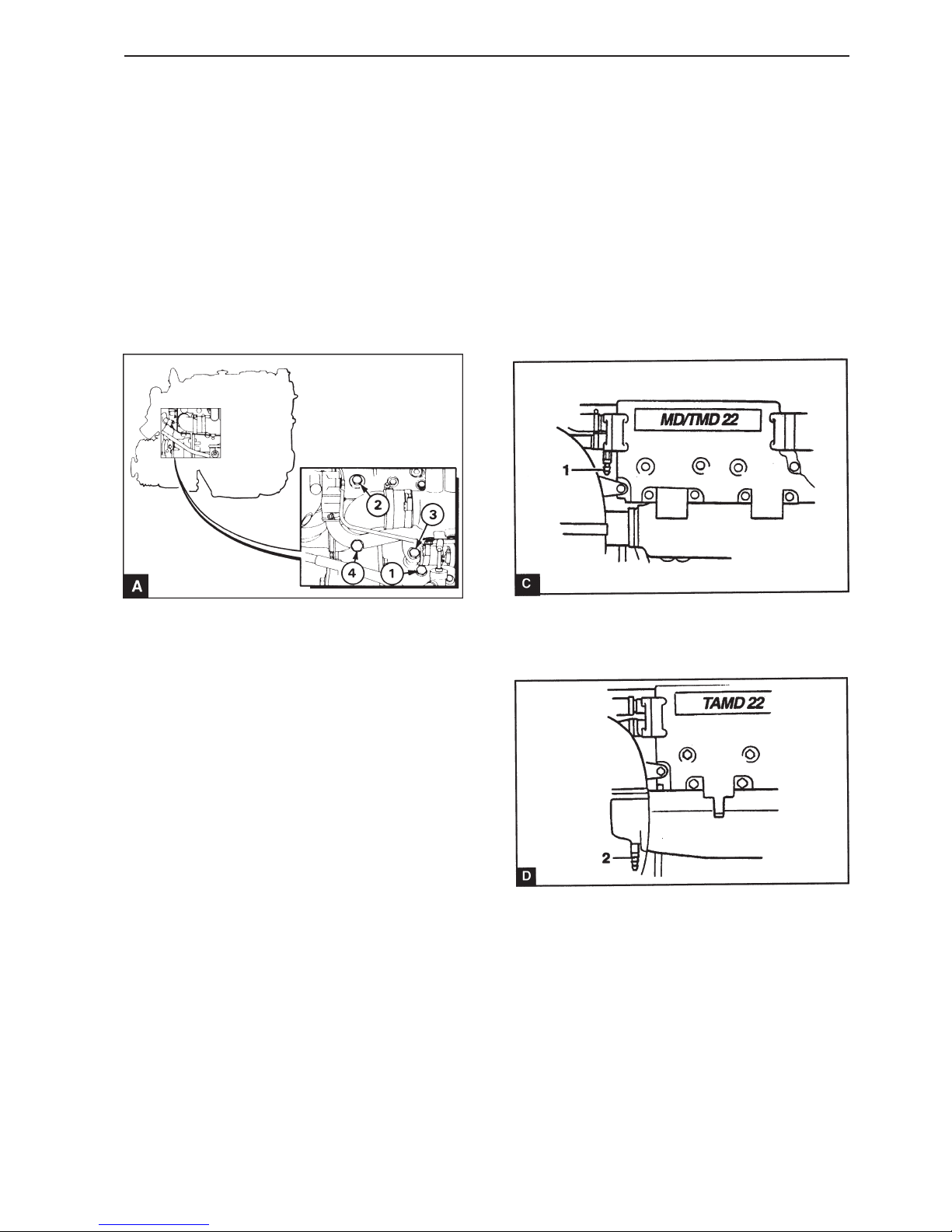
97
Cooling system
Sea water circuit, draining
(20A-03)
Applies to MD22A, MD22L-A, TMD22A
1
Check that the seacock is closed.
2
Disconnect both hoses from the sea water pump.
3
Drain the water from the heat exchanger through the
cock (A4). Ensure that the drain hole is not blocked
by contaminants.
4
Turn over the engine to check that the sea water
pump is empty.
5
Connect the hoses and close the cock.
Sea water circuit, draining
(20A-03)
Applies to MD22L-B, MD22P-B, TMD22-B,
TMD22P-C, TAMD22P-B
1
Check that the seacock is closed.
2
Disconnect both hoses from the sea water pump.
3
Drain the water from the heat exchanger (MD, TMD)
through the cock (C1).
On the TAMD22 the water is drained through the
cock (D2) on the charge air cooler (CAC).
4
Turn over the engine to check that the sea water
pump is empty.
5
Connect the hoses and close the cock.
Page 100
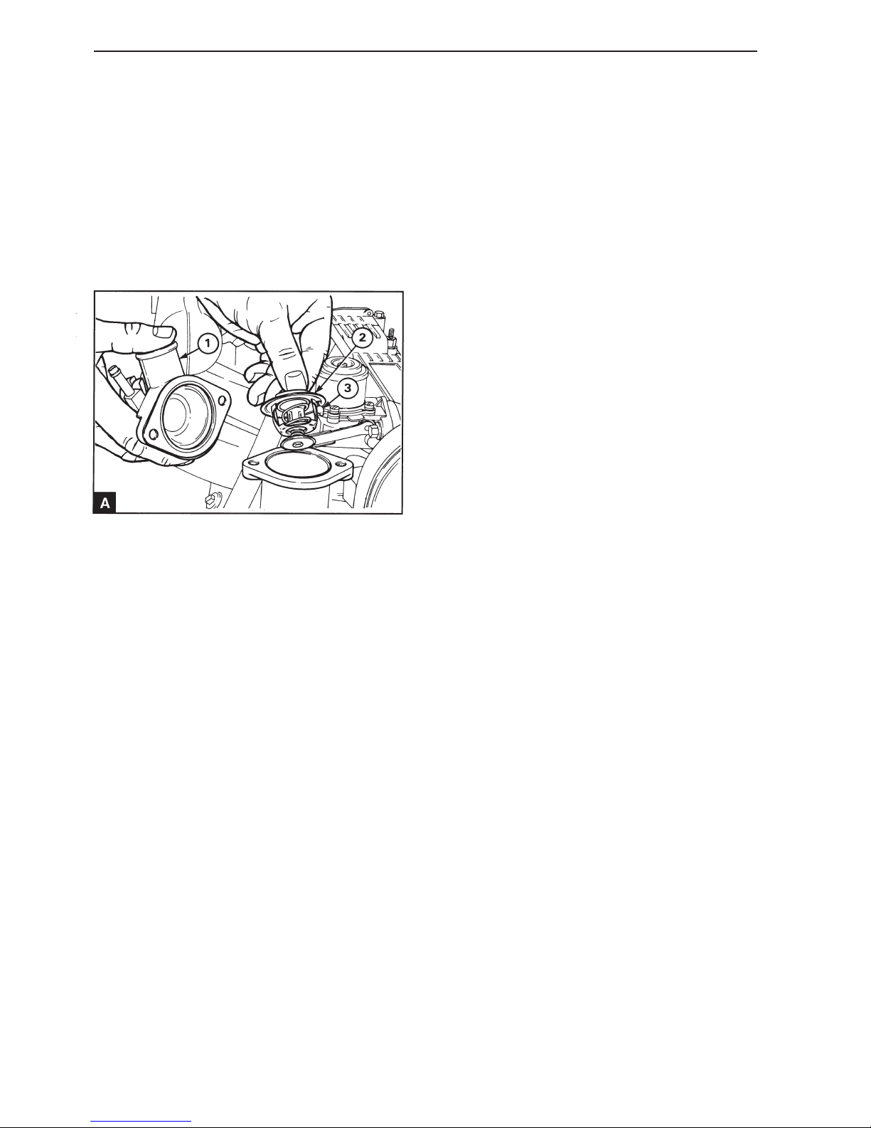
98
Cooling system
Thermostat, replacement
(20A-04)
1
Drain the cooing system so that the coolant level is
below the position of the thermostat and disconnect
the upper hose from the coolant outlet connection.
2
Remove the mounting screws and remove the coolant outlet connection (A1).
3
Remove the thermostat (A2).
4
Check that the sealing surfaces of the housing and
the outlet are clean and the tilt pin (A3) in the thermostat can move freely.
5
Install the new thermostat in position in the housing.
6
Install the coolant outlet connection for the with a
new gasket and tighten the mounting screws.
7
Connect the upper hose and fill the coolant system
with the correct coolant, see the relevant manual.
Thermostat, checking
1
Suspend the thermostat in a suitable container filled
with water.
2
Warm the water slowly. Use a thermometer to
measure at what water temperature the thermostat
starts to open and at what temperature it is fully
open. For the correct temperatures see Workshop
Manual “Technical data”.
3
If the thermostat does not operate correctly, it must
be replaced. Do not try to change the setting.
.
 Loading...