

Volvo Penta TAD940GE, TAD941VE, TAD941GE, TAD940VE, TAD943VE Workshop Manual
...
Workshop Manual
Group 20 Technical Data
TAD940GE, TAD941GE
TAD940VE, TAD941VE, TAD942VE, TAD943VE
TAD950VE, TAD951VE, TAD952VE
I
1(0)

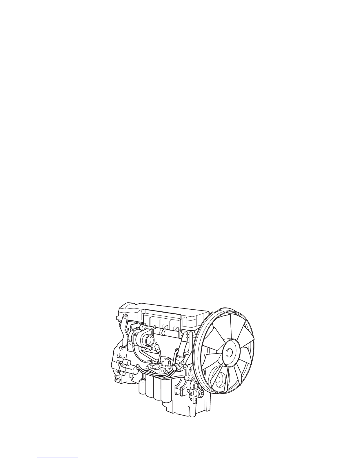
Technical data
Industrial Engines
TAD940GE, TAD941GE
TAD940VE, TAD941VE, TAD942VE, TAD943VE
TAD950VE, TAD951VE, TAD952VE
Contents
Safety information ................................................ 2
General information ............................................. 5
Technical data ...................................................... 6
General ............................................................... 6
Engine ................................................................ 8
Valve mechanism ............................................... 10
Timing gear ......................................................... 14
Reciprocating components .................................. 16
Lubrication and oil systems................................. 19
Fuel system ........................................................ 22
Inlet and exhaust system .................................... 23
Cooling system ................................................... 24
Engine control system ........................................ 25
Tightening torque ................................................ 27
References to Service Bulletins .......................... 36
Group 20
Safety information
This workshop manual contains technical data, descriptions and repair instructions for the Volvo Penta
products or product versions noted in the table of contents. Make sure that you use the correct workshop
literature.
Important
The following special warning signs are used in the
workshop manual and on the product.
WARNING! Warns for the risk of personal injury,
major damage to product or property, or serious
malfunctions if the instruction is ignored.
IMPORTANT! Is used to call attention to things
which could cause damage or malfunctions to
product or property.
NOTE! Is used to call attention to important informa-
tion, to facilitate work processes or operation.
To give you a perspective on the risks which always
need to be observed and precautions which always
have to be taken, we have noted them below.
Make it impossible to start the engine by cutting
system current with the main switch(es) and
lock it (them) in the off position before starting
service work. Fix a warning sign by the control
station.
All service work should normally be done on a
stationary engine. Some work, such as adjustments, need the engine to be running, however.
Going close to a running engine is a safety risk.
Remember that loose clothes, long hair etc. can
catch on rotating components and cause severe
injury.
If work is done adjacent to a running engine, a
careless movement or a dropped tool can lead
to personal injury in the worst case. Take care
to avoid contact with hot surfaces (exhaust
pipes, turbocharger, charge air pipe, starter
heater etc.) and hot fluids in pipes and hoses in
an engine which is running or has just been
stopped. Reinstall all protective parts removed
during service operations before starting the engine.
Read the available safety information, ”General information” and ”Repair instructions” in the workshop manual before you start to do any service
work.
Check that the warning or information labels on
the product are always clearly visible. Replace
labels which have been damaged or painted
over.
Never start the engine without installing the air
cleaner (ACL) filter. The rotating compressor turbine in the turbocharger can cause severe injury. Foreign objects entering the intake ducts can
also cause mechanical damage.
Never use start spray or similar products as a
starting aid. They may cause an explosion in
the inlet manifold. Danger of personal injury.
Only start the engine in a well- ventilated area.
When operated in a confined space, exhaust
fumes and crankcase gases must be ventilated
from the engine bay or workshop area.
Avoid opening the coolant filling cap when the
engine is hot. Steam or hot coolant can spray
out and the system pressure will be lost. When
needed, open the filler cap slowly and release
the pressure in the system. Be extremely careful if a tap, plug or coolant hose has to be removed from a hot engine. It is difficult to anticipate in which direction steam or hot coolant can
spray out.
Hot oil can cause burns. Avoid skin contact with
hot oil. Ensure that the lubrication system is not
under pressure before carrying out any work.
Never start or operate the engine with the oil filler cap removed, otherwise oil could be ejected.

General instructionsGroup 20
Stop the engine before carrying out operations
on the engine cooling system.
Always use protective glasses or goggles when
carrying out work where there is a risk of splinters, grinding sparks, acid splashes or where
other chemicals are used. Your eyes are extremely sensitive, injury could cause blindness!
Avoid getting oil on your skin! Repeated exposure to oil or exposure over a long period can result in the skin becoming dry. Irritation, dryness
and eczema and other skin problems can then
occur. Used oil is more dangerous than fresh oil
from a health aspect. Use protective gloves and
avoid oil soaked clothes and shop rags. Wash
regularly, especially before eating. There are
special skin creams which counteract drying out
of the skin and make it easier to clean off dirt
after work is completed.
Most chemicals intended for the product (e.g.
engine and transmission oils, glycol, petrol (gasoline) and diesel oil) or chemicals for workshop
use (e.g. degreasers, paints and solvents) are
hazardous. Read the instructions on the product
packaging with care! Always follow the safety
precautions for the product (for example use of
protective mask, glasses, gloves etc.). Make
sure that other personnel are not exposed to
hazardous chemicals, for example in the air. Ensure good ventilation in the work place. Follow
the instructions provided when disposing of
used or leftover chemicals.
Exercise extreme care when leak detecting on
the fuel system and testing the fuel injector nozzles. Use eye protection. The jet from a fuel injector is under very high pressure, and has considerable penetration ability; fuel can force its
way deep into body tissues and cause serious
damage. Danger of blood poisoning (septicemia).
WARNING! The delivery pipes must under no
circumstances be bent. Damaged pipes must be
replaced.
All fuels, and many chemicals, are flammable.
Do not allow naked flame or sparks in the vicinity. Certain thinners and hydrogen from batteries
can be extremely flammable and explosive
when mixed with air in the right proportions. No
Smoking! Ensure that the work area is well ventilated and take the necessary safety precautions before starting welding or grinding work. Always ensure that there are fire extinguishers at
hand when work is being carried out.
Make sure that oil and fuel soaked rags, and
used fuel and oil filters are stored in a safe
place. Rags soaked in oil can spontaneously ignite under certain circumstances. Used fuel and
oil filters are polluting waste and must be handed to an approved waste management facility
for destruction, together with used lubrication oil,
contaminated fuel, paint residue, solvents, degreasers and wash residue.
Batteries must never be exposed to open
flames or electric sparks. Do not smoke close
to the batteries. The batteries generate hydrogen gas when charged, which forms an explosive gas when mixed with air. This gas is easily
ignited and highly volatile. A spark, which can
be formed if the batteries are wrongly connected, is enough to make a battery explode and
cause damage. Do not shift the connections
when attempting to start the engine (spark risk)
and do not lean over any of the batteries.
Never mix up the battery positive and negative
poles when the batteries are installed. Incorrect
installation can result in serious damage to the
electrical equipment. Refer to the wiring diagram.
Always use protective goggles when charging
and handling the batteries. Battery electrolyte
contains sulfuric acid, which is highly corrosive.
Should the battery electrolyte come into contact
with unprotected skin wash off immediately using plenty of water and soap. If you get battery
acid in your eyes, flush it off at once with a generous amount of water, and get medical assistance at once.

General instructions
4
Group 20
Turn the engine off and turn off the power at the
main switch(es) before carrying out work on the
electrical system.
The clutch must be adjusted with the engine
shut off.
The existing lugs on the engine should be used
for lifting. Always check that the lifting devises
are in good condition and that they have the correct capacity for the lift (the weight of the engine
plus the reversing gear and extra equipment).
The engine should be lifted with a customized or
adjustable lifting boom for safe handling and to
avoid damaging components on top of the engine. All chains or cables must be parallel to
each other and should be as square as possible
to the top of the engine.
If other equipment connected to the engine has
altered its center of gravity, special lifting devises may be needed to obtain the correct balance
and safe handling.
Never do any work on an engine which just
hangs from a liftingdevise.
Never work alone when heavy components are
to be dismantled, even when safe lifting devises
such as lockable blocks & tackle are used.
When using a lifting devise, two people are usually required to do the work, one to take care of
the lifting device and another to ensure that
components are lifted clear and not damaged
during the lifting operations.
Always make sure that there is enough space
for disassembly where you are working, with no
risk for personal or material damage.
WARNING! Components in the electrical and
fuel systems on Volvo Penta products have
been designed to minimize the risks of explosion and fire. The engine must not be operated
in environments with adjacent explosive media.
Only use the fuels recommended by Volvo Penta. Refer to the Instruction Book. Use of fuels
that are of a lower quality can damage the engine. In a diesel engine, poor fuel can cause the
control rod to bind and the engine will over- rev,
entailing a strong risk of personal injury and machinery damage. Poor fuel can also lead to
higher maintenance costs.
Remember the following when washing with a
high pressure washer: Never aim the water jet at
air filters, seals, rubber hoses or electrical components. Never use a high pressure washer for
engine cleaning.
The injectors can leak fuel when the engine is
stationary, if the tank is higher than the engine
and the fuel pressure is positive.

5
Group 20
General information
Certified engines
The manufacturer certifies that both new engines and
those in use, which are certified for national or regional legislation, comply with the environmental requirements. Each product must correspond with the unit
used for certification. The following requirements for
service and spare parts must be complied with, for
Volvo Penta as a manufacturer to be responsible for
ensuring that engines in use comply with the stipulated environmental requirements:
Maintenance and service intervals recommended
by Volvo Penta must be complied with.
Only Volvo Penta Original Spare Parts intended
for the certified engine version may be used
Service related to injection pumps and injectors
must always be done by an authorized Volvo Penta workshop.
The engine must not be converted or modified in
any way, except for the accessories and service
kits which Volvo Penta has approved for the engine.
Installation changes to the exhaust pipe and the
engine bay air inlet ducts (ventilation ducts) must
not be done without further discussion, since this
could affect exhaust emissions.
No seals may be broken by unauthorized personnel.
The general advice in the instruction book about operation, care and maintenance applies.
IMPORTANT! When spare parts are needed,
use only Volvo Penta Original Spares.
Use of non-original spareparts means that AB
Volvo Penta can no longer be responsible for
guaranteeing that the engine complies with the
certified version.
Any damage, injury and/or costs which arise due
to the use of non-original Volvo Penta spares for
the product in question will not be compensated
by Volvo Penta.
About the workshop manual
This workshop manual contains technical data for the
TAD940GE, TAD941GE, TAD940VE, TAD941VE,
TAD942VE, TAD943VE, TAD950VE, TAD951VE and
TAD952VE engines.
The Workshop Manual, Technical Data, contains all
the references from the workshop manuals to repair
instructions for the TAD940GE, TAD941GE,
TAD940VE, TAD941VE, TAD942VE, TAD943VE,
TAD950VE, TAD951VE and TAD952VE series.
The Workshop Manual is produced primarily for the
use of Volvo Penta workshops and service technicians. For this reason the manual presupposes a certain basic knowledge and that the user can carry out
the mechanical/electrical work described to a general
standard of engineering competence.
Volvo Penta constantly improves its products, so we
reserve the right to make modifications without prior
notification. All information in this manual is based on
product data which was available up to the date on
which the manual was printed. Any material changes
introduced into the product or service methods after
this date are notified by means of Service Bulletins.
Spare parts
Spare parts for electrical and fuel systems are subject
to various national safety requirements. Volvo Penta
Original Spares comply with these requirements. No
damage whatever, occasioned by use of non-original
Volvo Penta spares for the product, will be compensated by the warranty offered by Volvo Penta.

6
Group 20
Type designation TAD940VE TAD941VE TAD942VE TAD943VE
Power See Sales Guide Industrial Diesel Power
Torque See Sales Guide Industrial Diesel Power
Compression ratio 20.2:1 20.2:1 20.2:1 20.2:1
Low idle (rpm) 600 600 600 600
High idle (rpm) 2250 2250 2250 2250
No. of valves 24 24 24 24
No. of cylinders 6 6 6 6
Cylinder bore (mm) 120 120 120 120
Stroke (mm) 138 138 138 138
Swept volume (dm3) 9.36 9.36 9.36 9.36
Weight, dry (kg) 1015 1015 1015 1015
Weight, wet (kg) 1065 1065 1065 1065
Injection sequence 1-5-3-6-2-4 1-5-3-6-2-4 1-5-3-6-2-4 1-5-3-6-2-4
Technical data
General
Type designation TAD940GE TAD941GE
Power, Prime/Stand-by See Sales Guide Generating Set Engines
Torque, Prime/Stand-by See Sales Guide Generating Set Engines
Compression ratio 20,2:1 17,4:1
Low idle (rpm) 600-1200 600-1200
High idle (rpm) 1500-1620/1800-1920 1500-1620/1800-1920
No. of valves 24 24
No. of cylinders 6 6
Cylinder bore (mm) 120 120
Stroke (mm) 138 138
Swept volume (dm3) 9.36 9.36
Weight, dry (kg) 1015 1015
Weight, wet (kg) 1065 1065
Injection sequence 1-5-3-6-2-4 1-5-3-6-2-4
(1 mm = 0.03937 inch)

Technical data
7
Group 20
Type designation TAD950VE TAD951VE TAD952VE
Power Please refer to the sales literature
Torque Please refer to the sales literature
Compression ratio 20.2:1 20.2:1 20.2:1
Low idle (rpm) 600 600 600
High idle (rpm) 2250 2250 2250
No. of valves 24 24 24
No. of cylinders 6 6 6
Cylinder bore, mm (inch) 120 (4.72) 120 (4.72) 120 (4.72)
Stroke, mm (inch) 138 (5.43) 138 (5.43) 138 (5.43)
Swept volume, dm
3
(US quart) 9.36 (9.89) 9.36 (9.89) 9.36 (9.89)
Weight, dry, kg (lb) 1015 (2238) 1015 (2238) 1015 (2238)
Weight, wet, kg (lb) 1065 (2348) 1065 (2348) 1065 (2348)
Injection sequence 1-5-3-6-2-4 1-5-3-6-2-4 1-5-3-6-2-4

8
Group 20
Engine
Engine block
Length ....................................................................967 mm (38.07")
Height, upper block plane - crankcase centerline ... 379 mm (14.92")
Height lower block plane - crankcase centerline ..... 120 mm (4.72")
Crankcase pressure
normal value, irrespective of engine speed............. max 0.5 kPa (0.07 psi)
Cylinder head
Type ...................................................................... 6-cylinder
Length ....................................................................996 mm (39.21")
Width .....................................................................410 mm (16.14")
Height ....................................................................135 mm (5.32")
Max. flatness error (base plane) .............................0.4 mm (0.0158")
Cylinder head screws
No. of screws ......................................................... 26
Dimension, thread .................................................. M16
Length ....................................................................200 mm (7.874")
Cylinder liner
Type ...................................................................... Wet, replaceable
Height, total. ..........................................................250 mm (9.8425")
Sealing surface height above block plane .............. 0.15 - 0.20 mm (0.0059 - 0.0079")
No. of seal rings per cylinder liner .......................... 3
Cylinder bore ..........................................................120.00 - 120.02 mm (4,72 - 4,73”)
Piston
Type ...................................................................... aluminium
Height above engine block plane ............................ 0.15 -0.65 mm (0.0059 - 0.0256")
Diameter, combustion chamber
TAD940GE, TAD940-943VE ...............................77 mm (3.032")
TAD941GE ......................................................... 78,5 mm (3.090")
TAD950-52VE .....................................................77,1 mm (3.035")
Depth, piston bowl
TAD940GE, TAD940-943VE ...............................15 mm (0.590")
TAD941GE ......................................................... 17,3 mm (0.681")
TAD950-952VE ................................................... 14,6 mm (0.575")
No. of ring grooves ................................................. 3
Front marking .........................................................Arrow towards front
Gudgeon pin diameter ............................................ 54 mm (2.126")

Technical data
9
Group 20
Piston rings
Compression rings
Specification:
Quantity .................................................................2
Piston ring clearance in groove
upper compression ring ....................................... 0.12 -0.19 mm (0.0047 - 0.0075")
lower compression ring ....................................... 0.09 -0.13 mm (0.0035 - 0.0051")
Piston ring gap, measured at ring opening:
upper compression ring ....................................... 0.35 -0.55 mm (0.013779 - 0.021653")
lower compression ring ....................................... 1.15 -1.3 mm (0.045275 - 0.051181")
Oil scraper ring:
Quantity .................................................................1
Width, including spring ........................................... 4.3 mm (0.011811")
Piston ring clearance in groove, ............................. 0.05 -0.10 mm (0.001968 - 0.003937")
Piston ring gap, measured at ring opening .............. 0.35 -0.75 mm (0.013779 - 0.029527")
Technical data
10
Group 20
Valve mechanism
Valves
Valve head, diameter:
Inlet .................................................................... 38 mm (1.49606")
Exhaust
TAD940-941GE, TAD940-943VE ...................... 38 mm (1.49606")
TAD950-952VE ................................................. 36 mm (1.41732")
Valve stem, diameter:
Inlet .................................................................... 8 mm (0.31496")
Exhaust .............................................................. 8 mm (0.31496")
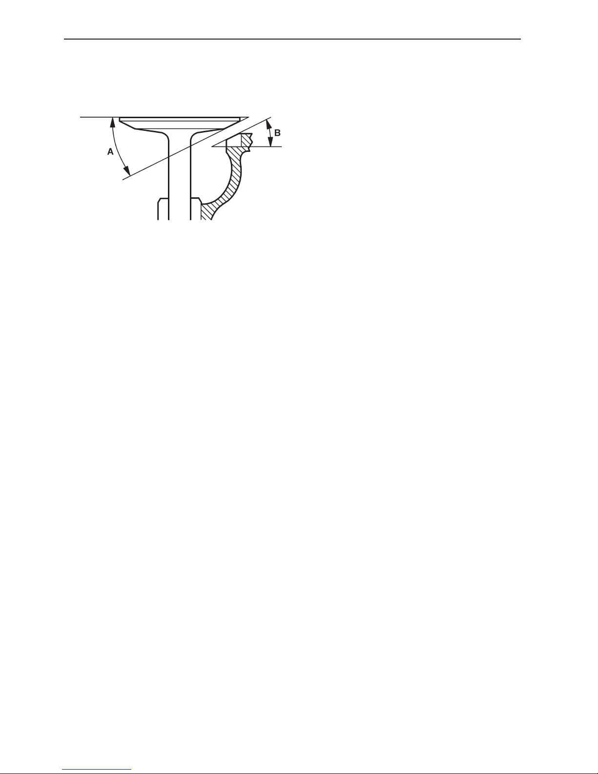
Valve seat angle (A):
Inlet .................................................................... 29.5°
Exhaust .............................................................. 29.5°
Seat angle in cylinder head (B):
Inlet .................................................................... 30°
Exhaust .............................................................. 30°
Dimension between valve head and cylinder head plane:
Inlet .................................................................... min 0.95 mm (0.037401")
Exhaust .............................................................. min 1.25 mm (0.049212")
NOTE! When the valve seats are changed, the valves must be changed at the same time.
Valve clearance, cold engine, setting value:
Inlet .................................................................... 0.2 mm (0.007874")
Exhaust
TAD940-941GE, TAD940-943VE ...................... 0.5 mm (0.019685")
TAD950-952VE ................................................. 0,8 mm (0.031496")
Valve clearance, cold engine, check value:
Inlet .................................................................... 0.15 -0.25 mm (0.005905 - 0.009842")
Exhaust
TAD940-941GE, TAD940-943VE ...................... 0.45 -0.55 mm (0.017716 - 0.021653")
TAD950-952VE ................................................. 0,75 - 0,85 mm (0.029527 - 0.033465")
TAD950-952VE
Clearance, double rocker arm
– base circle on camshaft ......................................using gauge tool

Technical data
11
Group 20
Valve seats
Outer diameter (A)
Standard:
Inlet ....................................................................
TAD940-941GE, TAD940-943VE ...................... 40.0 mm (1.5748")
TAD950-952VE ................................................. 42,0 mm (1.6535")
Exhaust
TAD940-941GE, TAD940-943VE ...................... 41.0 mm (1.61417")
TAD950-952VE ................................................. 40,0 mm (1.5748")
Oversize dimension:
Inlet
TAD940-941GE, TAD940-943VE ...................... 40.3 mm (1.586611")
TAD950-952VE ................................................. 42,3 mm (1.665349")
Exhaust
TAD940-941GE, TAD940-943VE ...................... 41.3 mm (1.625981")
TAD950-952VE ................................................. 40,3 mm (1.586609")
Height (B):
Inlet
TAD940-941GE, TAD940-943VE ...................... 7.3 mm (0.287401")
TAD950-952VE ................................................. 7,4 mm (0.291338")
Exhaust
TAD940-941GE, TAD940-943VE ...................... 7.4 mm (0.291338")
TAD950-952VE ................................................. 6,4 mm (0.251968")
 Loading...