

Volvo Penta TAD1242GE, TAD1240GE, TAD1241VE, TAD1241GE, TAD1242VE Technical Description
...Page 1
VOLVO PENTA GENSET ENGINE
TAD1242GE
1500 rpm, 387 kW (526 hp) – 1800 rpm, 430 kW (585 hp)
The TAD1242GE is a powerful, reliable
and economical Generating Set Diesel
Engine built on the dependable in-line six
design.
Durability & low noise
Designed for easiest, fastest and most
economical installation. Well-balanced to
produce smooth and vibration-free operation with low noise level.
To maintain a controlled working temperature in cylinders and combustion
chambers, the engine is equipped with
piston cooling. The engine is also fitted
with replaceable cylinder liners and valve
seats/guides to ensure maximum durability and service life of the engine.
Low exhaust emission
The state of the art, high-tech injection
and charging system with low internal
losses contributes to excellent combustion and low fuel consumption.
The TAD1242GE complies with EU
Stage 2 and TA-Luft -50% exhaust emission regulations.
Easy service & maintenance
Easily accessible service and maintenance points contribute to the ease of
service of the engine.
Technical description:
Engine and block
– Optimized cast iron cylinder block with opti-
mum distribution of forces without the block
being unnessarily heavy.
– Wet, replaceable cylinder liners
– Piston cooling for low piston temperature
and reduced ring temperature
– Tapered connecting rods for reduce risk of
piston cracking
– Crankshaft induction hardened bearing
surfaces and fillets with seven bearings for
moderate load on main and high-end bear-
ings
– Case hardened and Nitrocarburized trans-
mission gears for heavy duty operation
– Keystone top compression rings for long
service life
– Viscous type crankshaft vibration dampers to
withstand single bearing alternator torsional
vibrations
– Replaceable valve guides and valve seats
– Over head camshaft and four valves per cyl-
inder
Lubrication system
– Full flow oil cooler
– Full flow disposable spin-on oil filter, for ex-
tra high filtration
– The lubricating oil level can be measured
during operation
– Gear type lubricating oil pump, gear driven
by the transmission
Fuel system
– Non-return fuel valve
– Electronic Unit Injectors
– Fuel prefilter with water separator and water-
in-fuel indicator / alarm
– Gear driven low-pressure fuel pump
– Fine fuel filter with manual feed pump and
fuel pressure switch
– Fuel shut-off valve, electrically operated
Cooling system
– Efficient cooling with accurate coolant con-
trol through a water distribution duct in the
cylinder block. Reliable sleeve thermostat
with minimum pressure drop
Features
– Maintained performance, air temp 40°C
– Cooling system (55°C)
– Fully electronic with Volvo Penta EDC III
– Dual frequency switch (between 1500 rpm and 1800 rpm)
– High power density
– Emission compliant
– Low noise levels
– Gen Pac configuration
– Gear driven, maintenance-free coolant pump
with high degree of efficiency
– Coolant filter as standard
Turbo charger
– Efficient and reliable turbo charger
– Extra oil filter for the turbo charger
Electrical system
– Electronical Diesel Control III (EDCIII), an
electronically controlled processing system
which optimizes engine performance. It also
includes advanced facilities for diagnostics
and fault tracing
– Three different ways for the customer to
connect his controls and instrument to the
engine. CAN SAE J1939 interface, CIU
(Control interface unit) and Stand alone
connections.
– Sensors for oil pressure, oil temp, boost
pressure, boost temp, coolant temp, fuel
temp, water in fuel, fuel pressure and two
speed sensors.
Page 2
TAD1242GE
Technical Data
General
Engine designation ........................................................................ TAD1242GE
No. of cylinders and configuration ........................................................in-line 6
Method of operation ................................................................................4-stroke
Bore, mm (in.) ...................................................................................... 131 (5.16)
Stroke, mm (in.) ...................................................................................150 (5.91)
Displacement, l (in3) ...................................................................12.13 (740.2)
Compression ratio ......................................................................................17.5:1
Dry weight, kg (lb) ......................................................................... 1380 (3036)
With Gen Pac, kg (lb) .................................................................. 1645 (3627)
Wet weight, kg (lb) .........................................................................1455 (3201)
With Gen Pac, kg (lb) .................................................................. 1720 (3792)
Performance
kW (hp) 1500 rpm 1800 rpm
Prime Power 352 (479) 391 (532)
Max Standby Power 387 (526) 430 (585)
Lubrication system
Oil consumption, liter/h (US gal/h) 1500 rpm 1800 rpm
Prime Power 0.12 (0.032) 0.14 (0.037)
Max Standby Power 0.14 (0.037) 0.15 (0.040)
Oil system capacity incl filters, liter ...............................................................35
Oil change intervals at specification
VDS-2, h ........................................................................................................... 600
VDS, ACEA E3, h ............................................................................................400
ACEA E1, E2, API CD, CF, CF-4, CG-4, h ...............................................200
Fuel system
Specific fuel consumption at
Prime Power, g/kWh (lb/hph) 1500 rpm 1800 rpm
25 % 216 (0.350) 231 (0.374)
50 % 199 (0.323) 208 (0.330)
75 % 195 (0.316) 200 (0.324)
100 % 198 (0.321) 202 (0.327)
Max Standby Power, g/kWh (lb/hph) 1500 rpm 1800 rpm
25 % 211 (0.347) 225 (0.365)
50 % 197 (0.319) 203 (0.329)
75 % 195 (0.316) 200 (0.324)
100 % 199 (0.323) 203 (0.329)
Intake and exhaust system
Air consumption at 27°C, m³/min (cfm) 1500 rpm 1800 rpm
Prime Power 23.5 (830) 28.0 (989)
Max Standby Power 25.0 (883) 29.0 (1024)
Max allowable air intake restriction, kPa (In wc) ............................... 5 (20.1)
Heat rejection to exhaust,
kW (BTU/min) 1500 rpm 1800 rpm
Prime Power 250 (14217) 272(15468)
Max Standby Power 276 (15696) 306 (17402)
Exhaust gas temperature after turbine,
°C (°F) 1500 rpm 1800 rpm
Prime Power 490 (914) 465 (869)
Max Standby Power 505 (941) 490 (914)
Max allowable back-pressure in exhaust line, kPa (In wc) ........... 10 (40.2)
Exhaust gas flow, m³/min (cfm) 1500 rpm 1800 rpm
Prime power 58 (2048) 66 (2331)
Max Standby Power 63 (2225) 72 (2543)
Cooling system
Heat rejection radiation from engine,
kW (BTU/min) 1500 rpm 1800 rpm
Prime Power 17 (967) 18 (1024)
Max Standby Power 18 (1024) 20 (1137)
Heat rejection to coolant kW (BTU/min)
Prime Power 123 (6995) 139 (7905)
Max Standby Power 125 (7109) 143 (8132)
Fan power consumption, kW (hp) 9 (12) 15 (20)
Note! Not all models, standard equipment and accessories are available in all countries.
All specifications are subject to change without notice.
The engine illustrated may not be entirely identical to production standard engines.
Power Standards
The engine performance corresponds to ISO 3046, BS
5514 and DIN 6271. The technical data applies to an engine
without cooling fan and operating on a fuel with calorific value
of 42.7 MJ /kg (18360 BTU/lb) and a density of 0.84 kg/liter
(7.01 lb/US gal), also where this involves a deviation from
the standards. Power output guaranteed within 0 to +2% att
rated ambient conditions at delivery. Ratings are based on
ISO 8528. Engine speed governing in accordance with ISO
3046/IV, class A1 and ISO 8528-5 class G3
Exhaust emissions
The engine complies with EU stage 2 emission legislation
according to the Non Road Directive EU 97/68/EEC. The
engine also complies with TA-luft -50% exhaust emission
regulations.
Rating Guidelines
PRIME POWER rating corresponds to ISO Standard Power for
continuous operation. It is applicable for supplying electrical power
at variable load for an unlimited number of hours instead of commercially purchased power. A10 % overload capability for govering
purpose is available for this rating.
MAXIMUM STANDBY POWER rating corresponds to ISO Standard Fuel Stop Power. It is applicable for supplying standby electrical power at variable load in areas with well established electrical
networks in the event of normal utility power failure. No overload
capability is available for this rating.
1 hp = 1 kW x 1.36
Information
For more technical data and information, please look in the Generating Set Engines Sales Guide.
Standard equipment Engine Gen Pac
Engine
Automatic belt tensioner
• •
Lift eyelets • •
Flywheel
Flywheel housing with conn. acc. to SAE 1
• •
Flywheel for 14” flex. plate and flexible coupling • •
Vibration dampers • •
Engine suspension
Fixed front suspension
• •
Lubrication system
Oil dipstick
• •
Full-flow oil filter of spin-on type • •
By-pass oil filter of spin-on type • •
Oil cooler, side mounted • •
Low noise oil sump • •
Fuel system
Fuel filters of disposable type
• •
Electronic unit injectors • •
Pre-filter with water separator • •
Intake and exhaust system
Air filter with replaceable paper insert
• •
Air restriction indicator • •
Air cooled exhaust manifold • •
Connecting flange for exhaust pipe • •
Exhaust flange with v-clamp • •
Turbo charger, low right side • •
Crankcase ventilation • •
Cooling system
Radiator incl intercooler
•¹) •
Gear driven coolant pump • •
Fan hub • •
Thrust fan •¹) •
Fan guard − •
Belt guard − •
Control system
Engine Management System (EMS) with
• •
CAN-bus interface SAE J1939 and stand alone
interface
Alternator
Alternator 60A / 24 V
• •
Starting system
Starter motor, 6.0kW, 24 V
• •
Connection facility for extra starter motor • •
Instruments and senders
Temp.- and oil pressure for automatic
• •
stop/alarm 103°C
Other equipment
Expandable base frame
− •
Engine Packing
Plastic warpping
1)
must be ordered, se order specification - optional equipment
− optional equipment or not applicable
• included in standard specification
• •
Dimensions TAD1242GE
Not for installation
A* = 1587 mm / 62.5 in
B* = 1120 mm / 44.1 in
C* = 1976 mm / 77.8 in
D = 2296 mm / 90.5 in (During transport)
D = Max 3311 mm / 130.5 in
*Incl. radiator and intercooler
http://www.brizmotors.ru/equipment/ctm/
v400/
English 02 -2009. © 2009 AB Volvo Penta
Page 3

Group 23 EDC III Design and operation
Design and operation
System description EDC III
EDC III, ”Electronic Diesel Control”, is an electronic system with CAN communication for diesel engine management. The system is developed by Volvo Penta and covers fuel management, diagnostic function, etc. The system consists of a control module, six unit injectors, a number of sensors that provide information to the control
module, and a data link connector for diagnostics and functionality checks. The EDC III system also has a ”stand
alone” interface that can be linked directly to the engine control module on the engine. The engine can be linked to
a ”CAN” interface and a ”Control Interface Unit” (CIU), which is an interface to the operator area.
Control module
The EDC III system processor is located in the control module, protected from moisture and vibrations.
The processor continually receives information regarding:
Engine speed
•
Charge air pressure
•
Charge air temperature
•
Coolant temperature
•
Oil pressure
•
Oil temperature
•
Fuel alarm, combined alarm for ”water in fuel” and
•
”fuel pressure”
Coolant level
•
This information is used to make exact determinations
on current operating conditions and allows the processor to calculate the correct amount of fuel, check the
condition of the engine, etc.
Fuel management
The engine’s fuel need is analyzed up to 100 times
per second (depending on engine speed). The quantity
and timing of fuel injection into the engine are controlled completely electronically via fuel valves on the
unit injectors.
This means that the engine always receives the correct amount of fuel under all operating conditions,
providing benefits including improved fuel economy
and minimized exhaust emissions.
The control module checks and controls the unit injectors so that the correct amount of fuel is injected into
each cylinder. It calculates and sets the injection angle. This control is done primarily with the help of the
tachometer sensors and the combined sensor for
charge air pressure/temperature.
The control module actuates the unit injectors via an
electronic signal to the unit injectors’ electromagnetically controlled fuel valve, which can then be opened
or closed.
When the fuel valve is open, fuel streams by, through
the unit injector holes and out through the fuel channel. Fuel is not injected into the cylinder at this stage.
When the fuel valve is closed, pressure is built up by
the mechanically driven pump piston of the unit injector. Once enough pressure is built up, fuel is injected
into the cylinder via the injector portion.
The fuel valve is reopened and pressure in the unit injector sinks while fuel injection to the cylinder ceases.
To determine when the fuel valve should be opened or
closed, the control module has access to signals from
sensors and switches.
12
Page 4

Group 23 EDC III Design and operation
Calculation of fuel quantity
The amount of fuel injected into a cylinder is calculated by the control module. The calculation gives the
amount of time the fuel valve is closed (as fuel is injected into the cylinder when the fuel valve is closed).
The parameters that determine the amount of fuel injected are:
Requested RPM
•
Engine protection functions
•
Temperature
•
Charge air pressure
•
Cylinder balance
When idling, the control module can provide the cylinders with different amounts of fuel. This makes the
engine idle more evenly. At higher RPM, all cylinders
receive an equal amount of fuel.
Diagnostic function
The EDC III system has an internal diagnostic function that makes it possible to detect faults in the engine and sensor.
The role of the diagnostic function is to detect and localize disruptions in the EDC III system, protect the
engine and ensure that the machine remains in working order during serious disturbances.
If a disturbance arises, the diagnostic indicator on the
indicator panel begins blinking. When the diagnosis
button is pressed, an error code is given as guidance
for any fault detection. The diagnostic function can be
read out via the display using the PC diagnostics program.
Idle adjustment (low idle)
Idle can be adjusted to a value between 600 and
1200 RPM.
13
Page 5
Group 23 EDC III Design and operation
Component description
The digits after the headings refer to ”Component diagram and location”.
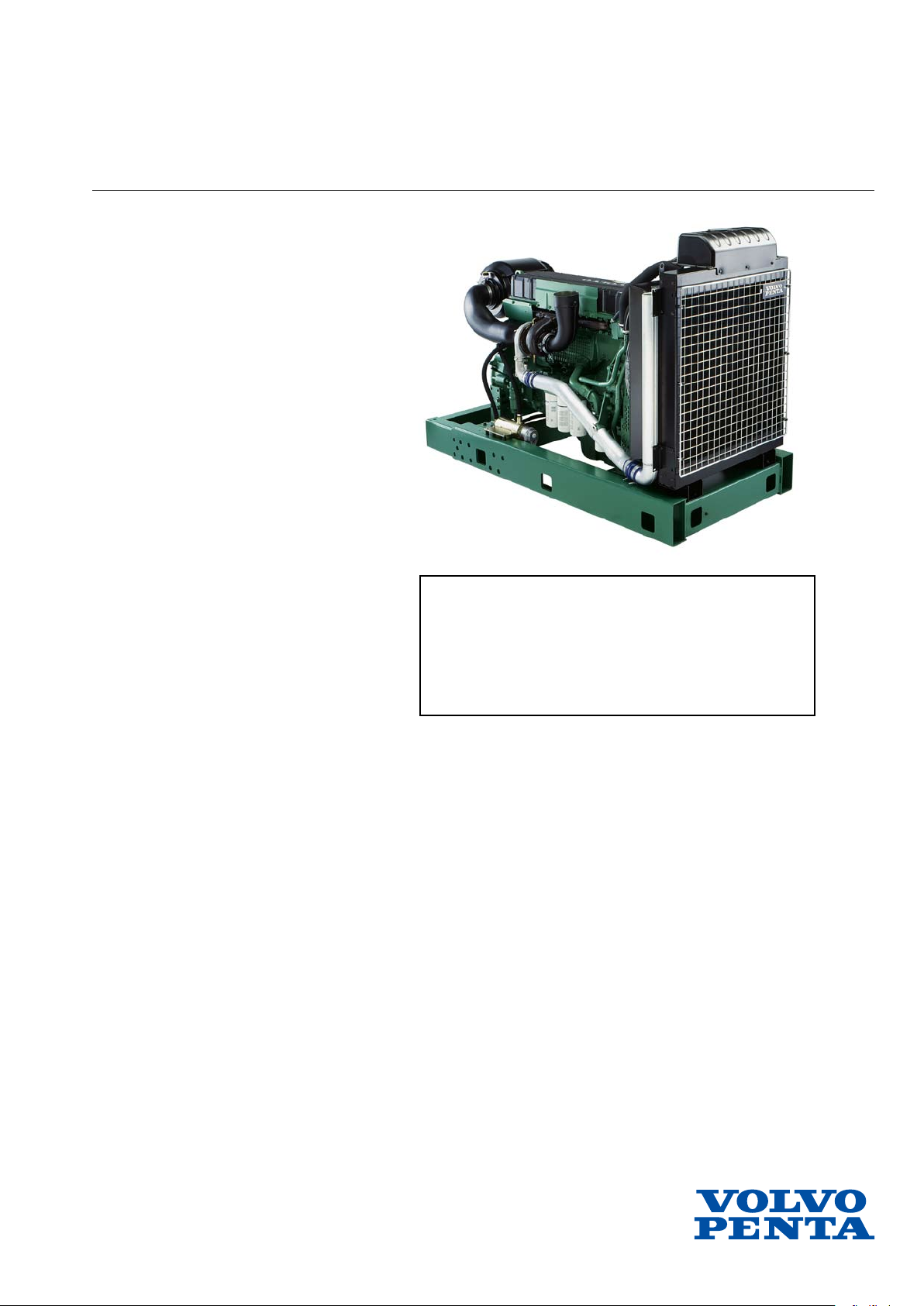
Water monitor, fuel pre-filter (19)
The monitor is located on the bottom of the fuel prefilter.
Its role is to guard against water in the fuel system.
The monitor consists of two copper pins between
which resistance is measured. When resistance falls
below the limit value, which indicates that there is water in the fuel, a warning signal is sent to the control
module.
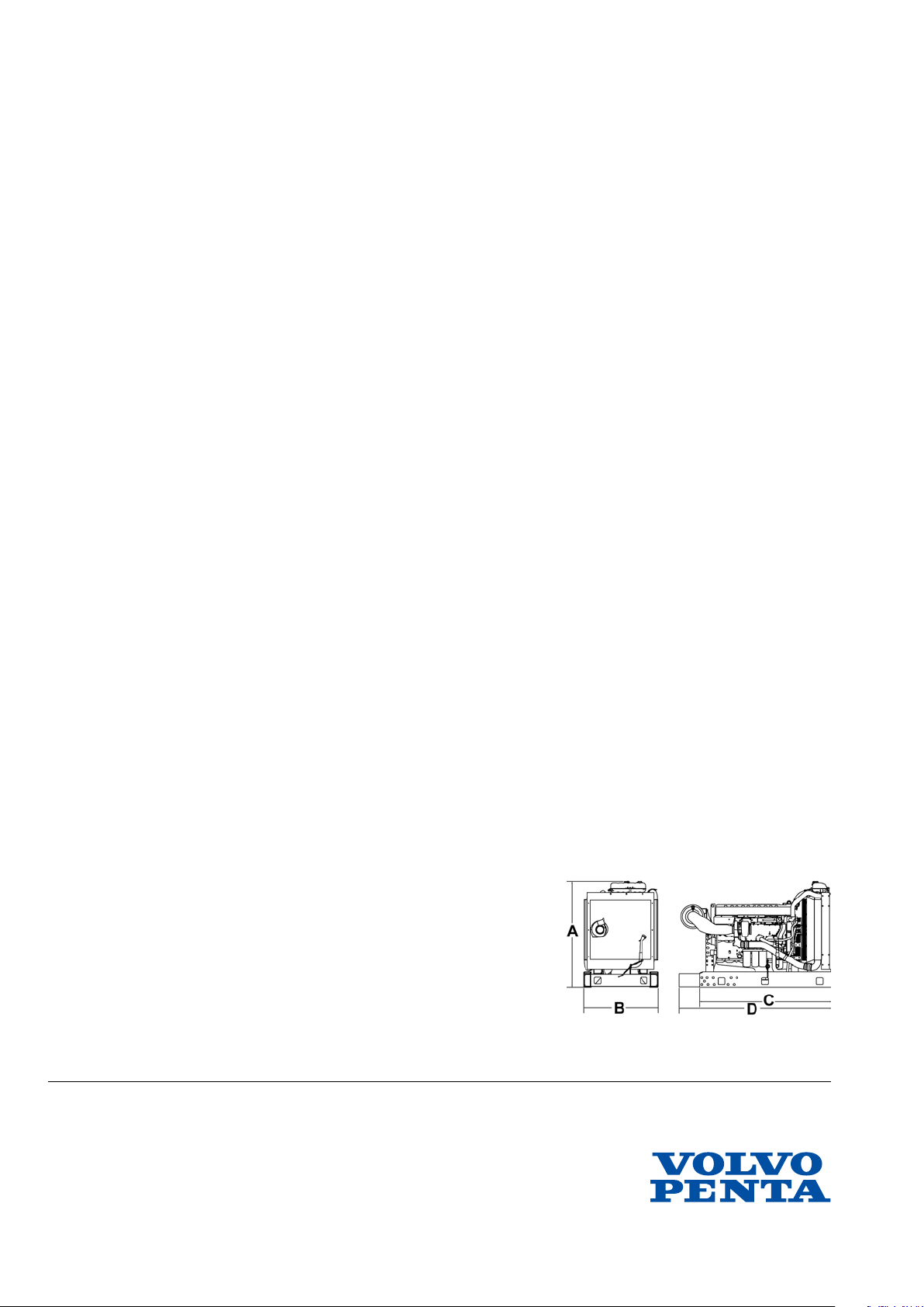
Tachometer sensor, camshaft (2)
The tachometer sensor is located on the upper timing
cover. The tachometer sensor, which is linked to the
camshaft, is an inductive sensor. It reads a toothed
wheel with seven pins. The impulses from the camshaft sensor provide the control module information on
which cylinder is next in line for injection and when it
receives it.
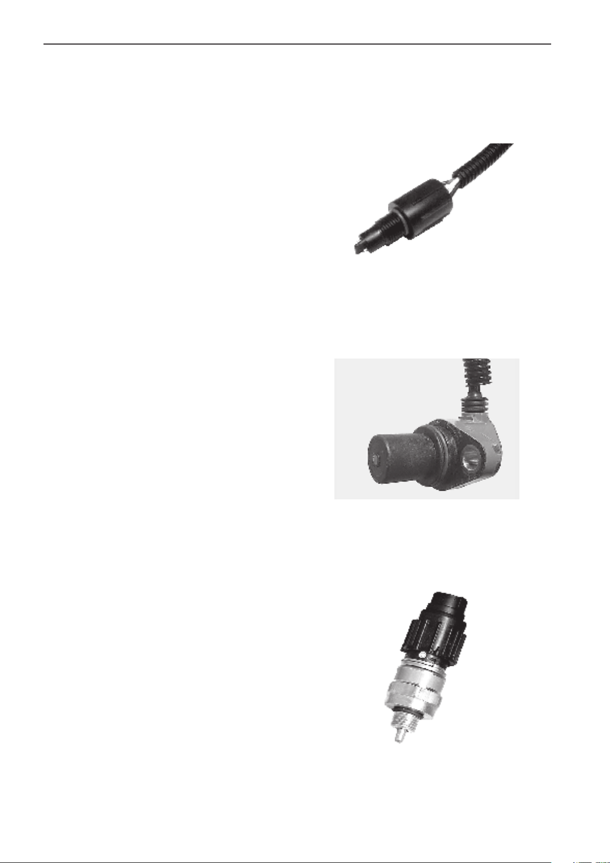
Oil pressure/temperature sensor
(10)
Oil pressure and oil temperature are measured by a
combined sensor that is located on the left-hand side
of the engine, next to the control module.
The sensor is mounted in the engine block so that
measurement is taken from the oil system’s main
channel. The sensor consists of a non-linear resistor
whose resistance is dependant on the temperature of
the resistor body. Resistance decreases as temperature increases. The pressure signal is a voltage signal
proportional to the pressure. The reference voltage for
the sensor is 5 Volts.
14
Page 6
Group 23 EDC III Design and operation
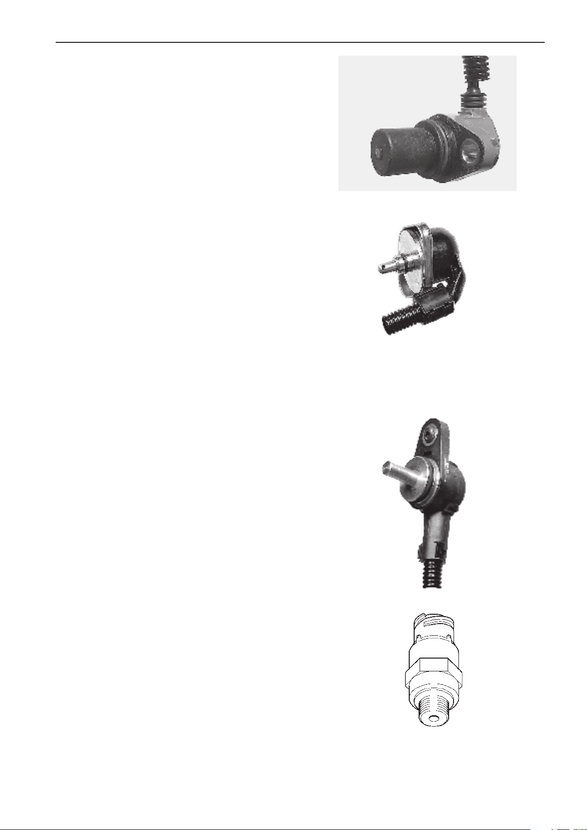
Tachometer sensor, flywheel (18)
This sensor is located on the left-hand side of the flywheel housing.
The tachometer sensor on the flywheel is an inductive
sensor. It reads the crankshaft position and engine
speed using grooves in the flywheel. The signal is
sent to the control module, which calculates the injection angle and amount of fuel.
Charge air pressure/temperature
sensor (6)
Charge air pressure and charge air temperature are
measured with a combined sensor located on the intake manifold.
The charge air pressure sensor measures absolute
pressure, which is the sum of the charge air pressure
and atmospheric pressure. The sensor sends a signal
to the control module in the form of voltage that is proportional to the absolute pressure. The sensor receives
a reference voltage of 5 Volts from the control module.
The charge air temperature sensor consists of a nonlinear resistor whose resistance depends on the temperature of the resistor body. Resistance decreases
as temperature increases.
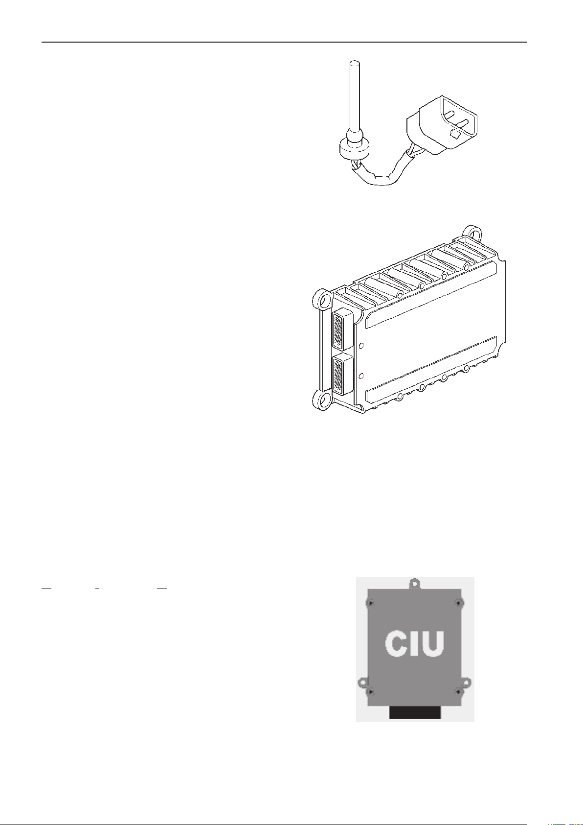
Coolant temperature sensor (15)
The sensor is located on the left-hand rear portion of
the cylinder head.
The sensor reads the temperature of the engine coolant and sends the information to the control module.
It consists of a non-linear resistor whose resistance
depends on the temperature of the resistor body. Resistance decreases as temperature increases.
Fuel pressure monitor (12)
The monitor is located on the left-hand side of the
engine, mounted in the fuel filter bracket.
Its task is to detect if the fuel pressure falls below
29 psi (2 BAR). The monitor is set to shut off when
pressure falls below 29 psi (2 BAR).
15
Page 7
Group 23 EDC III Design and operation
Coolant level monitor (1)
This monitor is located in the expansion tank.
Its task is to detect if the coolant level in the cooling
system (expansion tank) is too low. The monitor consists of a contact that can be actuated magnetically.
A hull located around the monitor actuates the contact
differently depending on the coolant level. An alarm
signal is sent if the coolant level is too low.
Electronic Control Unit (ECU) (11)
The control module (EMS) checks and controls the
unit injectors so that the correct amount of fuel is injected into each cylinder. It calculates and sets the injection angle. This control is done primarily with the
help of the tachometer sensors and the combined
sensor for charge air pressure/temperature.
The EDC III system processor is located in the control unit, protected from moisture and vibrations.
The processor continually receives information regarding:
engine speed
•
charge air pressure
•
charge air temperature
•
coolant temperature
•
oil pressure
•
oil temperature
•
fuel alarm, combined alarm for ”water in fuel” and
•
”fuel pressure”
coolant level
•
This information is used to make exact determinations
on current operating conditions and allows the processor to calculate the correct amount of fuel, check the
condition of the engine, etc.
Control Interface Unit (CIU)
The CIU is a control unit that handles all interaction
with the operator.
It communicates with the engine over two serial communication buses. J1939 is used for controlling and
monitoring the engine. J1587 is used for diagnostics
and backup.
The CIU loads a number of switches and speed requests and forwards them to the engine. It also controls four analogue instruments and up to nine warning
lamps. Using a diagnosis button and diagnostic lamp,
the operator can read out error codes from the system.
16
Page 8
Group 23 EDC III Design and operation
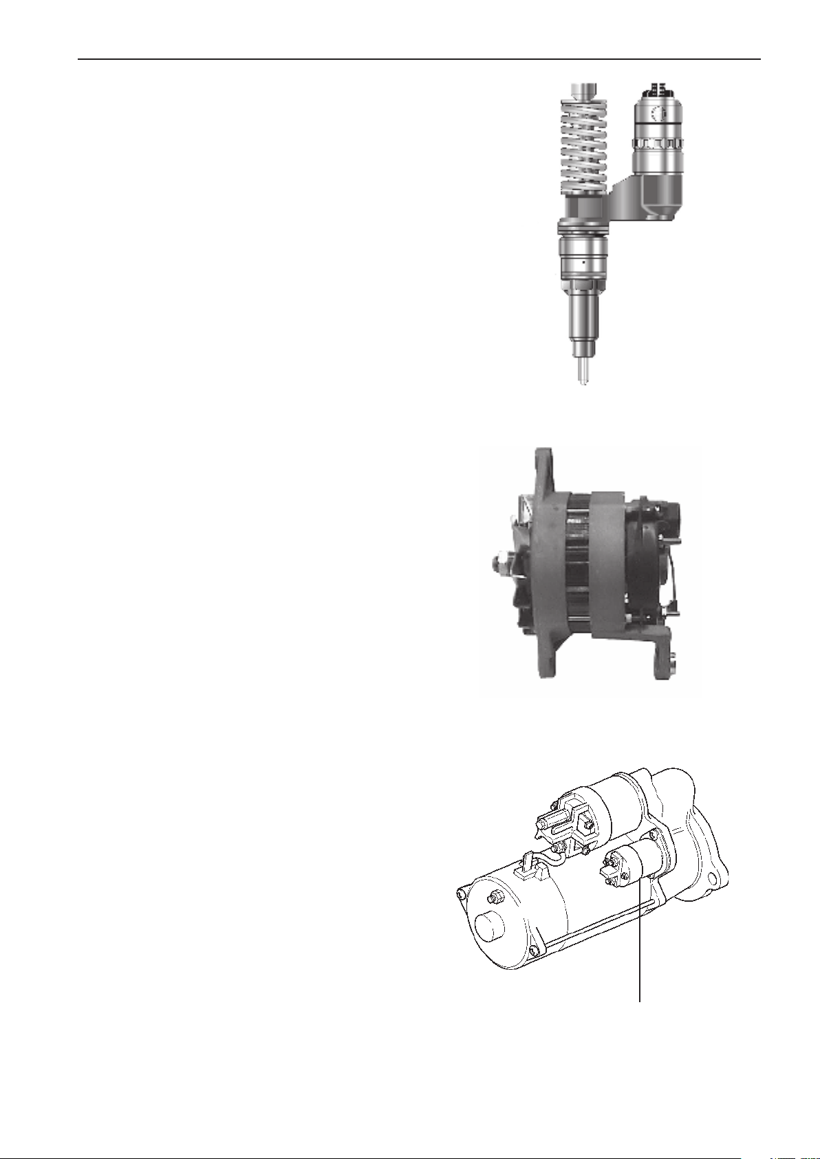
Unit injectors (20)
The unit injectors are located under the valve cover,
mounted in the cylinder head.
The engine’s fuel need is analyzed up to 100 times
per second (depending on engine speed). The quantity
and timing of fuel injection into the engine are controlled completely electronically via the unit injectors’
electromagnetically operated fuel valves. This means
that the engine always receives the correct amount of
fuel under all operating conditions, providing benefits
including improved fuel economy and minimized exhaust emissions.
Generator (8)
The belt-driven generator is located on the left-hand
front edge of the engine.
The voltage regulator of the generator is equipped with
a sensor system. The sensor system compares the
charging voltage between the generator connections,
B+ and B-, with the actual voltage between the positive and negative poles of the batteries. The voltage regulator then compensates for any voltage drop in the
lines between the generator and the battery by increasing the charging voltage from the generator as
needed.
Starter motor (16)
The starter motor is mounted on the flywheel housing
on the right-hand side of the engine.
When the motor is cut in, a gear on the armature shaft
of the starter motor is moved along the axis so that it
meshes with the gear ring of the engine’s flywheel.
The actuator solenoid of the starter motor controls
both the axial movement of the gear and connection
of the starter motor.
In turn, the actuator solenoid of the starter motor is
cut in via the start relay, which is activated when the
ignition key is turned to position III or the start button
is depressed.
The starter motor relay (1) is mounted next to the starter motor solenoid.
1
17
Page 9
Group 23 EDC III Design and operation
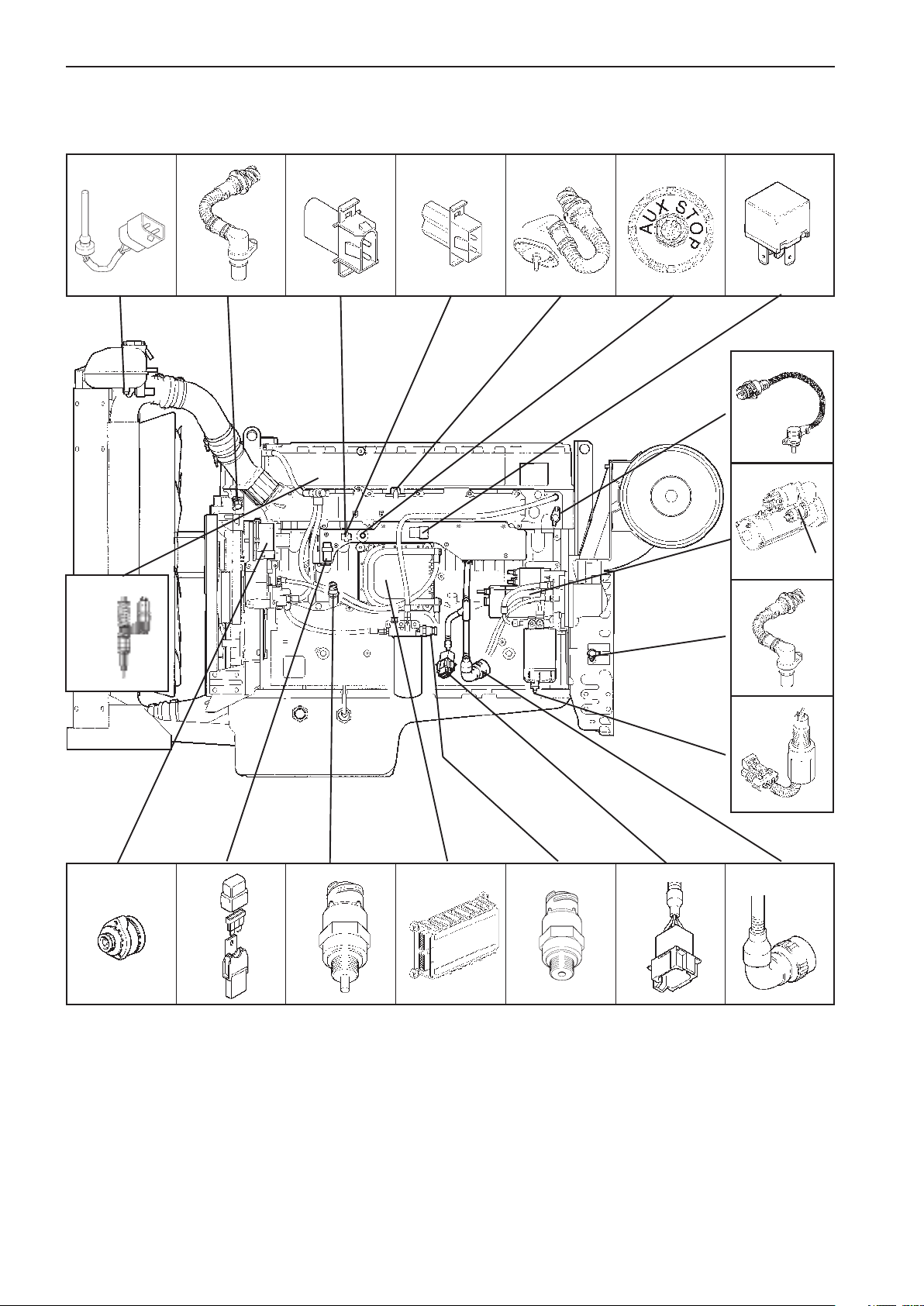
Component diagram and location
20
3
64512
7
15
16
17
18
911128
1. Coolant level monitor
2. Tachometer sensor, camshaft
3. Connection, diagnostic tool*
4. Programming plug*
5. Charge air pressure/temperature sensor
6. Extra stop
7. Main relay*
8. Generator
9. Fuse 10A
10. Oil pressure/temperature sensor
10
13
11. Control unit (ECU)
12. Fuel pressure monitor
13. 8–pin connection (Data bus)
14. 23–pin connection (Stand alone)
15. Coolant temperature sensor
16. Starter motor
17. Starter motor relay
18. Tachometer sensor, flywheel
19. Water monitor, fuel filter
20. Unit injectors (one per cylinder)
19
14
* Inside the Cover
18
Page 10

Group 23 EDC III Limit values
Limit values
Limit values, electronic control unit (ECU) TAD1240GE,
TAD1241-42GE/VE
Alarm values
The maximum permissible values for charge air and coolant temperatures, for example, can be adjusted with the
parameter setting tool and can thus vary within alarm limits.
If the alarm values are exceeded, the system reduces the amount of fuel until the value is once again within the
permissible interval.
This function is a customer parameter that can be completely disengaged.
Alarm limits TAD1240–42GE/VE:
Coolant temperature: Alarm lamp lights Engine is switched off Engine output 50%
Standard value Volvo Penta 98°C / 208°F 100°C / 212°F
Parameter setting (can be set
by the customer) 95–101°C / 203-214°F +2°C / 36°F over the alarm value
NOTE: Engine protection can be switched off.
Coolant level:
Alarm lamp lights when the contact is activated and
the engine is switched off
Alarm switch is activated
NOTE: Engine protection can be switched off.
Charge air temperature:
Standard value Volvo Penta 83°C / 181°F 85°C / 185°F
NOTE: Engine protection can be switched off.
Oil pressure:
Standard value Volvo Penta Idle: 0.7 bar (10,2 psi) For oil pressure 0.3 bar (4,4 psi)
lower than alarm value
>1500 RPM: 2.5 bar For oil pressure 0.3 bar (4,4 psi)
(36,3 psi) lower than alarm value
NOTE: Engine protection can be switched off.
Oil temperature:
Standard value Volvo Penta 125°C / 257°F 127°C / 261°F
Parameter setting (can be set
by customer) 120–130°C / 248-266°F +2°C / 36°F over alarm value
NOTE: Engine protection can be switched off.
Fuel pressure:
Standard value Volvo Penta <2 bar (<29 psi) Engine not switched off
Monitor, water in fuel: Alarm lamp lights
RPM:
Standard value Volvo Penta Max. operational RPM + 20%
Activates upon operational RPM +15%.
Parameter setting (can be set by customer)
Max. operational RPM + 10–20%
NOTE: Engine protection is switched off as standard.
19
Page 11
Group 23 EDC III Gränsvärden
Limit values, electronic control unit (ECU) TWD1240VE
Alarm limits:
Coolant temperature: Alarm lamp lights Engine is switched off Engine output 50%
Standard value Volvo Penta 98°C / 208°F 100°C / 212°F
Parameter setting (can be
set by the customer) 95–101°C / 203-214°F +2°C / 36°F over the alarm value
NOTE: Engine protection can be switched off.
Coolant level: Alarm lamp lights when the contact is activated
and the engine is switched off
NOTE: Engine protection can be switched off.
Charge air temperature:
Standard value Volvo Penta 100°C / 212 °F 102°C / 216°F
NOTE: Engine protection can be switched off.
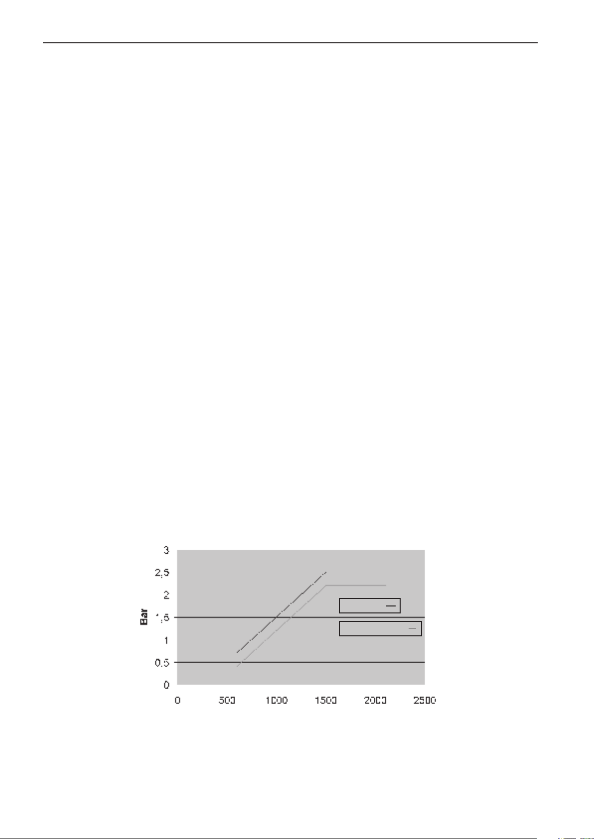
Oil pressure:
Standard value Volvo Penta Idle: 0.7 bar (10,2 psi) For oil pressure 0.3 bar (4,4 psi)
lower than alarm value
>1500 RPM: 2.5 bar For oil pressure 0.3 bar (4,4 psi)
(36,3 psi) lower than alarm value
* See diagram: ”Oil pressure” below.
NOTE: Engine protection can be switched off.
Oil temperature:
Standard value Volvo Penta 125°C / 257°F 127°C / 261°F
Parameter setting (can be
set by the customer) 120–130°C / 248-266°F +2°C / 36°F over
alarm value
NOTE: Engine protection can be switched off.
Fuel pressure:
Standard value Volvo Penta <2 bar (<29 psi) Engine not switched off
Monitor, water in fuel: Alarm lamp lights
*Oil pressure
Alarm limit
Engine is switched off
20
rpm
Page 12
Group 23 EDC III Limit values
Limp-home values (emergency control
values)
The control unit uses these bases value to be able to
run the engine if a technical error arises in the system
or its peripheral equipment, sensors, etc.
The following values (Limp-home values) are stored
in the control unit:
Charge air temperature +45°C / 113°F
Coolant temperature -15°C / 5°F
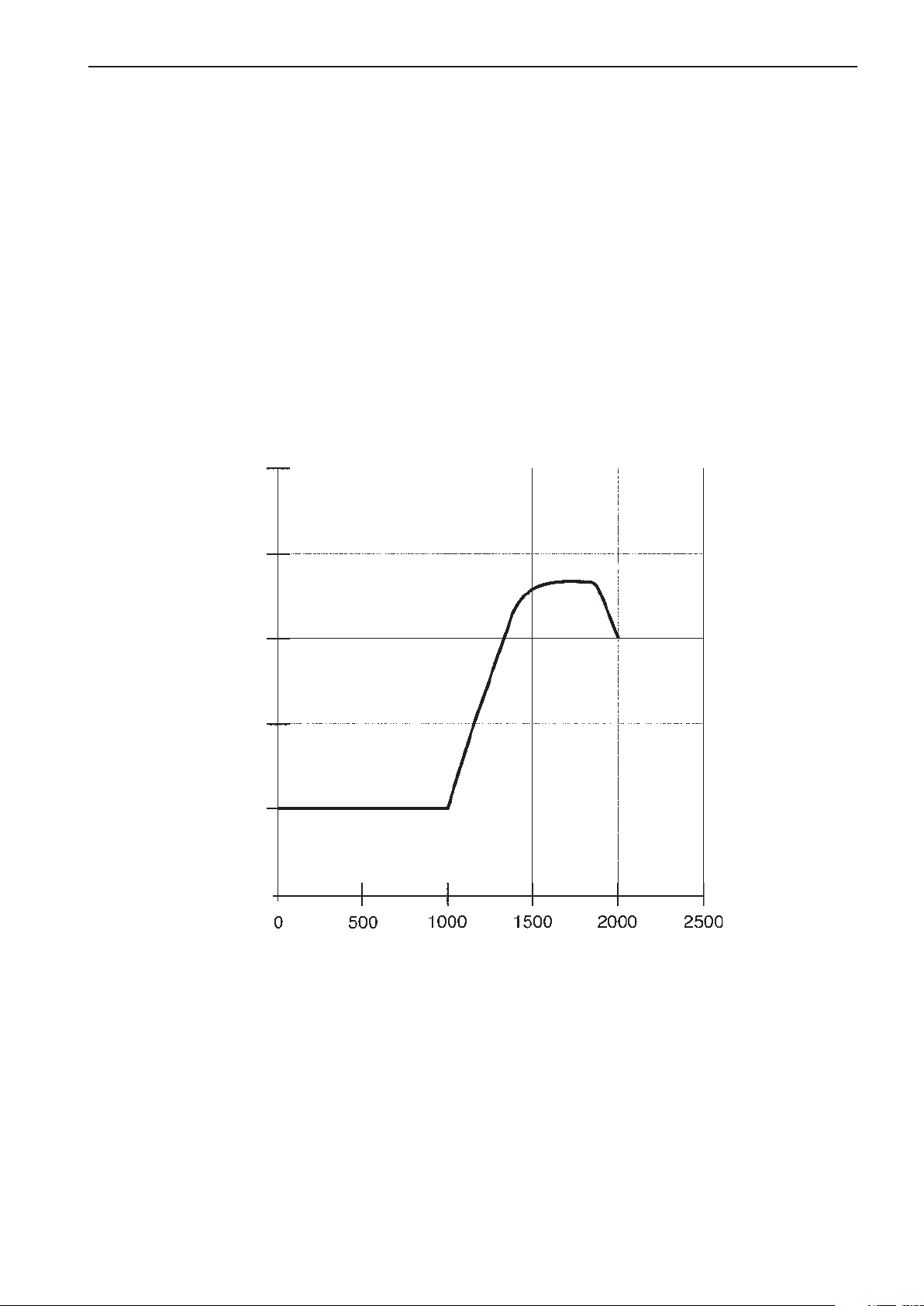
Charge air pressure See diagram below
Engine speed:
TAD1240–42GE/VE RPM frozen
TWD1240VE Idle
3.0
Charge air
pressure
2.5
2.0
bar
1.5
1.0
0
rpm
21
Page 13

Group 23 EDC III Repair instructions
Repair instructions
When working with EDC III
Follow the instructions below so as not to damage the control unit of the EDC system:
Never cut off the main current when the engine is running.
•
Never disconnect battery cables when the engine is running.
•
When quick charging the batteries, the main switch must be turned off or the battery cables must be discon-
•
nected.
During normal maintenance charging, the main switch does not need to be turned off.
Only batteries should be used for jumping. Jumping devices may cause a surge and damage the
•
control unit.
Cut off power to the EDC III system before disconnecting the 2 x 36-pin cable glove from the control unit.
•
If damage to the wiring harness is detected, the cable glove should be disconnected from the control unit.
•
IMPORTANT! The cable glove should be disconnected from the control unit when welding.
When removing a connector from a sensor, be careful not to expose the contact pin to oil or any
•
other fluid.
This could cause a contact problem or, if oil runs down to the pressure sensing membrane, the sensor could
show an incorrect value.
22
Page 14
Group 23 EDC III Repair instructions
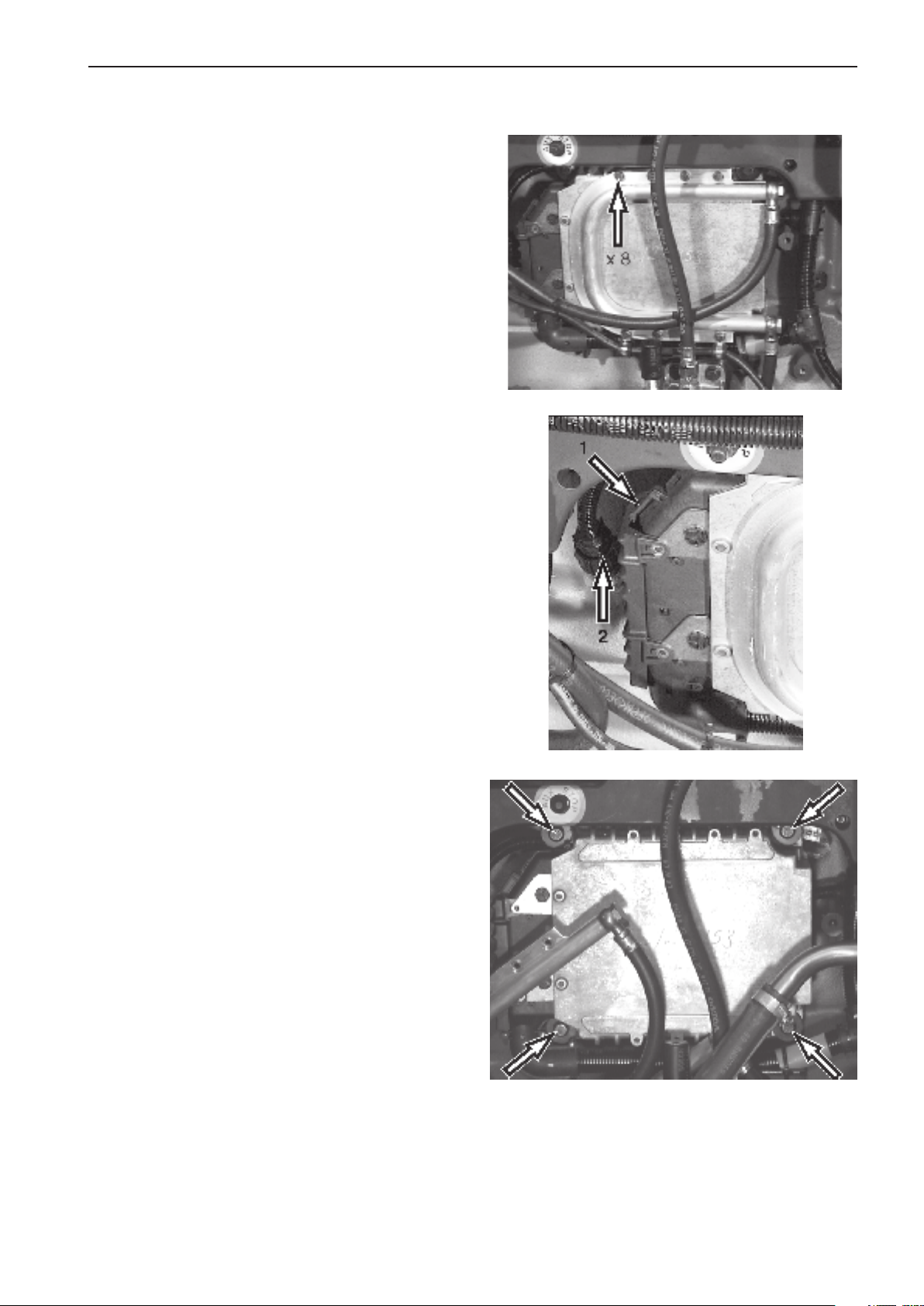
Electronic Control unit (ECU),
replacement
1. Cut off power to the engine.
2. Remove the fuel cooling coil and fuel line clamps
from the control unit.
Bend aside the cooling coil.
3. Disconnect the cable glove from the control unit.
Press in the catch (1) and push the cable glove (2)
upwards.
4. Remove the control unit.
5. Transfer the rubber cushions to the new control
unit.
6. Fit the new control unit.
7. Connect the cable glove to the control unit.
When connecting the cable glove (2) to the
control unit, make sure that the safety catch (1) is
set.
8. Fit the cooling coil and fuel line clamps to the
control unit.
NOTE: The retaining bolts of the fuel cooling coil are
self-tapping as there are no threads in the control unit.
9. Start the engine and perform leakage and
functionality checks.
23
Page 15
Group 23 EDC III Repair instructions
Start with booster batteries
WARNING! Be sure to have good ventilation.
The batteries build oxyhydrogen gas, which is
very flammable and explosive. A short-circuit,
open flame or spark could cause an explosion.
WARNING! Never confuse the position of the
cables on the battery. Confusing battery poles
when jumpstarting with battery cables causes
short-circuits and sparks, which can cause explosion and greatly damage electrical engine
components.
1. Check that the voltage of the booster battery is
the same as the engine’s system voltage.
2. First connect the red (+) jumper cable to the
positive pole (+) of the discharged batteries and
then to the positive pole (+) of the booster
battery.
3. Then connect the black (-) jumper cable to the
negative pole (-) of the booster battery and a
spot a bit away from the negative pole (-) of the
discharged batteries, such as by the negative
lead’s connection to the starter motor.
WARNING! The black (-) jumper cable must absolutely not come in contact with the positive
lead’s connection to the starter motor.
4. Start the engine and run at high idle about
10 minutes to charge the batteries.
WARNING! Approaching or working on a running
engine is a safety risk.
Beware of rotating parts and hot surfaces.
Do not touch the connections during the start attempt.
Risk of sparks.
Do not lean over any of the batteries.
5. Switch off the engine.
Remove the jumper cables in reverse order from
fitting. One cable at a time!
24
Page 16

Group 23 EDC III Functionality check
Functionality check
PC diagnostics program
This program can read error codes that are stored in the engine control unit, check input and
•
output signals, read current values from engine sensors and then store and print test results.
The program enables service and workshop personnel to quickly localize and remedy errors in the
•
EDC III system.
A data link connector is used to connect to the engine control unit.
•
User information is included in the program.
•
Contact your Volvo Penta dealer to order software.
•
The role of the diagnostic function is to detect and localize disturbances in the EDC III system, protect the
•
engine and ensure that the machine remains in working order during serious disturbances.
If a disturbance arises, the diagnostic indicator on the indicator panel begins blinking.
•
When the diagnosis button is pressed, an error code is given as guidance for any fault detection.
25
Page 17

Group 23 EDC III Fault detection
Fault detection
A number of symptoms and possible causes for engine problems are described in the table below. Always contact
your Volvo Penta dealer if problems occur that you are not able to solve on your own.
WARNING! Read through the safety instructions for maintenance and service work in the chapter ”Safety information” before starting to work.
Symptoms and possible causes
Diagnosis button’s indicator is blinking See the chapter ”Diagnostic function”
The engine cannot be stopped 2, 5
The starter motor does not rotate 1, 2, 3, 4, 5, 6, 7, 8, 25
The starter motor rotates slowly 1, 2
The starter motor rotates normally, but the engine does not start 9, 10, 11, 12, 13
The engine starts, but stops again 9, 10, 11, 12, 14
The engine does not reach the correct operating speed at full throttle 10, 11, 12, 13, 14, 22, 26, 27, 28, 29
The engine runs unevenly 11, 12,13
High fuel consumption 13, 14, 16, 26
Black exhaust smoke 13, 14
Blue or white exhaust smoke 15, 16, 23
Low oil pressure 17
High coolant temperature 18, 19, 20, 21
Low coolant temperature 21
No or poor charging 2, 24
1. Discharged batteries
2. Poor contact/interruption on
electrical line
3. Main switch turned off
4. Fuse on wiring box blown
5. Faulty starter switch
6. Faulty main relay
7. Faulty starter motor relay
8. Faulty starter motor/solenoid
9. Fuel shortage:
– fuel cocks closed
– fuel tank empty/wrong tank
connected
10. Clogged fuel fine filter/pre-filter
(due to contaminates or
paraffin deposits in the fuel at
low temperature)
11. Air in fuel system
12. Water/contaminates in the fuel
13. Faulty unit injectors
14. Insufficient air supply to
engine:
– clogged air filter
– air leak between turbo-
charger and engine’s intake
manifold
– fouled compressor
in turbocharger
– faulty turbocharger
– poor engine compartment
ventilation
15. High coolant temperature
16. Low coolant temperature
17. Low oil level
18. Low coolant level
20. Faulty circulation pump
21. Defective thermostat
22. Clogged intercooler
23. High oil level
24. Generator drive belt is slipping
25. Water in engine
26. Great counterpressure in
27. Interruption, cable ”Pot+” to
28. High oil temperature
29. High charge-air temperature
exhaust system
pedal
26
19. Air in coolant system
Page 18
Group 23 EDC III Diagnostic function
Diagnostic function
Diagnostic function
The diagnostic function checks that the EDC III system is functioning normally.
The diagnostic function performs the following
tasks:
Detects and localizes disturbances
•
Notifies when disturbances are detected
•
Provides guidance for fault detection
•
Protects the engine and ensures that the machine
•
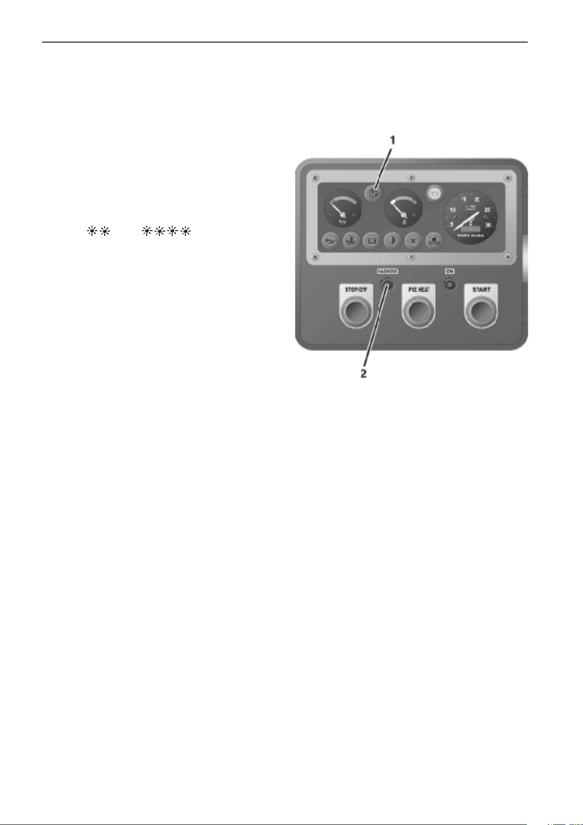
remains in working order when serious disturbances
are detected.
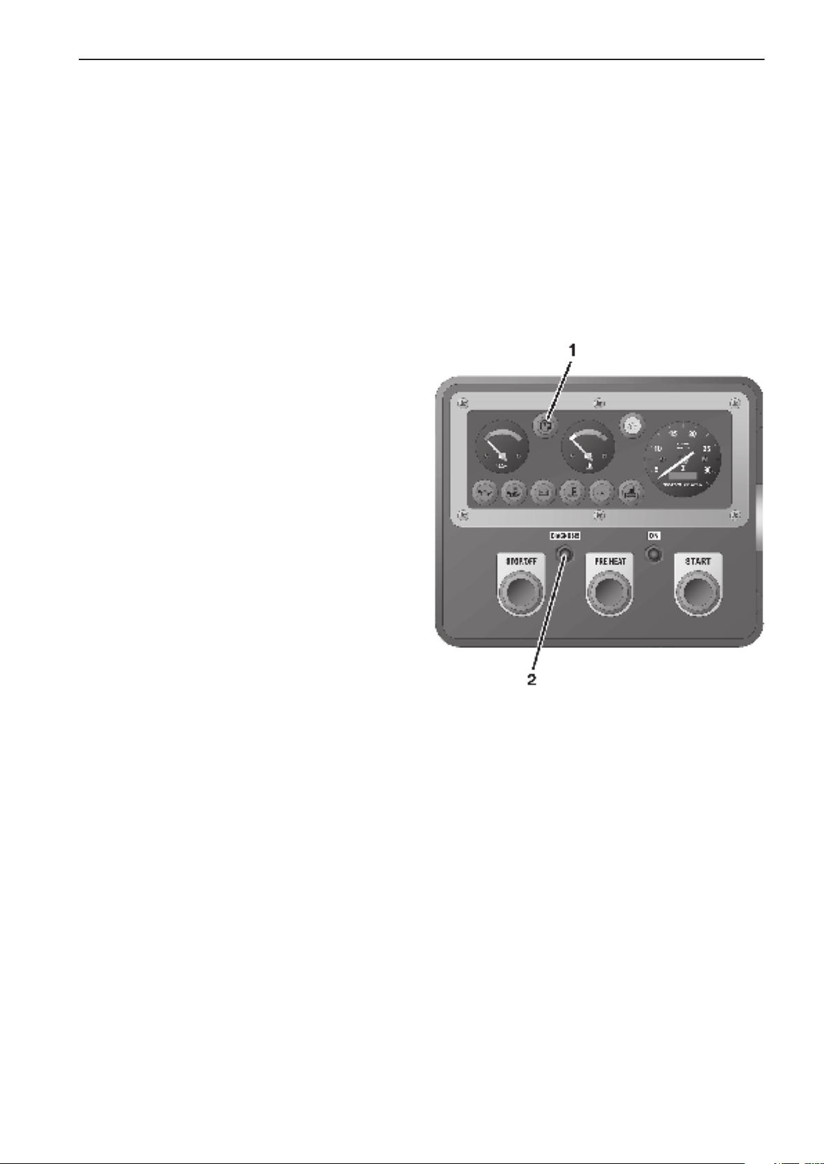
Notification of disturbance If the diagnostic function
detects a disturbance in the EDC III system, the operator is notified by the diagnostic lamp (1), which begins
to blink.
Guidance for fault detection If the diagnosis button
(2) is depressed and then released the diagnostic lamp
(1) blinks out an error code. The code is found in the
error code list, with information on cause, response and
corrective action.
The diagnostic function affects the engine in the
following manner when:
1 The diagnostic function has detected a minor
disturbance that will not damage the engine:
Response: The engine is not affected.
2. The diagnostic function has detected a serious
disturbance that will not immediately damage the
engine:
Response: TAD1240–42GE/VE: Engine is
switched off.
TWD1240VE: Engine is switched off or engine
torque is lowered until the value is normalized.
3. The diagnostic function has detected a serious
disturbance that makes it impossible to control
engine operation:
Response: TAD1240–42GE/VE: RPM maintained.
TWD1240VE: The engine goes to idle. Idle or
freezing of RPM can be set using the Volvo Penta
Parameter Tool.
If the diagnosis button’s
indicator blinks
1. Reduce RPM to idle.
2. Press the diagnosis button (2) to acknowledge the
message.
3. Release the diagnosis button and note the error
code that blinks out. (1) See ”Reading out error
codes”.
4. Look up the error code in the error code list and
follow the recommended course of action.
27
Page 19
Group 23 EDC III Diagnostic function
NOTE: If the warning lamps and other instruments
show normal function and the control is working normally, the operator can choose to continue operating
and remedy the disturbance later. If the engine is switched off, certain error codes could disappear.
Reading out error codes
If the diagnosis button 2 is depressed and then released, an error code blinks out (1).
The error code consists of two groups of blinks separated by a two-second pause. The error code is read
by counting the number of blinks in each group.
Example: pause = Error code 2.4
The error code is stored and can be read as long as
the disturbance remains. The error code list contains
information on cause, response and corrective action.
Read out as follows:
1. Press in the diagnosis button (2)
2. Release the diagnosis button and note the error
code that blinks out (1).
3. Repeat points 1–2. A new error code blinks out if
more codes are stored. Repeat until the first error
code reappears.
NOTE: When the first error code reappears all error
codes have been read out.
Erasing error codes
The error code memory of the diagnostic function is
reset when power to the engine is cut off.
NOTE: The power must be completely disconnected.
When the power is turned on, the diagnostic function
checks to see if there are any disturbances in the
EDC III system. If disturbances are present, new error
codes are set.
This means that:
1. Error codes for disturbances that have been
corrected or that have disappeared are erased
automatically.
2. Error codes for disturbances that have not been
corrected must be acknowledged and read out
every time the power is turned on.
If the diagnosis button is pushed after the error has
been corrected and saved error codes are erased the
code 1.1 (”No errors”) will blink out.
28
Page 20

Group 23 EDC III Diagnostic function
Error codes EDC III
WARNING! Read the safety instructions for maintenance and service work in the chapter ”Safety informa-
tion” before starting to work.
NOTE: The readout of the error codes below, such as 175 Code 2.1, means that 175 is read using the diagnostic tool.
2.1 is the blink code that is shown on the instrument box’s diagnostic lamp. See ”Reading out error codes”.
175 Code 2.1
Cause: Water in the fuel or low fuel pressure.
Response: Alarm lamp lights.
Corrective action:
Check the fuel dehumidification filter (drain the
•
fuel tank).
Check if it is possible to increase the pressure
•
using the hand pump.
Check the fuel filter.
•
Check the fuel pre-filter
•
191 Code 2.2
Cause: Low coolant level.
Response: Engine is switched off (if this protective
feature has not been disabled by the parameter setting tool).
Alarm lamp lights.
Corrective action:
Check the coolant level.
•
Check the function of the coolant level monitor.
•
15 Code 2.4
Cause: Tachometer sensor, flywheel. No signal.
Response: The engine is extremely hard to start and
runs unevenly if it does.
Corrective action:
Check that the sensor connector is fitted correctly.
•
Check that the wiring to the tachometer sensor is
•
not damaged.
Check that the tachometer sensor is correctly fit-
•
ted in the flywheel housing.
Check the function of the tachometer sensor.
•
Check the contact pressure in sleeves 30 and 31
•
in the black cable glove of the engine control unit
(ECU).
18 Code 2.4
Cause: RPM sensor, flywheel. Abnormal frequency.
Response: The engine is extremely hard to start and
runs unevenly if it does.
Corrective action:
Check that the tachometer sensor connector is fit-
•
ted correctly.
Check that the wiring to the tachometer sensor is
•
not damaged.
Check that the tachometer sensor is correctly fit-
•
ted in the flywheel housing.
Check the function of the tachometer sensor.
•
101 Code 2.4
Cause: Tachometer sensor, flywheel. Intermittent signal.
Response: The engine is extremely hard to start and
runs unevenly if it does.
Corrective action:
Check that the tachometer sensor connector is fit-
•
ted correctly.
Check that the wiring to the tachometer sensor is
•
not damaged.
Check that the tachometer sensor is correctly fit-
•
ted in the flywheel housing.
Check the function of the tachometer sensor.
•
Check the contact pressure in sleeves 30 and 31
•
in the black cable glove of the engine control unit
(ECU).
29
Page 21

Group 23 EDC III Diagnostic function
102 Code 2.5
Cause: RPM sensor, camshaft. No signal.
Response: The engine takes longer than normal to
start. The engine runs normally once underway.
Corrective action:
Check that the tachometer sensor connector is fit-
•
ted correctly.
Check that the wiring to the tachometer sensor is
•
not damaged.
Check that the tachometer sensor is correctly fit-
•
ted in the upper timing cover.
Check the function of the tachometer sensor.
•
Check the contact pressure in sleeves 7 and 18
•
in the black cable glove of the engine control unit
(ECU).
103 Code 2.5
Cause: RPM sensor, camshaft. Abnormal frequency.
Response: The engine takes longer than normal to
start. The engine runs normally once underway.
Corrective action:
Check that the tachometer sensor connector is fit-
•
ted correctly.
Check that the wiring to the tachometer sensor is
•
not damaged.
Check that the tachometer sensor is correctly fit-
•
ted in the upper timing cover.
Check the function of the tachometer sensor.
•
23 Code 2.7
Cause: RPM potentiometer connected to engine con-
trol unit (ECU).
Interrupted or shorted to positive (+).
Response: The engine goes to idle. If the pedal is released and then depressed again, the engine can
”limp home” using the idle contact.
Corrective action:
Check the the control’s connector is fitted correctly.
•
Check that the wiring to the sensor is not damaged.
•
Check the function of the sensor.
•
Check that the 23-pin connector is fitted correctly.
•
Check pin C and sleeve C in the 23-pin connector.
•
Check the contact pressure in sleeve 3 in the red
•
cable glove of the engine control unit (ECU).
24 Code 2.7
Cause: RPM potentiometer connected to the engine
control unit (ECU). Short to negative (-).
Response: The engine goes to idle. If the pedal is released and then depressed again, the engine can
”limp home” using the idle contact.
Corrective action:
Check that the potentiometer is connected cor-
•
rectly.
Check that the wiring to the potentiometer is not
•
damaged.
Check the function of the potentiometer.
•
21 Code 2.8
Cause: RPM potentiometer connected to CIU.
Short to negative (-).
Response: The engine goes to idle. If the pedal is released and then depressed again, the engine can
”limp home” using the idle contact.
Corrective action:
Check that the potentiometer is connected cor-
•
rectly.
Check that the wiring to the potentiometer is not
•
damaged.
Check the function of the potentiometer.
•
22 Code 2.8
Cause: RPM potentiometer connected to CIU.
Interrupted or shorted to positive (+).
Response: The engine goes to idle. If the pedal is released and then depressed again, the engine can
”limp home” using the idle contact.
Corrective action:
Check that the potentiometer is connected cor-
•
rectly.
Check that the wiring to the potentiometer is not
•
damaged.
Check the function of the potentiometer.
•
30
Page 22

Group 23 EDC III Diagnostic function
181 Code 3.1
Cause 1: Oil pressure sensor. Short to positive (+).
Response: None.
Corrective action:
Check that the wiring to the oil pressure sensor is
•
not damaged.
Check that the oil pressure sensor is connected
•
correctly.
182 Code 3.1
Cause: Oil pressure sensor. Interrupted or shorted to
negative (-).
Response: None.
Corrective action:
Check that the wiring to the oil pressure sensor is
•
not damaged.
Check that the oil pressure sensor is connected
•
correctly.
Check the contact pressure in sleeve 14 in the
•
black cable glove of the engine control unit
(ECU).
25 Code 3.2
Cause: Charge air temperature sensor. Interrupted or
shorted to positive (+).
Response: None.
Corrective action:
Check that the connector of the charge air tempe-
•
rature sensor is fitted correctly.
Check that the wiring to the charge air temperature
•
sensor is not damaged.
Check that the charge air temperature sensor is
•
fitted correctly.
Check the function of the charge air temperature
•
sensor.
Check the contact pressure in sleeve 2 in the
•
black cable glove of the engine control unit
(ECU).
26 Code 3.2
Cause: Charge air temperature sensor. Short to
negative (-).
Response: None.
Corrective action:
Check that the wiring to the charge air temperatu-
•
re sensor is not damaged.
Check that the charge air temperature sensor is
•
fitted correctly.
Check the function of the charge air temperature
•
sensor.
27 Code 3.3
Cause: Coolant temperature sensor. Interrupted or
shorted to positive (+).
Response: Preheating is activated even if the engine
is warm.
Corrective action:
Check that the connector of the coolant tempera-
•
ture sensor is fitted correctly.
Check that the wiring to the coolant temperature
•
sensor is not damaged.
Check that the coolant temperature sensor is fit-
•
ted correctly.
Check the function of the coolant temperature
•
sensor.
28 Code 3.3
Cause 1: Coolant temperature sensor. Short to negati-
ve (-).
Response: Preheating is activated even if the engine
is warm.
Corrective action:
Check that the wiring to the coolant temperature
•
sensor is not damaged.
Check that the coolant temperature sensor is fit-
•
ted correctly.
Check the function of the coolant temperature
•
sensor.
31
Page 23

Group 23 EDC III Diagnostic function
67 Code 3.4
Cause: Charge air pressure sensor. Short to positive (+).
Response: The engine smokes more than it usually
does when accelerating/under loading.
Corrective action:
Check that the wiring to the charge air pressure
•
sensor is not damaged.
Check the function of the charge air pressure sen-
•
sor.
68 Code 3.4
Cause 1: Charge air pressure sensor. Interrupted or
shorted to negative (-).
Response: The engine smokes more than it usually
does when accelerating/under loading.
Corrective action:
Check that the connector of the charge air pressu-
•
re sensor is fitted correctly.
Check that the wiring to the charge air pressure
•
sensor is not damaged.
Check that the charge air pressure sensor is fitted
•
correctly.
Check the function of the charge air pressure sen-
•
sor.
Check the contact pressure in sleeve 3 in the
•
black cable glove of the engine control unit
(ECU).
184 Code 3.7
185 Code 3.7
Cause: Oil temperature sensor. Short to negative (-).
Response: None.
Corrective action:
Check that the wiring to the oil temperature sen-
•
sor is not damaged.
Check that the oil temperature sensor is correctly
•
connected.
200 Code 4.1
Cause: Oil pressure alarm, circuit interrupted.
Response: Alarm lamp does not work. If the circuit is
interrupted during start-up, diagnostics are deactivated.
Corrective action:
Check the alarm lamp.
•
Check that the wiring to the alarm lamp is not da-
•
maged.
Check sleeve ”L” in the 23-pin connector.
•
Check the contact pressure in sleeve 35 in the
•
red cable glove of the engine control unit (ECU).
201 Code 4.1
Cause: Oil pressure alarm. Short to negative (-).
Response: Alarm lamp lights constantly
Corrective action:
Check that the wiring and connection to the alarm
•
lamp are not damaged.
Cause: Oil temperature sensor. Interrupted or shorted
to positive (+).
Response: None.
Corrective action:
Check that the wiring to the oil temperature sen-
•
sor is not damaged.
Check that the oil temperature sensor is correctly
•
connected.
Check the contact pressure in sleeve 1 in the
•
black cable glove of the engine control unit
(ECU).
202 Code 4.1
Cause: Oil pressure alarm. Short to positive (+).
Response: Alarm lamp does not work. If the circuit is
interrupted during start-up, diagnostics are deactivated.
Corrective action:
Check that the wiring and connection to the alarm
•
lamp are not damaged.
32
Page 24

Group 23 EDC III Diagnostic function
35 Code 4.2
Cause: Alarm for high coolant temp. Linked to Stand
Alone interface. Short to negative (-).
Response: Alarm lamp lights constantly.
Corrective action:
Check that the wiring to the alarm lamp is not
•
damaged.
Check that the alarm lamp is fitted correctly.
•
36 Code 4.2
Cause: Alarm for high coolant temp. Linked to Stand
Alone interface. Short to positive (+).
Response: Alarm lamp does not work. If the circuit is
interrupted during start-up, diagnostics are deactivated.
Corrective action:
Check that the wiring to the alarm lamp is not
•
damaged.
Check that the alarm lamp is fitted correctly.
•
221 Code 4.3
Cause: Lamp to indicate operation. Short to
negative (-).
Response: The indicator lamp shines constantly.
Corrective action:
Check that the wiring and connection to the alarm
•
lamp are not damaged.
222 Code 4.3
Cause: Lamp to indicate operation. Short to
positive (+).
Response: Indicator lamp does not work. If the circuit
is interrupted during start-up, diagnostics are deactivated.
Corrective action:
Check that the wiring and connection to the alarm
•
lamp are not damaged.
223 Code 4.4
226 Code 4.2
Cause: Alarm for high coolant temp. Circuit interrup-
tion.
Response: Alarm lamp does not work. If the circuit is
interrupted during start-up, diagnostics are deactivated.
Corrective action:
Check the alarm lamp for high coolant
•
temperature.
Check that the wiring to the alarm lamp is not
•
damaged.
Check sleeve ”N” in the 23-pin connector.
•
Check the contact pressure in sleeve 33 in the
•
black cable glove of the engine control unit
(ECU).
220 Code 4.3
Cause: Lamp to indicate operation. Interruption
Response: Indicator lamp does not work. If the circuit
is interrupted during start-up, diagnostics are deactivated.
Corrective action:
Check the alarm lamp.
•
Check that the wiring to the alarm lamp is not
•
damaged.
Check sleeve ”N” in the 23-pin connector.
•
Check the contact pressure in sleeve 33 in the
•
black connector of the engine control unit (ECU).
Cause: Overspeed alarm. Circuit interruption.
Response: Alarm lamp does not work. If the circuit is
interrupted during start-up, diagnostics are deactivated.
Corrective action:
Check the alarm lamp.
•
Check that the wiring to the alarm lamp is not da-
•
maged.
Check sleeve ”O” in the 23-pin connector.
•
Check the contact pressure in sleeve 36 in the
•
black cable glove of the engine control unit
(ECU).
224 Code 4.4
Cause: Overspeed alarm. Short to negative (-).
Response: Alarm lamp lights constantly.
Corrective action:
Check that the wiring and connection to the alarm
•
lamp are not damaged.
225 Code 4.4
Cause: Overspeed alarm. Short to positive (+).
Response: Alarm lamp does not work. If the circuit is
interrupted during start-up, diagnostics are deactivated.
Corrective action:
Check that the wiring and connection to the alarm
•
lamp are not damaged.
33
Page 25

Group 23 EDC III Diagnostic function
203 Code 4.5
Cause: Low coolant alarm. Circuit interruption.
Response: Alarm lamp does not work. If the circuit is
interrupted during start-up, diagnostics are deactivated.
Corrective action:
Check the alarm lamp.
•
Check that the wiring to the alarm lamp is not
•
damaged.
Check sleeve ”N” in the 23-pin connector.
•
Checkthe contact pressure in sleeve 33 in the
•
black cable glove of the engine control unit
(ECU).
204 Code 4.5
Cause: Low coolant alarm. Short to
negative (-).
Response: Alarm lamp lights constantly.
Corrective action:
Check that the wiring and connection to the alarm
•
lamp are not damaged.
205 Code 4.5
Cause: Low coolant alarm. Short to positive (+).
Response: Alarm lamp does not work. If the circuit is
interrupted during start-up, diagnostics are deactivated.
Corrective action:
Check that the wiring and connection to the alarm
•
lamp are not damaged.
41 Code 4.6
Cause: Start relay on starter motor.
Short to positive (+).
Response: Engine will not start.
Corrective action:
Check that the wiring to the relay is not damaged.
•
Check the function of the relay.
•
42 Code 4.6
Cause: Start relay on starter motor.
Short to negative (-).
Response: Engine will be started -> The starter motor
engages, but no start request is made when the ignition is switched on.
Engine running -> The starter motor engages, but no
start request is made.
Engine being started -> The starter motor does not disengage once the engine is started.
Corrective action:
Check that the wiring to the relay is not damaged.
•
Check the function of the relay.
•
107 Code 4.6
Cause: Starter motor relay. Circuit interruption.
Response: Engine will not start.
Corrective action:
Check that the cable to the starter motor (yellow/
•
black) is correctly connected.
Check that the cable to the starter motor (yellow/
•
black) is not damaged.
Check that the relay on the starter motor is whole.
•
Check the contact pressure in sleeve 31 in the
•
red cable glove of the engine control unit (ECU).
108 Code 4.7
Cause: Start input, engine control unit (ECU).
Short to negative (-).
Response: Engine will not start.
Corrective action:
Check that the wiring to the ignition key/start but-
•
ton is not damaged.
Check the contact pressure in sleeve ”E” in the
•
23-pin connector.
Check the contact pressure in sleeve 17 in the
•
connector on the engine.
34
Page 26

Group 23 EDC III Diagnostic function
109 Code 4.8
Cause: Stop input engine control unit (ECU).
Short to negative (-).
Response: The engine can only be stopped using
the emergency stop on the engine.
Corrective action:
Check that the wiring to the ignition key/start but-
•
ton is not damaged.
Check the contact pressure in sleeve ”H” in the
•
23-pin connector.
Checkthe contact pressure in sleeve 6 in the con-
•
nector on the engine.
43 Code 5.1
Cause: Main relay. Short to positive (+).
Response: The instrument panel loses power when
the key is twisted to start position. The engine will not
start.
Corrective action:
Check that the wiring to the relay is not damaged.
•
Check the function of the relay.
•
209 Code 5.3
Cause: Stop input on CIU. Short to negative (-).
Response: The engine can only be stopped using the
emergency stop on the engine.
Corrective action:
Check that the connections to the ignition key are
•
not damaged.
Check that the wiring to the ignition key is not
•
damaged.
211 Code 5.3
Cause: Stop input on CIU. Short to positive (+) or ac-
tivated too long.
Response: The engine stops. After 40 seconds an error code is shown. During this time, the engine cannot
be started. When the error code is blinked out on the
diagnostic lamp, the engine can be started but not
stopped.
Corrective action:
Check that the connections to the ignition key are
•
not damaged.
Check that the wiring to the ignition key is not
•
damaged.
208 Code 5.2
Cause: Start input on CIU. Short to negative (-).
Response: The engine cannot be started.
Corrective action:
Check that the connections to the ignition key are
•
not damaged.
Check that the wiring to the ignition key is not
•
damaged.
210 Code 5.2
Cause: Start input on CIU. Short to positive (+)
or activated too long.
Response: The engine starts immediately when the
ignition is turned on.
Corrective action:
Check that the connections to the ignition key are
•
not damaged.
Check that the wiring to the ignition key is not
•
damaged.
214 Code 5.3
Cause: Stop input on CIU. Interrupted or activated too
long.
Response: The engine stops. After 40 seconds an error code is shown. During this time, the engine cannot
be started. When the error code is blinked out on the
diagnostic lamp, the engine can be started but not
stopped.
Corrective action:
Check that the connections to the ignition key are
•
not damaged.
Check that the wiring to the ignition key is not
•
damaged.
35
Page 27

Group 23 EDC III Diagnostic function
74 Code 5.4
Cause: Preheating relay. Connection interruption
Response: Preheating cannot be activated.
Corrective action:
Check that the wiring to the input on the relay is
•
not damaged.
Check the function of the relay.
•
Check the contact pressure in sleeve 36 in the
•
red cable glove of the engine control unit (ECU).
75 Code 5.4
Cause: Preheating relay. Short to negative (-).
Response: Preheating is constantly activated.
Corrective action:
Check that the wiring to the input on the relay is
•
not damaged.
Check the function of the relay.
•
76 Code 5.4
Cause: Preheating relay. Short to positive (+).
Response: Preheating cannot be activated.
Corrective action:
Check that the wiring to the input on the relay is
•
not damaged.
Check the function of the relay.
•
183 Code 5.8
Cause Oil temperature is too high.
Response: Limited engine output (if this protective
feature has not been disabled by the parameter setting tool). Alarm lamp lights.
Corrective action:
Check the oil level.
•
Check the oil temperature.
•
Check the oil system thermostat.
•
Check the function of the oil temperature sensor.
•
31 Code 6.1
Cause: High coolant temperature.
Response: TAD1240–42GE: Limited engine output (if
this protective feature has not been disabled by the
parameter setting tool). Alarm lamp lights.
TWD1240VE: Engine is switched off (if this protective
feature has not been disabled by the parameter setting tool). Alarm indicator lights.
Corrective action:
Check the coolant level.
•
Check the intercooler (cleanness).
•
Check to see if there is air in the coolant system.
•
Check the pressure cap on the expansion tank.
•
Check the function of the coolant temperature
•
sensor.
Check the function of the thermostat.
•
60 Code 6.2
Cause Intake air temperature is too high.
Response: Engine output is limited to 50% (if this
protective feature has not been disabled by the parameter setting tool).
Corrective action:
Check the coolant level.
•
Check the intercooler (cleanness).
•
Check the function of the charge air temperature
•
sensor.
Check the function of the thermostat.
•
213 Code 6.4
Cause Datalink (CAN) error, CIU.
Response: Instruments and alarm lamps stop working.
Corrective action:
Check that the 8-pin connector is not damaged.
•
Check that the wiring between the CIU and the
•
engine control unit (ECU) is not damaged.
Check that sleeves 11 and 12 in the CIU connec-
•
tor are not damaged.
Check the contact pressure in sleeves 1 and 2 in
•
the red cable glove of the engine control unit
(ECU).
36
Page 28

Group 23 EDC III Diagnostic function
38 Code 6.5
Cause Datalink (CAN) error, engine control module
(EMS).
Response: Engine not running: the engine cannot be
started.
Engine running: engine goes to idle and can only be
stopped using the emergency stop.
Corrective action:
Check that the 8-pin connector is not damaged.
•
Check that the wiring between the CIU and the
•
engine control unit (ECU) is not damaged.
Check that sleeves 11 and 12 in the CIU connec-
•
tor are not damaged.
Check the contact pressure in sleeves 1 and 2 in
•
the red cable glove of the engine control unit
(ECU).
105 Code 6.5
Cause: Datalink error (CAN).
Response: Engine not running -> The engine cannot
be started. Engine running -> Engine goes to idle and
can only be stopped with the emergency stop.
Corrective action:
Check that the 8-pin connector is not damaged.
•
Check that the wiring between the CIU and the
•
engine control unit (ECU) is not damaged.
Check that sleeves 11 and 12 in the CIU connec-
•
tor are not damaged.
Check the contact pressure in sleeves 1 and 2 in
•
the red cable glove of the engine control module
(EMS).
106 Code 6.5
Cause: Datalink error (CAN).
Response: Engine not running -> The engine cannot
be started. Engine running -> Engine goes to idle and
can only be stopped with the emergency stop.
Corrective action:
Check that the 8-pin connector is not damaged.
•
Check that the 8-pin cable between the CIU and
•
the engine control unit (ECU) is not damaged.
Check that sleeves 11 and 12 in the CIU connec-
•
tor are not damaged.
Check the contact pressure in sleeves 1 and 2 in
•
the red cable glove of the engine control unit
(ECU).
180 Code 6.6
Cause: Oil pressure is too low.
Response: Engine is switched off (if this protective
feature has not been disabled by the parameter setting tool).
Alarm lamp lights.
Corrective action:
Check the oil level.
•
Check that the oil filter is not clogged.
•
Check the system pressure valves and the safety
•
valve in the oil system.
Check the function of the oil pressure sensor.
•
110 Code 7.1
Cause: Unit injector cylinder #1. Electronic error.
Response: The engine runs on 5 cylinders, sounds
uneven and has decreased performance.
Corrective action:
Check that the wiring to the unit injectors is not
•
damaged.
Check that the connections to the unit injector are
•
not damaged.
37
Page 29

Group 23 EDC III Diagnostic function
111 Code 7.1
Cause: Unit injector cylinder #1. Electronic error.
Response: The engine runs on 5 cylinders, sounds
uneven and has decreased performance.
Corrective action:
Check that the wiring to the unit injectors is not
•
damaged.
Check that the connections to the unit injector are
•
not damaged.
112 Code 7.1
Cause: Unit injector cylinder #1. Electronic error.
Response: The engine runs on 5 cylinders, sounds
uneven and has decreased performance.
Corrective action:
Check that the wiring to the unit injectors is not
•
damaged.
Check that the connections to the unit injector are
•
not damaged.
113 Code 7.1
Cause: Unit injector cylinder #1. Electronic error.
Response: The engine runs on 5 cylinders, sounds
uneven and has decreased performance.
Corrective action:
Check that the wiring to the unit injectors is not
•
damaged.
Check that the connections to the unit injector are
•
not damaged.
114 Code 7.1
Cause: Error in compression or the unit injector on cy-
linder #1.
Response: Cylinder balance is adversely affected ->
Uneven running at low RPM and low load.
Corrective action:
Check the fuel feed pressure.
•
Check the valve clearance.
•
Check that the unit injector and connection cable
•
are not damaged.
Do a compression test and check cylinder #1.
•
115 Code 7.1
Cause: Unit injector cylinder #1. Electronic error.
Response: The engine runs on 5 cylinders, sounds
uneven and has decreased performance.
Corrective action:
Check the contact pressure in sleeve 11 in the
•
black cable glove of the engine control unit
(ECU).
Check that the wiring to the unit injectors is not
•
damaged.
Check that the connections to the unit injector are
•
not damaged.
120 Code 7.2
Cause: Unit injector cylinder #2. Electronic error.
Response: The engine runs on 5 cylinders, sounds
uneven and has decreased performance.
Corrective action:
Check that the wiring to the unit injectors is not
•
damaged.
Check that the connections to the unit injector are
•
not damaged.
121 Code 7.2
Cause: Unit injector cylinder #2. Electronic error.
Response: The engine runs on 5 cylinders, sounds
uneven and has decreased performance.
Corrective action:
Check that the wiring to the unit injectors is not
•
damaged.
Check that the connections to the unit injector are
•
not damaged.
122 Code 7.2
Cause: Unit injector cylinder #2. Electronic error.
Response: The engine runs on 5 cylinders, sounds
uneven and has decreased performance.
Corrective action:
Check that the wiring to the unit injectors is not
•
damaged.
Check that the connections to the unit injector are
•
not damaged.
38
Page 30

Group 23 EDC III Diagnostic function
123 Code 7.2
Cause: Unit injector cylinder #2. Electronic error.
Response: The engine runs on 5 cylinders, sounds
uneven and has decreased performance.
Corrective action:
Check that the wiring to the unit injectors is not
•
damaged.
Check that the connections to the unit injector are
•
not damaged.
124 Code 7.2
Cause: Error in compression or the unit injector on
cylinder #2.
Response: Cylinder balance is adversely affected ->
Uneven running at low RPM and low load.
Corrective action:
Check the fuel feed pressure.
•
Check the valve clearance.
•
Check that the unit injector and connection cable
•
are not damaged.
Do a compression test and check cylinder #2.
•
Check the fuel feed pressure.
•
125 Code 7.2
Cause: Unit injector cylinder #2. Electronic error.
Response: The engine runs on 5 cylinders, sounds
uneven and has decreased performance.
Corrective action:
Check the contact pressure in sleeve 22 in the
•
black cable glove of the engine control unit
(ECU).
Check that the wiring to the unit injectors is not
•
damaged.
Check that the connections to the unit injector are
•
not damaged.
130 Code 7.3
Cause: Unit injector cylinder #3. Electronic error.
Response: The engine runs on 5 cylinders, sounds
uneven and has decreased performance.
Corrective action:
Check that the wiring to the unit injectors is not
•
damaged.
Check that the connections to the unit injector are
•
not damaged.
131 Code 7.3
Cause: Unit injector cylinder #3. Electronic error.
Response: The engine runs on 5 cylinders, sounds
uneven and has decreased performance.
Corrective action:
Check that the wiring to the unit injectors is not
•
damaged.
Check that the connections to the unit injector are
•
not damaged.
132 Code 7.3
Cause: Unit injector cylinder #3. Electronic error.
Response: The engine runs on 5 cylinders, sounds
uneven and has decreased performance.
Corrective action:
Check that the wiring to the unit injectors is not
•
damaged.
Check that the connections to the unit injector are
•
not damaged.
39
Page 31

Group 23 EDC III Diagnostic function
133 Code 7.3
Cause: Unit injector cylinder #3. Electronic error.
Response: The engine runs on 5 cylinders, sounds
uneven and has decreased performance.
Corrective action:
Check that the wiring to the unit injectors is not
•
damaged.
Check that the connections to the unit injector are
•
not damaged.
134 Code 7.3
Cause: Error in compression or the unit injector on cy-
linder #3.
Response: Cylinder balance is adversely affected ->
Uneven running at low RPM and low load.
Corrective action:
Check the fuel feed pressure.
•
Check the valve clearance.
•
Check that the unit injector and connection cable
•
are not damaged.
Do a compression test and check cylinder #3.
•
140 Code 7.4
Cause: Unit injector cylinder #4. Electronic error.
Response: The engine runs on 5 cylinders, sounds
uneven and has decreased performance.
Corrective action:
Check that the wiring to the unit injectors is not
•
damaged.
Check that the connections to the unit injector are
•
not damaged.
141 Code 7.4
Cause: Unit injector cylinder #4. Electronic error.
Response: The engine runs on 5 cylinders, sounds
uneven and has decreased performance.
Corrective action:
Check that the wiring to the unit injectors is not
•
damaged.
Check that the connections to the unit injector are
•
not damaged.
142 Code 7.4
135 Code 7.3
Cause: Unit injector cylinder #3. Electronic error.
Response: The engine runs on 5 cylinders, sounds
uneven and has decreased performance.
Corrective action:
Check the contact pressure in sleeve 23 in the
•
black cable glove of the engine control unit
(ECU).
Check that the wiring to the unit injectors is not
•
damaged.
Check that the connections to the unit injector are
•
not damaged.
Cause: Unit injector cylinder #4. Electronic error.
Response: The engine runs on 5 cylinders, sounds
uneven and has decreased performance.
Corrective action:
Check that the wiring to the unit injectors is not
•
damaged.
Check that the connections to the unit injector are
•
not damaged.
143 Code 7.4
Cause: Unit injector cylinder #4. Electronic error.
Response: The engine runs on 5 cylinders, sounds
uneven and has decreased performance.
Corrective action:
Check that the wiring to the unit injectors is not
•
damaged.
Check that the connections to the unit injector are
•
not damaged.
40
Page 32

Group 23 EDC III Diagnostic function
144 Code 7.4
Cause: Error in compression or the unit injector on cy-
linder #4.
Response: Cylinder balance is adversely affected ->
Uneven running at low RPM and low load.
Corrective action:
Check the fuel feed pressure.
•
Check the valve clearance.
•
Check that the unit injector and connection cable
•
are not damaged.
Do a compression test and check cylinder #4.
•
145 Code 7.4
Cause: Unit injector cylinder #4. Electronic error.
Response: The engine runs on 5 cylinders, sounds
uneven and has decreased performance.
Corrective action:
Check the contact pressure in sleeve 34 in the
•
black cable glove of the engine control unit
(ECU).
Check that the wiring to the unit injectors is not
•
damaged.
Check that the connections to the unit injector are
•
not damaged.
150 Code 7.5
Cause: Unit injector cylinder #5. Electronic error.
Response: The engine runs on 5 cylinders, sounds
uneven and has decreased performance.
Corrective action:
Check that the wiring to the unit injectors is not
•
damaged.
Check that the connections to the unit injector are
•
not damaged.
151 Code 7.5
Cause: Unit injector cylinder #5. Electronic error.
Response: The engine runs on 5 cylinders, sounds
uneven and has decreased performance.
Corrective action:
Check that the wiring to the unit injectors is not
•
damaged.
Check that the connections to the unit injector are
•
not damaged.
152 Code 7.5
Cause: Unit injector cylinder #5. Electronic error.
Response: The engine runs on 5 cylinders, sounds
uneven and has decreased performance.
Corrective action:
Check that the wiring to the unit injectors is not
•
damaged.
Check that the connections to the unit injector are
•
not damaged.
153 Code 7.5
Cause: Unit injector cylinder #5. Electronic error.
Response: The engine runs on 5 cylinders, sounds
uneven and has decreased performance.
Corrective action:
Check that the wiring to the unit injectors is not
•
damaged.
Check that the connections to the unit injector are
•
not damaged.
41
Page 33

Group 23 EDC III Diagnostic function
154 Code 7.5
Cause: Error in compression or the unit injector on cy-
linder #5.
Response: The engine runs on 5 cylinders, sounds
uneven and has decreased performance.
Corrective action:
Check that the wiring to the unit injectors is not
•
damaged.
Check that the connections to the unit injector are
•
not damaged.
Do a compression test and check cylinder #5.
•
155 Code 7.5
Cause: Unit injector cylinder #5. Electronic error.
Response: The engine runs on 5 cylinders, sounds
uneven and has decreased performance.
Corrective action:
Check the contact pressure in sleeve 35 in the
•
black cable glove of the engine control unit
(ECU).
Check that the wiring to the unit injectors is not
•
damaged.
Check that the connections to the unit injector are
•
not damaged.
160 Code 7.6
Cause: Unit injector cylinder #6. Electronic error.
Response: The engine runs on 5 cylinders, sounds
uneven and has decreased performance.
Corrective action:
Check that the wiring to the unit injector is not da-
•
maged.
Check that the connection to the unit injector is
•
not damaged.
161 Code 7.6
Cause: Unit injector cylinder #6. Electronic error.
Response: The engine runs on 5 cylinders, sounds
uneven and has decreased performance.
Corrective action:
Check that the wiring to the unit injector is not da-
•
maged.
Check that the connection to the unit injector is
•
not damaged.
162 Code 7.6
Cause: Unit injector cylinder #6. Electronic error.
Response: The engine runs on 5 cylinders, sounds
uneven and has decreased performance.
Corrective action:
Check that the wiring to the unit injector is not da-
•
maged.
Check that the connection to the unit injector is
•
not damaged.
163 Code 7.6
Cause: Unit injector cylinder #6. Electronic error.
Response: The engine runs on 5 cylinders, sounds
uneven and has decreased performance.
Corrective action:
Check that the wiring to the unit injector is not da-
•
maged.
Check that the connection to the unit injector is
•
not damaged.
42
Page 34

Group 23 EDC III Diagnostic function
164 Code 7.6
Cause: Error in compression or the unit injector on cy-
linder #6.
Response: Cylinder balance is adversely affected ->
Uneven running at low RPM and low load.
Corrective action:
Check the fuel feed pressure.
•
Check the valve clearance.
•
Check the unit injector and the connection cable.
•
Do a compression test and check cylinder #6.
•
165 Code 7.6
Cause: Unit injector cylinder #6. Electronic error.
Response: The engine runs on 5 cylinders, sounds
uneven and has decreased performance.
Corrective action:
Check the contact pressure in sleeve 35 in the
•
black cable glove of the engine control unit
(ECU).
Check that the wiring to the unit injector is not da-
•
maged.
Check that the connection to the unit injector is
•
not damaged.
82 Code 9.8
Cause: EEPROM error, CIU.
Response: CIU returns to factory settings.
Corrective action:
Replace the CIU unit.
•
212 Code 9.8
Cause: Flash memory error, CIU.
Response: The engine goes to idle.
Corrective action:
Replace the CIU unit.
•
254 Code 9.8
Cause: Controller failure, CIU
Response: The engine cannot be started, if the engi-
ne is running -> Idle.
Corrective action:
Replace the CIU unit.
•
255 Code 9.9
Cause: Memory error in the engine control module
(EMS).
Response:The engine cannot be started (varies).
Corrective action:
Replace the engine control module (EMS).
•
32 Code -
Cause: Diagnostic lamp (linked to the Stand Alone
interface). Interruption.
Response: The diagnostic lamp does not light during
a lamp test. No error codes can be read out.
Corrective action:
Check that the lamp is not damaged.
•
Check that the wiring to the lamp is not damaged.
•
Check the contact pressure in sleeve ”J” in the
•
23-pin connector.
Check the contact pressure in sleeve 21 in the
•
red cable glove of the engine control unit (ECU).
33 Code -
Cause: Diagnostic lamp (linked to the Stand Alone
interface). Short to negative (-).
Response: The diagnostic lamp shines constantly.
Corrective action:
Check that the wiring to the lamp is not damaged.
•
Check that the lamp is correctly mounted.
•
43
Page 35

Group 23 EDC III Diagnostic function
34 Code -
Cause: The diagnostic lamp (linked to the Stand Alone
interface). Short to positive (+).
Response: The diagnostic lamp does not light during
a lamp test. No error codes can be read out.
Corrective action:
Check that the wiring to the lamp is not damaged.
•
Check that the lamp is correctly mounted.
•
57 Code -
Cause: The charge air pressure is too high.
Response: None.
Corrective action:
Check the function of the turbocharger.
•
Check the function of the charge air pressure sen-
•
sor.
Check the fuel quantity/unit injector.
•
58 Code -
Cause: The charge air pressure is too low.
Response: The engine has decreased performance.
Corrective action:
Check the function of the air filter.
•
Check the function of the turbocharger.
•
Check the function of the charge air pressure sen-
•
sor.
Check the fuel feed pressure.
•
64 Code -
Cause: Voltage feed to sensor. Short to negative (-).
Response: Several error codes for sensor error.
Corrective action:
Check the contact pressure in sleeve 4 in the
•
black cable glove of the engine control unit
(ECU).
173 Code -
Cause Datalink (J1708) error, engine control unit
(ECU).
Response: Diagnostic lamp shows only CIU internal
errors.
Corrective action:
Check that the 8-pin connector is not damaged.
•
Check that the 8-pin cable between the CIU and
•
the engine control unit (ECU) is not damaged.
Check that pin/sleeve 22 and 37 in the connector
•
on the CIU are not damaged.
Check the contact pressure in sleeves 25 and 26
•
in the red cable glove of the engine control unit
(ECU).
176 Code -
Cause: Monitor for water in the fuel or low fuel pressure.
Short to positive (+).
Response: None.
Corrective action:
Check that the wiring is not damaged.
•
63 Code -
Cause: Voltage feed to sensor. Short to positive (+).
Response: Several error codes for sensor error.
Corrective action:
Check the contact pressure in sleeve 5 in the
•
black cable glove of the engine control unit
(ECU).
44
186 Code -
Cause: Memory error in the engine control module
(EMS).
Response: Engine will not start.
Corrective action:
Replace the engine control unit (ECU).
•
Page 36

Group 23 EDC III Diagnostic function
187 Code -
Cause: Memory error in the engine control module
(EMS).
Response: Engine will not start.
Corrective action:
Replace the engine control unit (ECU).
•
188 Code -
Cause: Programming plug (EOL). Short to positive (+).
Response: Engine will not start; engine control unit
(ECU) is in programming mode.
Corrective action:
Check that the EOL contact is not strapped.
•
Check that the wiring to the EOL contact is not
•
damaged.
189 Code -
Cause: Programming plug (EOL). Short to negative (-).
Response: None.
Corrective action:
Check that the wiring to the EOL contact is not
•
damaged.
231 Code -
Cause: Input for preheating request. Short to negative (-).
Response: Pre-heating can not be activated.
Corrective action:
Check that the wiring and the connection to the
•
preheating switch are not damaged.
233 Code -
Cause: Datalink error (J1708), CIU.
Response: Diagnostic codes from the engine cannot
be read from the diagnostic lamp.
Corrective action:
Check that the 8-pin connector is not damaged.
•
Check that the wiring between the CIU and the
•
engine control unit (ECU) is not damaged.
Check pin/sleeve 22 and 37 in the connector on
•
the CIU.
Check the contact pressure in sleeves 25 and 26
•
in the red cable glove of the engine control unit
(ECU).
192 Code -
Cause: Coolant level monitor. Short to positive (+).
Response: None.
Corrective action:
Check that the wiring to the coolant level monitor
•
is not damaged.
Check that the coolant level monitor is fitted cor-
•
rectly.
IMPORTANT! If error numbers 115, 125 and
135 are active simulatneously, check the contact pressure in sleeve 12 in the black cable
glove of the engine control unit (ECU).
IMPORTANT! If error numbers 145, 155 and
165 are active simulateously, check the contact
pressure in sleeve 24 in the black cable glove of
the engine control unit (ECU).
45
Page 37

Group 23 EDC III Electronic fault detection
Electronic fault detection
General
Check the following before starting electronic
fault detection:
Error codes
•
Fuel level and filter
•
Air filter
•
Battery
•
Wiring (visually)
•
Main switch, fuses, connectors
•
Connections to relays
•
Electronic fault detection can be performed on the following components:
Charge air/charge pressure sensor.
•
Coolant temperature sensor.
•
Water monitor for fuel pre-filter.
•
Camshaft and flywheel sensors.
•
Oil pressure/temperature sensor.
•
Coolant level sensor.
•
Unit injector (PC diagnostics program)
•
Starter motor.
•
Relays.
•
Generator.
•
Functionality check of lines
and connectors
First check that the fuse is not loose.
Use multimeter
9510060-8 to take a reading from the wiring.
Connect adapter 9998505 between the engine’s cable
glove and the control unit (ECU).
Use the wiring diagram to check that you are taking a
reading from the correct spot.
Use multimeter 9510060-8 to take the reading.
NOTE: Never take a reading by puncturing
the insulation.
Check the reading value with that which is noted in
the wiring diagram.
If the reading can not be determined from the wiring
diagram, check the lines separately.
Tool 9998534 should always be used when taking a
reading from a 4-pin connector of type DIN contact.
Contact problems
Defective contacts or occasional recurring errors
could be difficult to detect and arise often from oxidation, vibrations or poorly connected lines.
Wear can also cause errors. Avoid disconnecting a
connector unless absolutely necessary.
Other contact problems can arise, such as through
damaged pins, sleeves or connectors.
Shake the line and pull on the connections while measuring to find where the line is damaged.
The resistance in the contacts, lines and connections
should be 0 Ohm.
There is some resistance, however, due to oxidation
on the connections.
If resistance is too great, there will be disturbances in
the function. How large resistance can be without disturbances arising varies depending on the size of the
load in the circuit.
46
Page 38

Group 23 EDC III Electronic fault detection
Check the following:
Look for oxidation, which can deteriorate
•
the contact in the connections.
Check that the cable shoes are not damaged, that
•
they are correctly fitted in the connector and that
the line is correctly connected to the cable shoe.
Test that the sleeves provide good mechanical
•
contact.
Use a loose pin to test.
Important! The cable glove of the control unit
(ECU) should only be checked using gauge
9998482.
Carefully insert gauge 9998482 in the cable glove.
•
Move the gauge back and forth a few times until
you feel that the cable glove clamps around the
gauge. If the cable glove does not clamp or
clamps weakly, the cable shoe must be replaced.
See ”Splicing electrical cable for cable glove”.
Fill the sleeves that have been checked with low
•
temperature grease (1161417-9).
Important! DIN contacts to pressure sensors
must not be filled with grease.
Check that the lines are really clamped. Avoid
•
clamping the lines too close to the contacts.
Fault detection on cables and
connectors
Visually check the connections.
Check the following:
Look for oxidation, which can deteriorate the con-
•
tact in the connections.
Check that the cable shoes are not damaged, that
•
they are correctly fitted in the connector and that
the line is correctly connected to the cable shoe.
Test that the sleeves provide good mechanical
•
contact.
Use a loose pin to test.
Shake the line if possible and pull on the connec-
•
tions while measuring to find where the damage is.
Interruption
Chafed or worn lines or loose connections could be
possible causes of error.
Use the wiring diagram to check which wiring harnesses are used for the function. Begin with the most probable wiring harness in the circuit.
Check the following:
Disconnect the relevant connectors from both
•
ends of the wiring harness.
Measure the resistance using multimeter
•
9510060-8 between the ends of the line. Desired
value R ~ 0 Ω.
Shake the line if possible and pull on the connec-
•
tions while measuring to find where the damage is.
If you cannot find the error, check the next wiring
•
harness following the wiring diagram.
Contact resistance and oxidation
The resistance in the contacts, lines and connections
should be 0 Ω.
There is some resistance, however, due to oxidation
on the connections.
If resistance is too great, there will be disturbances in
the function. How large resistance can be without disturbances arising varies depending on the size of the
load in the circuit.
Check the following:
Look for oxidation, which can deteriorate the con-
•
tact in the connections.
Check that the cable shoes are not damaged, that
•
they are correctly fitted in the connector and that
the line is correctly connected to the cable shoe.
Test that the sleeves provide good mechanical
•
contact.
Use a loose pin to test.
Important! DIN contacts to pressure sensors
must not be filled with grease.
47
Page 39

Group 23 EDC III Electronic fault detection
Splicing electrical cable for
cable glove
Special tools: 951 2636, 9999324
Repair kit: 1078054
1. Disconnect the cable glove from the control module.
See ”Control module, replacement”. Remove the
cable glove in such a way that the cable to the pin
that is to be replaced is accessible.
2. Remove the pin using tool 9992636 or a very
small instrument screwdriver.
NOTE: Remove only one pin at a time.
3. Clip off the electrical cable at the pin that is to be
replaced. Splice the new one using repair kit
1078054. Use cable shoe pliers 9999324.
4. Carefully warm the splice with a hot air gun so
that the insulation shrinks and forms a seal.
5. If replacing several pins, put the first pin back into
the correct spot in the cable glove before removing the next pin. Check that the pin’s lock catch
securely locks the pin in the cable glove.
6. Attach the electrical cables with insulation and
cable tie in the cable glove in reverse order from
removal.
7. Refit the cable glove in reverse order from removal.
8. Make sure that the cable glove and the connection
to the control module are clean and dry.
9. Fit the cable glove to the control module. See
”Control module, replacement”.
10. Start the engine and check that no error codes
arise.
48
Page 40

Group 23 EDC III Electronic fault detection
Checking the combined
sensor for charge air pressure/
temperature
Checking the coolant
temperature sensor
Checking charge air pressure
1. Switch off the engine
2. Disconnect the connector from the charge air
pressure sensor and connect 4-pin adapter
9998534 between the sensor connector and the
engine wiring. Then connect multimeter 9510060-8
between measurement points 1-4.
3. Switch on the operating voltage.
4. Measure using a multimeter set to measure voltage.
Check that the multimeter reads 5.0 volts.
5. Then connect the multimeter between
measurement points 2-4. The voltage should be
about 1.2 V at normal atmospheric pressure.
Checking charge air temperature
1. Disconnect the connector from the charge air
pressure sensor.
2. Connect 4-pin adapter 9998534 between the
sensor connector and multimeter 9510060-8.
3. Measure with the multimeter set to measure resistance between the measurement points of the
adapter.
The multimeter should show the following values:
Measurement points Desired values
3–4 R~6.2 kΩ (20°C / 68°F)
3–4 R~ 2.5 kΩ (40°C / 104°F)
1. Disconnect the connector and remove the
sensor from the engine.
2. Use mulitmeter 9510060-8 to measure between
both contact pins of the sensor.
The multimeter should show the following values at:
0°C / 32°F 4930 Ω ± 440 Ω
20°C / 68°F 1870 Ω ± 140 Ω
40°C / 104°F 800 Ω ± 50 Ω
60°C / 140°F 370 Ω ± 20 Ω
80°C / 176°F 190 Ω ± 8 Ω
100°C / 212°F 104 Ω ± 4 Ω
NOTE: The sensor is extremely sensitive to changes
in temperature. When measuring in the lower temperature interval 0–40°C / 32-104°F, holding the sensor in
your hand is sufficient to make the value quickly go to
the lower resistance value.
NOTE: Even if resistance values follow those in the
above table, it is no guarantee that the sensor is faultfree.
49
Page 41

Group 23 EDC III Electronic fault detection
Checking water monitor, fuel
pre-filter
1. Red cable in connector.
2. Yellow cable in connector.
3. Black cable in connector.
1. Disconnect the connector and remove the water
monitor from the fuel pre-filter.
2. Connect the red cable (1) to a 24V power source.
Connect a light bulb (1W) between the yellow cable (2) in the connector and a +24V power source.
Connect the black cable (3) in the connector to
ground (-).
3. Submerge the sensor’s contact pins in a bowl of
water.
The light bulb should light when the water
is between the sensor’s contact pins.
4. When the sensor is removed from the water,
the light bulb should go out.
Checking the camshaft and
flywheel sensors
The tachometer sensors for the camshaft and the flywheel are identical. For a visual check, first remove
the sensors from the engine. Then disconnect the
connector and check that the sensors are not damaged and that no debris has fastened on the sensors.
An induction test is performed as follows:
1. Set multimeter 9510060-8 to measure
resistance. Use the multimeter to measure on the
connector pins. Resistance should lie between
775–945 Ω.
2. Quickly pass a metal object close to the sensor.
Check that the multimeter gives a reading. When
replacing and fitting a sensor, make sure that any
adjusting shims are refitted.
3. Check that the sensor is securely mounted
and that the distance between sensor and wheel
is correct.
Sensor Distance
Flywheel 0.75–2.1 mm (0.03–0.83’’)
Camshaft 0.3–1.0 mm (0.012–0.039’’)
NOTE: For adjustment of the sense clearence, please see Workshop Manual (Group 21).
50
Page 42

Group 23 EDC III Electronic fault detection
Checking the combined sensor
for oil pressure/temperature
Checking the function of oil pressure
1. Switch off the engine
2. Disconnect the connector from the oil pressure
sensor and connect 4-pin adapter 9998534 between the sensor connector and the engine wiring.
Then connect multimeter 9510060-8 between measurement points 1-4.
3. Switch on the operating voltage.
4. Measure using a multimeter set to measure voltage. Check that the multimeter reads 5.0 volts.
5. Then connect the multimeter between measurement points 2-4. The voltage should be about 0.5 V.
Checking the coolant level
sensor
1. Empty the coolant from the expansion tank.
Warning! NEVER open the expansion tank’s
pressure cap when the engine is warm. Hot coolant could spray out, causing burns.
2. Disconnect the connector from the coolant
sensor.
3. Check that the contact is activated and sends
a signal when the expansion tank is empty.
4. Then fill the expansion tank with coolant and
check that resistance remains the same.
Checking the function of oil temperature
1. Disconnect the connector from the oil pressure
sensor.
2. Connect 4-pin adapter 9998534 between the
sensor connector and multimeter 9510060-8.
3. Measure with the multimeter set to measure resistance between the measurement points of the
adapter.
The multimeter should show the following values:
Measurement points Desired values
3–4 R~1.9 kΩ (20°C / 68°F)
3–4 R~ 0.1 kΩ (100°C / 212°F)
NOTE: Even if resistance values follow those in the
above table, it is no guarantee that the sensor is faultfree.
51
Page 43

Group 23 EDC III Electronic fault detection
Fault detection on unit
injectors
Error symptoms
The engine runs unevenly or has decreased performance.
Error causes
The above error symptoms can have several causes:
False sensor signals
•
Worn piston rings
•
Clogged air filter
•
Poor quality fuel
•
Water in fuel
•
Air in fuel
•
High exhaust counterpressure
•
Clogged fuel system
•
Low fuel pressure
•
Incorrect valve clearance
•
Defective unit injector
•
Incipient shearing (breakdown)
•
Determine or rule out error causes
using the PC diagnostics program
NOTE: Read the instructions in the user manual for
the ”PC diagnostics program” before each test.
1. Perform a relative compression test on the cylinders.
Read the bar graph in the program. One or more
bars will be at 100%. If any of the bars show a value lower than 80% relative compression, there is
probably a compression error. Perform the test three times. If compression is within the limit values
(80% - 100%), continue with the next point. There
is a risk that all cylinders have poor compression.
2. Perform an injector test. Switch off one injector at a
time. When a functional injector is switched off, the
noise level of the engine will change. If that does
not happen, there is probably an injector error.
3. Perform a relative acceleration test. Bear in mind
that high engine speed gives inaccurate measurement results. Lower the engine speed when measuring. The test will calculate the average value of
the relative cylinder acceleration from all cylinders. If the results from one cylinder differs from
the other, it is probably an injector error or a
symptom of poor compression.
52
Page 44

Group 23 EDC III Electronic fault detection
Fault detection on starter
motor and lines
General
If the voltage level of the battery is under 24.7V as
measured from the battery, the starter motor does not
have enough power to rotate the engine at normal
speed.
Checking voltage feed
1. Check that the voltage in the battery is at least
24.7V when unloaded by measuring between the
battery poles with multimeter 9510060-8.
2. Turn on the main switch.
3. Check that the voltage between positions 30 and 31
on the starter motor are the same as the battery.
Check
1. That error code 4.6 is not set.
2. That a start request is sent (using the PC
diagnostics program).
3. That the starter motor is activated (using the PC
diagnostics program).
Carbon brushes
Specifications for carbon brushes in the starter motor
are described below.
Carbon brush appearance
New = 23 mm (0.91’’)
Replace at 13 mm (0.51’’)
53
Page 45

Group 23 EDC III Electronic fault detection
Functionality check of relays
Multimeter 9510060-8 is used for fault detection.
Two different symbols are used to represent the line
connection. Symbol 1 indicates an interruption or extremely high resistance (~). The multimeter does not
emit an alarm.
Symbol 2 indicates a contact or extremely low resistance. The multimeter emits an alarm.
Check the function of the relays as follows:
NOTE: Disconnect the main relay from the engine before beginning fault detection.
1. Use the multimeter set to measure high frequencies. Measure between pins 87a and 30 of the relay. The multimeter should then emit an alarm
sound.
2. Use the multimeter set to measure high frequencies. Measure between pins 87 and 30 of the relay. The multimeter should not emit an alarm.
3. Use the multimeter set to measure resistance.
Measure between pins 85 and 86 of the relay. The
multimeter should read 240–270 Ω.
4. Connect 24V between pins 85 and 86. Use the
multimeter set to measure high frequencies. Measure between pins 87 and 30 of the relay. The
multimeter should then emit an alarm sound.
5. Connect 24V between pins 85 and 86. Use the
multimeter set to measure high frequencies. Measure between pins 87a and 30 of the relay. The
multimeter should not emit an alarm.
6 Replace the relay if test results do not match
those listed above.
54
Page 46

Group 23 EDC III Electronic fault detection
Fault detection on the
generator
First remove the generator so that measurement
points are accessible.
1. Pry loose the plastic cover of the generator with a
screwdriver.
2. Remove the regulator’s four screws.
3. Remove the bracket’s two screws and remove the
bracket and the regulator.
55
Page 47

Group 23 EDC III Electronic fault detection
Carbon brushes
The length of carbon brushes is measured between
the contact surface and the brush holder. If the size of
the projecting portion is less than 0,2’’ or if the brushes
are damaged, they must be replaced.
NOTE: When soldering, make sure that the solder
does not penetrate too far in the line to the brushes.
The line would then become stiff, hindering flexibility.
Regulator
Checking the regulator:
1. Measure with a multimeter set for diode measurement.
2. Connect the probes between the carbon brushes.
3. Switch the probes.
4. Check that there is no short-circuit.
NOTE: If you suspect a regulator error, it is best to fit
a new regulator on the generator and test run the charging system.
56
Page 48

Group 23 EDC III Electronic fault detection
Checking positive output diodes
1. Set the multimeter for diode measurement.
2. Connect the negative test probe to B+ and the positive test probe to each of the three stator windings.
3. Take readings of the three stator windings.
4. Switch the test probes and take three more
readings.
5. One time, the instrument should read 400–1200mV
(conducting direction). The other time, it should
read OL.
The diodes obstruct.
NOTE: The entire diode package is insulated from the
body of the generator.
57
Page 49

Group 23 EDC III Electronic fault detection
Checking negative output diodes
1. Set the multimeter for diode measurement.
2. Connect the negative test probe to B- and the positive test probe to each of the three stator windings.
3. Take readings of the three stator windings.
4. Switch the test probes and take three more
readings.
5. One time, the instrument should read 400–1200mV
(conducting direction). The other time, it should
read OL.
The diodes obstruct.
NOTE: The entire diode package is insulated from the
body of the generator.
58
Page 50

Group 23 EDC III Electronic fault detection
Checking excitation diodes
1. Set the multimeter for diode measurement.
2. Connect the negative test probe to D+ and the positive test probe to each of the three stator windings.
3. Take readings of the three stator windings.
4. Switch the test probes and take three more
readings.
5. One time, the instrument should read 400–1200mV
(conducting direction). The other time, it should
read OL.
59
Page 51

Group 23 EDC III Electronic fault detection
Checking stator windings
1. Set the multimeter for diode measurement.
2. Connect the test probes between the phase connections.
3. Take three readings.
4. The instrument should show the same value for
all three readings.
Overload test on stator
1. Set the multimeter for diode measurement.
2. Connect the test probes between the stator body
and one of the three stator windings.
3. The instrument should read OL.
If any other value is shown, the stator is short-circuited.
60
Page 52

Group 23 EDC III Electronic fault detection
Checking the rotor
1 Set the multimeter for diode measurement.
2 Connect the test probes to the slip rings.
3 The instrument reading should be nonexistent
or very weak.
4 At the same time, check that the slip rings are not
burned or otherwise damaged.
Overload test on rotor
1. Set the multimeter for diode measurement.
2. Connect the test probes between the stator body
and one of the three stator windings.
3. The instrument should read OL.
If any other value is shown, the stator is short-circuited.
61
Page 53

Group 23 EDC III Electrical system
Electrical system
Important about the electrical
system
Important! Stop the engine and cut off the po-
wer with the main switch before working with the
electrical system.
1. Main switch
Never open the circuit between the generator and
the batteries when the engine is running.
The main switch/switches must never be switched off before the engine has stopped.
If the circuit is opened when the engine is running,
the voltage regulator can be ruined and the generator can be badly damaged.
For the same reason, charging circuits must not
be switched when the engine is running. For simultaneous charging of two independent battery
circuits, a Volvo Penta charge distributor can be
mounted on the standard generator (accessory).
2. Batteries
Never mistake the positive and negative poles for
each other when installing the batteries.
This could cause serious damage to the electrical
equipment.
Compare with the wiring diagram. Battery poles
should be well cleaned and cable shoes should always be secured and well greased.
Avoid quick charging the batteries. If quick charging must be used, the ordinary battery cables
must first be disconnected.
3. See ”Start with booster batteries” on how to jump
start using booster batteries.
4. Connecting extra equipment
All extra equipment must be connected to a separate junction box and fused.
Extra outlets directly from the instrument boards
should be avoided. Extra outlets are permissible
only up to a max. total of 5A (applies for all instrument boards together).
Electric welding
Remove the positive and negative cables from the
batteries.
Then remove all connections to the generator.
Then remove the cable glove from the control module
(EDC III). See the instructions in ”Control module
(EMS), replacement”.
Always attach welding clamps to the part that is to be
welded as close to the welding area as possible. The
clamps must never be attached to the engine or in
such a way that current can pass over any bearing.
Important! After welding, the removed components, such as cable glove, generator cable and
battery cables, must be refitted in the correct order.
NOTE: Follow applicable safety regulations when
charging the batteries.
When charging, the cell plugs should be loosened but
remain in the cell hole. Ventilate well, especially if the
batteries are being charged in a confined area.
Never cut off the charging current before disconnec-
ting the charge clamps.
Warning! The battery compartment must never
be exposed to open flames or electric sparks.
Never smoke near the batteries. When the batteries are being charged, they give off hydrogen
which, when mixed with air, forms oxyhydrogen
gas. This gas is highly flammable and very explosive.
Always wear protective goggles when charging
and handling batteries.
The battery electrolyte contains highly corrosive sulfuric acid.
If it gets on your skin, wash the area with soap and
plenty of water. If the electrolyte gets in your eyes,
rinse them at once with plenty of cold water and seek
medical attention immediately.
62
Page 54

Group 23 EDC III Electrical system
Electrical system, overview
TWD1240VE Stand alone
TWD1240VE with CIU, CAN based SAE J1939
63
Page 55

Group 23 EDC III Electrical system
TWD1240VE Power pack
TAD1240–42GE with CIU, CAN based SAE J1939
TAD1241–42VE with CIU, CAN based SAE J1939
64
Page 56

Group 23 EDC III Electrical system
TAD1240–42GE Stand alone
TAD1241–42VE Stand alone
65
Page 57

Group 23 EDC III Electrical system
pressure
Genset application)
1. RPM potentiometer
2. 1500/1800 contact
3. Starter contact
4. Idle contact
5. Stop contact
6. Diagnostics
7. Low oil pressure alarm
8. High coolant temperature alarm
TAD1240–42GE, TAD1241-42VE
(24 V system voltage, 2-pin)
9. Indicator, engine running
10. Overspeed alarm
11. Voltage after key
12. Battery, negative
13. Battery, positive
14. Nyckelbrytare
15. J1587 (bus)
16. J1939 CAN (bus)
17. Battery, negative
18. Battery, positive
19. Voltage after key
20. Connector
21. Programming connector
22. Diode
23. Monitor, water in fuel
24. Relay socket
25. Main relay
26. Monitor, fuel pressure
27. Monitor, coolant level
28. Stop
29. Programming plug
30. Connector 2 (red)
31. Connector 1 (black)
33. Unit injector
34. Coolant temperature sensor
35. Sensor, charge air temperature/
32. Control unit, EDC III (ECU)
36. Preheat function (NOT available for
37. Camshaft (RPM) sensor
38. Flywheel (RPM) sensor
39. Generator
40. Starter motor
41. Sensor, oil temperature/pressure
42. Battery (24 V)
Cable colors
BL = Blue P = Pink
LBL = Light blue R = Red
BN = Brown SB = Black
LBN = Light brown VO = Violet
GN = Green W = White
GR = Gray Y = Yellow
OR = Orange
66
Page 58

Group 23 EDC III Electrical system
1. RPM potentiometer
2. Droop contact
3. Starter contact
4. Idle contact
5. Preheating contact
6. Stop contact
7. Diagnostics
TWD1240VE (24 V system
voltage, 2-pin)
Cable colors
BL = Blue P = Pink
LBL = Light blue R = Red
BN = Brown SB = Black
LBN = Light brown VO = Violet
GN = Green W = White
GR = Gray Y = Yellow
8. Low oil pressure alarm
OR = Orange
9. High coolant temperature alarm
10. Low coolant level alarm
11. Preheating indicator
12. Voltage after key
13. Battery, negative
14. System to (key)
15. Battery, positive
16. J1587 (bus)
17. J1939 CAN (bus)
18. Battery, negative
19. Battery, positive
20. Voltage after key
21. Connector
22. Programming connector
23. Diode
24. Stop button
25. Monitor, water in fuel
26. Relay, socket
27. Relay
28. Programming plug
29. Monitor, fuel pressure
30. Monitor, coolant level
31. Connector 2 (red)
32. Connector 1 (black)
34. Unit injectors (Cyl. 1–6)
35. Coolant temperature sensor
36. Sensor, Charge air temperature/
33. Control unit EDCIII (ECU)
pressure
37. Preheating
38. Relay, preheating
39. Camshaft (RPM) sensor
40. Flywheel (RPM) sensor
41. Generator
pressure
42. Starter motor
43. Sensor, oil temperature/
44. Battery (24 V)
67
Page 59

Group 23 EDC III Electrical system
Cable colors
BL = Blue P = Pink
LBL = Light blue R = Red
BN = Brown SB = Black
LBN = Light brown VO = Violet
GN = Green W = White
GR = Gray Y = Yellow
OR = Orange
Wiring diagram, Control
Interface Unit (CIU)
1. Key breaker operating power
(15+)
2. RPM potentiometer
3. Tachometer code 14
4. Oil pressure, instrument
5. Oil temperature, instrument
6. Coolant temperature, instrument
7. Instrument illumination
8. Idle contact, two-position
(Genset)
9. 1500/1800 contact, two-position
(Genset)
10. Starter contact, non-locking
11. Stop contact, non-locking
12. Diagnosis contact, non-locking
13. Alarm, low oil pressure
14. Alarm, high oil temperature
15. Alarm, high coolant temperature
16. Alarm, coolant level
17. Fuel alarm
18. Diagnostic lamp
19. Overspeed indicator (Genset)
20. Operation indicator (Genset)
21. Preheating indicator
(Versatile)
22. Preheating contact,
non-locking (Versatile)
23. 8-pin Deutsch connection
pin
24. Regulator (contact), two-position
25. Charge indicator
26. Termination 120 W
27. 8-pin Deutsch connection
sleeve
28. Control Interface Unit (CIU)
68
Page 60

Group 23 EDC III Electrical system
Wiring diagram, Control Interface Unit (CIU) –
Power pack
1. Activating operating power, contact (15+)
2. RPM potentiometer
3. Tachometer code 14
4. Oil pressure, instrument
5. Coolant temperature, instrument
6. Instrument illumination
7. Starter contact, non-locking
8. Stop contact, non-locking
9. Diagnosis contact, non-locking
10. Charge indicator
11. Alarm, high oil temperature
12. Alarm, high coolant temperature
13. Alarm, coolant level
14. Fuel alarm
15. Diagonotic lamp
16. Preheating indicator
17. 8-pin Deutsch connection pin
18. 8-pin Deutsch connection sleeve
19. Horn total alarm
20. Preheating contact, non-locking function (option)
21. 42-pin connector
22. Termination 120 W
23. Extra outlet for 24 V and stop
24. Control Interface Unit (CIU)
Cable colors
BL = Blue P = Pink
LBL = Light blue R = Red
BN = Brown SB = Black
LBN = Light brown VO = Violet
GN = Green W = White
GR = Gray Y = Yellow
OR = Orange
69
Page 61

Group 23 EDC III Index
Index
A
About the Service Manual ...................................... 5
C
Certified engines .................................................... 5
Check/fault detection of components .................... 49
Component description, sensors and monitors ...... 14
Component diagram and location .......................... 18
Control Interface Unit (CIU) ................................... 16
Control module (EMS) ........................................... 16
Control module (EMS), replacement ...................... 23
D
Design and operation ............................................ 12
Diagnostic function affects the engine .................. 27
Diagnostic function ............................................... 27
E
Electrical system .................................................. 62
Electrical system, overview .................................. 63
Electronic fault detection ....................................... 46
Erasing error codes ............................................... 28
O
Our common responsibility ..................................... 6
P
PC diagnostics program ........................................ 25
R
Reading out error codes ........................................ 27
Repair instructions ................................................. 6
Repair instructions ................................................ 22
S
Safety information .................................................. 2
Sealants ................................................................ 7
Spare parts ............................................................ 5
Special tools .......................................................... 9
Splicing of electrical cable for cable glove ............. 48
Start with booster batteries ................................... 24
Starter motor ......................................................... 17
Strength classes .................................................... 7
Symptoms and possible causes ........................... 26
System description EDC III................................... 12
F
Fault codes EDC III .............................................. 29
Fault detection of cables and connectors .............. 47
Fault detection ...................................................... 26
Functionality check of lines and connectors .......... 46
Functionality check ............................................... 25
G
General .................................................................. 8
General information ................................................ 5
General ................................................................. 46
Generator .............................................................. 17
I
Important about the electrical system ................... 62
Introduction ............................................................ 2
L
Limit values .......................................................... 19
Limit values, control unit (ECU)
TAD1240-42GE/VE ............................................... 19
Limit values, control unit (ECU)
TWD1240VE ......................................................... 20
Limp-home values ................................................. 21
Location of engine plates ....................................... 8
Lock nuts ................................................................ 7
T
Technical data ...................................................... 10
The role of diagnostic function .............................. 27
Tightening torques ................................................. 6
Torque-angle tightening ........................................... 7
U
Unit injectors ......................................................... 17
W
When working with EDC III .................................... 22
Wiring diagram TAD1240-42GE/VE ..................... 66
Wiring diagram TWD1240VE ................................ 67
Wiring diagram, Control Interface Unit (CIU) -
Power pack ........................................................... 69
Wiring diagram, Control Interface Unit (CIU) .......... 68
70
 Loading...