

Volvo Penta MS2, MS2B-A, MS2L-D, MS2L-E, MS2V Workshop Manual
...
MS2, MS2B-A, MS2B-L, MS2A-D
MS2A-E, MS2L-D, MS2L-E, MS2V
120S, 120S-B, 120S-C, 120S-D, 120S-E
Workshop manual
2(0)
A


1
Reverse gear
MS2, MS2B-A, MS2B-L, MS2A-D
MS2A-E, MS2L-D, MS2L-E, MS2V
Sailboat drive
120S, 120S-B, 120S-C, 120S-D, 120S-E
Contents
Safety information ......................................................... 2
Introduction ................................................................. 2
Important .................................................................... 2
General information ...................................................... 5
About the workshop manual ........................................ 5
Spare parts ................................................................. 5
Repair instructions........................................................ 6
Our common responsibility .......................................... 6
Tightening torque ........................................................ 7
Torque-angle tightening ............................................... 8
Lock nuts .................................................................... 8
Strength classes ......................................................... 8
Sealants ..................................................................... 8
Safety rules for fluorocarbon rubber ........................... 9
Special tools ................................................................ 10
Other special equipment ............................................ 13
Chemicals .................................................................. 13
Design and function ..................................................... 14
History .......................................................................16
Disassembly - upper and lower gear housings
120S, 120S-B, -C, -D, -E ................................................18
Repair of MS2 reverse gear, upper gear housing
120S, 120S-B, -C, -D, -E ................................................20
Repair of MS2V reverse gear .......................................51
Repair - lower gear housing
120S, 120S-B, -C, -D, -E ................................................61
Pressure testing ......................................................... 80
Inspection and painting .............................................. 80
Technical data .............................................................. 81
References to Service Bulletins ..................................83
7752950-1 English 01-2001

2
General instructions
Safety information
Introduction
The workshop manual contains technical data, descriptions and repair instructions for products or product versions noted in the table of contents, supplied
by Volvo Penta. Make sure you use the correct workshop literature.
Read the available safety information, “General information” and “Repair instructions” in the workshop manual before you start to do any service
work.
Important!
The following special warning signs are found in the
workshop manual and on the product.
WARNING! Warns for the risk of personal injury, major damage to product or property, or serious malfunctions if the instruction is ignored.
IMPORTANT! Is used to call attention to things
which could cause damage or malfunctions to
product or property.
NOTE! Is used to call attention to important information, to facilitate work processes or operation.
To give you a perspective on the risks which always
need to be observed and precautions which always
have to be taken, we have noted them below.
Make it impossible to start the engine by cutting
system current with the main switch(es) and
lock it (them) in the off position before starting
service work. Fix a warning sign by the helmsman’s seat.
All service work should normally be done on a
stationary engine. Some work, such as adjustments, need the engine to be running, however.
Going close to a running engine is a safety risk.
Remember that loose clothes, long hair etc. can
catch on rotating components and cause severe
injury.
If work is done adjacent to a running engine, a
careless movement or a dropped tool can lead
to personal injury in the worst case. Be careful
with hot surfaces (exhaust pipes, turbos, charge
air pipes, starting heaters etc.) and hot fluids in
pipes and hoses on an engine which is running
or which has just stopped. Re-install all guards
which have been removed during service work,
before re-starting the engine.
Make sure that the warning or information labels
on the product are always clearly visible. Replace labels which have been damaged or painted over.
Engines with turbocharger: Never start an engine without the air filter in place. The rotating
compressor turbine in the turbocharger can
cause severe injury. Foreign bodies in the inlet
pipe can also cause severe mechanical damage.
Never use start spray or similar products as a
starting aid. Explosions could occur in the inlet
manifold. Danger of personal injury.
Avoid opening the coolant filling cap (on fresh
water cooled engines) when the engine is hot.
Steam or hot coolant could spray out. Open the
filler cap carefully, and release the excess pressure in the cooling system. Be extremely careful
if a tap, plug or coolant hose has to be removed
from a hot engine. Steam or hot coolant can
stream out in an unexpected direction.
Hot oil can cause burns. Avoid skin contact with
hot oil. Make sure that the oil system is de-pressurized before doing any work on it. Never start
or run the engine with the oil filler cap removed,
because of the risk of oil spillage.
Stop the engine and close the sea cocks before
doing any work on the cooling system.
Only start the engine in a well-ventilated area.
When operated in a confined space, exhaust
fumes and crankcase gases must be ventilated
from the engine bay or workshop area.

3
General instructions
Always use goggles when doing any work where
there is any risk of splinters, grinding sparks,
acid splash or other chemicals. Your eyes are
extremely sensitive, injury could cause blindness!
Avoid skin contact with oil! Long-term or repeated skin contact with oil can make your skin dry
out. The consequence is irritation, dry skin, eczema and other skin disorders. Used oil is more
hazardous to health than new oil. Use protective
gloves and avoid oil-soaked clothes and rags.
Wash regularly, especially before meals. Use
special skin cream to avoid drying and facilitate
skin cleaning.
Most chemicals intended for the product (e.g.
engine and transmission oils, glycol, petrol (gasoline) and diesel oil) or chemicals for workshop
use (e.g. degreasers, paints and solvents) are
hazardous. Read the instruction on the packages carefully! Always observe the safety advise
(e.g. use of breathing protection, goggles,
gloves etc.). Make sure that other personnel are
not inadvertently exposed to hazardous substances, such as via the air they breathe. Ensure good ventilation. Handle used and surplus
chemicals in the prescribed manner.
Be very careful when searching for leaks in the
fuel system and testing fuel injectors. Use goggles. The jet from a fuel injector is under very
high pressure, and has considerable penetration
ability; fuel can force its way deep into body tissues and cause serious injury. Risk of blood
poisoning (septicemia).
All fuels, and many chemicals, are flammable.
Make sure that open flames or sparks can not
set them alight. Petrol (gasoline), some thinners
and hydrogen gas from batteries are extremely
flammable and explosive when mixed with air in
the correct ratio. Do not smoke! Provide good
ventilation and take the necessary precautions
before you start welding or grinding in the vicinity. Always have a fire extinguisher easily available near the workplace.
Make sure that oil and fuel soaked rags, and
used fuel and oil filters are stored in a safe
place. Oil soaked rags can self-ignite in certain
circumstances. Used fuel and oil filters are polluting waste and must be handed to an approved
waste management facility for destruction, together with used lubrication oil, contaminated
fuel, paint residue, solvents, degreasers and
wash residue.
Batteries must never be exposed to open
flames or electric sparks. Do not smoke close
to the batteries. The batteries generate hydrogen gas when charged, which forms an explosive gas when mixed with air. This gas is very
flammable and highly explosive. A spark, which
can be formed if the batteries are wrongly connected, is enough to make a battery explode
and cause damage. Do not move the connections when you attempt to start the engine (risk
of arcing), and do not stand and lean over one of
the batteries.
Never mix up the battery positive and negative
poles when the batteries are installed. If the batteries are wrongly connected, this can cause severe damage to the electrical equipment. Please
check the wiring diagram!
Always use goggles when charging and handling
batteries. Battery electrolyte contains highly corrosive sulfuric acid. If this comes into contact
with your skin, wash at once with soap and a lot
of water. If you get battery acid in your eyes,
flush at once with a generous amount of water,
and get medical assistance at once.
Stop the engine and cut the system current with
the main switch(es) before doing any work on
the electrical system.
The clutch must be adjusted with the engine
shut off.

4
General instructions
the lifting devise and other who makes sure that
components move freely and are not damaged
during lifting.
When you work aboard a boat, always make
sure that there is enough space for disassembly
where you are working, with no risk for personal
or material damage.
Components in the electrical system, the ignition system (on petrol (gasoline) engines) and
fuel systems on Volvo Penta products have
been designed to minimize the risks of explosion and fire. The engine must not be operated
in environments with adjacent explosive media.
Remember the following when washing with a
high pressure washer: Never aim the water jet at
seals, rubber hoses or electrical components.
Never use a high pressure washer for engine
cleaning.
NOTE! The fuel delivery pipes must not be bent,
twisted or tampered with in other ways. Change
damaged fuel delivery pipes.
Only use the fuels recommended by Volvo Penta. Please refer to the instruction book. The use
of fuel of inferior quality can damage the engine.
In a diesel engine, poor fuel can cause the regulation rod to bind and the engine will over-rev,
entailing a strong risk of personal injury and machinery damage. Poor fuel can also lead to higher maintenance costs.
The existing lugs on the engine/reverse gear
should be used for lifting. Always check that the
lifting devises are in good condition and that
they have the correct capacity for the lift (the
weight of the engine plus the reverse gear and
extra equipment if installed).
The engine should be lifted with a customized or
adjustable lifting boom for safe handling and to
avoid damaging components on top of the engine. All chains or cables should be parallel to
each other and should be as square as possible
to the top of the engine.
If other equipment connected to the engine has
altered its centre of gravity, special lifting devises may be needed to obtain the correct balance
and safe handling.
Never do any work on an engine which just
hangs from a lifting devise.
Never work alone when heavy components are
to be dismantled, even when safe lifting devises
such as lockable blocks & tackle are used.
Even when lifting devises are used, two people
are needed in most cases. One who operates

5
General instructions
General information
About the workshop manual
This workshop manual contains technical data, descriptions and repair instructions for the MS2 reverse
gear, all versions, and sail boat drive 120S, all versions. The repair methods for the reverse gear and
drive (upper gear) are essentially the same. Where
they differ, this is noted.
In all correspondence, the product designation and serial number must be specified.
The workshop manual has been primarily prepared for
Volvo Penta service workshops and their qualified personnel. This assumes that people who use the Manual have basic knowledge of marine drive systems and
can do the tasks of a mechanical or electrical nature
associated with the trade.
Volvo Penta constantly improves its products, so we
reserve the right to make modifications without prior
notification. All information in this manual is based on
product data which was available up to the date on
which the manual was printed. Any material changes
introduced into the product or service methods after
this date are notified by means of Service Bulletins.
Spare parts
Spare parts for electrical and fuel systems are subject
to various national safety requirements such as the
US Coast Guard Safety Regulations. Volvo Penta
Original Spares comply with these requirements.
No damage whatever, occasioned by use of non-original Volvo Penta spares for the product, will be compensated by the warranty offered by Volvo Penta.

6
General instructions
The work methods described in the workshop manual
apply to work in a workshop environment. For this reason, the reverse gear and drive are lifted out of the
boat.
The warning signs which occur in the workshop manual (please refer to “Safety information” for their meanings)
WARNING!
IMPORTANT!
NOTE!
are not comprehensive in any way, since we can not
foresee everything, since service work is done in highly varying circumstances. For this reason, all we can
do is to point out the risks which we believe could occur due to incorrect work in a well-equipped workshop,
using work methods and tools tested by us.
In the workshop manual, all tasks for which there are
Volvo Penta special tools, are done using these tools.
Special tools are specially prepared to permit the safest and most rational work methods possible. For this
reason, it is the responsibility of the person who uses
other tools or other work methods than those recommended by us, to ensure that there is no risk of personal injury or material damage, and that they can not
cause any malfunctions.
In some cases, special safety regulations and user instructions are available for the tools and chemicals
mentioned in the workshop manual. These rules must
always be observed, so there are no special instructions about this in the workshop manual.
The majority of risks can be prevented by taking certain elementary precautions and using common
sense. A clean workplace and a clean engine eliminate many risks of both personal injury and malfunction.
Above all, when work on fuel systems, lubrication
systems, induction systems, turbocharger, bearing
caps and seals is done, it is extremely important that
no dirt or other kinds of foreign particles are able to
get in, since this would otherwise cause malfunctions
or shortened repair life.
Our common responsibility
Each engine consists of a large number of collaborating systems and components. Any deviation of a
component from its technical specification can dramatically increase the environmental impact of an otherwise good engine. For this reason, it is extremely
important that specified wear tolerances are maintained, that systems with adjustment facilities are correctly adjusted and that Volvo Penta Original Spares
are used for the engine. The times noted in the engine
maintenance schedule must be observed.
Some systems, such as components in the fuel system, may require special competence and special test
equipment. For environmental reasons etc., some
components are sealed at the factory. It is only permissible to work on sealed components if you are authorized to do such work.
Remember that most chemical products, incorrectly
used, damage the environment. Volvo Penta recommends the use of biodegradable degreasers whenever
engine components are de-greased, unless otherwise
specified in the workshop manual. When working
aboard a boat, be careful to ensure that oils, wash
residue etc. are processed for destruction, and are not
inadvertently discharged with bilge water into the environment.
Repair instructions

7
General instructions
Torque-angle tightening
In torque/angle tightening, the fastener is tightened to
the specified torque, and tightening then continues
through a pre-determined angle. Example: for 90° angle tightening, the fastener is turned a further 1/4 turn
in one sequence, after the specified tightening torque
has been achieved.
Lock nuts
Disassembled locknuts shall not be re-used, they
shall be replaced by new ones, since the locking properties are impaired or lost when the nut is used several times. On locknuts with plastic inserts, such as Nylock®, the tightening torque specified in the table must
be reduced if the Nylock® nut has the same nut height
as a standard fully metallic hexagonal nut. Reduce the
tightening torque by 25% if the screw dimension is 8
mm or greater. On Nylock® nuts with higher nut
height, where the fully metallic thread is as high as on
a standard hexagonal nut, use the tightening torques
in the table.
Strength classes
Screws and nuts are sub-divided into different
strength classes. Classification is indicated by markings on the screw head. A marking with higher number
indicates stronger material. For example, a screw
marked 10-9 is stronger than one marked 8-8. For this
reason, when fasteners are removed, it is important
that the screws are put back in the correct places
when they are re-installed. When you change screws,
please check the spare parts catalogue to ensure that
the correct versions are obtained.
Tightening torque
The tightening torques for vital fasteners, which
should be tightened with a torque wrench, are listed in
“Specifications: Tightening torque” and noted in the
job descriptions in the book. All torque specifications
apply to clean screws, screw heads and mating faces.
The torque specifications apply to lightly oiled or clean
screws. If lubricants, locking fluids or sealants are
needed on a fastener, the type of preparation to be
used will be noted in the job description and in “Tightening Torques”. Where a particular torque value is not
specified for any fastener, the general tightening
torques in the table below shall apply. The torque
specification is a target value and the fastener does
not need to be tightened with a torque wrench.
Dimension Tightening torque
Nm lbf ft
M5 6 4.4
M6 10 7.4
M8 25 18.4
M10 50 36.9
M12 80 59.0
M14 140 103.3

8
General instructions
Sealants
Several different types of sealant and locking fluids
are used on the engine. The properties of the preparations differ, and they are intended for different
strengths of fastener, temperature, resistance to oil
and other chemicals, and for the different materials
and gap thicknesses found in the engine.
It is therefore important that the correct types of sealant and locking fluids are used on the fasteners where
needed, to give a fully acceptable service result.
In the workshop manual, the relevant chapters contain
notes on the preparations used in our production.
In service work, the same preparations or preparations
of corresponding properties, but of other makes, shall
be used.
When sealants and locking fluids are used, it is important that the surfaces are free from oil, grease, paint
and rust-protection, and that they are dry.
Always observe the manufacturer’s instructions about
temperatures of use, hardening times and other instructions for use of the product.
Various basic types of preparation are used, characteristics are as follows:
RTV preparations (Room Temperature Vulcanizing).
These are mostly used together with gaskets, such as
sealing gasket joints, or are brushed on gaskets. RTV
preparations are fully visible when the component has
been disassembled; old RTV compound must be removed before the joint is sealed again.
The following RTV preparations are mentioned in the
workshop manual: Volvo Penta part no. 840879-1,
Loctite® 574; Volvo Penta part no. 1161099-5, Permatex® No.3. Remove old sealant with denatured alcohol
in all cases.
Anaerobic preparations
These preparations harden in the absence of air.
These preparations are used when two solid components, such as two cast components, are fitted together without a gasket. Common uses are also to
lock and seal plugs, stud threads, taps, oil pressure
monitors etc. Hardened anaerobic preparations are
glassy and for this reason, the preparations are colored to make them visible. Hardened anaerobic preparations are highly resistant to solvents, and old compound can not be removed. On re-installation, degrease carefully and then apply new sealant.
The following anaerobic preparations are mentioned in
the workshop manual:
Volvo Penta part no. 1161053-2, Loctite® 243.
The following polymer preparations are mentioned in
the workshop manual:
Volvo Penta part no. 1141570-0 (white)
NOTE! Loctite® is a registered trademark belonging to the Loctite
Corporation, Permatex® is a registered trademark belonging to the
Permatex Corporation.

9
General instructions
Safety rules for fluorocarbon
rubber
Fluorocarbon rubbers are commonly used materials in
seal rings on shafts, O-rings etc.
When flourocarbon rubber compounds are exposed to
high temperatures (above 572°F), hydrofluoric acid
can be formed, which is highly corrosive. Skin contact
can cause severe chemical burns. If it splashes in
your eyes, this can cause severe chemical burns. If
you breathe the fumes, you can suffer lung and bronchial injury.
WARNING! Be very careful when working on
engines which have been exposed to high temperatures, such as overheating caused by a seizure or fire. Seals must never be cut with a
flame torch during disassembly, or burned in uncontrolled circumstances afterwards.
• Always use chloroprene rubber gloves (gloves for
chemicals handling) and goggles.
• Handle the removed seal in the same way as corrosive acid. All residues, including ash, can be
strongly corrosive. Never use compressed air to
blow components clean.
• Put the remains in a plastic container, seal it and
apply a warning label. Wash the gloves under running water before you take them off.
The following seals are most probably made from fluorocarbon rubber:
Seal rings for the crankshaft, camshaft, drive shafts.
O-rings, irrespective of where they are installed.
O-rings for cylinder liner sealing are almost always
made of fluorocarbon rubber.
Please note that seals which have not been exposed to high temperature can be handled normally.
10
884078-7 Extractor. Disassembly of output shaft
884143-9 Shaft for expander 884750.
884161-1 Slide hammer. Removal of propeller shaft
884264-3 Sleeve for vertical shaft. Can be replaced
by 884830
884611-5 Extractor. Used together with 884161
884637-0 Sleeve. Disassembly of tubular shaft
MS2V
884679-2 Drift Installation of seal ring
884720-4 Extractor. Removal of outer bearing race.
Used together with 884761
884721-2 Extractor. Removal of outer bearing race.
Used together with 884761
884723-8 Drift Splitting of rear bearing housing
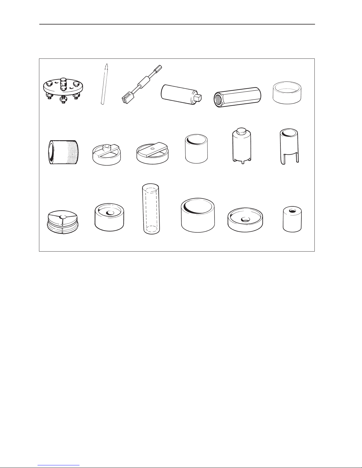
Special tools
884724-6 Hook wrench. Removal, assembly of
nuts.
884725-3 Drift Removal, assembly of retention ring
halves.
884726-1 Expanding mandrel. Removal of outer
bearing race.
884728-7 Drift Removal of bearings, gear wheels.
884729-5 Drift Installation of bearing.
884730-3 Drift Disassembly of output bearing hous-
ing.
884731-1 Drift Installation of bearing.
884732-9 Drift Installation of bearing.
884721 884723884720
884264884161884143
884732884726
884078
884725
884728
884611
884731
884730884729
884724
884637
884679
11
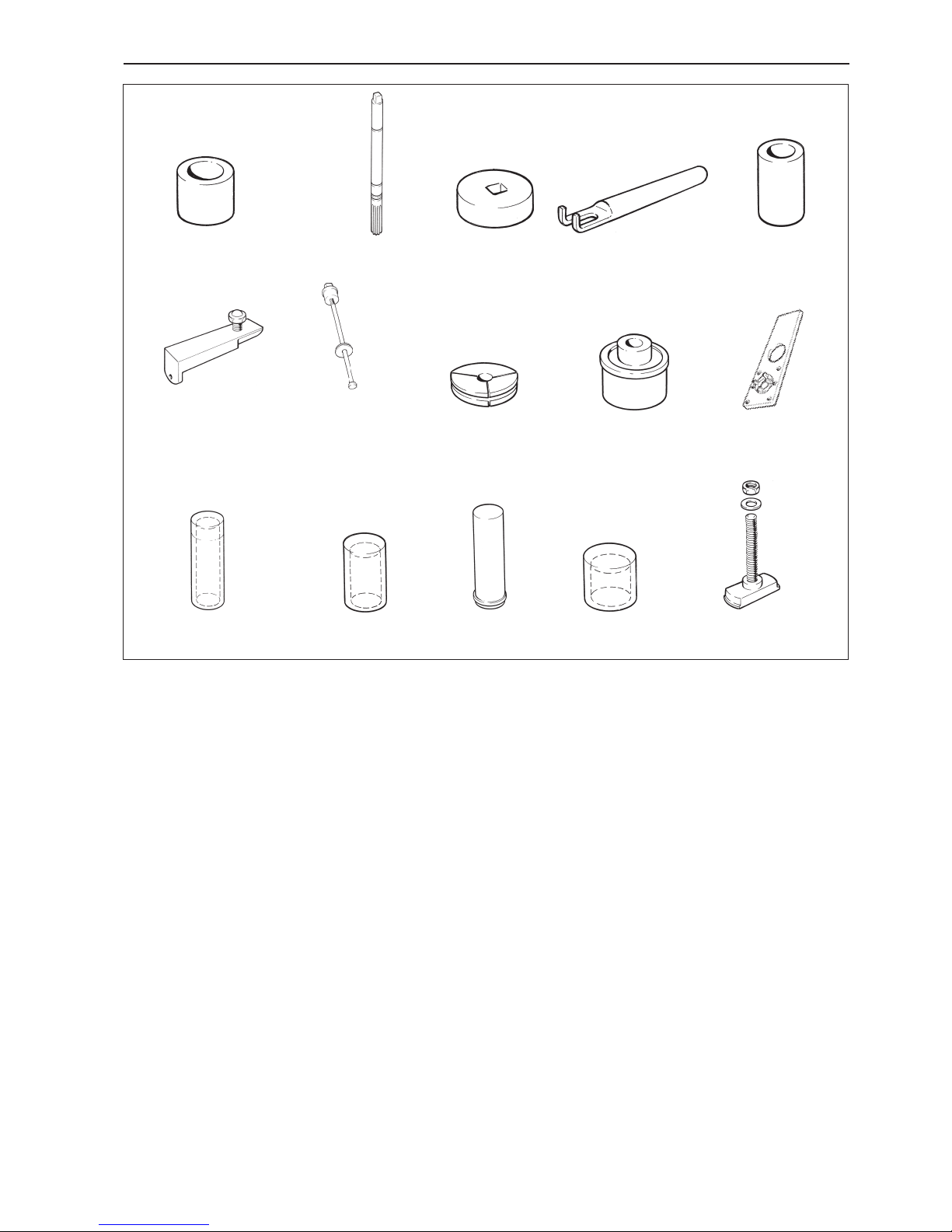
Special tools
884733-7 Drift. Installation of bearings, removal of
gear wheels.
884735-2 Tool. Checking of marking pattern.
884736-0 Wheel. For checking pre-load.
884738-6 Brake tool. Checking of marking pattern.
884739-4 Counterhold
884743-6 Removal of vertical shaft. Used together
with 884744 and 884745
884746-9 Installation of needle roller bearing. Used
together with 884747 and 884748
884750-1 Expanding mandrel. Removal of outer
bearing race.
884752-7 Drift. Installation of seal rings in rear
bearing housing.
884753-5 Fixture, 120S
884754-3 Drift. Installation of bearing.
884755-0 Drift. Installation of roller bearing, lower
gear housing.
884756-8 Drift. Installation of outer bearing race in
rear bearing housing.
884757-6 Drift. Installation of outer bearing race in
lower gear housing.
884761-8 Extractor. Used together with tool 884721
884743
884744
884745
884746
884747
884748 884750 884752 884753
884754 884755 884756 884757 884761
884735
884733
884736
884738
884739
12
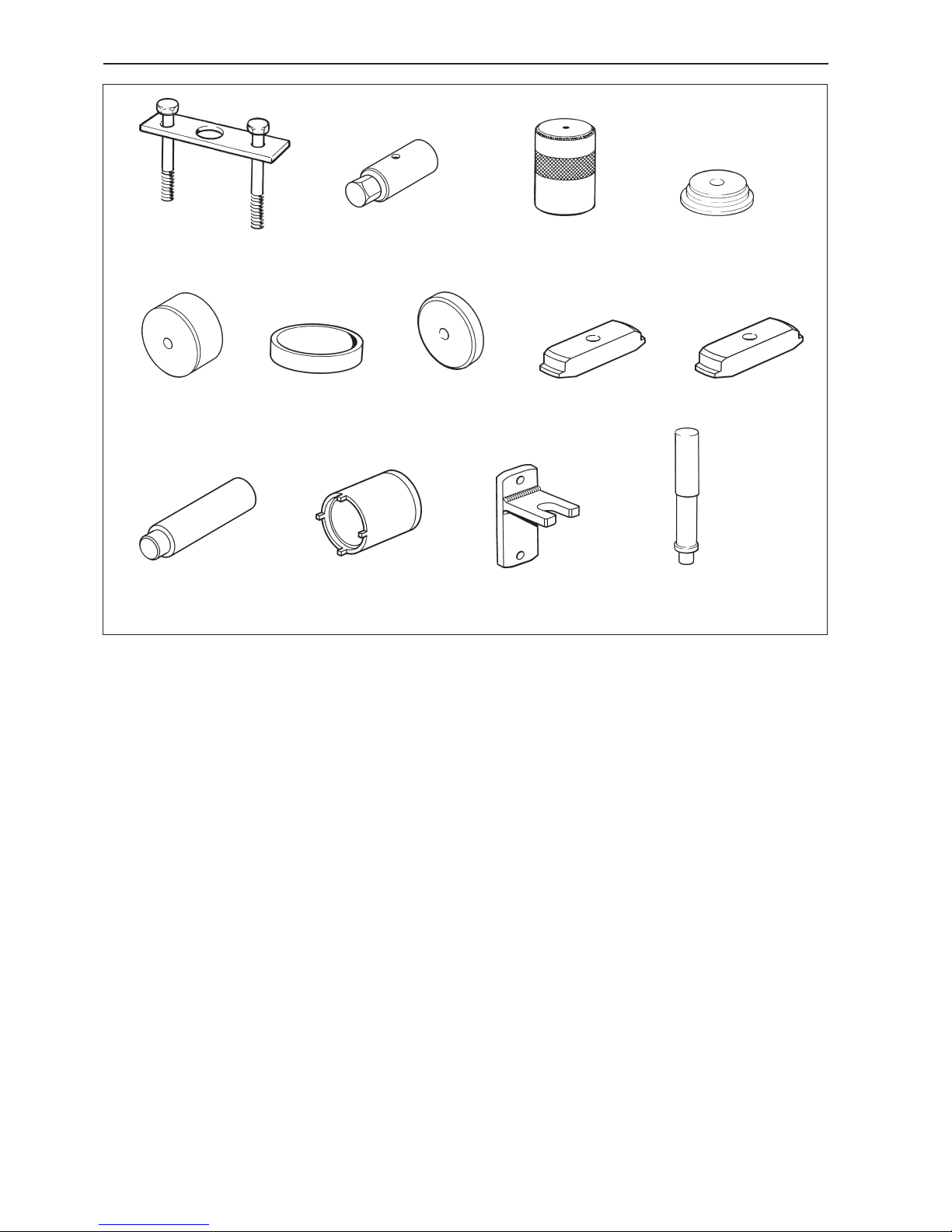
Special tools
884766-7 Press. For pressing down the vertical
shaft. Used together with 884753
884830-1 Sleeve for vertical shaft. Can be replaced
by 884264
884833-5 Drift. Installation of outer bearing race.
884833-5 Drift. Removal of bearing in cover, MS2V
884834-3 Plate. Installation of bearing race and
seal ring, MS2V
884835-0 Sleeve. Installation of rolling bearing on
tubular shaft, MS2V
884836-8 Ring. Installation of rolling bearing on pin-
ion, MS2V
884855-8 Plate. Installation of bearing race in cov-
er, MS2V
884856-6 Plate. Removal of bearing race from gear
housing, MS2V
884857-4 Plate. Removal of bearing race from cov-
er, MS2V
884859-0 Shaft, MS2V
884860-8 Hook wrench. Installation, removal of nut
on tubular shaft, MS2V
3858852-1 Counterhold. Removal of pinion nuts.
120S
9991801-3 Standard shaft
884833 884834
884835 884836 884855 884856 884857
884859 884860
884830884766
3858852 9991801
13
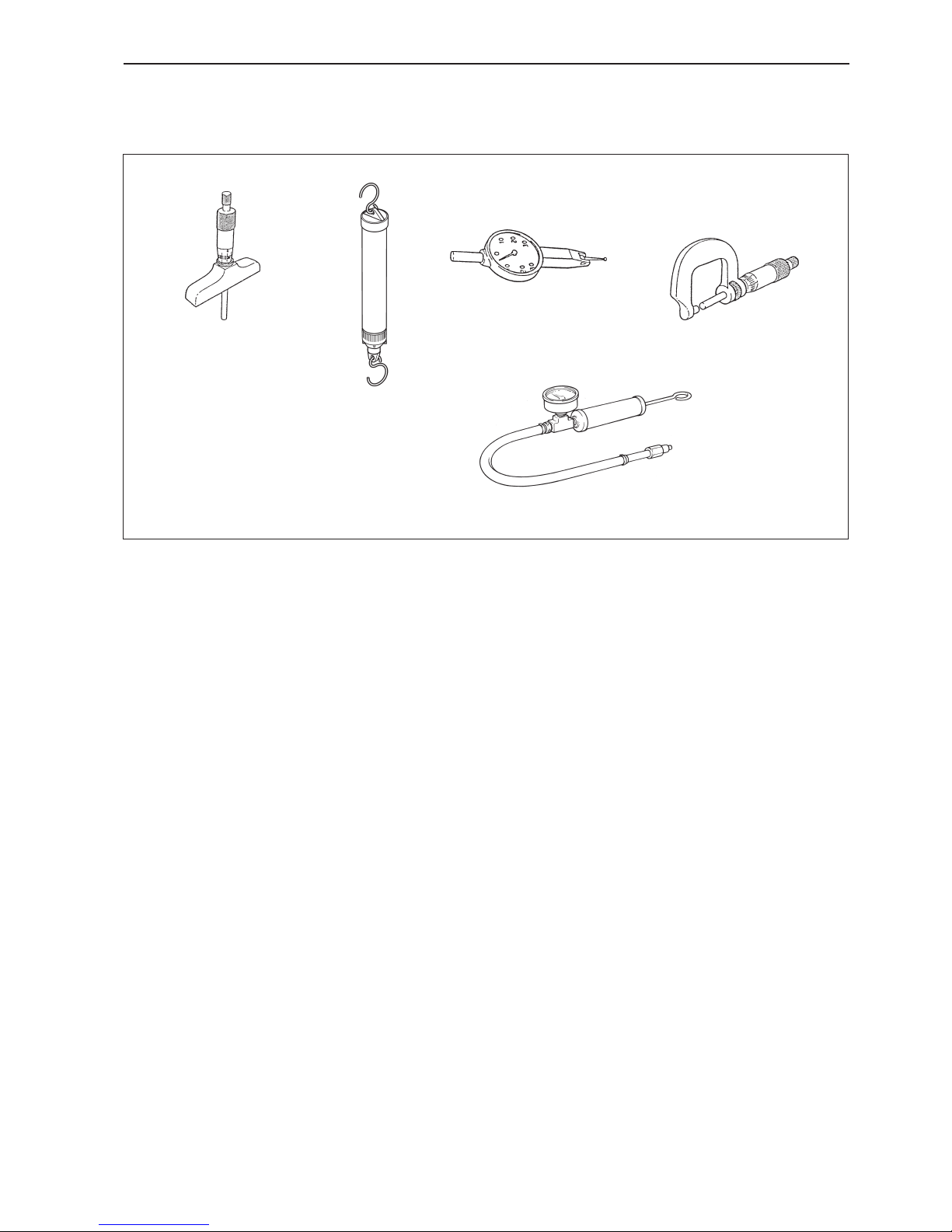
Other special equipment
9985472-1 Depth micrometer
9985494-5 Spring balance
9999683 -7 Dial gauge
9999701-7 Micrometer
3810152-3 Equipment for pressure testing drives
Chemicals
RTV preparations:
Volvo Penta part no. 840879-1, Loctite® 574;
Volvo Penta part no. 1161099-5, Permatex® No. 3.
Anaerobic preparations:
Volvo Penta part no. 1161053-2, Loctite® 243.
Polymer preparations:
Volvo Penta part no. 1141570-0 (white)
Water resistant grease:
Volvo Penta part no. 828250-1
9985472
9985494
9999683
9999701
3810152
14
Design and function
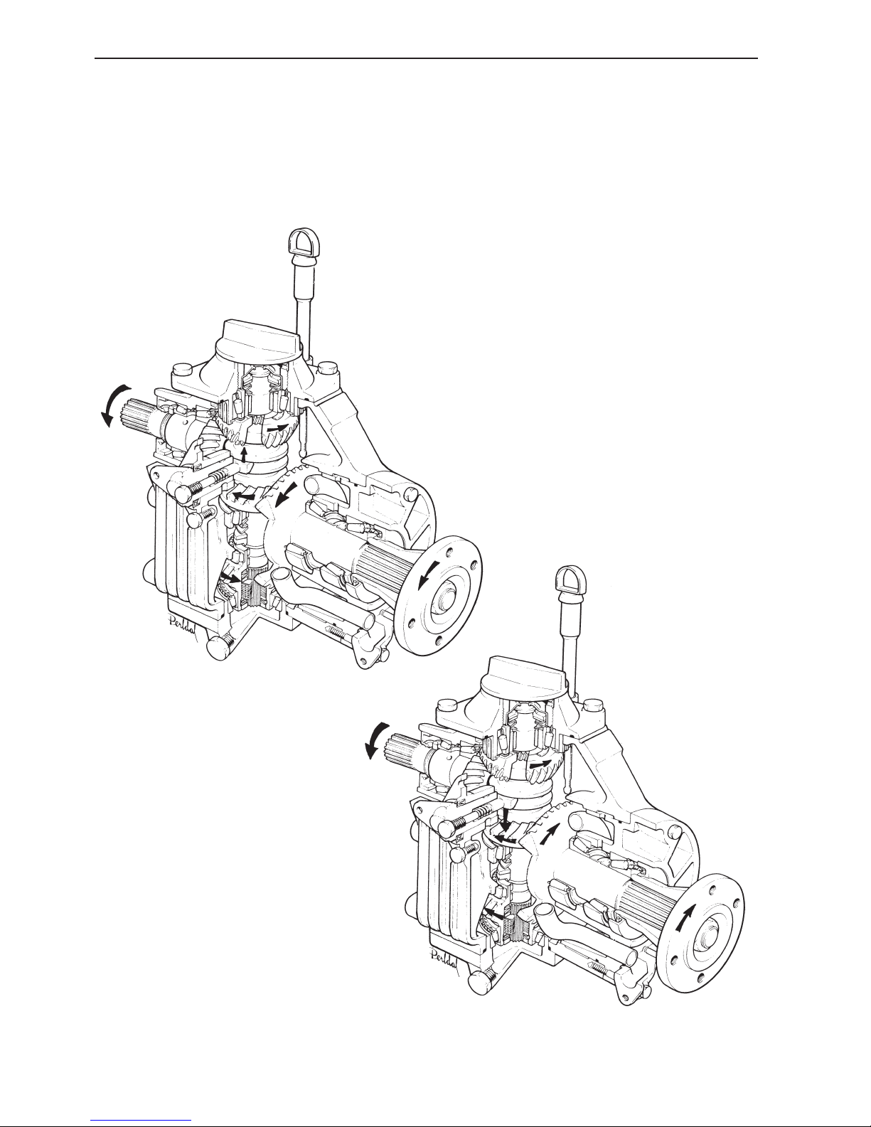
Reverse gear MS2
Forward position
Reverse position
15
Design and function
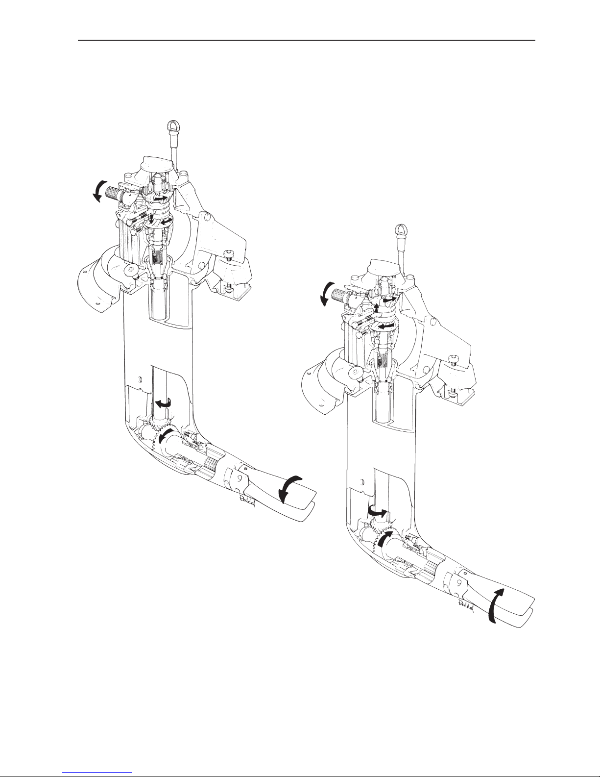
Sailboat drive 120S
Forward position
Reverse position
16
Design and function
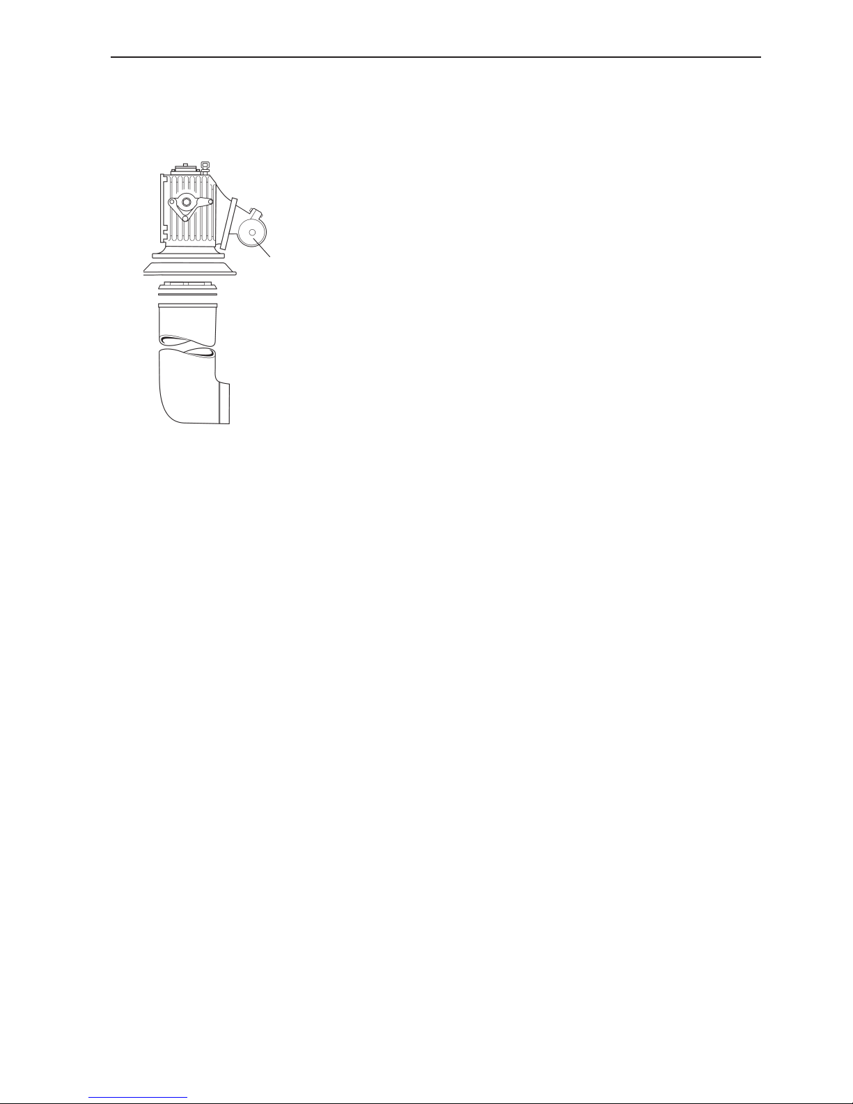
Model 120S-D
New material in sliding sleeve
New color, gray
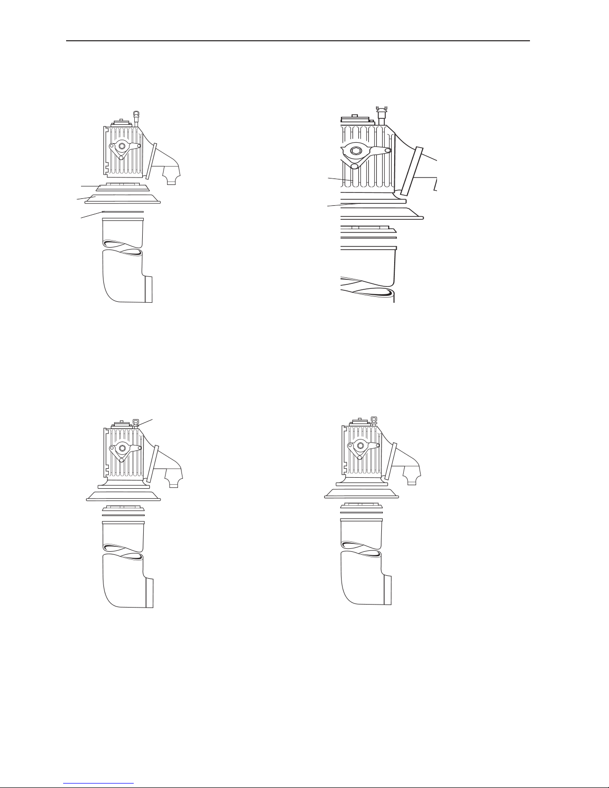
History, sail boat drives
Model 120S
Model 120S-B
Model 120S-C
3
2
1
1
2
1
1. Adapter, loose
2. Rubber sleeve
3. Gasket
1. Adapter, integrated into
gear housing
2. Adapter plate
1. Dipstick, new version
Production rationalization
changes
17
Design and function
1
Model 120S-E
1. Rubber mounting, new version
Shot blasted gear wheels
Fully synthetic oil

18
Disassembly - upper and lower gear housings,
sailboat drive
1. Clean the outside of the reverse gear and drive.
Remove the drain plug and drain the oil. Remove the
screws in the adapter section. Four socket cap
screws on the inside and two on the outside.
2. Remove the locking wire from the four screws.
Then remove all the screws, 10 pcs below the division
line of the drive.
Model 120S:
Also remove the four nuts on the front and rear of the
upper gear.
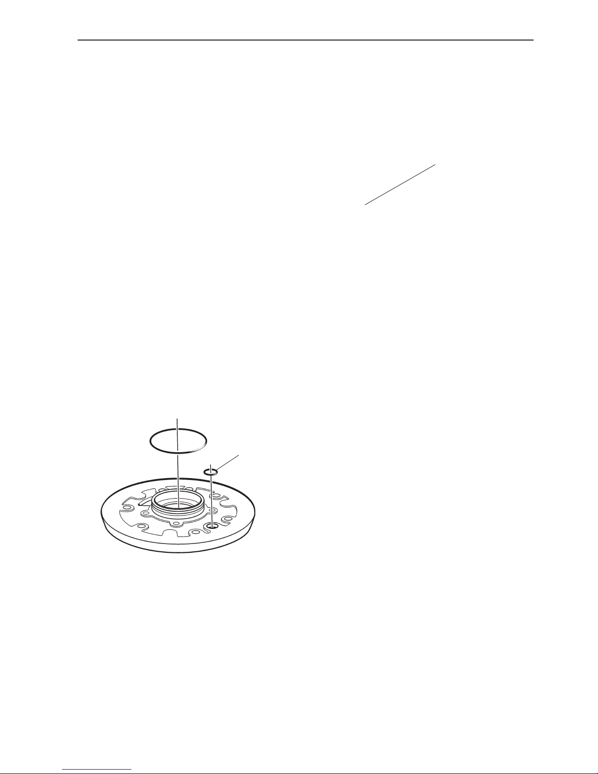
3. Split the drive and save the spacer ring (1), shims,
(2) and gasket (3).
Model 120S
Remove the rubber sleeve (4).
NOTE! The rubber sleeve must be changed every 5
years.
4. Model 120S
Remove the adapter section. Tap carefully with a
plastic or rubber faced mallet. Change the O-ring (1).
1
3
4
2
1
19
Disassembly - upper and lower gear housings, sailboat drive
5. Models 120S-B, -C, -D, -E
Remove the adapter plate and remove the rubber
sleeve.
Prize carefully. Use a tool with no sharp edges.
Remove and scrap the O-ring on the sleeve of the
adapter plate.
Repair of the lower gear housing, please refer to page
61.
Reverse installed drive (180°)
Remove and scrap the O-ring (1) on the adapter plate.
1
1
6. Remove the slipping clutch (1).
Check that the clutch is not damaged.

20
Repair - MS2 reverse gear and
upper gear housing, sailboat drive
Gear shift mechanism,
disassembly
1. Disassemble the gear shift mechanism, 2 screws.
2. Remove the dog (1) and spring (2).
3. Drive in the spring pin so far that the pin (1) is re-
leased.
4. Pull the pin out.
1
1
2

21
Repair - MS2 reverse gear and upper gear housing, sailboat drive
5. Pull the eccentric piston out.
6. Shake the pin out of the eccentric piston.
7. Remove the seal ring with a screwdriver. Clean all
components of the gear shift mechanism and check
for wear. Change components as necessary.
Gear shift mechanism,
assembly
8. Oil all components before assembly starts. Install
the seal ring. Align the side with the spring inwards.
Use tool no. 884679 or a pipe whose diameter is
slightly smaller than the outer diameter of the seal
ring.
9. Install the eccentric piston (1) and press the pin (2)
in. Lock it with the spring pin (3).
884679
1
2
3

22
Repair - MS2 reverse gear and upper gear housing, sailboat drive
11. Put the gear shift mechanism in a position between forwards and neutral. The pin should rest in one
of the “notches”.
12. NOTE! During assembly, the dog must be aligned
as shown in the illustration. The gear shift mechanism
will not work if the dog is turned the other way round.
13. Undo screw (1) about 2 turns and install the gear
shift mechanism in the housing. Check the position of
the dog. The screw must be displaced backwards, i.e.
to the right in the illustration.
Disassemble the screw, remove the shim and re-tighten the screw. It will now be impossible to turn the output shaft round.
Install one shim at a time until the shaft can be turned
without resistance.
After adjustment, apply sealant with Volvo Penta part
no. 1141570-0 to the shims and screw, then tighten
the screw.
10. Put a new O-ring (1) on the gear shift mechanism.
Install the spring (2) and dog (2).
1
3
2
1

23
Repair - MS2 reverse gear and upper gear housing, sailboat drive
Reverse gear/upper gear
housing, disassembly
14. Disassemble the double bearing seal housing, 6
screws.
NOTE! Tap carefully with a plastic-faced mallet etc.
Do not use a screwdriver to prize between the housing
and the bearing seal housing. This can damage the
sealing surface.
Save the shims.
15. Reverse gear MS2.
Disassemble the rear bearing housing. 6 screws. Also
tap carefully here with a plastic-faced mallet, until the
bearing housing comes away from the reverse gear.
Save the shims.
16. Drive, 120S, 120S-B, -C, -D, -E
Remove the cooling water valve.
Remove the gear shift cable holder and the rear cover
with rubber mounting.
Change the O-ring on the cover.
17. Unscrew the oil filler cap and remove the dipstick
and outer casing.
Model 120S
Also remove the throttle control bracket. The two front
screws on the bearing cover are removed later.

24
Repair - MS2 reverse gear and upper gear housing, sailboat drive
21. Remove the cover. A lock washer, a large spring
washer, three small spring washers and possibly one
or two spacers will come away with the cover. In addition, the ball bearing and gear wheel are fixed to the
cover.
NOTE! Remove the needle roller bearing. The bearing
might remain on the shaft.
18. Reverse gear MS2.
Turn the reverse gear upside down and remove the
bottom cover. 4 screws.
Scrap the O-ring.
19. Reverse gear MS2.
Remove the slipping clutch. Remove the sleeve bearing from the vertical shaft. In some cases, the bearing
might remain in the slipping clutch.
NOTE! If there is any fault in the slipping clutch, it
must be replaced as a unit. The clutch is only available as a complete spare part.
Change the roller bearing as necessary. Please refer
to items 73-83.
20. Turn the reverse gear/upper bearing housing over
and put it in a press. Put tool no. 884725 over the vertical shaft, so that it rests on the large washer. Press
the washer down, to release the retention ring halves.
Remove the halves.
884725

25
Repair - MS2 reverse gear and upper gear housing, sailboat drive
22. Pull up the sliding sleeve with a turning motion.
23. Reverse gear MS2
Press the outer bearing race out, using the vertical
shaft. Keep hold of the vertical shaft, to prevent it
from falling and being damaged. Save any shims beneath the bearing race.
NOTE! On the sailboat drive, the shaft is loose since
there are no bearings.
24. Put the vertical shaft in a press and press the
large washer with tool no. 884725, to release the retention ring halves. Remove the halves.
9991801
884733
1
2
3
4
5
884725
25. Remove the lock washer (1), the large domed
washer (2), the three smaller domed washers (3), any
spacer washers (4) and the needle roller bearing (5).
26. Press the gear wheel out. Use tool no. 884733 in
combination with standard shaft 9991801.
 Loading...