

Page 1

MS2, MS2B-A, MS2B-L, MS2A-D
MS2A-E, MS2L-D, MS2L-E, MS2V
120S, 120S-B, 120S-C, 120S-D, 120S-E
Workshop manual
2(0)
A
Page 2

Page 3

1
Reverse gear
MS2, MS2B-A, MS2B-L, MS2A-D
MS2A-E, MS2L-D, MS2L-E, MS2V
Sailboat drive
120S, 120S-B, 120S-C, 120S-D, 120S-E
Contents
Safety information ......................................................... 2
Introduction ................................................................. 2
Important .................................................................... 2
General information ...................................................... 5
About the workshop manual ........................................ 5
Spare parts ................................................................. 5
Repair instructions........................................................ 6
Our common responsibility .......................................... 6
Tightening torque ........................................................ 7
Torque-angle tightening ............................................... 8
Lock nuts .................................................................... 8
Strength classes ......................................................... 8
Sealants ..................................................................... 8
Safety rules for fluorocarbon rubber ........................... 9
Special tools ................................................................ 10
Other special equipment ............................................ 13
Chemicals .................................................................. 13
Design and function ..................................................... 14
History .......................................................................16
Disassembly - upper and lower gear housings
120S, 120S-B, -C, -D, -E ................................................18
Repair of MS2 reverse gear, upper gear housing
120S, 120S-B, -C, -D, -E ................................................20
Repair of MS2V reverse gear .......................................51
Repair - lower gear housing
120S, 120S-B, -C, -D, -E ................................................61
Pressure testing ......................................................... 80
Inspection and painting .............................................. 80
Technical data .............................................................. 81
References to Service Bulletins ..................................83
7752950-1 English 01-2001
Page 4
2
General instructions
Safety information
Introduction
The workshop manual contains technical data, descriptions and repair instructions for products or product versions noted in the table of contents, supplied
by Volvo Penta. Make sure you use the correct workshop literature.
Read the available safety information, “General information” and “Repair instructions” in the workshop manual before you start to do any service
work.
Important!
The following special warning signs are found in the
workshop manual and on the product.
WARNING! Warns for the risk of personal injury, major damage to product or property, or serious malfunctions if the instruction is ignored.
IMPORTANT! Is used to call attention to things
which could cause damage or malfunctions to
product or property.
NOTE! Is used to call attention to important information, to facilitate work processes or operation.
To give you a perspective on the risks which always
need to be observed and precautions which always
have to be taken, we have noted them below.
Make it impossible to start the engine by cutting
system current with the main switch(es) and
lock it (them) in the off position before starting
service work. Fix a warning sign by the helmsman’s seat.
All service work should normally be done on a
stationary engine. Some work, such as adjustments, need the engine to be running, however.
Going close to a running engine is a safety risk.
Remember that loose clothes, long hair etc. can
catch on rotating components and cause severe
injury.
If work is done adjacent to a running engine, a
careless movement or a dropped tool can lead
to personal injury in the worst case. Be careful
with hot surfaces (exhaust pipes, turbos, charge
air pipes, starting heaters etc.) and hot fluids in
pipes and hoses on an engine which is running
or which has just stopped. Re-install all guards
which have been removed during service work,
before re-starting the engine.
Make sure that the warning or information labels
on the product are always clearly visible. Replace labels which have been damaged or painted over.
Engines with turbocharger: Never start an engine without the air filter in place. The rotating
compressor turbine in the turbocharger can
cause severe injury. Foreign bodies in the inlet
pipe can also cause severe mechanical damage.
Never use start spray or similar products as a
starting aid. Explosions could occur in the inlet
manifold. Danger of personal injury.
Avoid opening the coolant filling cap (on fresh
water cooled engines) when the engine is hot.
Steam or hot coolant could spray out. Open the
filler cap carefully, and release the excess pressure in the cooling system. Be extremely careful
if a tap, plug or coolant hose has to be removed
from a hot engine. Steam or hot coolant can
stream out in an unexpected direction.
Hot oil can cause burns. Avoid skin contact with
hot oil. Make sure that the oil system is de-pressurized before doing any work on it. Never start
or run the engine with the oil filler cap removed,
because of the risk of oil spillage.
Stop the engine and close the sea cocks before
doing any work on the cooling system.
Only start the engine in a well-ventilated area.
When operated in a confined space, exhaust
fumes and crankcase gases must be ventilated
from the engine bay or workshop area.
Page 5
3
General instructions
Always use goggles when doing any work where
there is any risk of splinters, grinding sparks,
acid splash or other chemicals. Your eyes are
extremely sensitive, injury could cause blindness!
Avoid skin contact with oil! Long-term or repeated skin contact with oil can make your skin dry
out. The consequence is irritation, dry skin, eczema and other skin disorders. Used oil is more
hazardous to health than new oil. Use protective
gloves and avoid oil-soaked clothes and rags.
Wash regularly, especially before meals. Use
special skin cream to avoid drying and facilitate
skin cleaning.
Most chemicals intended for the product (e.g.
engine and transmission oils, glycol, petrol (gasoline) and diesel oil) or chemicals for workshop
use (e.g. degreasers, paints and solvents) are
hazardous. Read the instruction on the packages carefully! Always observe the safety advise
(e.g. use of breathing protection, goggles,
gloves etc.). Make sure that other personnel are
not inadvertently exposed to hazardous substances, such as via the air they breathe. Ensure good ventilation. Handle used and surplus
chemicals in the prescribed manner.
Be very careful when searching for leaks in the
fuel system and testing fuel injectors. Use goggles. The jet from a fuel injector is under very
high pressure, and has considerable penetration
ability; fuel can force its way deep into body tissues and cause serious injury. Risk of blood
poisoning (septicemia).
All fuels, and many chemicals, are flammable.
Make sure that open flames or sparks can not
set them alight. Petrol (gasoline), some thinners
and hydrogen gas from batteries are extremely
flammable and explosive when mixed with air in
the correct ratio. Do not smoke! Provide good
ventilation and take the necessary precautions
before you start welding or grinding in the vicinity. Always have a fire extinguisher easily available near the workplace.
Make sure that oil and fuel soaked rags, and
used fuel and oil filters are stored in a safe
place. Oil soaked rags can self-ignite in certain
circumstances. Used fuel and oil filters are polluting waste and must be handed to an approved
waste management facility for destruction, together with used lubrication oil, contaminated
fuel, paint residue, solvents, degreasers and
wash residue.
Batteries must never be exposed to open
flames or electric sparks. Do not smoke close
to the batteries. The batteries generate hydrogen gas when charged, which forms an explosive gas when mixed with air. This gas is very
flammable and highly explosive. A spark, which
can be formed if the batteries are wrongly connected, is enough to make a battery explode
and cause damage. Do not move the connections when you attempt to start the engine (risk
of arcing), and do not stand and lean over one of
the batteries.
Never mix up the battery positive and negative
poles when the batteries are installed. If the batteries are wrongly connected, this can cause severe damage to the electrical equipment. Please
check the wiring diagram!
Always use goggles when charging and handling
batteries. Battery electrolyte contains highly corrosive sulfuric acid. If this comes into contact
with your skin, wash at once with soap and a lot
of water. If you get battery acid in your eyes,
flush at once with a generous amount of water,
and get medical assistance at once.
Stop the engine and cut the system current with
the main switch(es) before doing any work on
the electrical system.
The clutch must be adjusted with the engine
shut off.
Page 6

4
General instructions
the lifting devise and other who makes sure that
components move freely and are not damaged
during lifting.
When you work aboard a boat, always make
sure that there is enough space for disassembly
where you are working, with no risk for personal
or material damage.
Components in the electrical system, the ignition system (on petrol (gasoline) engines) and
fuel systems on Volvo Penta products have
been designed to minimize the risks of explosion and fire. The engine must not be operated
in environments with adjacent explosive media.
Remember the following when washing with a
high pressure washer: Never aim the water jet at
seals, rubber hoses or electrical components.
Never use a high pressure washer for engine
cleaning.
NOTE! The fuel delivery pipes must not be bent,
twisted or tampered with in other ways. Change
damaged fuel delivery pipes.
Only use the fuels recommended by Volvo Penta. Please refer to the instruction book. The use
of fuel of inferior quality can damage the engine.
In a diesel engine, poor fuel can cause the regulation rod to bind and the engine will over-rev,
entailing a strong risk of personal injury and machinery damage. Poor fuel can also lead to higher maintenance costs.
The existing lugs on the engine/reverse gear
should be used for lifting. Always check that the
lifting devises are in good condition and that
they have the correct capacity for the lift (the
weight of the engine plus the reverse gear and
extra equipment if installed).
The engine should be lifted with a customized or
adjustable lifting boom for safe handling and to
avoid damaging components on top of the engine. All chains or cables should be parallel to
each other and should be as square as possible
to the top of the engine.
If other equipment connected to the engine has
altered its centre of gravity, special lifting devises may be needed to obtain the correct balance
and safe handling.
Never do any work on an engine which just
hangs from a lifting devise.
Never work alone when heavy components are
to be dismantled, even when safe lifting devises
such as lockable blocks & tackle are used.
Even when lifting devises are used, two people
are needed in most cases. One who operates
Page 7

5
General instructions
General information
About the workshop manual
This workshop manual contains technical data, descriptions and repair instructions for the MS2 reverse
gear, all versions, and sail boat drive 120S, all versions. The repair methods for the reverse gear and
drive (upper gear) are essentially the same. Where
they differ, this is noted.
In all correspondence, the product designation and serial number must be specified.
The workshop manual has been primarily prepared for
Volvo Penta service workshops and their qualified personnel. This assumes that people who use the Manual have basic knowledge of marine drive systems and
can do the tasks of a mechanical or electrical nature
associated with the trade.
Volvo Penta constantly improves its products, so we
reserve the right to make modifications without prior
notification. All information in this manual is based on
product data which was available up to the date on
which the manual was printed. Any material changes
introduced into the product or service methods after
this date are notified by means of Service Bulletins.
Spare parts
Spare parts for electrical and fuel systems are subject
to various national safety requirements such as the
US Coast Guard Safety Regulations. Volvo Penta
Original Spares comply with these requirements.
No damage whatever, occasioned by use of non-original Volvo Penta spares for the product, will be compensated by the warranty offered by Volvo Penta.
Page 8

6
General instructions
The work methods described in the workshop manual
apply to work in a workshop environment. For this reason, the reverse gear and drive are lifted out of the
boat.
The warning signs which occur in the workshop manual (please refer to “Safety information” for their meanings)
WARNING!
IMPORTANT!
NOTE!
are not comprehensive in any way, since we can not
foresee everything, since service work is done in highly varying circumstances. For this reason, all we can
do is to point out the risks which we believe could occur due to incorrect work in a well-equipped workshop,
using work methods and tools tested by us.
In the workshop manual, all tasks for which there are
Volvo Penta special tools, are done using these tools.
Special tools are specially prepared to permit the safest and most rational work methods possible. For this
reason, it is the responsibility of the person who uses
other tools or other work methods than those recommended by us, to ensure that there is no risk of personal injury or material damage, and that they can not
cause any malfunctions.
In some cases, special safety regulations and user instructions are available for the tools and chemicals
mentioned in the workshop manual. These rules must
always be observed, so there are no special instructions about this in the workshop manual.
The majority of risks can be prevented by taking certain elementary precautions and using common
sense. A clean workplace and a clean engine eliminate many risks of both personal injury and malfunction.
Above all, when work on fuel systems, lubrication
systems, induction systems, turbocharger, bearing
caps and seals is done, it is extremely important that
no dirt or other kinds of foreign particles are able to
get in, since this would otherwise cause malfunctions
or shortened repair life.
Our common responsibility
Each engine consists of a large number of collaborating systems and components. Any deviation of a
component from its technical specification can dramatically increase the environmental impact of an otherwise good engine. For this reason, it is extremely
important that specified wear tolerances are maintained, that systems with adjustment facilities are correctly adjusted and that Volvo Penta Original Spares
are used for the engine. The times noted in the engine
maintenance schedule must be observed.
Some systems, such as components in the fuel system, may require special competence and special test
equipment. For environmental reasons etc., some
components are sealed at the factory. It is only permissible to work on sealed components if you are authorized to do such work.
Remember that most chemical products, incorrectly
used, damage the environment. Volvo Penta recommends the use of biodegradable degreasers whenever
engine components are de-greased, unless otherwise
specified in the workshop manual. When working
aboard a boat, be careful to ensure that oils, wash
residue etc. are processed for destruction, and are not
inadvertently discharged with bilge water into the environment.
Repair instructions
Page 9

7
General instructions
Torque-angle tightening
In torque/angle tightening, the fastener is tightened to
the specified torque, and tightening then continues
through a pre-determined angle. Example: for 90° angle tightening, the fastener is turned a further 1/4 turn
in one sequence, after the specified tightening torque
has been achieved.
Lock nuts
Disassembled locknuts shall not be re-used, they
shall be replaced by new ones, since the locking properties are impaired or lost when the nut is used several times. On locknuts with plastic inserts, such as Nylock®, the tightening torque specified in the table must
be reduced if the Nylock® nut has the same nut height
as a standard fully metallic hexagonal nut. Reduce the
tightening torque by 25% if the screw dimension is 8
mm or greater. On Nylock® nuts with higher nut
height, where the fully metallic thread is as high as on
a standard hexagonal nut, use the tightening torques
in the table.
Strength classes
Screws and nuts are sub-divided into different
strength classes. Classification is indicated by markings on the screw head. A marking with higher number
indicates stronger material. For example, a screw
marked 10-9 is stronger than one marked 8-8. For this
reason, when fasteners are removed, it is important
that the screws are put back in the correct places
when they are re-installed. When you change screws,
please check the spare parts catalogue to ensure that
the correct versions are obtained.
Tightening torque
The tightening torques for vital fasteners, which
should be tightened with a torque wrench, are listed in
“Specifications: Tightening torque” and noted in the
job descriptions in the book. All torque specifications
apply to clean screws, screw heads and mating faces.
The torque specifications apply to lightly oiled or clean
screws. If lubricants, locking fluids or sealants are
needed on a fastener, the type of preparation to be
used will be noted in the job description and in “Tightening Torques”. Where a particular torque value is not
specified for any fastener, the general tightening
torques in the table below shall apply. The torque
specification is a target value and the fastener does
not need to be tightened with a torque wrench.
Dimension Tightening torque
Nm lbf ft
M5 6 4.4
M6 10 7.4
M8 25 18.4
M10 50 36.9
M12 80 59.0
M14 140 103.3
Page 10

8
General instructions
Sealants
Several different types of sealant and locking fluids
are used on the engine. The properties of the preparations differ, and they are intended for different
strengths of fastener, temperature, resistance to oil
and other chemicals, and for the different materials
and gap thicknesses found in the engine.
It is therefore important that the correct types of sealant and locking fluids are used on the fasteners where
needed, to give a fully acceptable service result.
In the workshop manual, the relevant chapters contain
notes on the preparations used in our production.
In service work, the same preparations or preparations
of corresponding properties, but of other makes, shall
be used.
When sealants and locking fluids are used, it is important that the surfaces are free from oil, grease, paint
and rust-protection, and that they are dry.
Always observe the manufacturer’s instructions about
temperatures of use, hardening times and other instructions for use of the product.
Various basic types of preparation are used, characteristics are as follows:
RTV preparations (Room Temperature Vulcanizing).
These are mostly used together with gaskets, such as
sealing gasket joints, or are brushed on gaskets. RTV
preparations are fully visible when the component has
been disassembled; old RTV compound must be removed before the joint is sealed again.
The following RTV preparations are mentioned in the
workshop manual: Volvo Penta part no. 840879-1,
Loctite® 574; Volvo Penta part no. 1161099-5, Permatex® No.3. Remove old sealant with denatured alcohol
in all cases.
Anaerobic preparations
These preparations harden in the absence of air.
These preparations are used when two solid components, such as two cast components, are fitted together without a gasket. Common uses are also to
lock and seal plugs, stud threads, taps, oil pressure
monitors etc. Hardened anaerobic preparations are
glassy and for this reason, the preparations are colored to make them visible. Hardened anaerobic preparations are highly resistant to solvents, and old compound can not be removed. On re-installation, degrease carefully and then apply new sealant.
The following anaerobic preparations are mentioned in
the workshop manual:
Volvo Penta part no. 1161053-2, Loctite® 243.
The following polymer preparations are mentioned in
the workshop manual:
Volvo Penta part no. 1141570-0 (white)
NOTE! Loctite® is a registered trademark belonging to the Loctite
Corporation, Permatex® is a registered trademark belonging to the
Permatex Corporation.
Page 11

9
General instructions
Safety rules for fluorocarbon
rubber
Fluorocarbon rubbers are commonly used materials in
seal rings on shafts, O-rings etc.
When flourocarbon rubber compounds are exposed to
high temperatures (above 572°F), hydrofluoric acid
can be formed, which is highly corrosive. Skin contact
can cause severe chemical burns. If it splashes in
your eyes, this can cause severe chemical burns. If
you breathe the fumes, you can suffer lung and bronchial injury.
WARNING! Be very careful when working on
engines which have been exposed to high temperatures, such as overheating caused by a seizure or fire. Seals must never be cut with a
flame torch during disassembly, or burned in uncontrolled circumstances afterwards.
• Always use chloroprene rubber gloves (gloves for
chemicals handling) and goggles.
• Handle the removed seal in the same way as corrosive acid. All residues, including ash, can be
strongly corrosive. Never use compressed air to
blow components clean.
• Put the remains in a plastic container, seal it and
apply a warning label. Wash the gloves under running water before you take them off.
The following seals are most probably made from fluorocarbon rubber:
Seal rings for the crankshaft, camshaft, drive shafts.
O-rings, irrespective of where they are installed.
O-rings for cylinder liner sealing are almost always
made of fluorocarbon rubber.
Please note that seals which have not been exposed to high temperature can be handled normally.
Page 12
10
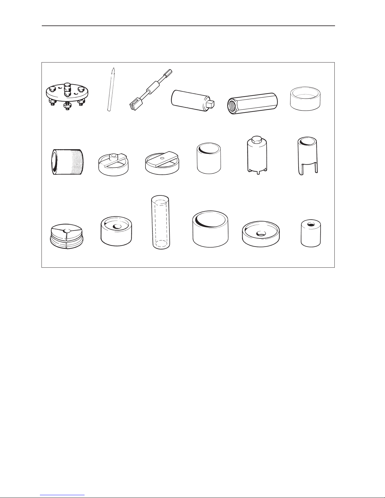
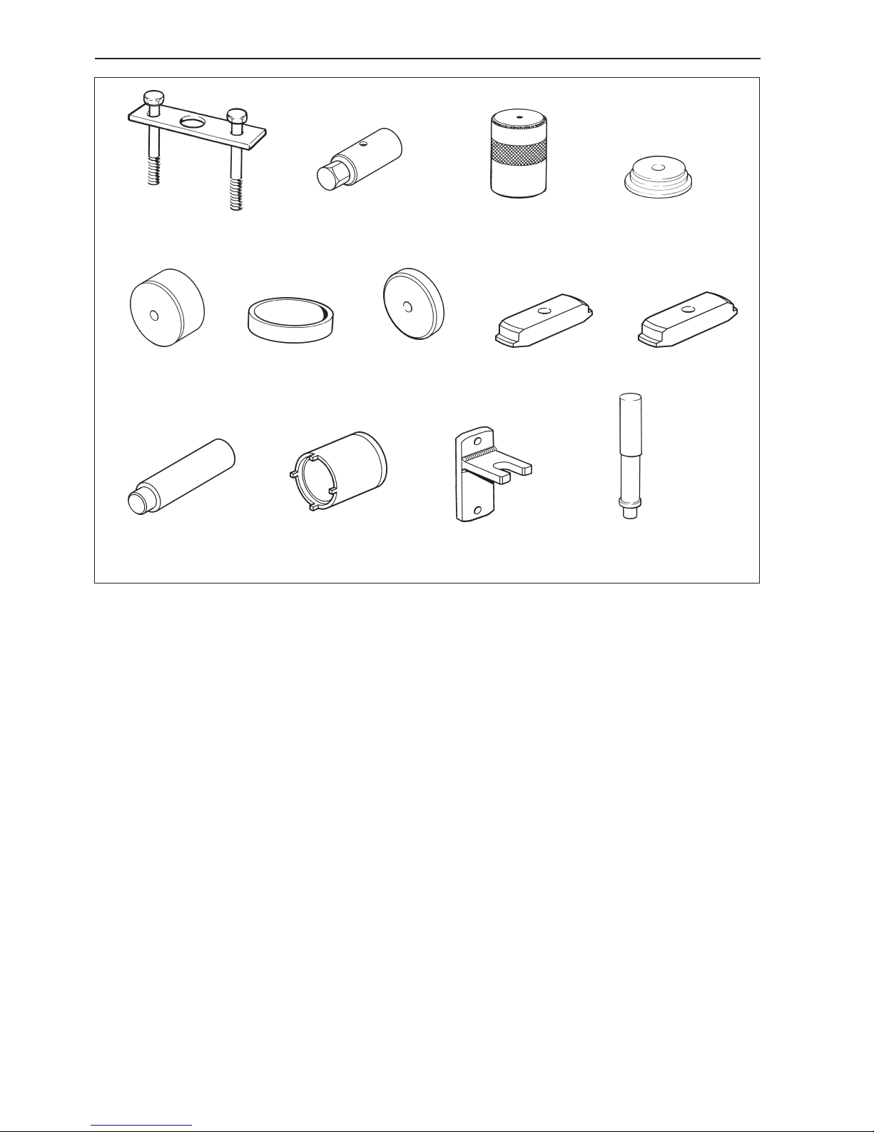
884078-7 Extractor. Disassembly of output shaft
884143-9 Shaft for expander 884750.
884161-1 Slide hammer. Removal of propeller shaft
884264-3 Sleeve for vertical shaft. Can be replaced
by 884830
884611-5 Extractor. Used together with 884161
884637-0 Sleeve. Disassembly of tubular shaft
MS2V
884679-2 Drift Installation of seal ring
884720-4 Extractor. Removal of outer bearing race.
Used together with 884761
884721-2 Extractor. Removal of outer bearing race.
Used together with 884761
884723-8 Drift Splitting of rear bearing housing
Special tools
884724-6 Hook wrench. Removal, assembly of
nuts.
884725-3 Drift Removal, assembly of retention ring
halves.
884726-1 Expanding mandrel. Removal of outer
bearing race.
884728-7 Drift Removal of bearings, gear wheels.
884729-5 Drift Installation of bearing.
884730-3 Drift Disassembly of output bearing hous-
ing.
884731-1 Drift Installation of bearing.
884732-9 Drift Installation of bearing.
884721 884723884720
884264884161884143
884732884726
884078
884725
884728
884611
884731
884730884729
884724
884637
884679
Page 13
11
Special tools
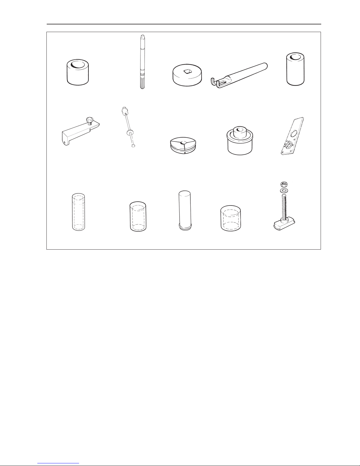
884733-7 Drift. Installation of bearings, removal of
gear wheels.
884735-2 Tool. Checking of marking pattern.
884736-0 Wheel. For checking pre-load.
884738-6 Brake tool. Checking of marking pattern.
884739-4 Counterhold
884743-6 Removal of vertical shaft. Used together
with 884744 and 884745
884746-9 Installation of needle roller bearing. Used
together with 884747 and 884748
884750-1 Expanding mandrel. Removal of outer
bearing race.
884752-7 Drift. Installation of seal rings in rear
bearing housing.
884753-5 Fixture, 120S
884754-3 Drift. Installation of bearing.
884755-0 Drift. Installation of roller bearing, lower
gear housing.
884756-8 Drift. Installation of outer bearing race in
rear bearing housing.
884757-6 Drift. Installation of outer bearing race in
lower gear housing.
884761-8 Extractor. Used together with tool 884721
884743
884744
884745
884746
884747
884748 884750 884752 884753
884754 884755 884756 884757 884761
884735
884733
884736
884738
884739
Page 14
12
Special tools
884766-7 Press. For pressing down the vertical
shaft. Used together with 884753
884830-1 Sleeve for vertical shaft. Can be replaced
by 884264
884833-5 Drift. Installation of outer bearing race.
884833-5 Drift. Removal of bearing in cover, MS2V
884834-3 Plate. Installation of bearing race and
seal ring, MS2V
884835-0 Sleeve. Installation of rolling bearing on
tubular shaft, MS2V
884836-8 Ring. Installation of rolling bearing on pin-
ion, MS2V
884855-8 Plate. Installation of bearing race in cov-
er, MS2V
884856-6 Plate. Removal of bearing race from gear
housing, MS2V
884857-4 Plate. Removal of bearing race from cov-
er, MS2V
884859-0 Shaft, MS2V
884860-8 Hook wrench. Installation, removal of nut
on tubular shaft, MS2V
3858852-1 Counterhold. Removal of pinion nuts.
120S
9991801-3 Standard shaft
884833 884834
884835 884836 884855 884856 884857
884859 884860
884830884766
3858852 9991801
Page 15
13
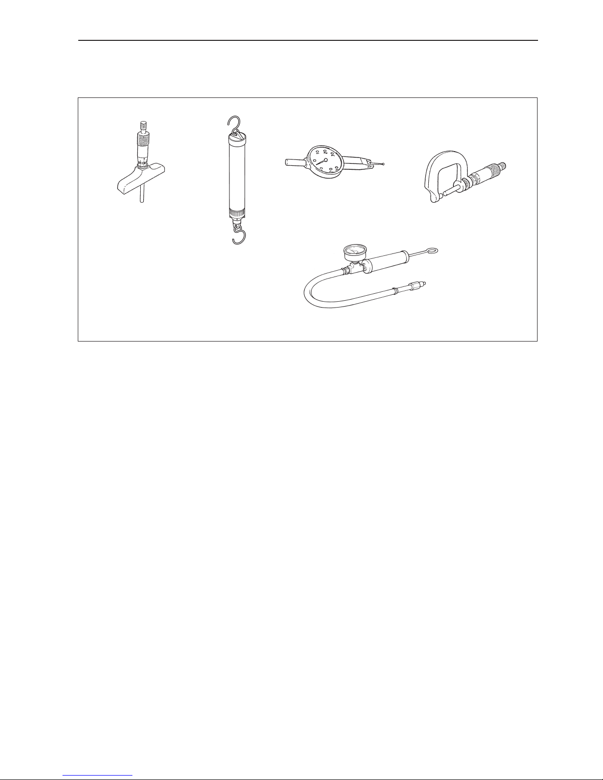
Other special equipment
9985472-1 Depth micrometer
9985494-5 Spring balance
9999683 -7 Dial gauge
9999701-7 Micrometer
3810152-3 Equipment for pressure testing drives
Chemicals
RTV preparations:
Volvo Penta part no. 840879-1, Loctite® 574;
Volvo Penta part no. 1161099-5, Permatex® No. 3.
Anaerobic preparations:
Volvo Penta part no. 1161053-2, Loctite® 243.
Polymer preparations:
Volvo Penta part no. 1141570-0 (white)
Water resistant grease:
Volvo Penta part no. 828250-1
9985472
9985494
9999683
9999701
3810152
Page 16
14
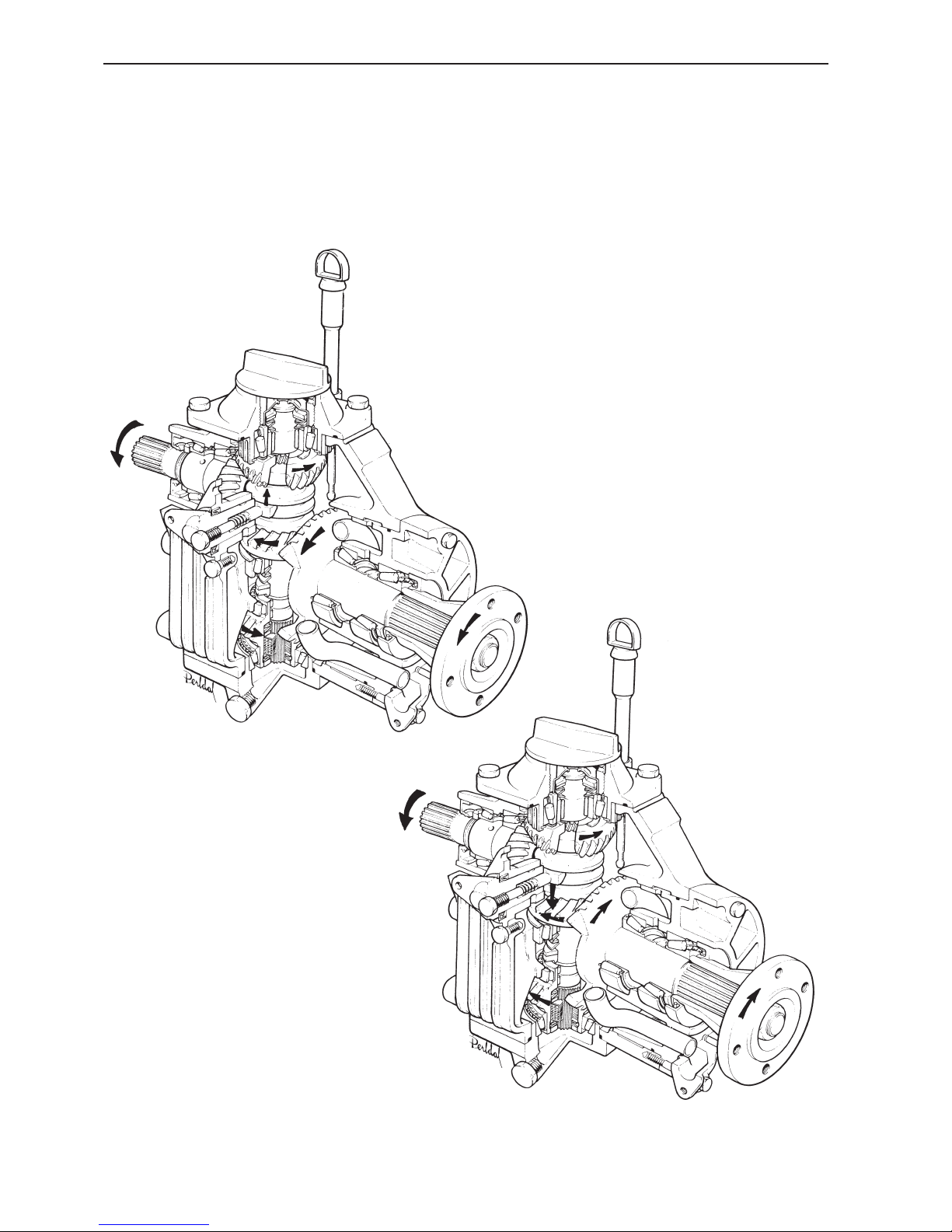
Design and function
Reverse gear MS2
Forward position
Reverse position
Page 17
15
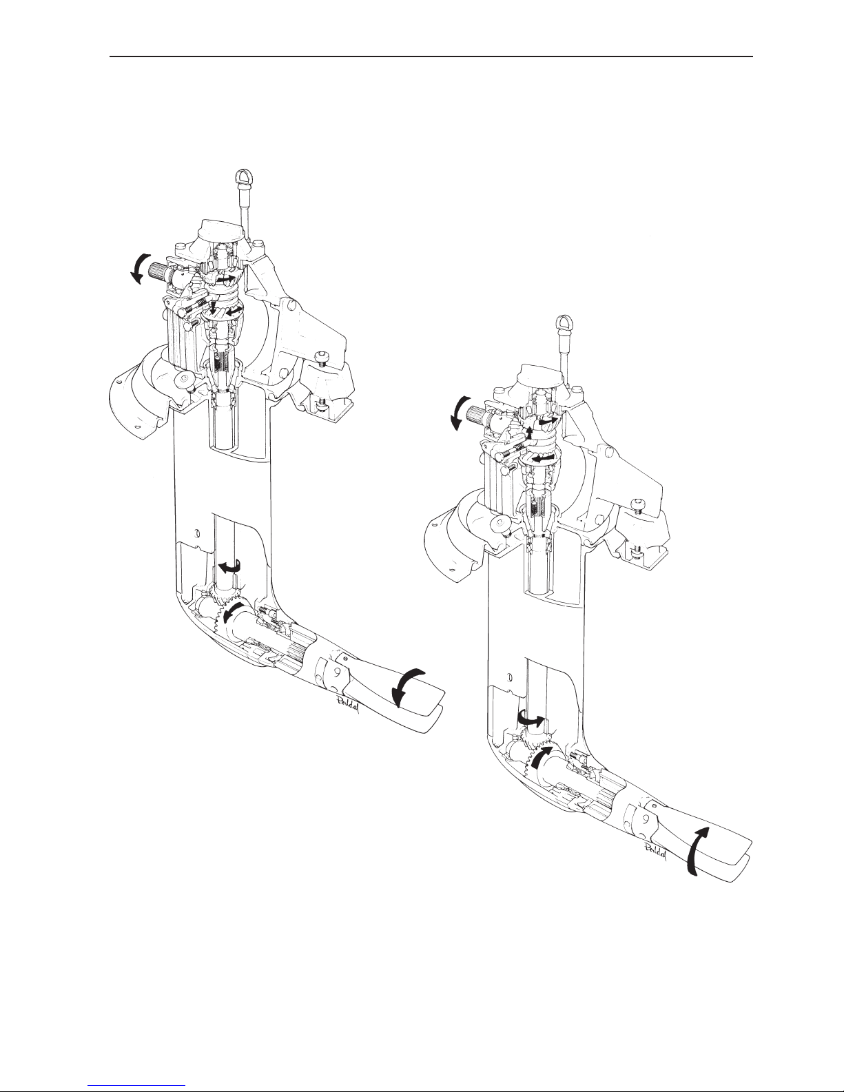
Design and function
Sailboat drive 120S
Forward position
Reverse position
Page 18
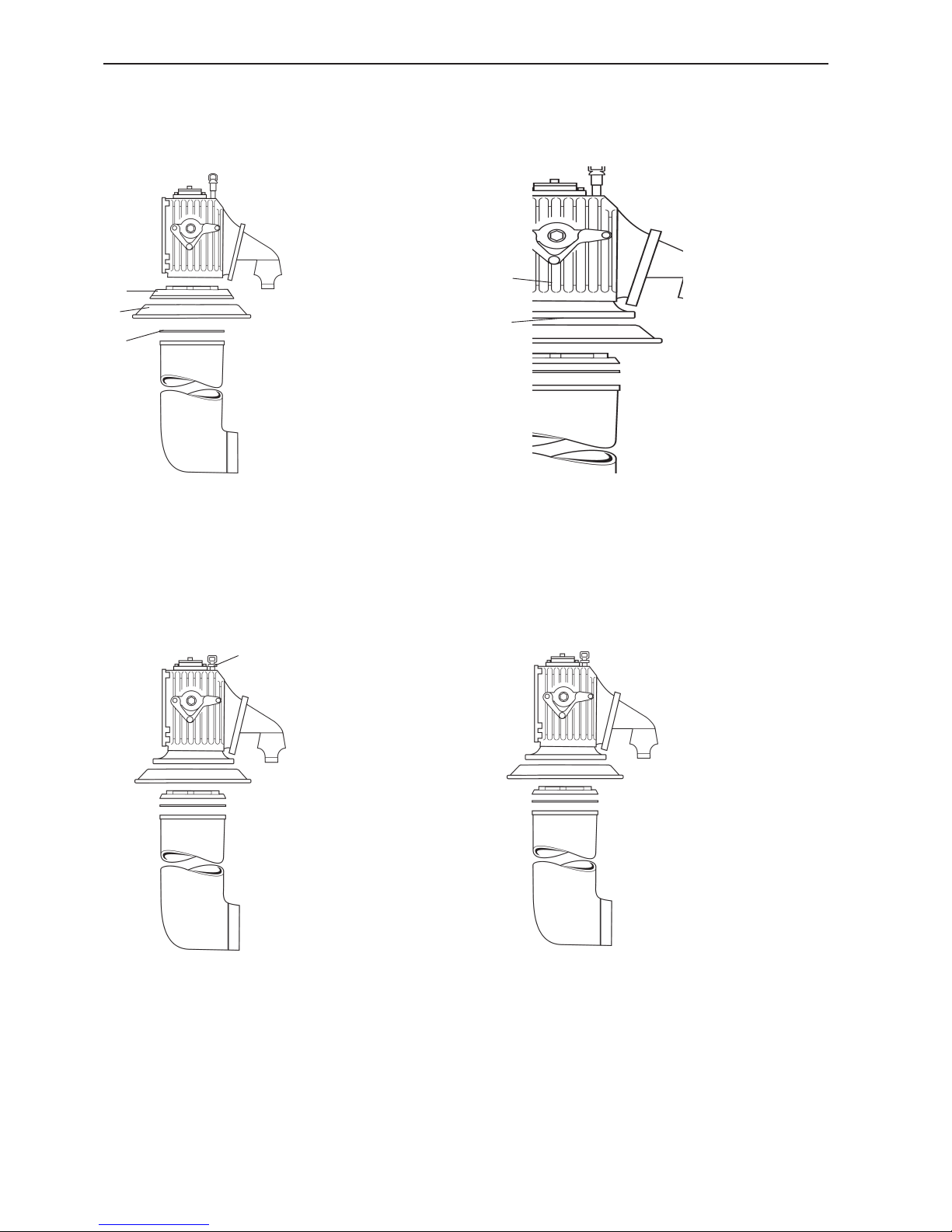
16
Design and function
Model 120S-D
New material in sliding sleeve
New color, gray
History, sail boat drives
Model 120S
Model 120S-B
Model 120S-C
3
2
1
1
2
1
1. Adapter, loose
2. Rubber sleeve
3. Gasket
1. Adapter, integrated into
gear housing
2. Adapter plate
1. Dipstick, new version
Production rationalization
changes
Page 19
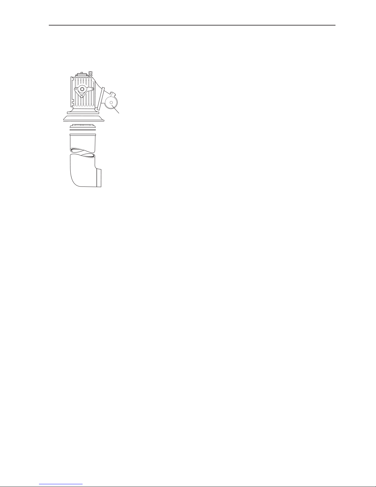
17
Design and function
1
Model 120S-E
1. Rubber mounting, new version
Shot blasted gear wheels
Fully synthetic oil
Page 20

18
Disassembly - upper and lower gear housings,
sailboat drive
1. Clean the outside of the reverse gear and drive.
Remove the drain plug and drain the oil. Remove the
screws in the adapter section. Four socket cap
screws on the inside and two on the outside.
2. Remove the locking wire from the four screws.
Then remove all the screws, 10 pcs below the division
line of the drive.
Model 120S:
Also remove the four nuts on the front and rear of the
upper gear.
3. Split the drive and save the spacer ring (1), shims,
(2) and gasket (3).
Model 120S
Remove the rubber sleeve (4).
NOTE! The rubber sleeve must be changed every 5
years.
4. Model 120S
Remove the adapter section. Tap carefully with a
plastic or rubber faced mallet. Change the O-ring (1).
1
3
4
2
1
Page 21
19
Disassembly - upper and lower gear housings, sailboat drive
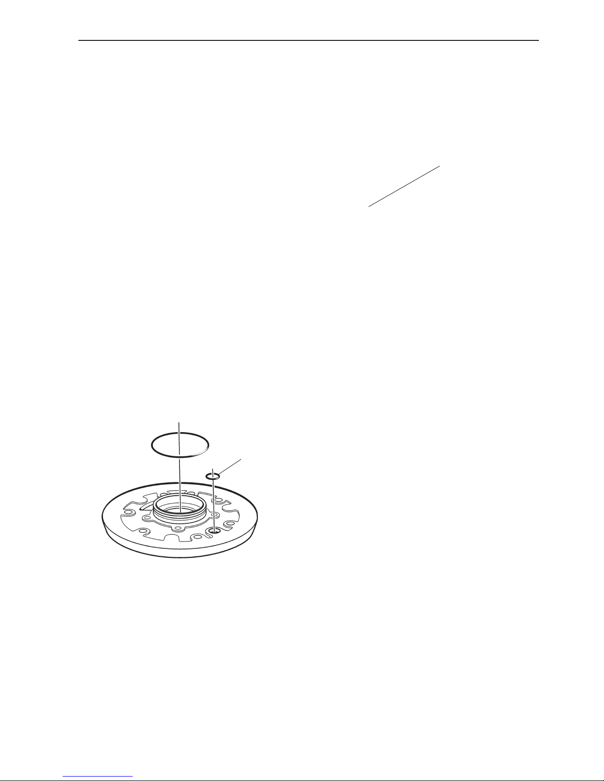
5. Models 120S-B, -C, -D, -E
Remove the adapter plate and remove the rubber
sleeve.
Prize carefully. Use a tool with no sharp edges.
Remove and scrap the O-ring on the sleeve of the
adapter plate.
Repair of the lower gear housing, please refer to page
61.
Reverse installed drive (180°)
Remove and scrap the O-ring (1) on the adapter plate.
1
1
6. Remove the slipping clutch (1).
Check that the clutch is not damaged.
Page 22

20
Repair - MS2 reverse gear and
upper gear housing, sailboat drive
Gear shift mechanism,
disassembly
1. Disassemble the gear shift mechanism, 2 screws.
2. Remove the dog (1) and spring (2).
3. Drive in the spring pin so far that the pin (1) is re-
leased.
4. Pull the pin out.
1
1
2
Page 23
21
Repair - MS2 reverse gear and upper gear housing, sailboat drive
5. Pull the eccentric piston out.
6. Shake the pin out of the eccentric piston.
7. Remove the seal ring with a screwdriver. Clean all
components of the gear shift mechanism and check
for wear. Change components as necessary.
Gear shift mechanism,
assembly
8. Oil all components before assembly starts. Install
the seal ring. Align the side with the spring inwards.
Use tool no. 884679 or a pipe whose diameter is
slightly smaller than the outer diameter of the seal
ring.
9. Install the eccentric piston (1) and press the pin (2)
in. Lock it with the spring pin (3).
884679
1
2
3
Page 24
22
Repair - MS2 reverse gear and upper gear housing, sailboat drive
11. Put the gear shift mechanism in a position between forwards and neutral. The pin should rest in one
of the “notches”.
12. NOTE! During assembly, the dog must be aligned
as shown in the illustration. The gear shift mechanism
will not work if the dog is turned the other way round.
13. Undo screw (1) about 2 turns and install the gear
shift mechanism in the housing. Check the position of
the dog. The screw must be displaced backwards, i.e.
to the right in the illustration.
Disassemble the screw, remove the shim and re-tighten the screw. It will now be impossible to turn the output shaft round.
Install one shim at a time until the shaft can be turned
without resistance.
After adjustment, apply sealant with Volvo Penta part
no. 1141570-0 to the shims and screw, then tighten
the screw.
10. Put a new O-ring (1) on the gear shift mechanism.
Install the spring (2) and dog (2).
1
3
2
1
Page 25

23
Repair - MS2 reverse gear and upper gear housing, sailboat drive
Reverse gear/upper gear
housing, disassembly
14. Disassemble the double bearing seal housing, 6
screws.
NOTE! Tap carefully with a plastic-faced mallet etc.
Do not use a screwdriver to prize between the housing
and the bearing seal housing. This can damage the
sealing surface.
Save the shims.
15. Reverse gear MS2.
Disassemble the rear bearing housing. 6 screws. Also
tap carefully here with a plastic-faced mallet, until the
bearing housing comes away from the reverse gear.
Save the shims.
16. Drive, 120S, 120S-B, -C, -D, -E
Remove the cooling water valve.
Remove the gear shift cable holder and the rear cover
with rubber mounting.
Change the O-ring on the cover.
17. Unscrew the oil filler cap and remove the dipstick
and outer casing.
Model 120S
Also remove the throttle control bracket. The two front
screws on the bearing cover are removed later.
Page 26

24
Repair - MS2 reverse gear and upper gear housing, sailboat drive
21. Remove the cover. A lock washer, a large spring
washer, three small spring washers and possibly one
or two spacers will come away with the cover. In addition, the ball bearing and gear wheel are fixed to the
cover.
NOTE! Remove the needle roller bearing. The bearing
might remain on the shaft.
18. Reverse gear MS2.
Turn the reverse gear upside down and remove the
bottom cover. 4 screws.
Scrap the O-ring.
19. Reverse gear MS2.
Remove the slipping clutch. Remove the sleeve bearing from the vertical shaft. In some cases, the bearing
might remain in the slipping clutch.
NOTE! If there is any fault in the slipping clutch, it
must be replaced as a unit. The clutch is only available as a complete spare part.
Change the roller bearing as necessary. Please refer
to items 73-83.
20. Turn the reverse gear/upper bearing housing over
and put it in a press. Put tool no. 884725 over the vertical shaft, so that it rests on the large washer. Press
the washer down, to release the retention ring halves.
Remove the halves.
884725
Page 27

25
Repair - MS2 reverse gear and upper gear housing, sailboat drive
22. Pull up the sliding sleeve with a turning motion.
23. Reverse gear MS2
Press the outer bearing race out, using the vertical
shaft. Keep hold of the vertical shaft, to prevent it
from falling and being damaged. Save any shims beneath the bearing race.
NOTE! On the sailboat drive, the shaft is loose since
there are no bearings.
24. Put the vertical shaft in a press and press the
large washer with tool no. 884725, to release the retention ring halves. Remove the halves.
9991801
884733
1
2
3
4
5
884725
25. Remove the lock washer (1), the large domed
washer (2), the three smaller domed washers (3), any
spacer washers (4) and the needle roller bearing (5).
26. Press the gear wheel out. Use tool no. 884733 in
combination with standard shaft 9991801.
Page 28

26
Repair - MS2 reverse gear and upper gear housing, sailboat drive
30. Fix the gear in a vise. Use soft facings on the vise
jaws. Then disassemble hook nut with tool no.
884724.
29. Fix the bearing housing in a vise. Press a screw-
driver into the seal ring. Then place a thick piece of
rubber or leather between the screwdriver and the
bearing housing casting. Prize out the seal ring and
scrap it.
9991801
884728
884724
Input bearing seal housing,
disassembly
27. Remove the circlip, using circlip pliers.
28. Press out the taper roller bearing. Use tool no.
884728 and standard shaft 9991801. Then wash the
gearbox housing out.
Page 29

27
Repair - MS2 reverse gear and upper gear housing, sailboat drive
884726
884143
884728
9991801
31. Drive or press the input shaft out of the bearing
housing. Use a plastic-faced mallet or similar, to avoid
damaging the end of the shaft and the splines.
32. If the roller bearings are damaged, they must be
changed. Remove the large outer bearing race from
the bearing housing, using tool no. 884726 and shaft
884143.
33. Drive out the small outer bearing race, using tool
884728 and shaft 9991801.
NOTE! Be careful to offer up the tool against the bear-
ing race.
34. Remove the roller bearing from the input shaft, using a knife-type extractor. Then remove the washer.
Clean the components and check for wear, replace
worn and damaged components.
Page 30

28
Repair - MS2 reverse gear and upper gear housing, sailboat drive
884729
9991801
884731
884732
1
35. Press the small outer bearing race into the bearing
housing. Use tool no. 884732.
36. Press the large outer bearing race into the bearing
housing. Use tool no. 884731 and shaft 9991801.
Input bearing housing,
installation.
37. Put the metal sheet (1) on the drive shaft.
38. Press the large roller bearing onto the drive shaft.
Use tool no. 884729.
Page 31

29
Repair - MS2 reverse gear and upper gear housing, sailboat drive
884724
884729
884757
9985494
2.25-4.05 lbf
39. Place the drive shaft in the bearing housing and
press the small roller bearing on, using tool no.
884729.
NOTE! Do not press the bearing until it bottoms. A
certain amount of clearance must be left. When the
nut is torqued to the correct value, the bearing housing is pre-loaded and the clearance disappears.
40. Screw a new nut on. Turn the chamfer inwards.
NOTE! The nut must always be changed.
Use tool no. 884724. Start off with low torque. Please
refer to the following chapter.
41. Test the pre-load with a spring balance. Fix the
gear wheel or shaft in a vise with soft jaw pads. Wind
a string round the bearing housing, and pull with spring
balance no. 9985494.
Pre-load: 10-18 N (2.25-4.05 lbf)
Not enough pre-load: Increase the torque on the nut.
Too much pre-load: Reduce the torque on the nut.
42. Oil and install the seal ring carefully, to avoid
damage to the seal lip. Use tool no. 884757 to drive
the ring in.
Page 32

30
Repair - MS2 reverse gear and upper gear housing, sailboat drive
Upper bearing housing,
disassembly
43. Put the bearing housing in tool no. 884723 and
press the gear wheel out. Use tool no. 884733 and
shaft 9991801. Save any shims.
44. Remove the circlip, using circlip pliers.
45. Put the bearing housing in tool no. 884723 and
press roller bearing out of the bearing housing. Use
tool no. 884728 and shaft 9991801.
884723
884733
9991801
884723
884728
9991801
Page 33

31
Repair - MS2 reverse gear and upper gear housing, sailboat drive
Upper bearing housing,
assembly
46. Press the upper roller bearing into the bearing
housing. Use tool no. 884731 and shaft 9991801.
NOTE! The narrow ring on the bearing, at the arrow,
should face the bearing housing. Make sure that the
bearing does not go in crookedly.
47. Install the circlip, using circlip pliers. Turn the
chamfered side down, towards the gear housing.
Make sure that the circlip is securely seated in the
groove.
48. Put shims on the gear wheels for the upper bearing housing and gear housing. Start off with 0.50 mm
for each gear wheel. This is a value which is based on
experience.
49. Press the gear wheel into the gear housing. Use
tool no. 884728, shaft 9991801 and 884739 as a support for the inner race.
9991801
884728
9991801
884731
884731
Page 34

32
Repair - MS2 reverse gear and upper gear housing, sailboat drive
Reverse gear MS2
Output gear housing,
disassembly
52. Remove the nut.
Socket size: 27 mm
53. Disassemble the propeller shaft flange. Use tool
no, 884078, wrench dimension 19 mm, or a claw pull-
er.
Pull the seal ring off the propeller shaft flange.
50. Press the gear wheel into the upper bearing housing. Use tool no. 884728, shaft 9991801 and 884739
as a support for the inner race.
51. Install the upper bearing housing on the reverse
gear.
884739
9991801
884728
884078
Page 35

33
Repair - MS2 reverse gear and upper gear housing, sailboat drive
55. Remove the seal ring. Use a screwdriver or similar
tool.
NOTE! Use rubber or leather to protect the edges of
the bearing housing.
Clean off all traces of sealant.
54. Press the output shaft out of the bearing housing.
Use tool no. 884730.
57. Remove the ferrule (1) from the output shaft.
884730
1
2
1
56. Remove the O-ring (1) and ball bearing (2) from
the bearing housing.
Page 36

34
Repair - MS2 reverse gear and upper gear housing, sailboat drive
58. Press the shaft out from the roller bearing. Use a
knife puller.
59. Remove the outer bearing races from the output
bearing housing. Use tool no. 884726 and shaft
884143.
60. Check that the cooling water pipe is in good condi-
tion. Change as necessary.
Remove the screw and lift the manifold off.
61. Remove the O-rings from around the cooling water
pipe and screw hole. The O-ring for the screw hole is
mounted on the screw.
Press the cooling water pipe out from the bearing
housing.
Clean off all traces of sealant.
884726
884143
Page 37

35
Repair - MS2 reverse gear and upper gear housing, sailboat drive
Reverse gear MS2
Output gear housing,
assembly
62. Install one of the outer bearing races in the bear-
ing housing. Use tool no. 884731 and shaft 9991801.
NOTE! Make sure that the bearing race does not go in
crookedly.
63. Turn the bearing housing over and press in the
other bearing race. Use tool no. 884731 and shaft
9991801.
64. Install the cooling water pipe and install the two
larger O-rings (1). Press the small O-ring (2) onto the
screw.
65. Apply sealant, Volvo Penta part. no. 840879-1 on
the mating face against the bearing housing.
Install the cooling water union. Check that the O-ring
is correctly aligned. Tighten the screw.
884731
9991801
884726
884731
1
2
Page 38

36
Repair - MS2 reverse gear and upper gear housing, sailboat drive
66. Press a roller bearing onto the output shaft. Use
tool no. 884729.
67. Install a new ferrule (1).
NOTE! Always use a new ferrule when the output
shaft has been removed from the housing.
68. Place the drive shaft in the bearing housing and
press the other roller bearing on, using tool no.
884729.
NOTE! Do not press the bearing until it bottoms.
Some clearance must be left. When the nut is torqued
to the correct value, the bearing housing is pre-loaded
and the clearance disappears.
69. Apply sealant, Volvo Penta part. no. 840879-1 on
the mating face of the seal ring against the bearing
housing.
Install the seal ring in the bearing housing. Press the
outer diameter of the seal with a mandrel.
Wipe some grease, Volvo Penta part no. 828250-1 on
the ring.
884729
1
884729
Page 39

37
Repair - MS2 reverse gear and upper gear housing, sailboat drive
70. Put on O-ring (1) and thread seal ring (2) on.
Install the propeller shaft flange and install a new nut.
Tighten the nut.
NOTE! Start off with low torque and check with a
spring balance. Please refer to item 71.
71. Use spring balance 9985494 to check that the correct pre-load has been obtained.
Pre-load: 8.5-16.0 N (1.91-3.60 lbf)
Tighten the nut progressively until the correct pre-load
has been obtained.
1
2
Reverse gear MS2
Lower bearing cover,
disassembly
72. Disassemble the outer bearing race with tool no.
884720.
Remove the shim and the O-ring.
1.91-3.60 lbf
9985494
Page 40
38
Repair - MS2 reverse gear and upper gear housing, sailboat drive
Reverse gear MS2. Slipping
clutch/lower bearing cover,
assembly
75. Press the small ball bearing onto the slipping
clutch. Use tool no. 884733.
76. Preferably use the shims which were installed pre-
viously, if only new bearings have been installed. In
other cases, the shim thickness can be calculated as
in items 77–84.
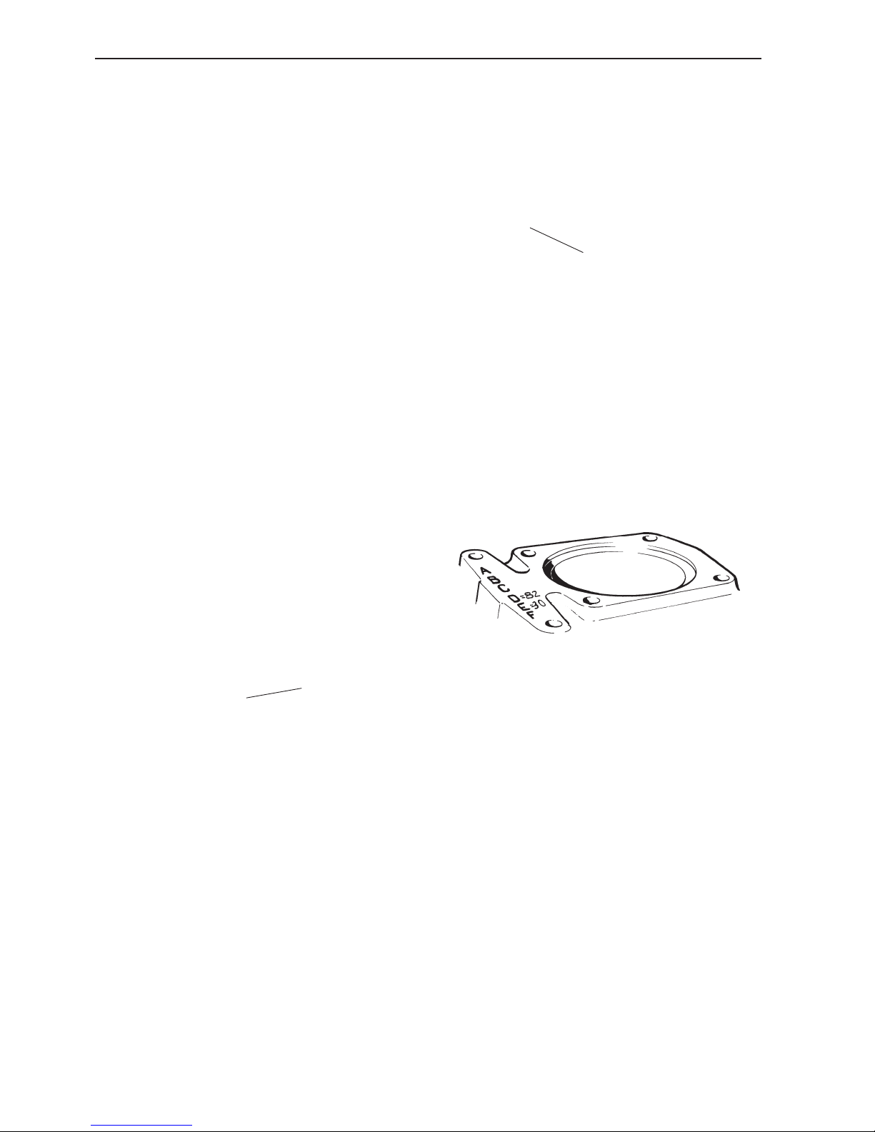
Calculate the shim thickness for the small bearing
race in the slipping clutch. The housing is stamped
with a D dimension and an E dimension.
Let us assume that the D dimension = 88.82 mm and
the E dimension = 61.30 mm.
NOTE! The D dimension is based on 88.00 and only
the decimals are stamped. The E dimension is based
on 61.00, to which the stamped value should be added.
Thus: 88 + 0.82 = 88.82 and 61.00 + 0.30 = 61.30.
The example below shows how the shim thickness is
calculated.
Example:
D = 88.82 NOTE! only 82 is stamped
E = 61.30 NOTE! only 30 is stamped
D–E = 27.52
884733
Reverse gear MS2
Slipping clutch,
disassembly
73. When the bearings need to be changed. Press the
small ball bearing off the slipping clutch. Use a mandrel and knife extractor.
74. Press the large ball bearing off the slipping clutch.
Use a knife extractor and tool no. 884729.
884729
Page 41
39
Repair - MS2 reverse gear and upper gear housing, sailboat drive
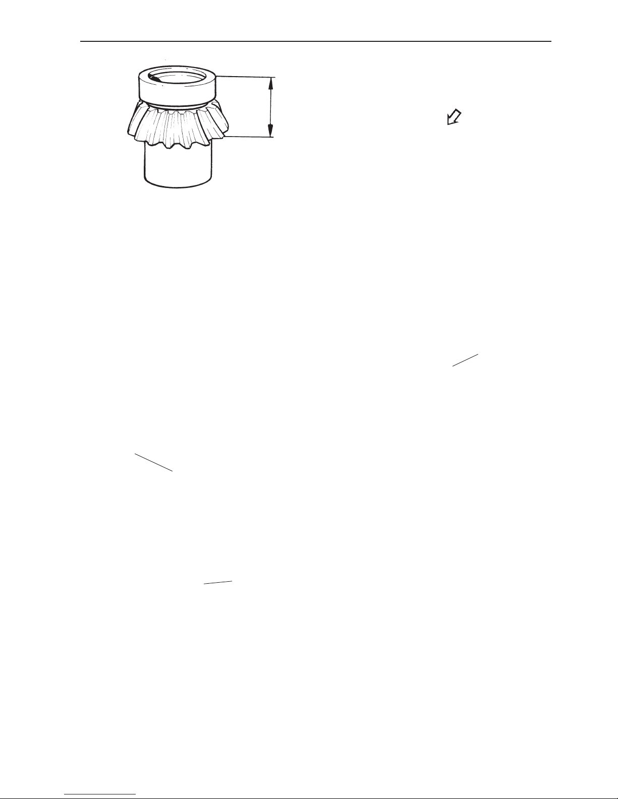
77. Assume that the marking on the gear wheel =
65.00 mm. Only 00 is stamped on the gear wheel.
Put the outer bearing race on and measure the depth
of the gear wheel and the small roller bearing, as
shown in the illustration. For example, 37.10 mm.
The marking on the gear wheel is 65.00 mm and we
have measured the gear wheel + bearing to 37.10
mm. This gives us 65.00–37.10 = 27.90 mm.
Since D–E = 27.52 mm, this gives the shim thickness
27.90–27.52 = 0.38 mm.
78. Press the large ball bearing onto the slipping
clutch. Use tool no. 884732 and tool no. 884733 under
the small gear wheel.
Use the original shims when only new ball bearings
have been installed. In other cases, the shim thickness must be calculated as in items 76–77.
79. Place the shims, as calculated, in the housing. In
this case, they are 0.40 mm.
80. Press the small bearing race into the housing. Use
tool no. 884732.
884732
884732
884732
Page 42
40
Repair - MS2 reverse gear and upper gear housing, sailboat drive
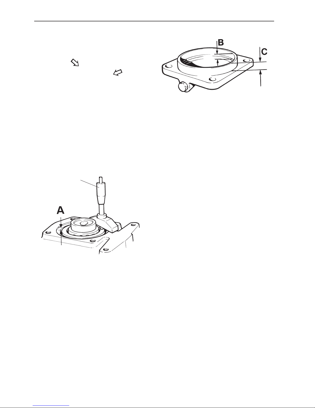
83. Measure the cover on the inside (B) down to the
shim seat. Then measure the cover on the outside
(C).
Example:
S = (C–B)–A, where S is the shim thickness.
First press the bearing race, and turn the gear wheel
about 10 turns. The ensuing measurement A becomes
2.5 mm, for example.
We now measure distance B, which becomes 16.05
mm, for example. We then measure distance C, which
becomes 18.10 mm, for example.
This gives: C–B = 18.10-16.05 = 2.05 mm.
This should be subtracted from the A dimension,
which we measured as 2.5 mm.
2.50 -2.05 = 0.45 mm
NOTE! To obtain the correct pre-load, shims with a
thickness of 0.45 + 0.05 = 0.50 mm should be put in
the cover.
81. Put the slipping clutch into the housing and place
the outer bearing race loose on top of the bearing.
82. Calculate the shim thickness as follows:
Press the outer bearing race with your fingers and turn
the gear wheel (pinion) round about 10 turns, to remove any slack in the rollers.
Measure with a depth micrometer 9985474 from the
housing plane, down to the bearing race (A).
9985474
Page 43

41
Repair - MS2 reverse gear and upper gear housing, sailboat drive
85. Install the cover on the housing, and tighten it with
four screws.
Reverse gear MS2
Flank clearance
86. Put an 0.20 mm shim on the outgoing bearing
housing, and install it on the housing.
87. Measure the flank clearance with a dial gauge and
rocker 9999683.
Flank clearance: 0.10-0.25 mm (0.004-0.010")
Adjust the flank clearance if necessary.
Not enough clearance:. Add more shims to the output bearing housing.
Not enough clearance:. Reduce the shim thickness
in the bearing housing.
84. Put in shims of the calculated thickness, plus a
further 0.5 mm in the cover and install the bearing
race. Put a plate on the bearing race and press.
NOTE! Align the bearing race carefully, to ensure that
it does not go in crookedly.
The extra shim thickness will be removed later, when
the flank clearance has been tested.
9999683
Page 44
42
Repair - MS2 reverse gear and upper gear housing, sailboat drive
Reverse gear MS2
Marking pattern
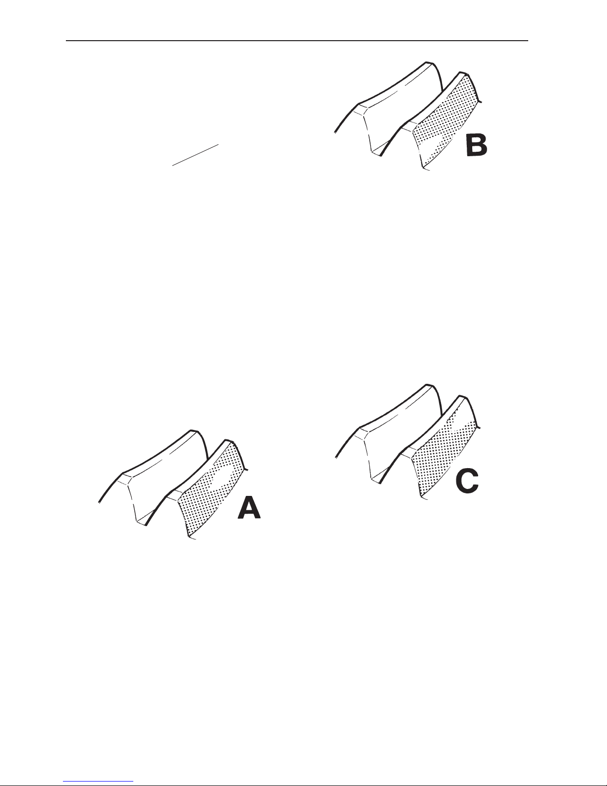
88. Remove the output bearing housing and apply a
thin layer of marking dye to the lower gear and the
gear wheel on the output shaft.
Install the bearing housing again and turn tool no.
884735 round in both directions, at the same time as
the propeller shaft flange is braked.
89. Remove the output bearing housing and check
whether the marking pattern on the gear wheel corresponds with marking pattern A, which is correct. The
pattern should be located at the centre of the tooth, in
height, but displaced towards the small end.
90. If the marking pattern is similar to B, the output
shaft must be moved inwards by removing shims from
the bearing housing.
If the flank clearance is too small after this operation,
the lower drive must be moved downwards by reducing the shim thickness underneath the bearing race in
the cover.
NOTE! To retain the preload in the lower gear wheel
bearing, the shim thickness for the upper bearing outer race must be increased to the same extent.
91. If the marking pattern is similar to C, move the
output shaft and lower gear wheel in the opposite directions to what was specified in item 74.
884735
Page 45

43
Repair - MS2 reverse gear and upper gear housing, sailboat drive
92. When the correct flank clearance and marking pattern have been obtained, disassemble the output bearing housing, lower bearing cover and slipping clutch.
Wash off the marking dye. Then disassemble the outer bearing race in the cover, using tool no. 884720.
93. Remove the extra 0.5 mm shim thickness which
was installed in item 84.
Then put the calculated shim thickness in the lid and
install the bearing race. Press, using tool no. 884833.
Reverse gear MS2
Preload
94. Install the slipping clutch and tighten the cover.
Turn the housing over and install tools 884735 and
884736. Turn the shaft round with tool no. 884735 in
both directions, to make the bearing “seat” itself.
Wind a string round tool no. 884736 and measure the
pre-load with a spring balance, 9985494.
Preload, new bearings: 15-30 N (3.37-6.74 lbf).
Too much pre-load: Reduce the shim thickness in
the upper cover.
Not enough pre-load: Increase the shim thickness in
the upper cover.
95. When the correct pre-load has been obtained, remove the lower bearing cover, the slipping clutch and
the small outer bearing in the gear housing.
Use tool no. 884728 and shaft 9991801.
NOTE! Save the shims.
884720
884833
99991801
884728
884735
884736
3.37-6.74 lbf
9985494
Page 46

44
Repair - MS2 reverse gear and upper gear housing, sailboat drive
Checking the marking pattern
and gear flank clearance
98. Try installing an 0.40 mm shim in the input bearing
housing.
Install the bearing housing on the housing.
99. Put the vertical shaft, with needle roller bearing, in
the housing. The lower needle roller bearing is retained
by a rubber band or O-ring.
The illustration shows the location of the bearing (1)
and O-ring (2).
Gear housing
96. Install the lower roller bearing in the housing.
NOTE! Align the narrow ring by the arrow upwards.
The ring has a sharp edge which would cut into the
casting if it were installed crookedly. For this reason,
be careful to ensure that the bearing is correctly
aligned in the bearing seat.
Use tool no. 884731 and shaft 9991801.
97. Install the circlip, using circlip pliers.
NOTE! The chamfered side must face upwards. Make
sure that the circlip is securely seated in the groove.
1
1
2
Page 47
45
Repair - MS2 reverse gear and upper gear housing, sailboat drive
100. Measure the gear flank clearance on both gear
wheels, using a dial gauge 9999683. Press the gear
wheel downwards.
The clearance should be 0.10-0.25 mm (0.004-0.010")
If the flank clearance is not enough, further shims
should be added to the input bearing housing.
If the flank clearance is too great, reduce the thickness of the shims.
NOTE! It may be necessary to reduce the shim thickness below the gear wheel.
101. Turn the gear housing upside down. Press the
other gear wheel down and do the same operations as
in the previous item.
102. Apply marking dye to the gear wheel. Turn the input shaft round in the direction of engine rotation. Protect the splines on the input shaft with a rubber sheet
etc.
Brake with tool no. 884738.
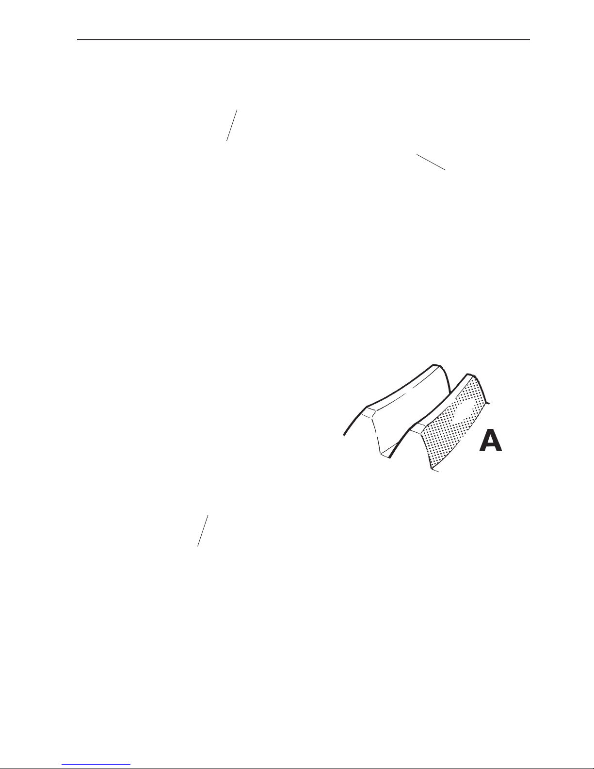
103. Check whether the marking pattern corresponds
with marking pattern A, which is correct. The pattern
should be located at the centre of the tooth, in height,
but displaced towards the small end.
NOTE! Consideration can not be given to the marking
pattern on the input pinion, since this is influenced by
both gear wheels.
884738
9999683
9999683
Page 48
46
Repair - MS2 reverse gear and upper gear housing, sailboat drive
Final assembly
107. Put a needle roller bearing (1) on the vertical
shaft.
Then put on the measured spacer washer (2), the
three domed small washers (3), the large domed
washer (4) and the lock washer (5).
104. If the marking pattern resembles B, the shim
thickness in the input bearing housing should be reduced. If the gear flank clearance becomes too small,
the gear wheels must be disassembled.
Remove the shims from the gear wheels to the same
extent, and re-install the gear wheels.
Apply marking dye to the gears again, turn them round
and check the contact patches.
105. If the marking pattern is similar to C, move the
input gear housing and gear wheel in the opposite directions to what was specified in item 104.
When the correct flank clearance and marking pattern
have been obtained, the input gear housing and upper
gear housing should be disassembled, and all marking
dye washed off.
NOTE! Keep the reverse gear upside down when the
lower gear wheel is washed clean, to prevent the dye
from finding its way into the bearing.
106. Measure distance (A) between the bearing and
gear wheel hub. This distance should be between 3.4
and 3.8 mm (0.13 and 0.15").
If the distance is 4.10 mm (0.161"), for example, a
spacer washer must be inserted.
If the distance exceeds 4.20 mm (0.165"), two spacer
washers must be inserted.
A
5
4
3
2
1
5
4
3
2
1
Page 49

47
Repair - MS2 reverse gear and upper gear housing, sailboat drive
108. Put the shaft in a press.
Use tool no. 884725 and press the lock washer down
so far that the retaining ring halves can be put into the
groove.
109. Reverse gear MS2
Put the shaft in the housing. Put the calculated thickness of shims on, followed by the outer bearing race.
Press the outer bearing race on with tool no. 884732.
110. Align the “TOP” marking upwards, and install
sliding sleeve (1) and needle roller bearing (2).
111. Put a new O-ring in the groove in the upper bearing housing. Then install the bearing housing on the
housing.
1
2
TOP
884725
884732
Page 50

48
Repair - MS2 reverse gear and upper gear housing, sailboat drive
115. Put the plain bearing (1) on the shaft and install
the slipping clutch.
112. Measure the distance between the gear wheel
and the bearing.
Also refer to item 106.
113. Put on, from the left, the measured spacer washer, three small domed washers, a large domed washer
and the lock washer.
114. Press down the large washer so far that the retaining ring halves can be put in the groove.
Use tool no. 884725.
884725
1
Page 51

49
Repair - MS2 reverse gear and upper gear housing, sailboat drive
116. Reverse gear MS2
Put a new O-ring on the cover.
Make sure that the oil drain is correctly aligned. Screw
the cover down onto the housing.
117. Reverse gear MS2
Put on a new O-ring, put the tested thickness of
shims on the output bearing housing, and then fix it to
the housing with screws.
Turn the shaft slightly, to allow the gear teeth to
mesh. Install the gear bracket with two of the screws.
118. Drive, 120S, 120S-B, -C, -D, -E
Put on a new O-ring and install the rear cover and
gear bracket on the upper gear.
Install the sea water valve. Use sealant, Volvo Penta
part no. 1141570 on the threads.
119. Put a new O-ring and the tested thickness of
shims on the input bearing housing.
NOTE! The bearing housing can only be installed in
one position, because of the hole pattern. Screw the
bearing housing down onto the housing.
Page 52

50
Repair - MS2 reverse gear and upper gear housing, sailboat drive
121. Reverse gear MS2
Install the dipstick. Fill up with oil.
Please refer to
Technical Data
for oil volume, grade
and viscosity.
Check the oil level with the dipstick and install the oil
filler cap.
125. Drive, 120S, 120S-B, -C, -D, -E
Install the dipstick and oil filler cap.
The lower gear must be installed before the oil is put
in.
Please refer to
Technical Data
for oil volume, grade
and viscosity.
120. Install the gear change mechanism in the reverse
gear housing. Please refer to items 10-13.
Page 53

51
4. Undo the four socket cap screws which retain the
pinion in the housing, and disassemble the pinion.
Save the shims between the gear housing and the pinion.
Repair of MS2V reverse gear, angle gear
This section only refers to repair of the angle gear and
its sub-components. Please refer to the MS2 information for general information about the reverse gear.
1. Clean the outside of the reverse gear. Remove the
drain plug (1) and drain the oil.
2. Undo the 4 nuts, the 2 socket cap screws and remove the angle gear from the reverse gear.
Tubular shaft,
disassembly
3. Undo the six screws which hold the tubular shaft in
the housing, and drive out the tubular shaft with a lead
hammer etc. Save the shims between the cover and
the gear housing.
1
Page 54

52
Repair of MS2V reverse gear, angle gear
5. Remove the seal ring.
NOTE! The seal ring must always be replaced by a
new one.
6. Press the bearing race out of the housing. Use tool
no. 884856 and shaft 884859. Save the shims beneath the bearing race.
7. Screw two screws into the tubular shaft and fix it by
putting the two screw heads in a vise. Undo the tubular nut with a hook wrench. When the tubular nut is removed, remove the outer ball bearing as well. Please
refer to item 8.
8. A claw extractor must be used to free the bearing
fully from the tubular shaft. Grip round the tubular nut.
884859
884856
Page 55

53
Repair of MS2V reverse gear, angle gear
9. Put the tubular shaft in sleeve 884637 and press
out the tubular shaft, which also removes the crown
wheel and the inner roller bearing.
10. Remove the seal ring from the cover. The seal
ring must always be replaced by a new one.
11. Remove the bearing race from the cover. Use tool
no. 884857 and shaft 884859.
884637
884859
884857
Page 56

54
Repair of MS2V reverse gear, angle gear
Pinion,
disassembly
12. Fix the pinion in a vise and undo the two nuts with
a hook wrench.
13. Put the pinion in sleeve 884723 and press out the
pinion, which also removes upper roller bearing.
14. Remove the roller bearing from the pinion, using a
knife extractor and press.
15. Remove the two bearing races in the pinion housing with tool no. 884720.
16. Remove the needle roller bearing in the pinion nut
with mandrel 884859.
884720
884723
884859
Page 57

55
Repair of MS2V reverse gear, angle gear
18. Install the inner roller bearing on the pinion, use
the two sleeves 884732 and 884836 .
19. Place the pinion in the housing (turn the housing
so that the recessed holes for the socket cap screws
are on top). Press the other roller bearing on, using
tool no. 884732.
NOTE! Do not press the bearing until it bottoms.
Some clearance must be left. When the nut is tightened, the bearing housing is pressed together and the
clearance disappears.
20. Apply thread locking fluid, Volvo Penta part no.
1161053-2 on the threads of the nut and install it with
the chamfered side upwards.
Start off with low torque and check the preload with a
spring balance 9985494 and a piece of string wrapped
round the bearing housing.
Pre-load: 10,0-17,5 N (2.25-3.93 lbf).
Pinion,
assembly
17. Install the bearing races in the pinion housing with
tool 884834 and shaft 884859.
884859
884834
884732
884836
884732
9985494
2.25-3.93 lbf
Page 58

56
Repair of MS2V reverse gear, angle gear
21. Install a new needle roller bearing in the pinion nut,
using mandrel 884859.
Apply thread locking fluid, Volvo Penta part no.
1161053-2, on the threads and install the nut.
Tightening torque: 140 Nm (103.26 lbf ft)
884859
Bearing and tubular shaft,
assembly
22. Apply sealant, Volvo Penta part no. 1161099-5 to
the gearbox housing and install a new seal ring. Use
tool no. 884834 and shaft 884859.
Wipe some grease, Volvo Penta part no. 828250-1 on
the lip of the seal ring.
23. Put shims with a total thickness of 0.70 mm in the
housing and install the bearing race with tool 884834
and shaft 884859.
884859
884834
Page 59

57
Repair of MS2V reverse gear, angle gear
24. Apply sealant, Volvo Penta part no. 1161099-5 to
the cover and install a new seal ring. Use tool no.
884834 and shaft 884859. Wipe some grease, Volvo
Penta part no. 828250-1 on the lip of the seal ring.
25. Install the bearing race in the cover with tool
884855 and shaft 884859.
26. Put the cover in the tubular shaft and press the
roller bearing on with sleeve no. 884833. Press the
bearing all the way down to the step on the shaft.
27. Press the crown wheel on with sleeve no. 884833.
884833
884833
884859
884855
884859
884834
Page 60

58
Repair of MS2V reverse gear, angle gear
28. Screw two screws into the tubular shaft and fix it
in a vise. Align the tubular nut with the un-threaded
section towards the crown wheel and install it with tool
no. 884860.
Tightening torque: 140 Nm (103.26 lbf ft)
884860
29. Press the outer roller bearing on. Use sleeve
884835.
884835
30. Put shims with a total thickness of 0.70 mm be-
tween the cover and the housing.
Install the tubular shaft in the housing and fix it with
two diagonally opposed screws.
Tightening torque: 25 Nm (18.44 lbf ft)
Check the pre-load with a spring balance, 9985494
and a piece of string wound round the tubular shaft.
Pre-load: 10-16 N (2.25-3.60 lbf)
Too low pre-load: Increase the shim thickness under
the upper cover.
Too high pre-load: Reduce the shim thickness under
the upper cover.
Check the pre-load again and continue until the correct pre-load has been obtained.
9985494
2.25-3.60 lbf
Page 61
59
Repair of MS2V reverse gear, angle gear
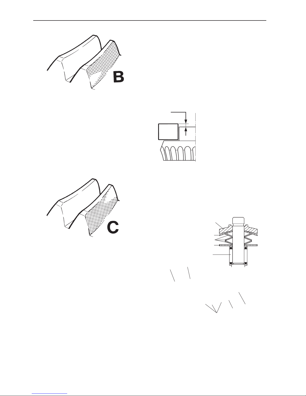
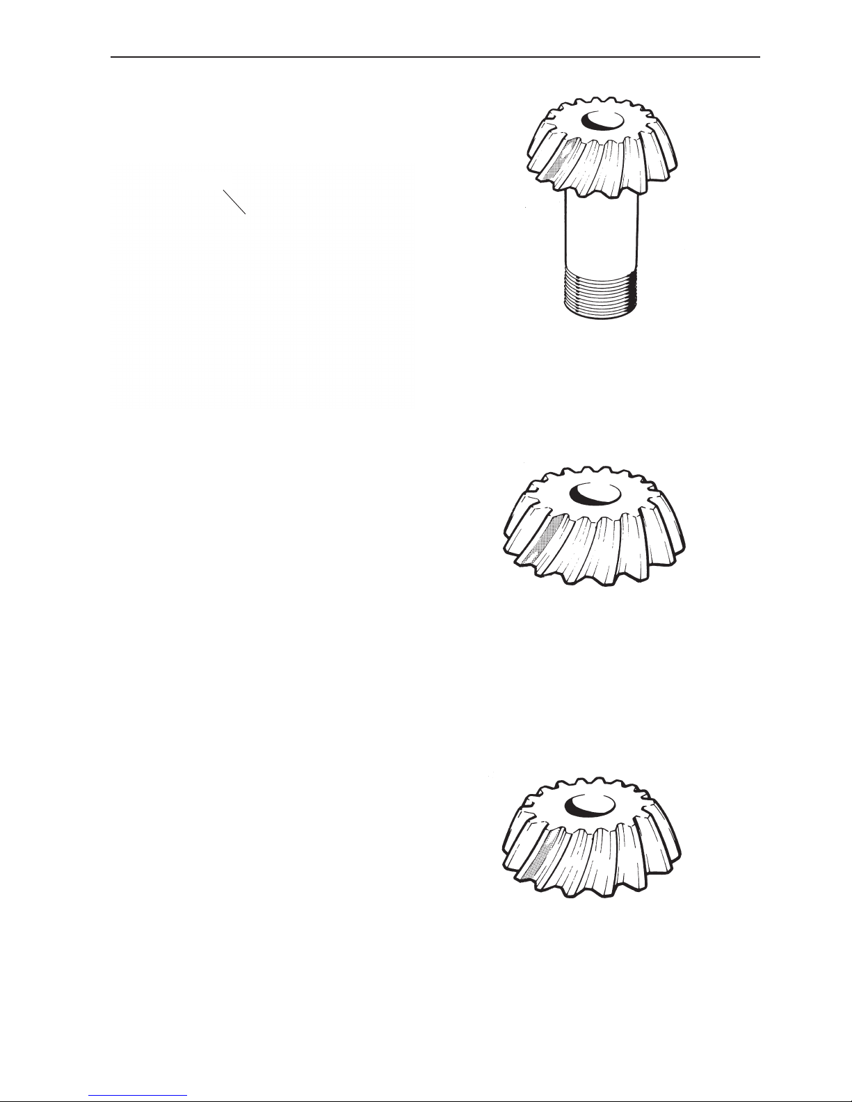
33. Remove the pinion and check whether the marking
pattern on the pinion corresponds with illustration A,
which is correct.
The pattern should be located at the centre of the
tooth, in height, but displaced towards the narrower
end.
34. If the marking pattern is similar to B, move the
crown wheel down.
NOTE! To retain the pre-load on the tubular shaft, the
thickness of shims between the cover and the gearbox housing must be reduced to the same extent.
If the flank clearance is too small after this operation,
move the pinion upwards by increasing the thickness
of the shims between the gearbox housing and the
pinion.
35. If the marking pattern is similar to C, move the
crown wheel and pinion in the opposite directions to
what was specified in the previous item.
When the correct flank clearance and marking pattern
has been obtained, wash off all marker dye from the
crown wheel and pinion.
B
C
A
31. Install the pinion in the gearbox housing, without
an O-ring and with a total shim thickness of 0.35 mm
between the pinion and the gearbox housing.
Install two of the socket cap screws, diagonally opposed. Torque to 9 Nm (6.64 lbf ft).
Check the flank clearance on the nut, as in the illustration. Use dial gauge 9999701 and a stand.
Flank clearance: 0.10-0.25 mm (0.004-0.010")
Adjust the flank clearance if necessary, by adding or
removing shims from between the pinion and the gearbox housing.
32. Remove the pinion and apply a thin layer of marker dye to the crown wheel and pinion.
Install the pinion again and turn it round in both directions. Brake the tubular shaft at the same time.
9999701
Flank clearance,
checking
Page 62

60
Repair of MS2V reverse gear, angle gear
36. Install the pinion in the gearbox housing together
with a new O-ring.
Tightening torque: 9 Nm (6.64 lbf ft)
Angle drive,
final assembly
37. Install the tubular shaft in the gearbox housing to-
gether with a new O-ring.
Tightening torque: 25 Nm (18.44 lbf ft)
Install a new seal ring on the tubular shaft.
38. Assemble the angle drive and reverse gear.
Use a new O-ring.
Tightening torque: 28 Nm (20.65 lbf ft).
Page 63

61
Repair - lower gear housing, sailboat drive
Repair - lower gear housing,
sailboat drive
1. Clean the outside of the drive. Remove the propel-
ler and remove the fishing line cutter. Unscrew the
drain plug and drain off the oil.
2. Remove the locking wire from the four socket cap
screws below the division line of the drive, two on
each side. Throw the wire away.
Then remove all the (10) screws.
3. Separate the upper and lower gear housings. Remove and scrap the gasket at the division line.
Remove the shims. Note the number of shims.
Remove the spacer ring (1). Tap the shaft lightly with
a plastic-faced hammer.
4. Fix fixture 884753 in a vise. Install the lower gear
housing in the fixture, so that the four pins fit the cutouts in the shaft nut. Fix the gear housing with four of
the socket cap screws.
Install tool 884264 or 884830 on the shaft. Use a
17 mm socket and undo the nut by turning the shaft
clockwise.
NOTE! Only turn enough to make the nut just come
into contact with the fixture.
Remove the fixture from the lower gear and screw the
nut off the shaft.
884264
884830
884753
1
Disassembly of the drive
Page 64

62
Repair - lower gear housing, sailboat drive
5. Remove the zinc ring.
3858852
884264
884830
6. Remove the two socket cap screws in the bearing
housing.
7. Remove the propeller shaft and bearing housing.
Use slide hammer 884161 and extractor 884611.
8. Lock the pinion nut with tool no. 3858852. Press
the shaft down and make sure that the pinion nut engages in the tool. Fix the tool to the rear bearing housing, using socket cap screws.
9. Install tool 884264 or 884830 on the vertical shaft.
Unscrew the pinion nut.
Remove the pinion. If the pinion has got stuck, it will
come loose when the shaft is pressed out later on, in
item 11.
884161
884611
Page 65

63
Repair - lower gear housing, sailboat drive
11. Install tool no. 884743 in the lower gear housing.
Use a 5/16" x 20 mm (3/4") screw. Alternatively, one
of the drive fixing screws can be used together with a
5 mm thick washer.
Take out the loose needles (25 pcs) if the needle roller
bearing needs to be changed.
Tighten the screw with the steel ball so that it presses
the vertical shaft up. Wrench size 24 mm. Then disassemble the tool.
12. Disassemble the outer bearing race from the upper
part of the gear housing, using tool no. 884761 in
combination with tool no. 884721.
13. Remove the bearing race with expander 884750
and shaft 884143.
The expander is inserted from underneath, and the
shaft from above.
884743
884750
884143
884761
884721
884761
10. Disassemble the bearing race with tool no.
884761.
NOTE! Note the number of shims between the bearing
race and the gear.
Page 66

64
Repair - lower gear housing, sailboat drive
Vertical shaft,
disassembly
14. Remove the roller bearings with a knife extractor
as counterhold. Use a hydraulic press together with a
suitable mandrel.
15. Remove the ferrule (1). Use a knife puller as a
counterhold.
NOTE! The ferrule must always be changed when the
shaft has been removed or when the pinion has been
changed.
16. The ground needle roller bearing race on the vertical shaft should not be changed. If the roller bearing is
damaged, the entire shaft must be changed.
Then clean all components. Change worn or damaged
components.
Vertical shaft,
assembly
NOTE! Oil all components before or during assembly.
17. Put a new ferrule (1) on the vertical shaft.
18. Install a new roller bearing with mandrel 884755.
NOTE! Press until the bearing touches the ferrule.
19. Install the other roller bearing inverted, i.e. with the
smaller end upwards. Use mandrel 884755.
NOTE! Press so far that the bearings touch each oth-
er.
1
1
1
884755
884755
Page 67

65
Repair - lower gear housing, sailboat drive
Propeller shaft,
disassembly of bearings and
drive
20. Remove the front roller bearing.
Use a knife extractor as a counterhold and press the
bearing out with a hydraulic press and a suitable mandrel.
21. Remove the rear roller bearing. Use a knife extractor as a counterhold, with a 17 mm socket on the
shaft end.
NOTE! If the gear wheel is going to be changed as
well, the bearing can be pressed off at the same time.
Please refer to item 22.
22. Remove the gear wheel with tool no. 884753. Use
a socket to protect the end of the shaft.
NOTE! The gear wheel and pinion are classed together and can only be changed as a complete unit.
Rear bearing housing,
disassembly
23. When the seal rings are changed, the outer bear-
ing race should also be changed.
Put the bearing housing on tool no. 884723. Press out
the seal rings with tool 884752 and shaft 9991801.
Press the outer bearing race out at the same time as
the housing.
NOTE! Note the number of shims. Save the shims.
884753
884723
884752
9991801
Page 68

66
Repair - lower gear housing, sailboat drive
Propeller shaft, assembly of
bearings and drive
24. Press the gear wheel down to the step on the pro-
peller shaft with tool no. 884753. Make sure that it
seats securely.
25. Install the front roller bearing with tool no. 884754.
Propeller shaft, shimming
26. For when only new bearings have been installed.
Use the previously installed shims in the first instance. In other cases, the shim thickness can be
calculated as in items 27–29.
27. Put the outer bearing race on the front ball bearing. Press it hard against the bearing and measure
distance (X) with a caliper gauge, between the rear
plane of the gear wheel and the outer front plane of
the bearing race.
In this case, the distance is 100.20 mm.
28. Dimension (T) is stamped on the starboard side of
the gear housing division to permit the shim thickness
under the front bearing race to be calculated, which is
17 in this case. The dimension of the division plane
can vary between 0 and 30.
884753
X
884754
T
Page 69

67
Repair - lower gear housing, sailboat drive
29. The illustration shows the K dimension (– 5) en-
graved on the gear wheel. The other engraved figure
(7) shows the pinion which the gear wheel belongs together with. The pinion should have the same figure
engraved on it.
Example:
T = Stamped dimension on the division plane (17)
K = Engraved dimension on the gear wheel (–5)
X = Dimension measured with caliper gauge (100,20)
101 = Constant
Shim thickness = 101 + (T + K) – X
100
Shim thickness = 101 + (0,17 + – 0,05) – 100,20
Shim thickness = 101 + 0,12 – 100,20
Shim thickness = 0,92 mm
30. Put shims of the correct thickness in the lower
gear housing. Add a further 0.05 – 0.10 mm. In this
case, we put a total of 1.00 mm shims in the housing.
Shims are available in the following standard thicknesses: 0.10 mm, 0.15 mm, 0.35 mm, 0.50 mm.
884754
31. Install the outer bearing race in the gear housing
with mandrel 884756. Use the rear bearing housing as
a guide.
32. Press the rear roller bearing down onto the propeller shaft. Use mandrel 884754.
K
884756
Page 70

68
Repair - lower gear housing, sailboat drive
Rear bearing housing,
shimming
For when only new bearings have been installed. Use
the previously installed shims in the first instance.
When the gear housing or rear bearing housing is
changed, the shim thickness should be calculated as
below.
33. Shimming, alternative 1
Put the propeller shaft in the gear housing. Install the
outer bearing race for the propeller shaft roller bearing.
Press the bearing race hard and turn the shaft round,
to take up any play in the bearing.
Then use a depth micrometer 9985472 to measure the
distance between the rear plane of the gear housing
and the rear outer bearing race for the propeller shaft.
We call this dimension Y.
34. Shimming, alternative 2
Alternatively, we can add shims until the outer bearing
race is flush with the gear housing. Clean off all traces
of sealant from the mating surface of the gear housing
against the bearing housing.
IMPORTANT! Make sure that the surface is not
damaged. Do not use steel tools.
Use a steel rule or caliper gauge to check.
35. There is a dimension (B) punched on the rear
bearing housing. This dimension is stamped underneath the bearing housing, and varies between 50-70.
In this case, the distance is 65 mm.
Example: Y is measured to 1.05 mm in this case.
Shim thickness = Y – B
100
Shim thickness = 1,05 _ 65
100
Shim thickness = 1,05 – 0,65 = 0,40
Shim thickness = 0,40 mm
Shims are available in the following standard thicknesses: 0.10 mm, 0.15 mm, 0.35 mm, 0.50 mm.
Use shim thickness 0.35 + 0.10 = 0.45 mm.
B
9985472
Page 71

69
Repair - lower gear housing, sailboat drive
Rear bearing housing,
assembly
36. Install a new seal ring in the bearing housing, us-
ing tool no. 884752 and shaft 9991801. Apply sealant,
Volvo Penta part no. 1161099-5, to the mating face
between the seal and the bearing housing.
NOTE! Align the open side of the seal ring backwards
(aft).
37. Install the other seal ring by using the same tool.
NOTE! Align the open side of the seal ring forwards
(towards the bow). When the seal rings have been installed, the spring in the rings should face away from
each other.
38. Apply some grease to the seal rings, Volvo Penta
part no. 828250-1.
39. Put shims of the correct thickness in the bearing
housing. In this case, they are 0.45 mm.
40. Assemble the outer bearing race with tool no.
884756.
Oil and install new O-rings, 2 pcs.
41. Install the propeller shaft in the gear housing.
NOTE! Turn the shaft carefully, to avoid damaging the
sealing lips on the seal rings.
Tightening torque: 30 Nm (22.13 lbf ft).
Check the preload. Please refer to item 42.
During final assembly:
Apply sealant, Volvo Penta part no. 1161231-4, to the
mating face between the bearing housing and the
drive.
Apply thread locking fluid, Volvo Penta part no.
1161231-4, to the screws and install the bearing housing on the drive.
9991801
884752
884756
Page 72

70
Repair - lower gear housing, sailboat drive
Pre-load
42. Check that there is no slack in the propeller shaft
Check the preload in the shaft.
Method 1. Wind a piece of string round the shaft and
pull with spring scale 9985494. Please refer to the figure above.
Permissible preload: 0 (no slack) – 35 N (0–7.87 lbf).
Method 2. Install the propeller nut on the shaft. Turn
the shaft with a torque wrench. Turn at an even
speed, about 1 revolution/sec.
Permissible preload: 0.5 ± 0.3 Nm (0.37 ± 0.22 lbf ft).
When there is slack in the shaft, or the pre-load is incorrect, change the thickness of the shims underneath the bearing race in the rear bearing housing.
If preload is correct: Disassemble the bearing housing and remove the propeller shaft.
Vertical shaft
44. Install a new needle roller bearing. Use tool no.
884746.
The tool consists of three sections. Please refer to
the
Special Tools
section.
NOTE! The needle roller bearing has loose rollers. For
this reason, the new bearing has a transport shield.
Press bearing retainer 884747 into the needle roller
bearing. The transport shield (foam rubber) is then
pressed out. Insert the screw with flange 884748 from
above and the bearing retainer with needle roller bearing from below. Turn the screw round until the needle
roller bearing is in place. Use a wrench on the bearing
holder to keep it in place. Then disassemble the tool.
45. Install the vertical shaft in the housing. Be careful
to ensure that the needle rollers do not fall out. Then
install the pinion. Apply thread locking fluid, Volvo
Penta part no. 1161075-5, on the threads and install
the nut.
NOTE! One side of the nut has a chamfer which
should face the pinion.
43. Install the lower one of the two bearing races. Use
mandrel 884757.
884747
884748
9985494
884757
Page 73

71
Repair - lower gear housing, sailboat drive
46. Lock the pinion nut with tool 3858852. Press the
shaft down and make sure that the pinion nut engages
in the tool. Fix the tool to the rear bearing housing, using socket cap screws.
Install tool 884264 or 884830 on the vertical shaft.
Tighten the pinion nut.
Wrench size: 17 mm.
Tightening torque: 110 ± 10 Nm (81.13 ± 7.38 lbf ft).
47. Install the bearing housing on the propeller shaft.
NOTE! Turn the shaft carefully, to avoid damaging the
sealing lips on the seal rings.
Apply sealant, Volvo Penta part no. 1161231-4, to the
mating face between the bearing housing and the
drive.
Then install the propeller shaft and bearing housing on
the gear housing.
Apply thread locking fluid, Volvo Penta part no.
1161231-4, to the screws.
Tightening torque: 30 Nm (22.13 lbf ft).
48. Install the upper nut on the vertical shaft.
NOTE! The chamfered side of the nut must face
downwards.
884753
49. Then screw tool 884753 to the division plane, so
that the “teeth” engage on the nut. Fix the tool, with
the lower gear housing, in a vice.
NOTE! First tighten the nut by hand, so that the tool
lies flush against the division plane.
884264
884830
3858852
Page 74

72
Repair - lower gear housing, sailboat drive
Flank clearance
50. Install tool 884264 or 884830 on the vertical shaft.
Turn the shaft clockwise with a heavy wrench or
torque wrench. Wrench size: 17 mm.
NOTE! The nut must be tightened so hard that the ferrule is deformed. The torque needed is about
230–250 Nm (169.64–184.40 lbf ft).
The flank clearance is zero (0) before the nut begins
to nip up.
51. When the highest torque specified above has been
reached, the gear housing should be removed from
the vice and fixed vertically instead. Let the tool remain on the gear housing.
Install dial gauge 9999683 on the propeller shaft
splines. Tap the vertical shaft from above, so that it
comes as far down as possible. Turn the propeller
shaft forwards and backwards.
Flank clearance: 0.04-0.10 mm (0.002-0.004")
If the clearance is too small, the nut must be tightened a further turn. 1/4 turn is about 0.02–0.03 mm
(0.0008–0.0012") .
IMPORTANT! Only tighten a small amount at a
time, and check the clearance each time.
If the flank clearance becomes too large, the vertical
shaft must be disassembled and the ferrule changed,
since it can only be used once.
9999683
Page 75
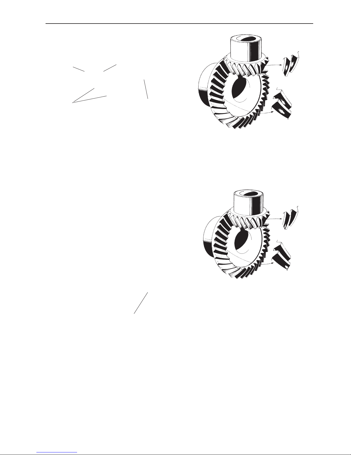
73
Repair - lower gear housing, sailboat drive
Marking pattern
52. When the correct gear flank clearance has been
obtained, remove tool 884753 from the lower gear.
Then turn the tool so that the “teeth” (A) face outwards. Fix the tool with two screws to the lower gear
housing.
Press the vertical shaft in with tool no. 884766 which
is screwed to the other tool. Leave tool 884264 or
884830 in place.
Then disassemble the propeller shaft and apply marker dye to the gear wheels.
53. Install the propeller shaft again and turn it round in
both directions.
Brake the propeller shaft strongly.
NOTE! Press the vertical shaft in with tool no. 884766
at the same time as it is turned round.
54. Disassemble the propeller shaft and check that
the marking pattern on the gear teeth corresponds
with the marking pattern in the illustration above or the
figures in items 55 and 56.
55. If the marking pattern is displaced in relation to
the figure above, the thickness of the shims underneath the front bearing race must be reduced and the
thickness of the shims behind the bearing race in the
rear bearing housing must be increased to the same
extent. It is important that the preload is not changed.
NOTE! In this case, the propeller shaft is displaced
forwards (towards the pinion), which reduces flank
clearance. For this reason, it is necessary to install
tool no. 884753 and tighten the upper nut a bit more
until correct flank clearance has been obtained.
Please refer to items 50 and 51. Then check the contact patch again, as in items 52-54.
884766
884753
884766
A
884264
884830
Page 76
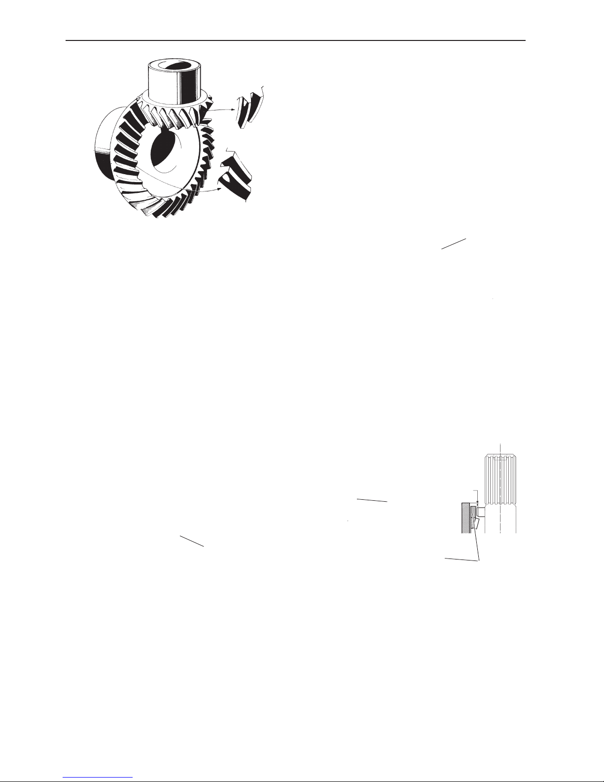
74
Repair - lower gear housing, sailboat drive
Model 120S
Installation, lower gear
housing–adapter housing
Preferably use the shims which were installed previously, if only new bearings have been installed. Shim
thickness can also be measured as in the points below.
58. Check that there is no end float in the vertical
shaft. Then install spacer ring (1).
59. Use a depth micrometer 9985472 to measure the
distance (A) from the division plane down to the spacer ring (1).
1
56. On the other hand, if the marking pattern is dis-
placed in relation to the figure above, the thickness of
the shims underneath the front bearing race must be
increased and the thickness of the shims behind the
bearing race in the rear bearing housing must be reduced to the same extent.
NOTE! In this case, the propeller shaft will be displaced backwards (away from the pinion), which
means that the flank clearance will be too large. This
can not be changed in any other way than by removing the vertical shaft, pressing off the roller bearings
and changing the ferrule.
Install a new ferrule. Then re-install the bearings and
put the shaft back in the gear housing. Turn round to
establish the new flank clearance and check the
marking pattern. Please refer to items 50-51.
57. When the correct flank clearance has been obtained, disassemble the tool and propeller shaft, and
wash off all marker dye from the crown wheel and pinion.
Re-install the propeller shaft and rear bearing housing.
Please refer to item 47. Then install the upper, outer
bearing race. Use tool no. 884757.
884757
1
A
9985472
Page 77
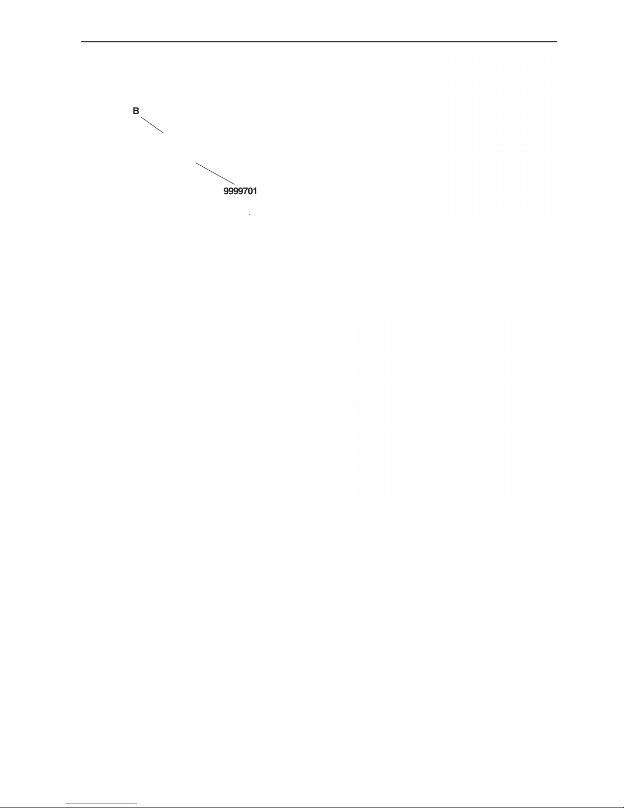
75
Repair - lower gear housing, sailboat drive
60. Measure the thickness of gasket (B) with micrometer 9999701.
61. Measure the height of flange (C) on the adapter
housing.
Example:
a) When distance (A) is measured, we obtain a dis-
tance of 5.70 mm in this case.
b) Gasket (B) thickness is measured as 0.30 mm.
c) Flange height (C) is measured as 3.85 mm.
A + B – C = shim thickness
5.70 + 0.30 – 3.85 = 2.15
Shim thickness = 2.15 mm
9999701
B
62. Install the calculated thickness of shims and gas-
ket on the division plane of the lower gear housing.
NOTE! The text on the gasket must face upwards.
The hole pattern in the gasket only fits one way round.
63. Install the adapter housing with rubber sleeve on
the lower gearing housing. Apply MoS2 based grease,
Volvo Penta part no. 1161029-2 to the socket cap
screws. Put washers on the six socket cap screws
and use a torque wrench to tighten them.
Tightening torque: 30 Nm (22.13 lbf ft).
NOTE! Torque the screws diagonally, then re-check
their tightening.
Install the cooling water tap on the port side. Apply
sealant, Volvo Penta part no. 1141570-0 on the
threads.
NOTE! Check that the adapter flange has entered the
gear housing and presses the shims down, so that
there is no end float in the vertical shaft. Also check
the flank clearance.
Page 78
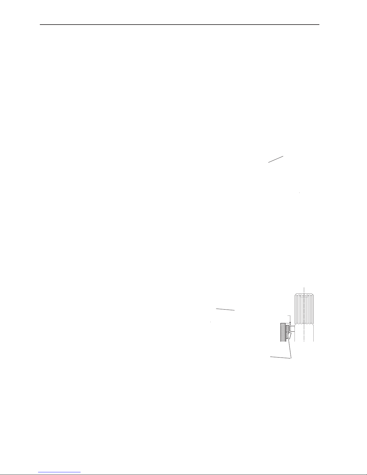
76
Repair - lower gear housing, sailboat drive
Models 120S-B, -C, -D, -E
Installation, lower gear
housing–adapter plate.
Preferably use the shims which were installed previously, if only new bearings have been installed. Shim
thickness can also be measured as in the points below.
66. Check that there is no end float in the vertical
shaft. Then install spacer ring (1).
67. Use a depth micrometer 9985472 to measure the
distance (A) from the division plane down to the spacer ring (1).
1
64. Install the adapter section on the upper housing.
Torque the socket cap screws alternately.
Tightening torque: 40 Nm (29.50 lbf ft).
Only tighten bracket (1) by hand.
65. Put a new O-ring on the adapter section neck.
Check that the slipping clutch is in place in the upper
gear housing and then fit the housings together.
NOTE! Put washers under the screw heads.
Tightening torque: 30 Nm (22.13 lbf ft).
Secure the four screws with locking wire. Tighten the
four nuts.
Tightening torque: 23 Nm (16.96 lbf ft).
Tighten the two screws on the front bracket.
Tightening torque: 40 Nm (29.50 lbf ft).
1
A
9985472
Page 79
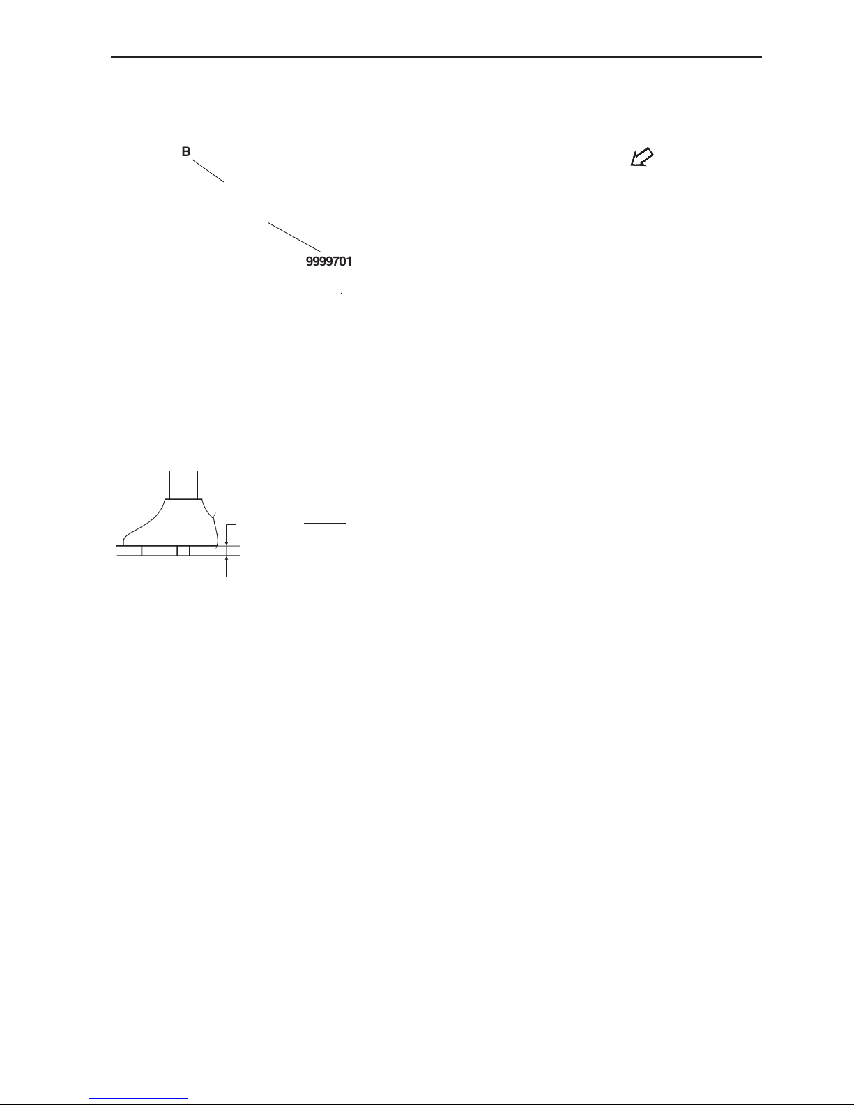
77
Repair - lower gear housing, sailboat drive
68. Measure the thickness of gasket (B) with micrometer 9999701.
69. Measure flange (C) on the adapter plate with micrometer 9985472.
Example:
a) When (A) is measured, we obtain a distance of
5.70 mm in this case.
b) Gasket (B) thickness is measured as 0.30 mm.
c) Flange height (C) is measured as 3.85 mm.
A + B – C = shim thickness
5.70 + 0.30 – 3.85 = 2.15
Shim thickness = 2.15 mm
70. Install the calculated thickness of shims and gasket on the division plane of the lower gear housing.
NOTE! The text on the gasket must face upwards.
The hole pattern in the gasket only fits one way round.
71. Put the rubber sleeve on the upper gear housing.
Install the cooling water tap. Apply sealant, Volvo
Penta part no. 1141570-0 on the threads.
9999701
B
9985472
C
Page 80
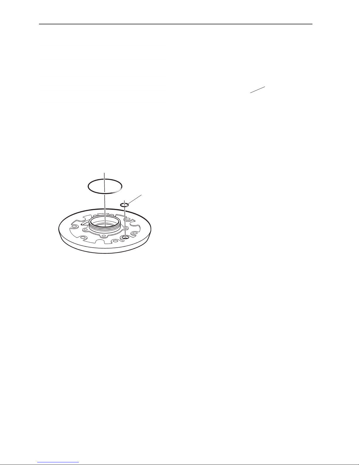
78
Repair - lower gear housing, sailboat drive
Oil and install a new O-ring (1) in the cutout in the
adapter plate.
74. Fit the gear housings together. Apply MoS2 based
grease, Volvo Penta part no. 1161029-2 to the socket
cap screws. Install the screws, 10 pcs. The two long
screws should be located by the rear edge.
Put washers under the screw heads and distribute the
screws with holes in the screw heads so that there are
two on each side.
Tightening torque: 30 Nm (22.13 lbf ft).
73. Install the adapter plate on the upper gear housing. Apply MoS2 based grease, Volvo Penta part no.
1161029-2 to the three socket cap screws. Put washers on the socket cap screws and use a torque
wrench to tighten them. Torque the screws alternately.
Tightening torque: 30 Nm (22.13 lbf ft).
Install the slipping clutch (1).
72. Oil and install a new O-ring on the adapter section
neck.
Reverse installed drive (180°)
1
1
Page 81

79
Repair - lower gear housing, sailboat drive
75. Secure four of the screws, the ones with holes in
their heads, with locking wire, two screws on each
side as in the illustration.
Other components,
installation
76. Install a new zinc ring.
Tightening torque: 12 Nm (8.85 lbf ft)
77. Change the gasket on the oil drain plug.
IMPORTANT! The gasket must be allowed soak
in oil for about 15 minutes before assembly.
Leakage would otherwise occur.
Pressure test the drive, please refer to the
Pressure
Testing
section.
Fill up with engine oil.
Please refer to
Technical Data
for oil volume, grade
and viscosity.
Check the oil level with the dipstick and install the oil
filler cap.
IMPORTANT! When the drive is installed on the
engine the screws must be dipped in oil (including the heads) and torqued.
Tightening torque: 20 Nm (14.75 lbf ft), alternately,
diagonally. Also do an extra
check of tightening.
Page 82
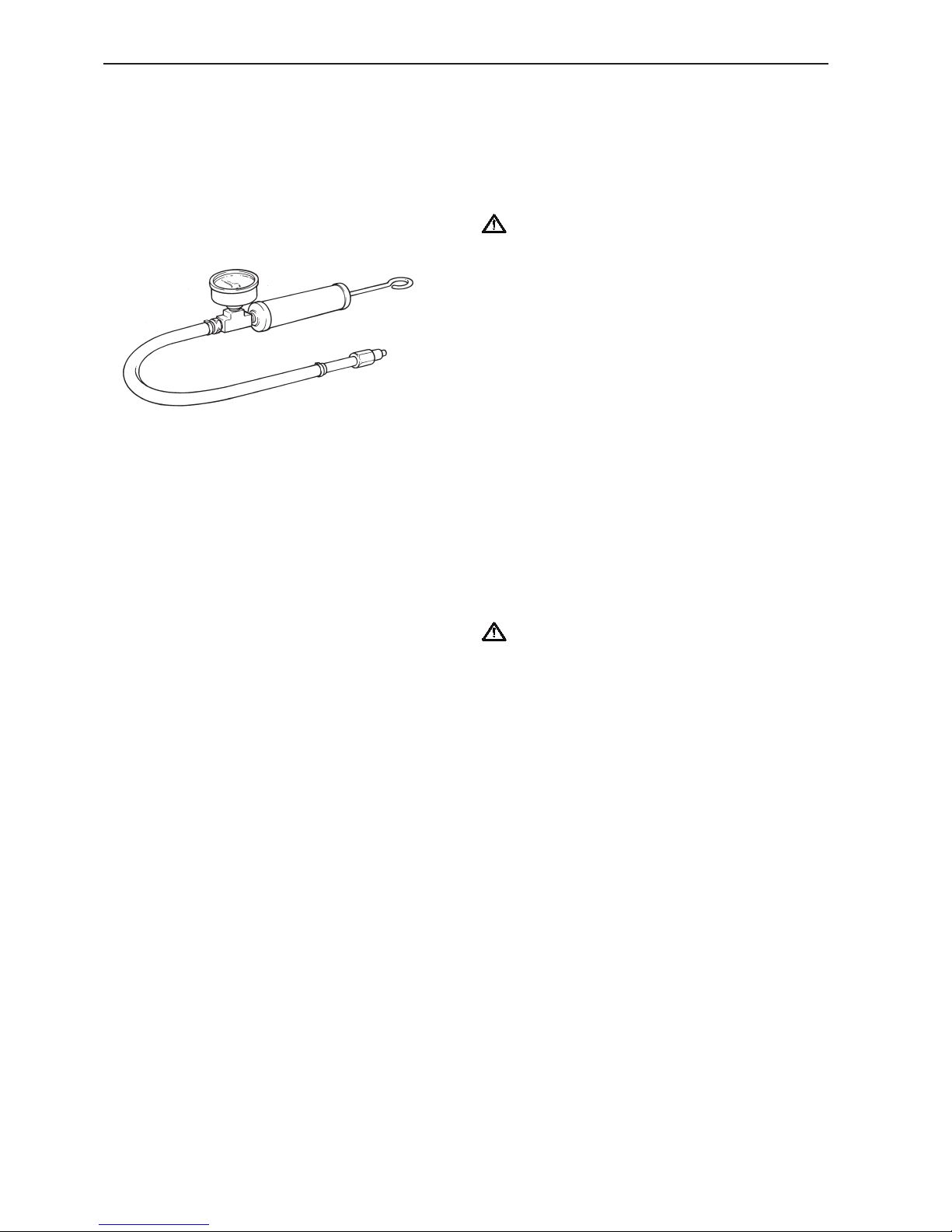
80
Repair - lower gear housing, sailboat drive
Painting of the drive
Most countries have legislation which regulates the
use of growth inhibiting paints. In some cases, their
use is completely banned on pleasure boats. Ask your
Volvo Penta Dealer for advice on alternative methods
in this case.
IMPORTANT! Find out about current legislation
for painting with growth inhibiting paints / antifouling paints.
The drive
The top coat is part of the corrosion protection of the
drive, and it is important that any paint damage is repaired.
Sand metal surfaces lightly with 120 grit emery paper,
and use finer paper on painted surfaces. Wash with
cellulose thinners or an equivalent product. Pores
must be filled and sanded.
Paint with Volvo Penta original primer plus a top coat.
Give the paints time to harden.
The drive should be coated with Volvo Penta anti-fouling paint to prevent the growth of weed and barnacles.
Apply in accordance with the directions on the package.
IMPORTANT! The protective anodes on the
drive and propeller must not be painted over.
Pressure testing
When the drive has been removed, it must be pressure tested to check for any leakage. Use special tool
3810152, which consists of a pressure gauge with
union, and a hand pump.
78. Connect the pressure gauge to the oil drain hole.
Pump the pressure up to a level not exceeding
78 kPa (11.31 psi).
Check that the pressure remains constant for 1
minute.
NOTE! Make sure that no air leakage can occur via
the hand pump.
If the pressure falls, the leakage must be localized by
using soapy water which is brushed over all joints on
the outboard section.
3810152
Page 83

81
Technical data
Type designation
Drive ....................................................................... 120S, 120S-B, 120S-C, 120S-D, 120S-E
Reverse gear........................................................... MS2, MS2B-L, MS2V
Gear ratio
Drive ....................................................................... 2.2:1
Reverse gear........................................................... 2.4:1 and 3.0:1
Flank clearance
Input gear - gear wheel, measured directly on
the gear wheels ....................................................... 0.10–0.25 mm (0.004–0.010")
Output shaft - lower drive measured on the
gear wheels. Only MS2, MS2B-A, MS2B-L,
MS2A-D, MS2A-E, MS2L-D, MS2L-E ..................... 0.10–0.25 mm (0.004–0.010")
Pinion - crown wheel. Only MS2V ........................... 0.10–0.25 mm (0.004–0.010")
Propeller shaft - vertical shaft, measured on
propeller shaft splines ............................................. 0.04–0.10 mm (0.0016–0.004")
Preload, bearings:
Input shaft bearings ................................................ 10–18 N (2.25–4.05 lbf)
Output shaft bearings .............................................. 13–25 N (2.92–5.62 lbf)
Lower shaft bearings, slipping clutch ....................... 15–30 N (3.37–6.74 lbf)
Propeller shaft bearings .......................................... No slack up to 35 N (7.87 lbf), measured on propeller shaft
Pinion bearing. Only MS2BV ................................... 10.0–17.5 N (2.25–3.93 lbf)
Tubular shaft bearing Only MS2BV ......................... 10.0–16.0 N (2.25–3.60 lbf)
Lubrication system
Oil grade, MS2A-E, MS2L-E ................................... API GL5/SAE 75W/90, synthetic
Oil grade 120S-E ..................................................... API GL5/SAE 75W/90, synthetic
Oil grade, other reverse gears and drives ................ Engine oil for Service SE or CD
Viscosity, Service SE ............................................. Multigrade SAE 10W/40 *
Viscosity, Service CD ............................................. Over +10°C: SAE 20W/30 *
Viscosity, Service CD ............................................. Below +10°C: SAE10W *
Oil volume, drive. .................................................... 2.8 l (0.74 US gallon)
With 2” extension, total ....................................... 3.1 l (0.82 US gallon)
With 4” extension, total ....................................... 3.3 l (0.87 US gallon)
Oil volume, reverse gear. ........................................ 0.8 l (0.21 US gallon)
Oil volume, MS2V reverse gear .............................. 1.8 l (0.48 US gallon)
*) Or Volvo Penta oil for diesel engines, please refer to the handbook.
Page 84

82
Technical data
Tightening torque
Reverse gear MS2, MS2B-A, MS2B-L, MS2A-D,
MS2A-E, MS2L-D, MS2L-E
Lower cover .............................................................................. 23 Nm (16.96 lbf ft)
Reverse gear MS2V
Nut on pinion ............................................................................. 140 Nm (103.26 lbf ft)
Nut on tubular shaft................................................................... 140 Nm (103.26 lbf ft)
Cover for tubular shaft ............................................................... 25 Nm (18.44 lbf ft)
Adapter housing – gear housing ................................................ 9 Nm (6.64 lbf ft)
Angle drive – gear housing ........................................................ 28 Nm (20.65 lbf ft)
Reverse gear and drive
Input bearing housing ................................................................ 8 Nm (5.90 lbf ft)
Upper bearing housing ............................................................... 23 Nm (16.96 lbf ft)
Screws for gear change mechanism ......................................... 20 Nm (14.75 lbf ft)
Screw for eccentric piston, gear shift mechanism ..................... 12 Nm (8.85 lbf ft)
Rear bearing housing, reverse gear ........................................... 23 Nm (16.96 lbf ft)
Upper gear housing – adapter housing, engine .......................... 40 Nm (29.50 lbf ft)
Oil drain plug ............................................................................. 10 Nm (7.38 lbf ft)
Drive 120S, 120S-B, 120S-C, 120S-D, 120S-E
Lower nut, vertical shaft ............................................................ 160 Nm (118.00 lbf ft)
Propeller bearing housing .......................................................... 25 Nm (18.44 lbf ft)
Zinc ring.................................................................................... 12Nm (8.85 lbf ft)
Rubber pad, drive, old model ..................................................... 23 Nm (16.96 lbf ft)
Rubber mounting, 120S-E, M8 .................................................. 25 Nm (18.44 lbf ft)
Model 120S
Upper gear housing – adapter housing nut ................................. 23 Nm (16.96 lbf ft)
Lower gear housing – adapter housing ...................................... 30 Nm (22.13 lbf ft)
Upper gear housing – adapter housing- lower gear housing ...... 23 Nm (16.96 lbf ft)
Model 120S-B, 120S-C, 120S-D, 120S-E
Upper gear housing – adapter plate ........................................... 30 Nm (22.13 lbf ft)
Upper gear housing – lower gear housing .................................. 30 Nm (22.13 lbf ft)
Page 85

83
References to Service Bulletins
Group No. Date Refers to
.........................................................................................................................................................................................
.........................................................................................................................................................................................
.........................................................................................................................................................................................
.........................................................................................................................................................................................
.........................................................................................................................................................................................
.........................................................................................................................................................................................
.........................................................................................................................................................................................
.........................................................................................................................................................................................
.........................................................................................................................................................................................
.........................................................................................................................................................................................
.........................................................................................................................................................................................
.........................................................................................................................................................................................
.........................................................................................................................................................................................
.........................................................................................................................................................................................
.........................................................................................................................................................................................
.........................................................................................................................................................................................
.........................................................................................................................................................................................
.........................................................................................................................................................................................
.........................................................................................................................................................................................
.........................................................................................................................................................................................
.........................................................................................................................................................................................
.........................................................................................................................................................................................
.........................................................................................................................................................................................
.........................................................................................................................................................................................
.........................................................................................................................................................................................
.........................................................................................................................................................................................
.........................................................................................................................................................................................
.........................................................................................................................................................................................
.........................................................................................................................................................................................
.........................................................................................................................................................................................
.........................................................................................................................................................................................
.........................................................................................................................................................................................
.........................................................................................................................................................................................
.........................................................................................................................................................................................
Page 86

84
.........................................................................................................................................................................................
.........................................................................................................................................................................................
.........................................................................................................................................................................................
.........................................................................................................................................................................................
.........................................................................................................................................................................................
.........................................................................................................................................................................................
.........................................................................................................................................................................................
.........................................................................................................................................................................................
.........................................................................................................................................................................................
.........................................................................................................................................................................................
.........................................................................................................................................................................................
.........................................................................................................................................................................................
.........................................................................................................................................................................................
.........................................................................................................................................................................................
.........................................................................................................................................................................................
.........................................................................................................................................................................................
.........................................................................................................................................................................................
.........................................................................................................................................................................................
.........................................................................................................................................................................................
.........................................................................................................................................................................................
.........................................................................................................................................................................................
.........................................................................................................................................................................................
.........................................................................................................................................................................................
.........................................................................................................................................................................................
.........................................................................................................................................................................................
.........................................................................................................................................................................................
.........................................................................................................................................................................................
.........................................................................................................................................................................................
.........................................................................................................................................................................................
.........................................................................................................................................................................................
.........................................................................................................................................................................................
.........................................................................................................................................................................................
.........................................................................................................................................................................................
.........................................................................................................................................................................................
Notes
Page 87

Report form
Do you have any complaints or other comments about this manual? Please make a
copy of this page, write your comments down and send it to us. The address is at
the bottom of the page. We would prefer you to write in English or Swedish.
From: ............................................................................
......................................................................................
......................................................................................
......................................................................................
Refers to publication: .............................................................................................................................................
Publication no: ............................................................Date of issue: ....................................................................
Suggestion/Motivation:...........................................................................................................................................
..............................................................................................................................................................................
..............................................................................................................................................................................
..............................................................................................................................................................................
..............................................................................................................................................................................
..............................................................................................................................................................................
..............................................................................................................................................................................
..............................................................................................................................................................................
..............................................................................................................................................................................
Date: ............................................................
Name: ..........................................................
AB Volvo Penta
Teknisk Information
405 08 Göteborg
Page 88

7752950-1 English 01-2001
 Loading...