

Volvo Penta MD7A, MD7A/110S Instruction Book


FOREWORD
Before you start your new Volvo Penta marine engine, you are advised to read
through this instruction book carefully. It contains information relevant to the
proper operation and maintenance of your engine.
Volvo Penta has built up an extensive service organization with service shops and
specially trained personnel at your service.
Always contact your local Volvo Penta representative for advice and when in need
of service and parts.
WARRANTY CERTIFICATE
A warranty certificate is supplied with each engine. It contains the warranty
conditions for the engine and should be studied carefully.
Also included is a report card which is to be completed by the dealer or boat seller
and forwarded to Volvo Penta.
However, if our warranty is to apply, it is an absolute condition that the measures
given in the “Check and Service Scheme” are carried out and that your engine
and equipment are looked after according to the instructions in this book. When in
doubt, always get in touch with an authorized Volvo Penta dealer.
In all correspondence with your dealer and when ordering parts, always state the
type designation and serial number of the engine and reverse gear or drive (see
starboard side of engine).
Make certain that the engine’s specification coincides with what is described in
this instruction book.
AB VOLVO PENTA
Technical Publications Dept.


1
Instruments and Controls
2
General Information
3 - 4
Running Instructions
5 - 6
Starting the engine
Running instructions
Shutdown procedure
5
6
6
Technical Description
8 - 11
Checks and Service Scheme
12
Checks and Service
13 – 23
Check daily before starting
Check every 14 days
Service every 50 hours of operation
Service every 100 hours of operation
Venting the fuel system
Service when laying-up and launching
13
13 - 14
15 - 16
17 – 22
23
24 – 28
Fault Tracing Scheme
29
Technical Data
30 – 31
Wiring Diagram
32
Engine Component Guide
33 – 34
Index, alphabetical order
35
CONTENTS
2
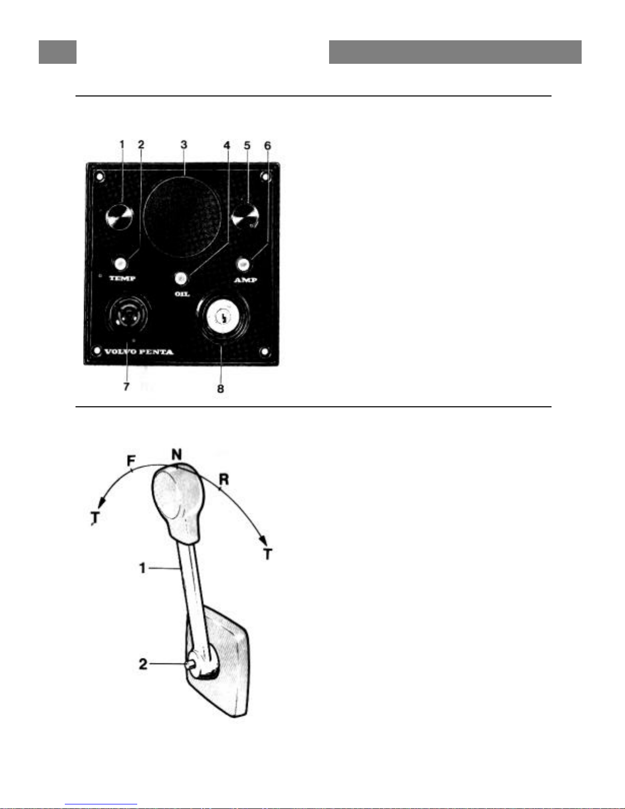
INSTRUMENT PANEL
1. Switch, extra lighting
2. Warning lamp, “high temperature”
3. Place for instrument (dia 52 mm,
opt. equipment)
4. Warning lamp, “low oil pressure”
5. Switch, extra lighting
6. Warning lamp, “No battery charging”
7. Buzzer, “low oil pressure, high temperature”
8. Key switch
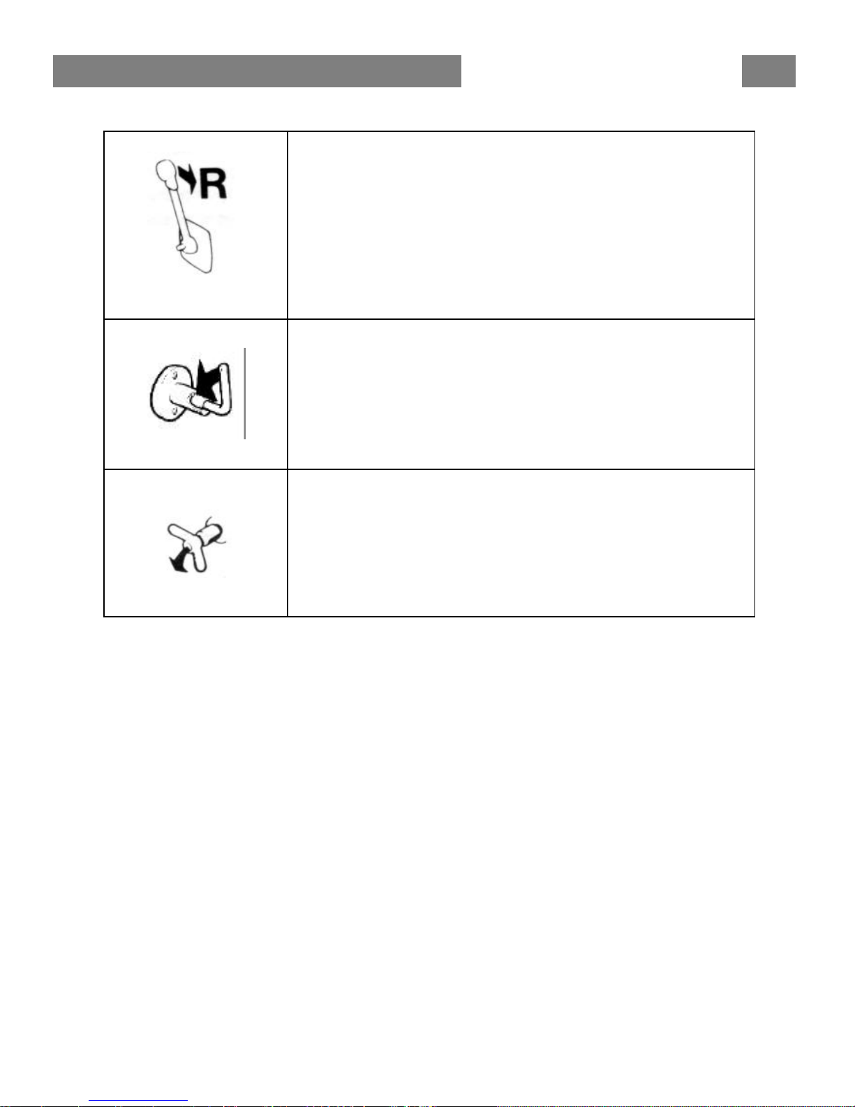
CONTROL SYSTEM
Volvo Penta Single Control System
For side mounting
1. Control lever
2. Disengaging button
Push in the button when the control lever is in neutral
and move the lever a bit forwards. Release button.
The lever is now used only for engine speed control.
To use the lev er for both engine speed control and
gear-changing, push in the button and pull back the
lever to neutral position and move it again “Forward” or
“Reverse”.
N = Neutral
F = Control lever in position for running “Forward”
R = Control lever in position for running “Reverse”
T = Engine speed control
INSTRUMENTS AND CONTROLS

3
Important information on the function of your engine:
FUEL
Use diesel fuel oil of quality “Autodiesel”. Lower fuel
quality can cause interruptions in operation.
LUBRICATING OIL
Use only oil with quality CD (DS) according to the
API-System. Volvo Penta oil for diesel engines can
be used with advantage since it meets these quality
demands. See under “Technical Data” concerning
viscosity if any other oil is used.
RUNNING-IN
A new marine engine must be run-in with due care
during the first 20 hours of operation. If full output is
taken out during this time, it should only be done for
short periods.
Oil change. Change the engine oil and oil filter after
the engine has been run for 20 hours. See further
under “Checks and Service”.
ENGINE SPEED
Max. engine speed: MD7A 43.4 rev/sec (2600 rpm).
In order to select the correct propeller, reference is
made to the Volvo Penta propeller diagram. Check
the engine speed with normal load in the boat. In
order to obtain maximum engine performance, an
engine speed as high as possible should be chosen
but not, however, greater than 43.4 rev/sec (2600
rpm).
NOTE! When the boat has been in the water for
some time, the speed and max. rev/mm can drop
due to marine growth on the hull. Prevent marine
growth by painting the bottom of the boat with anti fouling paint. If the boat is equipped with S-drive
model MD7A/110S – or any other S-drive model – it
is important not to use an anti-fouling paint which
contains copper. See further “Service in connection
with launching”.
GENERAL INFORMATION

4
SAFETY EQUIPMENT
Irrespective of whether the boat is being used for long cruises or short bathing trips, the
boat should be equipped with the safety equipment listed below. It can, of course, be
supplemented further according to personal tastes. Investigate at regular intervals to
ensure that there is safety equipment on board and that it is in working order.
LIFE-JACKETS for all on board.
FIRE EXTINGUISHER, approved, at least one and installed where it is easy to get at.
DISTRESS ROCKETS and matches. Packed watertight.
FIRST-AID BOX
TOOLS suitable for the equipment on board.
ON BOARD KIT containing, e.g. impeller, etc.
ANCHOR with line.
RADAR REFLECTOR
RADIO for listening to, e.g., weather reports.
COMPASS which is deviated.
BOAT HOOK and paddle.
MOORING ROPES
FOG-HORN and whistle.
FLOATING ANCHOR
TORCH
PREPARATIONS BEFORE STARTING
Make sure that:
There is no FUEL LEAKAGE
There is no WATER LEAKAGE from engine and hull
There is no OIL LEAKAGE
There is no SMELL OF LP-GAS in the deep cavities in the boat or elsewhere
The OIL LEVEL is correct
There is enough FUEL for the planned voyage
The proper NAUTICAL CHARTS are on board for the planned voyage
If there are persons on board who have never been in a boat before, inform them how the
boat functions and where the life -jackets and fire-extinguisher are located. Also inform
them of anything more you think necessary from a safety point of view. Should anything
unexpected happen during the voyage, it is often too late to tell those on board how
safety equipment works.
GENERAL INFORMATION
5
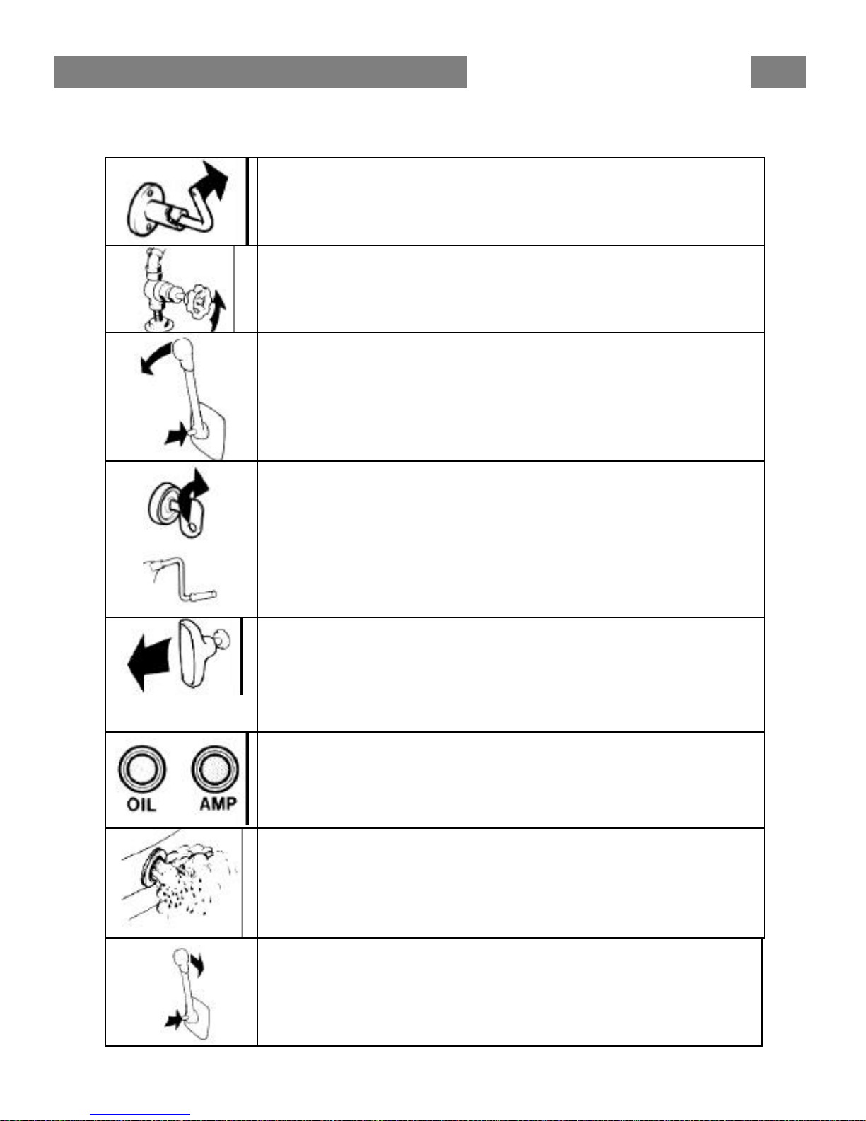
START THE ENGINE
Switch on the main switch. Start the engine room fan (if fitted)
and let it run several minutes before starting the engine.
Check that cocks for fuel and water intake are open. If water in the
boat, use bilge pump and drain the boat.
Disengage the engine speed control from the gear-changing as
follows:
Move the control lever to neutral, push in the red disengaging
button, and move the lever slightly forwards. Release the button.
The lever can now only operate the engine speed.
Check to make sure that the stop control is pushed in.
Turn the key switch one position to the right. The warning lamps
for battery charging and oil pressure should now go on and the
buzzer should sound. Push in and turn the key further to the right
to start the engine. Release the key when the engine starts. Hand
starter. If the engine is started with the starting crank, the
decompression handle (see pages 34-35) on the rocker arm cover
should first be folded up. Return the de-compression handle for
running when the engine has been cranked up in speed.
Cold weather starting
CAV fuel injection pump: Starting is facilitated if the cold-start
control is pulled out. The cold-start control must be pushed in after
the engine has started.
BOSCH fuel injection pump: The engine has a built -in automatic
cold-start device.
Check immediately after starting that the warning lamps for the
oil pressure and battery charging are out and that the siren is quiet.
If any of the lamps are on and the siren is sounding, the
engine must be stopped immediately and an investigation
made.
Run the engine warm at rapid idle. Check to make sure that the
cooling water flows out with the exhaust gases.
NOTE. The key switch should always be switched on as long
as the engine is running to ensure battery charging.
Reduce to idle and check that the engine is running smoothly.
Engage the control lever for gear-changing as follows:
Push in the red dis engaging button and pull the lever back to
neutral. Release the button. The control lever can now be used
both for gear-changing and engine speed.
RUNNING INSTRUCTIONS
RUNNING INSTRUCTIONS
6
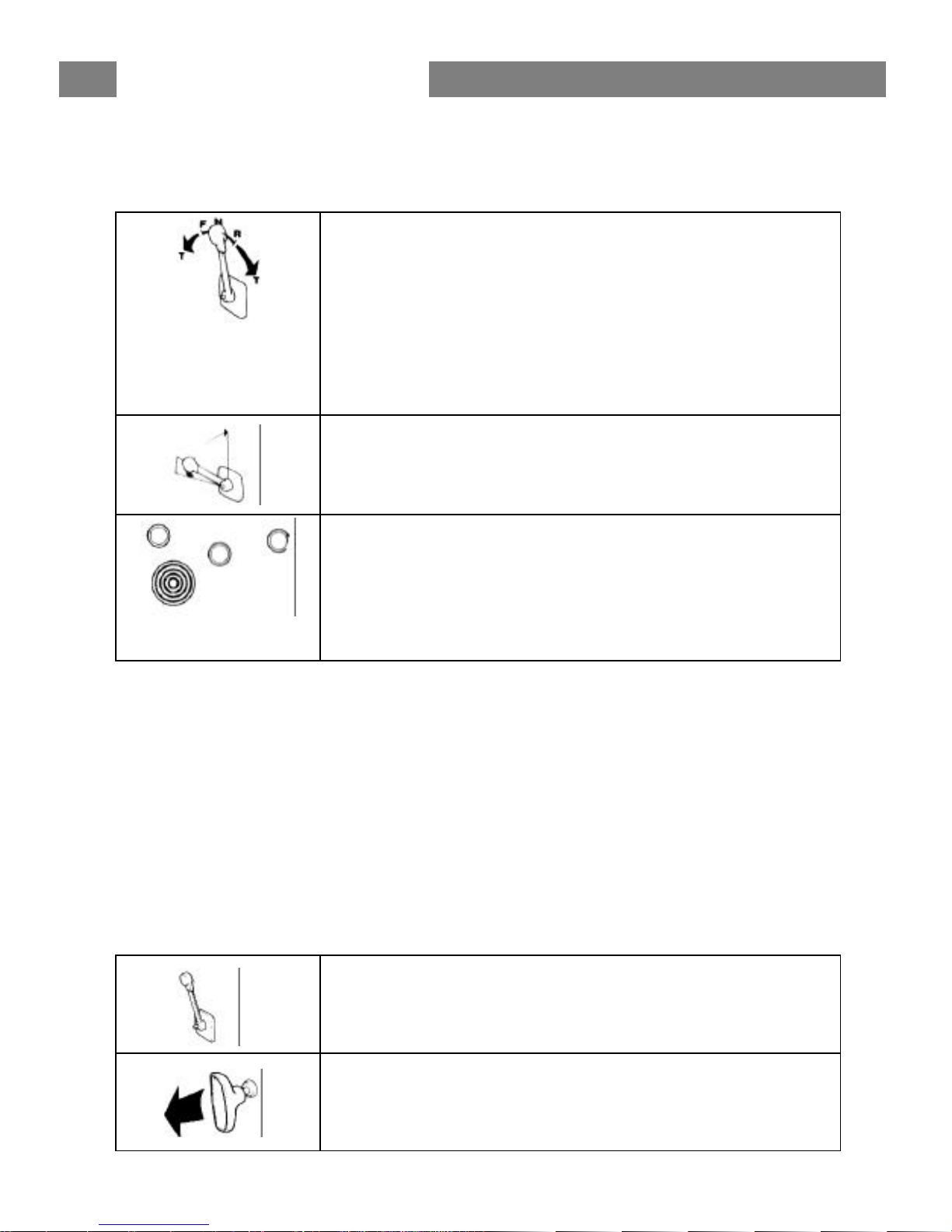
RUNNING
The single lever control contains engine speed as well as gear
shifting functions.
NOTE! If the boat is equipped with a folding type of propeller,
the engine speed must be reduced to idling prior to shifting to
“FORWARD”. Shifting at higher speed might easily damage
the propeller.
F = Forward N = Neutral
R = Reverse T = Throttle
In order to achieve good running economy, the engine should
not be run at maximum engine speed for long periods of time.
Check regularly during running that the warning lamp for
battery charging is out. Should the cooling water temperature
be too high or the oil pressure too low, the buzzer will warn
you, at the same time the relevant warning lamp goes on.
If this happens, the engine must be stopped immediately
and the reason investigated.
SHUTDOWN PROCEDURE
Before shutdown the engine should be allowed to idle for a
few minutes with the control lever in neutral.
Stop the engine by pulling out the stop control when the
engine is idling. Then turn back the key switch to the initial
position.
RUNNING INSTRUCTIONS
7
Folding propeller, S-drive. When switching from engine
operated running to sailing the propeller rotation is stopped by
engaging reverse gear. When sailing maintain the control
lever in the reverse position.
Fixed propeller. When sailing the control lever should be in
the neutral or reverse position. During long sailing trps with
the lever in the neutral position, the engine should be run for
some time every tenth hour in order to ensure lubrication in
the drive or reverse gear.
Switch off the main switch. NOTE! The main switch must
never be switched off until the engine has stopped completely
(the charging regulator can be damaged).
Close the fuel and cooling water cocks if the boat is not going
to be used for some time.
Check for leakage before leaving the beat.
In cold weather and whenever there is a risk of temperatures
below zero, the cooling water must be drained from the engine
and the reverse gear. Close the cock on the cooling water
intake, (S-drive model 110S: See page 19). Close all the
drainage cocks if the boat is left without regular supervision.
An incorrectly performed draining can result in a sunken boat.
(See positions 15 and 16, page 34).
RUNNING INSTRUCTIONS
8
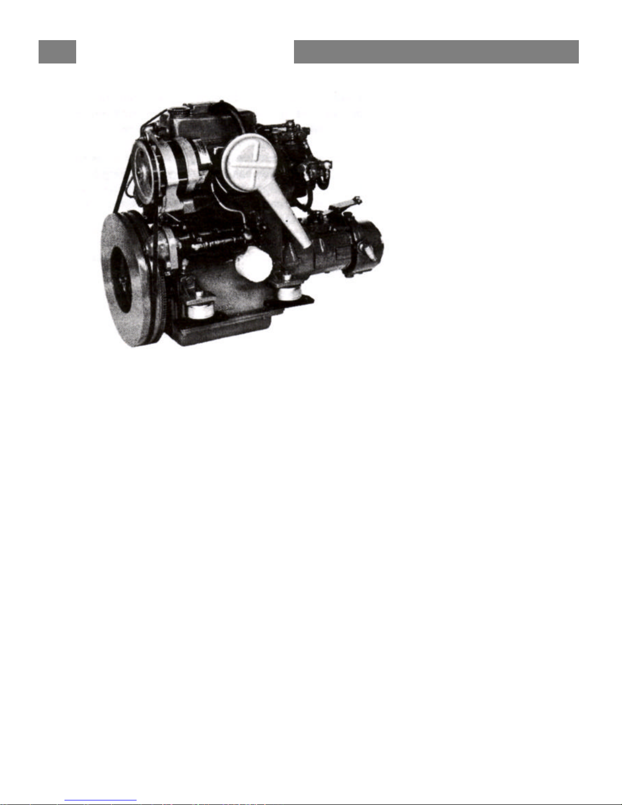
The MD7A is a 2 cylinder, 4-stroke, marine diesel engine with direct injection and sea
water cooling.
ENGINE ASSEMBLY
The engine block and cylinder head are made of cast iron. The engine has overhead
valves.
LUBRICATING SYSTEM
The lubricating system has a full-flow oil filter which cleans the oil before it reaches the
lubrication points. The oil pump has a relief valve which prevents the oil pressure from
becoming excessive.
ELECTRICAL SYSTEM
The engine has a starter motor and an alternator with built-in rectifier. Voltage regulation
is performed by a transistorized regulator, mounted on the alternator. The alternator
makes it possible to charge two batteries independent of each other, if a double-diode
(accessory) is fitted to the alternator.
A main fuse, which can easily be re-connected, is fixed to the engine. It protects the
electrical system from damage in the event of overloading. The wiring diagrams for the
engine and instrument panel are shown on page 32.
TECHNICAL DESCRIPTION
9
FUEL SYSTEM
The fuel system has a feed pump with a fine filter, fuel filter with a fine filter insert,
injection pump and injectors. The feed pump is of the diaphragm type and is equipped
with a hand priming lever.
There is a built -in cold start device in the fuel injection pump. On the CAV fuel injection
pump the cold-start device is operated manually and on the BOSCH fuel injection pump
the cold-start device is operated automatically.
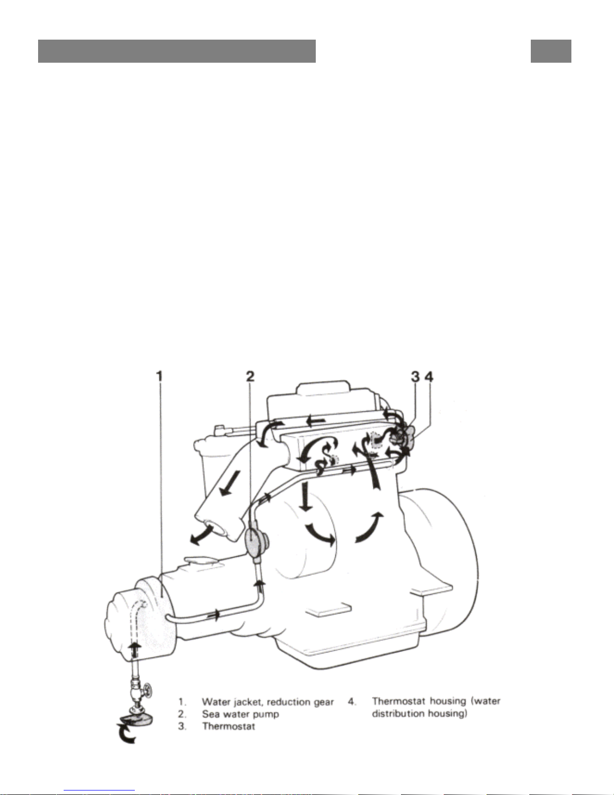
COOLING SYSTEM
The engine is cooled by sea water. The cooling system has a sea water pump and a
water distributor housing with a thermostat.
The sea-water pump has an impeller made of neoprene rubber, which is driven via a
rubber flange from the camshaft.
The thermostat in the water distribution housing regulates the water flow so that water is
always flowing in the exhaust manifold and out in the exhaust elbow regardless of
whether the engine is cold or hot.
TECHNICAL DESCRIPTION
 Loading...