

Volvo Penta MD5A Instruction Book


FOREWORD
Before you start running your new Volvo Penta marine engine, you would be
advised to read through this instruction book carefully. It contains all the
information you need to run and service your engine in the best possible way.
Volvo Penta has built up an extensive service organization with service shops and
specially trained personnel at your service.
Always contact your local Volvo Penta representative for advice and when in need
ot service and parts.
We are convinced that the demands on go od running economy and top
performance, which you have every right to expect of a quality product, will be met
and that your engine will serve you faithfully on many pleasant cruises.
WARRANTY
A warranty certificate is supplied with each engine. It contains the warranty
conditions for the engine and should be studied carefully.
Also included is a report card which is to be completed by the dealer or boat
seller. If our warranty is to apply, however, it is an absolute condition that the
measures given in the “Check and Service Scheme” are carried out and that your
engine and equipment are looked after according to the instructions in this
manual. When in doubt, always get in touch with an authorized Volvo Penta
dealer.
In all correspondence with your dealer and when ordering parts, state the type
designation and serial number of the engine and reverse gear (see starboard side
of engine).

1
Presentation
2
General Information
3 - 4
Running Instructions
5 - 6
Starting the engine
Running instructions
Shutdown procedure
5
6
6
Technical Description
7 - 9
Checks and Service Scheme
10
Checks and Service
11 - 17
Check daily before starting
Check every 14 days
Service every 50 hours of operation
Service every 100 hours of operation
Laying-up and launching
11
11 - 12
12 - 13
13 - 19
20 - 23
Fault Tracing Scheme
24
Technical Data
25 - 26
Wiring Diagram
27
Engine Component Guide
28
Index, alphabetical order
29
CONTENTS
2
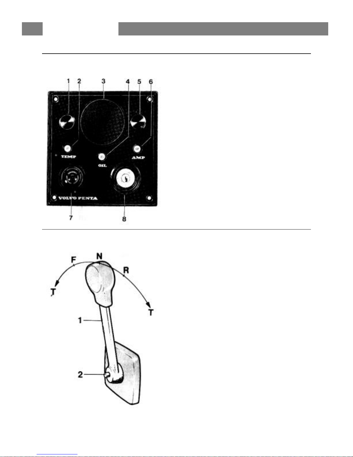
INSTRUMENT PANEL
1. Switch, optional equipment
2. Warning lamp, “Excess temp.”
3. Place for instrument (ø 52 mm opt. equipment)
4. Warning lamp, “No oil pressure”
5. Switch, optional equipment
6. Warning lamp, “No battery charging”
7. Siren, “No oil pressure, excess temp.”
8. Key switch
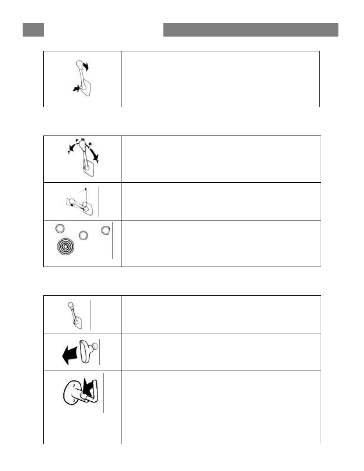
CONTROL SYSTEM
Volvo Penta Single Control System
For side mounting
1. Control lever
2. Disengaging button
Push in the button when the control lever is in neutral
and move the lever a bit forwards. Release button.
The lever is now used only for engine speed control.
To use the lever for both engine speed control and
gear-changing, push in the button and pull back the
lever to neutral.
N = Neutral
F = Control lever in position for running “Forward”
R = Control lever in position for running “Reverse”
T = Engine speed control
PRESENTATION

3
Important information on the function of your engine:
FUEL
Use diesel fuel oil of quality “Autodiesel”. Poorer fuel quality
can cause interruptions in operation.
LUBRICATING
OIL
Use only oil with quality CD (DS) according to the API system.
Volvo Penta oil for diesel engines can be used with
advantage since it meets these quality demands. See under
“Technical Data” concerning the viscosity.
RUNNING-IN
A new marine engine must be run-in with due care during the
first 20 hours of operation. If full output is taken out during this
time, it should only be done for short periods.
Oil change. Change the engine lubricating oil and the oil filter
after the engine has been run for 20 hours. See further under
“Checks and Service”.
ENGINE SPEED Max. speed: 41.7 rev /sec (2500 rev/mm).
For choice of correct propeller, refer to the Volvo Penta propeller diagram. Check the
engine speed with normal load in the boat. In order to utilize the maximum performance
of the engine, an engine speed as high as possible should be chosen but not, however,
greater than 41.7 rev/sec (2500 rev/mm).
NOTE. When the boat has been in the water for some time, the speed and max. rev/mm
can drop due to marine growth on the hull. Prevent marine growth by painting the bottom
of the boat with ant i-fouling paint. See under “Measures taken when launching”.
GENERAL INFORMATION

4
SAFETY EQUIPMENT
Irrespective of whether the boat is being used for long cruises or short bathing trips, the
boat should be equipped with the safety equipment listed below. It can, of course , be
supplemented further according to personal tastes. Investigate at regular intervals to
ensure that there is safety equipment on board and that it is in working order.
LIFE-JACKETS for all on board.
FIRE EXTINGUISHER, approved, at least one and installed where it is easy to get at.
DISTRESS ROCKETS and matches. Packed watertight.
FIRST-AID BOX
TOOLS suitable for the equipment on board.
ON BOARD KIT containing, e.g. impeller, etc.
ANCHOR with line.
RADAR REFLECTOR
RADIO for listening to, e.g., weather reports.
COMPASS which is deviated.
BOAT HOOK and paddle.
MOORING ROPES
FOG-HORN and whistle.
FLOATING ANCHOR
TORCH
PREPARATIONS BEFORE STARTING
Make sure that:
There is no FUEL LEAKAGE
There is no WATER LEAKAGE from engine and hull
There is no OIL LEAKAGE
There is no SMELL OF LP-GAS in the deep cavities in the boat or elsewhere
The OIL LEVEL is correct
There is enough FUEL for the planned voyage
The proper NAUTICAL CHARTS are on board for the planned voyage
If there are some other persons on board, make sure that some of them is able to
operate the boat.
If there are persons on board who have never been on a boat before, tell them where the
life-jackets are located and where the fire-extinguisher is placed. Also tell them anything
more you think necessary from a safety point of view. Should something unexpected
happen during the voyage, it is very often too late to tell those on board how safety
equipment works.
GENERAL INFORMATION
5
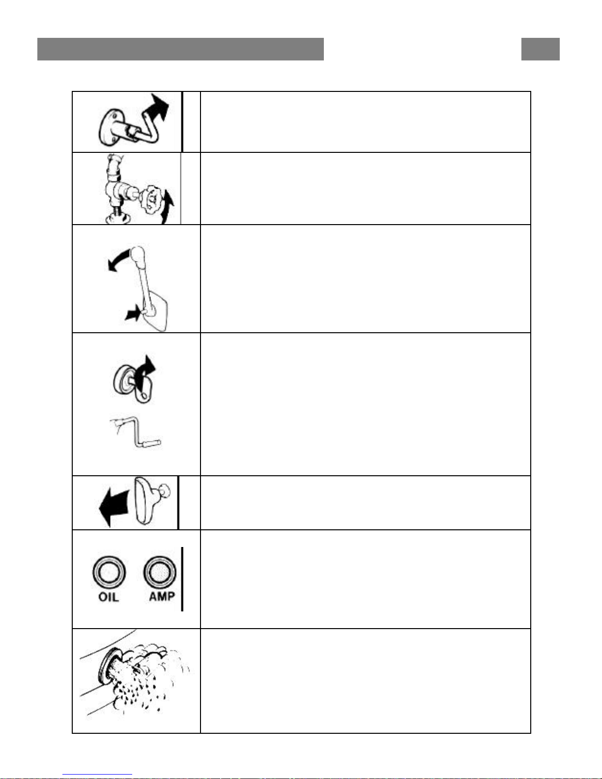
STARTING THE ENGINE
Switch on the main switch. Start the engine room fan (if
fitted) and let it run several minutes before starting the engine.
Open the cock for the cooling water intake.
Disengage the engine speed control from the gearchanging as follows:
Move the control lever to neutral, push in the red disengaging
button, and move the lever slightly forwards. Release the
button. The lever can now only operate the engine speed.
Check to make sure that the stop control is pushed in.
Turn the key switch one stage to the right. The warning
lamps for battery charging and oil press ure should now go on
and the siren should sound. Push in and turn the key further to
the right to start the engine. Release the key when the engine
starts.
Hand starter. If the engine is started with the starting crank,
the decompression handle on the rock er arm cover should first
be folded up. Fold down this handle for running when the
cranking has got the engine up in speed.
Starting in cold weather is facilitated if the cold-start control
is pulled out. Push it in again after a while.
Check immed iately after starting that the warning lamps for
the oil pressure and battery charging are out and that the siren
is quiet. If any of the lamps are on and the siren is
sounding, the engine must be stopped immediately and
an investigation made.
Run the engine warm at rapid idle. Check to make sure that
the cooling water flows out with the exhaust gases.
NOTE. The key switch should always be switched on as
long as the engine is running to ensure that there is
battery charging.
RUNNING INSTRUCTIONS
6
Reduce to idle and check that the engine is running smoothly.
Engage the control lever for gear-changing as follows:
Push in the red disengaging button and pull the lever back to
neutral. Release the button. The control lever can now be
used both for gear-changing and engine speed.
RUNNING
The single lever control has both engine speed and
manoeuvering functions.
F = Forward N = Neutral
R = Reverse T = Engine speed control
To achieve good running economy, the engine should not be
run at max. speed for a longer period.
Make sure that the battery charging warning lamp does not
light when the engine is running The siren will sound and the
respective warning lamp go on if the engine temperature
becomes excessive or the oil pressure too low.
SHUTDOWN PROCEDURE
After shutdown the engine should be allowed to idle for a
couple of minutes or so with the control lever in neutral.
Stop the engine by pulling out the stop control when the
engine is idling. Then turn back the key switch to the initial
position.
Switch off the main switch. NOTE. This switch must never
be switched off until the engine has stopped.
Close the fuel and cooling water cocks if the boat is not going
to be used for some time.
Check for leakage before leaving the beat.
In cold weather and whenever there is risk of icing, the
cooling water should he drained from the engine and reverse
gear. See under “Laying-up and launching”.
RUNNING INSTRUCTIONS
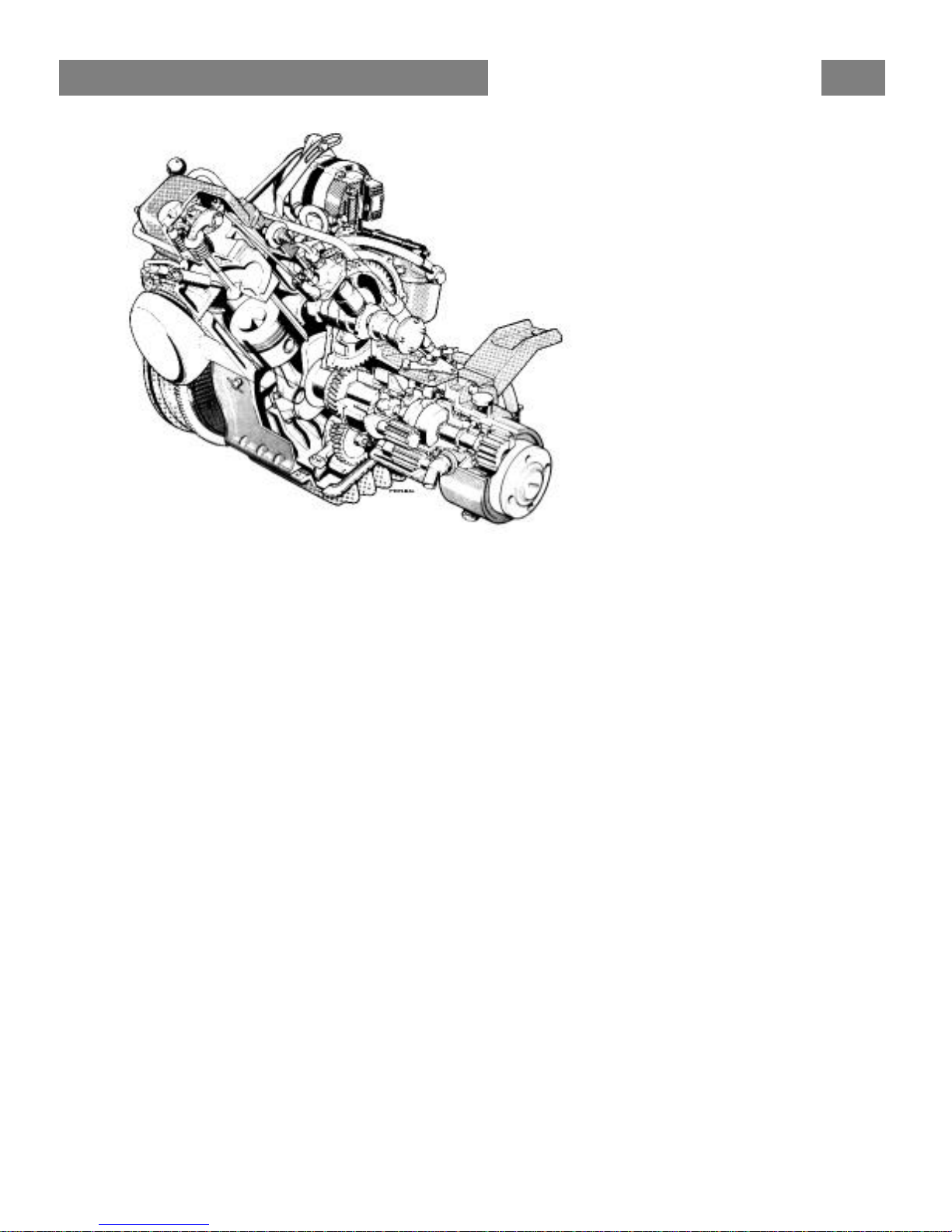
7
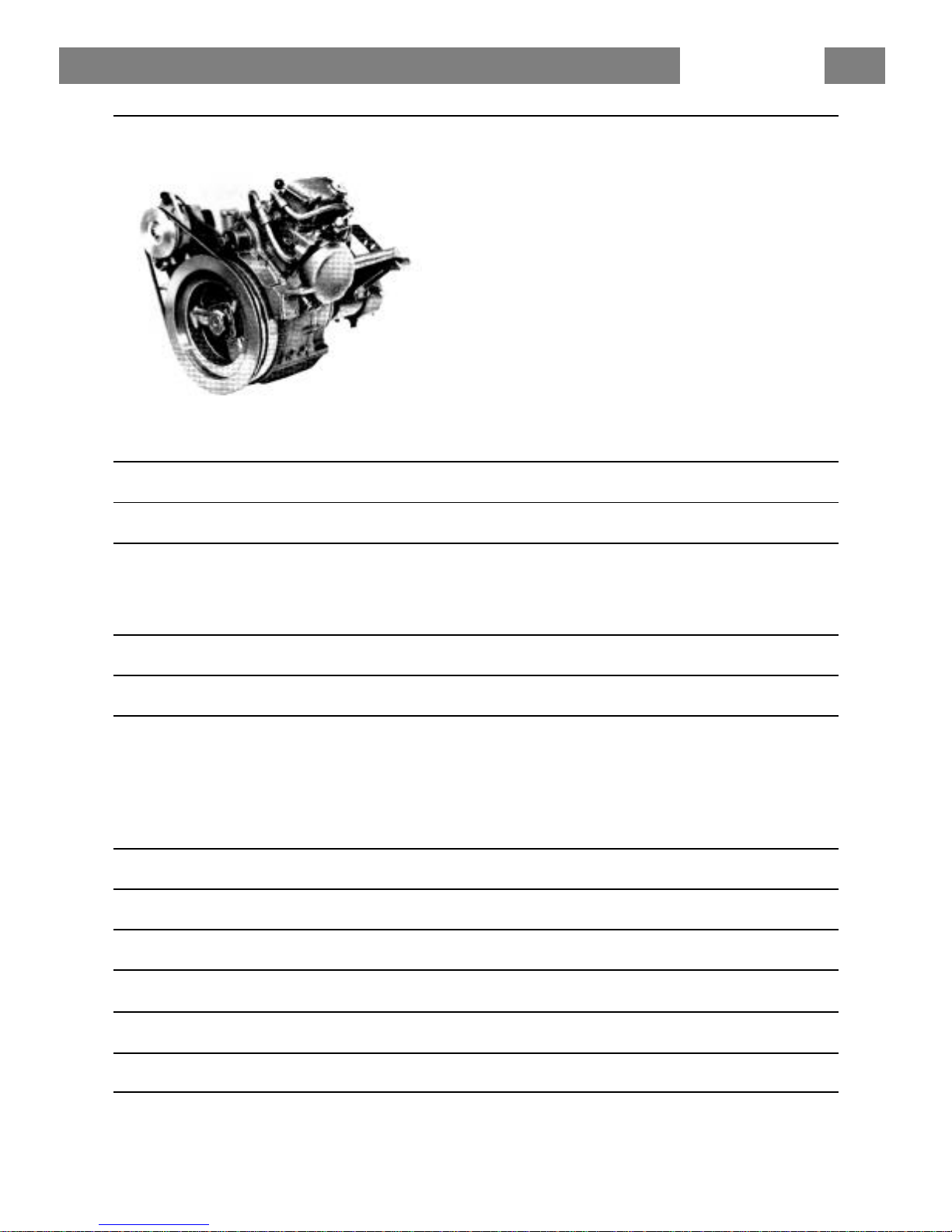
The MD5A is a single-cylinder, 4-stroke, marine diesel engine with direct injection and
sea-water cooling.
ENGINE ASSEMBLY
The engine block and cylinder head are made of cast iron. Cylinder angle 45o. The
cylinder liner is replaceable. The engine has overhead valves.
LUBRICATING SYSTEM
The lubricating system includes a full-flow oil filter which filters all the oil before it reaches
the lubricating points. A relief valve in the oil pump prevents the oil pressure from
becoming excessive.
ELECTRICAL SYSTEM
The engine has a starter motor and alternator with built -in rectifier. Voltage regulation is
taken care of by a transistorized regulator mounted on the alternator. The alternator
makes it possible to charge two battery circuits independent of each other if a charging
distributor (accessory) is fitted on the alternator.
A main fuse, which can easily be re-connected, is fixed to the engine. It protects the
electrical system from damage in the event of overloading. The wiring diagrams for the
engine and instrument panel are shown on page 27.
TECHNICAL DESCRIPTION
 Loading...