

Volvo Penta MD22L, TMD22, MD22, TDM22 Instruction Book

INSTRUCTION BOOK
MD22L, MD22, TDM22

1
Owner’s Manual
Marine Diesel Engines
MD22L, MD22, TMD22
Contents
Safety precautions
Introduction .................................................................... 2
General information ..................................................... 4
Running-in...................................................................... 4
Warranty......................................................................... 5
Certificated engines ....................................................... 6
Instruments................................................................... 9
Control ........................................................................ 12
Operation
Before starting.............................................................. 13
Starting......................................................................... 13
Stopping ....................................................................... 15
In risk of frost................................................................ 15
General engine information
Coolant......................................................................... 16
Venting the fuel system................................................ 17
Emergency stop ...........................................................17
Electrical system ..........................................................18
Fuses ........................................................................... 19
Battery.......................................................................... 19
Maintenance
Check daily before starting........................................... 20
Check every 14 days.................................................... 20
Check every 50 hours of operation ..............................21
Check every 200 hours, or least once a year............... 22
Service every other season.......................................... 24
Other service intervals ................................................. 25
Laying-up
Inhibiting....................................................................... 26
Recommissioning, launching ....................................... 29
Painting ........................................................................30
Propellers ..................................................................... 31
Troubleshooting
Problem - possible causes ........................................... 32
Emergency procedures ................................................ 33
Technical data
Engine .......................................................................... 34
Reverse gear, S-drive ..................................................35
Electrical system
Wiring diagrams ...........................................................36
CALIFORNIA
Proposition 65 Warning
Diesel engine exhaust and some of its constituents are known to
the State of California to cause cancer, birth defects, and other
reproductive harm.
2
Safety precautions
Introduction
This Owner’s Manual contains the information you will
need to operate the engine correctly. Check that you
have the correct Owner’s Manual for your engine.
Read the book carefully before operating or servicing the engine. Incorrect operation or servicing of the
engine could result in personal injury or material damage
as well as damaging the engine itself. If you do not
understand or are uncertain on any operation in this
book, contact your dealer who can explain or demonstrate the procedure for you.
Important
In this manual and on the engine you will find the following special warning symbols.
WARNING! Possible danger of personal injury,
damage to property or mechanical malfunction if
the instructions are not followed.
Read the Owner’s Manual.
Below is a summary of the risks and safety precautions
you should always observe or carry out when operating
or servicing the engine.
Check that the warning or information labels on
the engine are always clearly visible. Replace
labels which have been damaged or painted
over.
Always turn the engine off before starting
service procedures. Avoid burns. Take precautions to avoid hot surfaces and liquids in supply
lines and hoses when the engine has been
turned off immediately prior to starting work on it
and it is still hot.
Reinstall all protective parts removed during
service operations before starting work on the
engine. Make a point of familiarizing yourself
with other risk factors, such as rotating parts
and hot surfaces (exhaust manifold, Turbo unit,
charge pipe, starter heater etc.).
Approaching an engine which is operating is a
safety risk. Loose clothing or long hair can
fasten in rotating parts and cause serious
personal injury.
If the service operation requires that the engine
is operating let your Penta authorized dealer
carry out the work. If working in proximity of an
engine which is operating, careless movements
or a dropped tool can result in personal injury.
Immobilize the engine by turning off the power
supply to the engine at the main switch (breakers) so it is impossible to start, and lock the
switch (breakers) in the OFF position before
starting work. Set up a warning notice at the
engine control point or helm.
Engines with Turbo compressors: Never start
the engine without installing the air cleaner
(ACL). The rotating compressor parts in the
Turbo can cause serious personal injury.
Foreign objects entering the intake ducts can
also cause mechanical damage.
Engines with intake air pre-heating: Never use
starting spray in the air intake. Use of such
products could result in an explosion in the air
intake pipe due to the hot-spot pre-heater.
Danger of personal injury.
Do not open the filler cap for the engine coolant
(freshwater cooled engines) when the engine is
hot. Steam or hot engine coolant can be ejected
and any pressure in the system will be lost.
Open the filler cap slowly and release coolant
system pressure (freshwater cooled engines), if
the filler cap or drain cock must be opened, or if
a plug or engine coolant line must be removed
on a hot engine. Steam or hot coolant can be
ejected.
Stop the engine and close the bottom valve
before carrying out operations on the cooling
system.
Only start the engine in a well-ventilated area. If
operating the engine in a closed area ensure
that there is exhaust ventilation leading out of
the work area to remove exhaust gases and
crankcase ventilation emissions.
Anti-corrosion agents are hazardous to health.
Read the instructions on the product packaging!
Anti-freeze agents are hazardous to health.
Read the instructions on the product packaging!
Certain engine conservation oils are inflammable. Some of them are also dangerous if
breathed in. Ensure good ventilation in the work
place. Use a protective mask when spraying.
3
Hot oil can cause burns. Avoid getting hot oil on
the skin. Ensure that the lubrication system is
not under pressure before carrying out any
work. Never start or operate the engine with the
oil filler cap removed, otherwise oil could be
ejected.
Never allow an open flame or electric sparks
near the battery area. Never smoke in proximity
to the batteries. The batteries give off hydrogen
gas during charging which when mixed with air
can form an explosive gas. This gas is easily
ignited and highly volatile. Incorrect connection
of the battery can cause sparks sufficient to
cause an explosion with resulting damage. Do
not shift the connections when attempting to
start the engine (spark risk) and do not lean
over any of the batteries. Refer to instructions in
the Owner’s Manual.
Always ensure that the Plus (positive) and
Minus (negative) battery leads are correctly
installed on the corresponding terminal posts on
the battery. Incorrect installation can result in
serious damage to the electrical equipment.
Refer to the wiring diagrams.
Always use protective goggles when charging
and handling the batteries. The battery electrolyte contains extremely corrosive sulfuric acid. If
this should come in contact with the skin,
immediately wash with soap and plenty of
water. If battery acid comes in contact with the
eyes, immediately flush with water and obtain
medical assistance.
Turn the engine off and turn off the power at the
main switches (breakers) before carrying out
work on the electrical system.
Clutch adjustments, where a clutch is fitted,
must be carried out with the engine turned off.
Use the lifting eyes fitted on the engine/reverse
gear when lifting the drive unit. Always check
that the lifting equipment used is in good
condition and has the load capacity to lift the
engine (engine weight including reverse gear
and any extra equipment installed).
To ensure safe lifting and avoid damage to
components installed on the top of the engine
use an adjustable lifting beam. All chains and
cables must run parallel to each other and as
perpendicular as possible to the upper side of
the engine.
If extra equipment is installed on the engine
which alters its center of gravity a special lifting
device is required to obtain the correct balance
for safe handling.
Never carry out work on an engine suspended
on a hoist.
The components in the electrical system, the
ignition system (gasoline/petrol engines) and in
the fuel system on Volvo Penta products are
designed and manufactured to minimize risks of
fire and explosion.
Using parts that are not Original Volvo Penta
parts which do not correspond to the demands
above, can result in fire or explosion on board.
Any type of damage which is the result of using
replacement parts that are not original Volvo
Penta replacement parts for the product in
question will not be covered under any warranty
or guarantee provided by AB Volvo Penta.
Fuel filter replacement should be carried out on
a cold engine in order to avoid the risk of fire
caused by fuel spillage on the exhaust manifold.
Always cover the alternator, if it is located under
the fuel filter. The alternator can be damaged by
spilled fuel.
Always use protective gloves when detecting
leaks. Liquids ejected under pressure can
penetrate the body tissues and cause serious
injury. Danger of blood poisoning.
Always use fuels recommended by Volvo Penta.
Refer to the Owner’s Manual. Use of fuels that
are of a lower quality can damage the engine.
On a diesel engine poor quality fuel can cause
the actuating rod to hang and the engine to
overrev with resulting risk of damage to the
engine and personal injury. Poor fuel quality can
also lead to higher maintenance costs.
Observe the following when cleaning with highpressure water jets. Never point the water jet at
seals, rubber hoses or electrical components.
Never use high pressure jets when washing the
engine.

4
Welcome aboard
Thank you for choosing a Volvo Penta marine engine.
Volvo Penta have been building marine engines since
1907. Quality, operating reliability and innovation have
made Volvo Penta a world leader in the marine engine
industry.
As owner of a Volvo Penta marine engine we would also
like to welcome you to a worldwide network of dealers
and service workshops to assist you with advice, service
requirements and spare parts. Please contact your
nearest authorized Volvo Penta dealer for assistance.
We would like to wish you many pleasant voyages.
AB VOLVO PENTA
Technical Information
Your new boat
Every new boat has it own special characteristics. Even
experienced boat owners are advised to note carefully
how the boat behaves at different speeds, weather
conditions and loads. If your boat and engine combination permit high-speed use, we strongly recommend that
a safety breaker is fitted, regardless of the type of boat. If
your boat is not fitted with a safety breaker contact your
Volvo Penta dealer who can assist you in selecting one.
Running-in
A new marine engine requires a running-in period of 20
operating hours. Run the engine at varying engine
speeds, but not over a maximum of 3/4 throttle opening
for the first two hours. For the next 8 hours run the
engine in the same way, but with max. 2 minute periods
at wide open throttle (WOT). During the final 10 hours
increase wide open throttle periods to 5–10 minutes at a
time. Reduce the throttle opening to idle periodically to
allow the engine temperature to drop. During the running-in period never run the engine for long periods at a
constant engine speed. It is normal for the engine to use
more engine oil during the running-in period. Make a
point of checking the engine oil level more frequently
during the running-in period than during normal operation. Carry out the First Service Inspection after the initial
20-hour running-in period.
General Information
Fuel and lubricants
Only use lubricants and fuels recommended under
“Technical Data”. Use of other classifications can cause
malfunctions and reduced service life.
Spare parts
WARNING! The components in the electrical
system and in the fuel system on Volvo Penta
products are designed and manufactured to
minimize the risk of fire and explosion.
Using parts that are not Original Volvo Penta
parts and which do not correspond to the
demands above, can result in fire or explosion
on board. Any type of damage which is the
result of using replacement parts that are not
original Volvo Penta replacement parts for the
product in question will not be covered under
any warranty or guarantee provided by
AB Volvo Penta.
Safety
Everyone wants and expects to have a problem-free and
pleasant time when they take their boat out. To help you
do this we have provided a check-list below which can of
course be added to according personal experience. A
major area is naturally the engine, its equipment and that
the boat in general is properly maintained.
Planning your trip
– Get out up-to-date charts for the route planned
– Calculate distance and fuel consumption
– Note down if there are fuel points on your planned
course
– Tell friends or relatives about your trip plans
Boat equipment
– Rescue and emergency items such as life-vests and
signal rockets. Does everyone know where they are?
– Spare parts on board, for example: Kit with water
pump impeller etc.
– Proper tools for the equipment
– Fire extinguisher (checked and charged)

5
Our joint responsibility
Volvo Penta continually commits a considerable part of
its development resources towards minimizing the
environmental impact of its products. Examples of areas
where we are always looking for improvements are;
exhaust emissions, sound levels and fuel consumption.
Regardless of whether your Volvo Penta engine is
installed in a boat used for pleasure or in commercial
operation, incorrect operation or improper maintenance
of the engine will result in disturbance or damage to the
environment.
In this Owner’s Manual there are a number of service
procedures, which, if not followed will lead to a deterioration of engine characteristics with regard to how it effects
the environment, its service life and cost of operation.
Always follow the recommended service intervals and
make a habit of checking that the engine is operating
normally every time you use it. One example is excessively smoky exhaust. Contact an authorized Volvo
Penta workshop if you cannot correct the fault yourself.
Bear in mind that most of the chemicals used around
boats are harmful to the environment if used incorrectly.
Volvo Penta recommends the use of bio-degradable
degreasing agents for all cleaning. Always dispose of
engine and transmission oil waste, old paint, degreasing
agents and cleaning residue etc. at proper disposal
areas so they do not harm the environment.
Adapt speed and distance during your boat trips so that
swell and noise generated by the boat do not disturb or
harm wildlife, moored boats, landing stages etc. Wherever you land or cruise, please show consideration and
always leave the areas you visit as you would like to find
them yourself.
Warranty and guarantee
A Service and Warranty Book with conditions for Volvo
Penta’s International Limited Warranty is supplied with
every engine. Contact your nearest Volvo Penta dealer
or importer for your copy if you have not received one.
Some markets can have other warranty conditions
depending on national legislation and regulations. These
conditions are provided by the Volvo Penta importer or
distributor for the market in question. If you wish to have
a copy of the conditions please contact your local Volvo
Penta representative.
Warranty Registration Card
The Warranty Registration Form (North American
market) or Warranty Card (other markets) should always
be filled out and sent in by the vendor. Make sure that
this has been done, since refusal of warranty can occur if
no proof of the delivery date can be provided.
Maintenance and care
– PDC (Pre Delivery Commissioning) delivery undertaking, for marine engines: PDC enables us to ensure that
Volvo Penta products operate correctly after installation
in a boat, and further that the end-user gets acquainted
with the product, its functions and care (refer to the
Warranty and Service book). Delivery undertaking “PDC“
is carried out at the time of the delivery of the boat to the
end-user. The cost of this work is covered by the Volvo
Penta International Limited Warranty.
– First Service inspection, for marine engines: A first
Service Inspection must be carried out after operating
the engine for 20–50 hours or within 180 days from the
delivery date, or the end of the first season, whichever
occurs first. Labor and material costs in connection with
the First Service Inspection are not covered by the Volvo
Penta International Limited Guarantee (for checklist see
your Warranty and Service book).
Regular maintenance should be carried out after the First
Service Inspection in accordance with the maintenance
scheme in this book. Any work carried out in addition to
maintenance services should be documented (refer to
the Warranty and Service book)
It is an absolute condition for the Volvo Penta International Limited Warranty to apply that the PDC Delivery
undertaking and First Service Inspection have been
carried out by an authorized Volvo Penta Service dealer.
Volvo Penta Service
Volvo Penta has a comprehensive dealer network that
offers both service and spare parts for Volvo Penta
engines. Volvo Penta dealers are carefully selected and
then trained in order to provide customers with professional assistance on engine service and repairs. These
dealers have the special tools required to carry out the
work and the test equipment that ensures a high service
standard. They are required to keep a stock of Volvo
Penta Original Spare Parts and accessories that cover
most requirements. When ordering service or spare parts
always quote the complete engine and/or drive/reverse
gear model designation and serial number. These are
stated on the engine product plate and on a label on the
engine valve cover.

6
© 1995 AB VOLVO PENTA
All rights to changes or modifications reserved.
Printed on environmentally-friendly paper
IMPORTANT! Use only VOLVO PENTA original
spare parts. The use of spare parts other than
VOLVO PENTA original spare parts will
invalidate AB VOLVO PENTA’s responsibility
for the engine specification being in accordance with the certificated variant. VOLVO
PENTA accepts no responsibility or liability for
any damage or costs arising through the use of
replacement parts other than original VOLVO
PENTA replacement parts for the product in
question.
Identifying Numbers
Immediately after you have taken delivery of your boat,
make a note of the serial number and model designation
of the engine and drive as well as the shield or reverse
gear. Include the serial number and model designation of
the boat and any extra equipment. This information is
necessary when you contact your Volvo Penta or boat
sales representative for service and spare parts. Take a
copy of the information and keep it in a safe place so it is
available should the boat be stolen.
Engine type .....................................................................
Serial No. ........................................................................
Drive type ........................................................................
Serial No. ........................................................................
Reverse gear type...........................................................
Serial No. ........................................................................
Propeller designation ......................................................
Boat type .........................................................................
Serial No. ........................................................................
Other equipment .............................................................
.........................................................................................
.........................................................................................
.........................................................................................
.........................................................................................
.........................................................................................
Certificated engines
Important information for engines certificated for
Lake Constance and Switzerland
All Volvo Penta engines and products are developed to
minimize environmental impact.
National and regional legislation is not identical in all the
markets where Volvo Penta sells its products. Occasionally legislation requires that we build special engine
variants, or that an engine must be approved in advance,
that is, certificated by the local authorities.
An engine with certification means that we, as the
manufacturer, guarantee that all engines manufactured
are of the same type as the certificated and approved
example. Certification is not only a requirement covering
engines from the factory, but also that engines in use
must meet the environmental demands set for that
engine. In order for Volvo Penta as the manufacturer to
take responsibility for engines in use, certain requirements pertaining to service and spare parts must be met.
We do not wish to discourage owners from carrying out
service work themselves, rather the opposite since an
owner can quickly notice if an engine is not operating
normally. However, a number of service operations
demand access to special expertise, workshop manuals,
special tools and other equipment designed for the
engines. These service operations may only be carried
out by an authorized Volvo Penta Service workshop.
Always contact your Volvo Penta dealer if you are not
sure about anything concerning your engine’s function or
maintenance.
As an owner or operator of a certificated Volvo Penta
engine it is important that you are aware of the following:
l The Service Intervals and maintenance operations
recommended by Volvo Penta must be followed.
l Only Volvo Penta Original Spare parts intended for
the certificated engine may be used.
l Service work on the ignition system, ignition settings
and fuel injection system (gasoline/petrol) or injection
pumps, pump settings and injectors (diesel) must
always be carried out by an authorized Volvo Penta
workshop.
l The engine may not be altered or modified in any
way, with the exception of accessories and service
kits developed by Volvo Penta for that engine.
l No modifications to the exhaust pipes and air supply
ducts for the engine room (ventilation ducts) may be
undertaken as this may effect exhaust emissions.
l Any seals on the engine may not be broken other
than by authorized persons.
7
Introduction
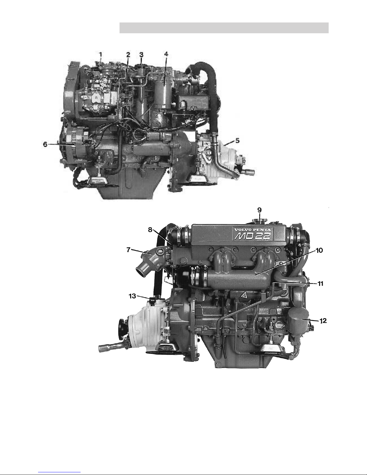
MD 22L, MD 22, TMD 22 / MS2L, MS2A
1. Fuel liftpump
2. Oil dipstick
3. Filler cap for lubricating oil
4. Fuel filter
5. Reverse gear serial number
6. Alternator
7. Exhaust outlet
8. Raw water pump
9. Filler cap
10. Induction manifold
11. Pipe for oil bilge pump
12. Oil filter
13. Oil dipstick, reverse gear
8
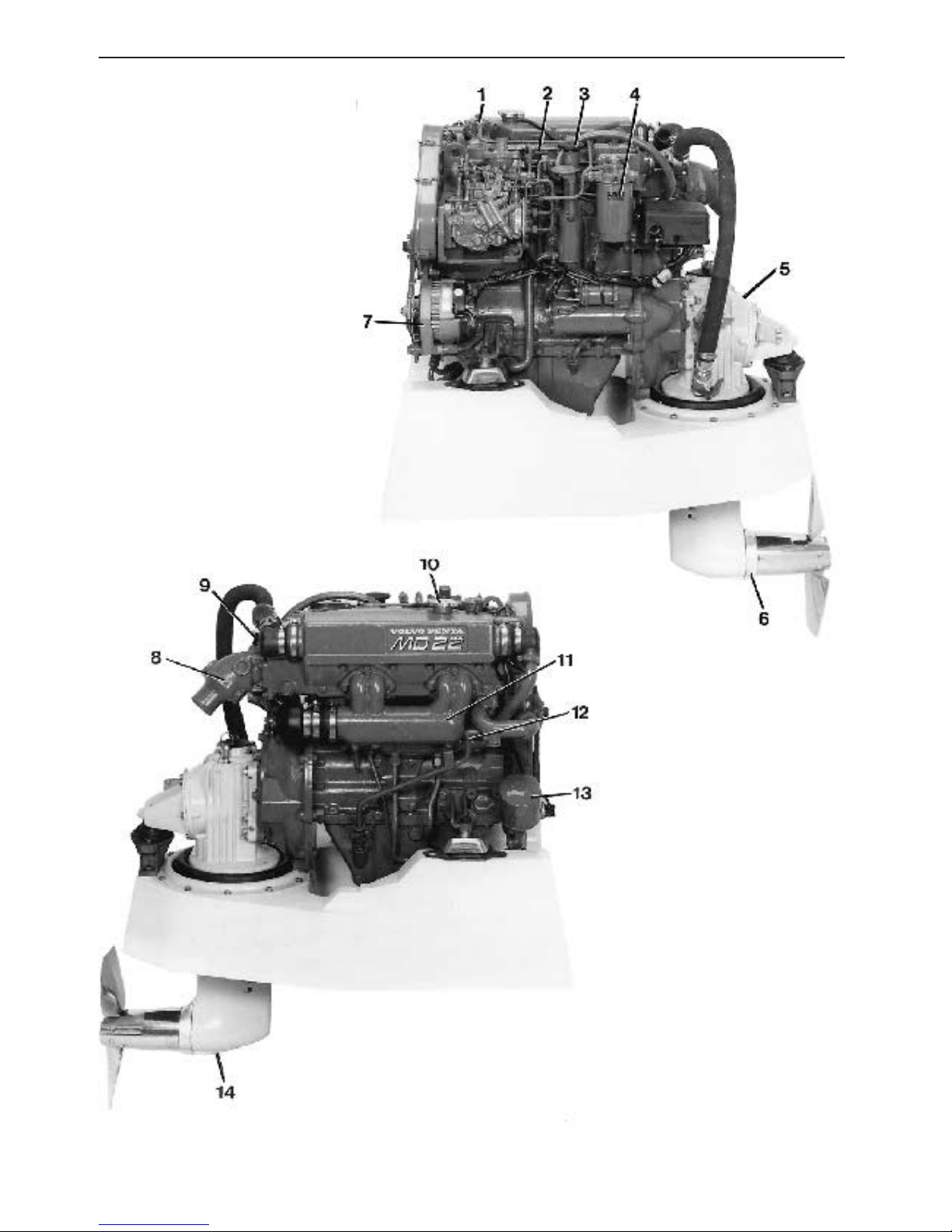
MD 22L, MD 22, TMD 22 /120S
1. Fuel liftpump
2. Oil dipstick
3. Filler cap for lubricating oil
4. Fuel filter
5. S-drive serial number
6. Zinc anode
7. Alternator
8. Exhaust outlet
9. Raw water pump
10. Filler cap
11. Induction manifold
12. Pipe for oil bilge pump
13. Oil filter
14. Oildrainage, drive
9
Instruments
6
7
4
1 2 5 3
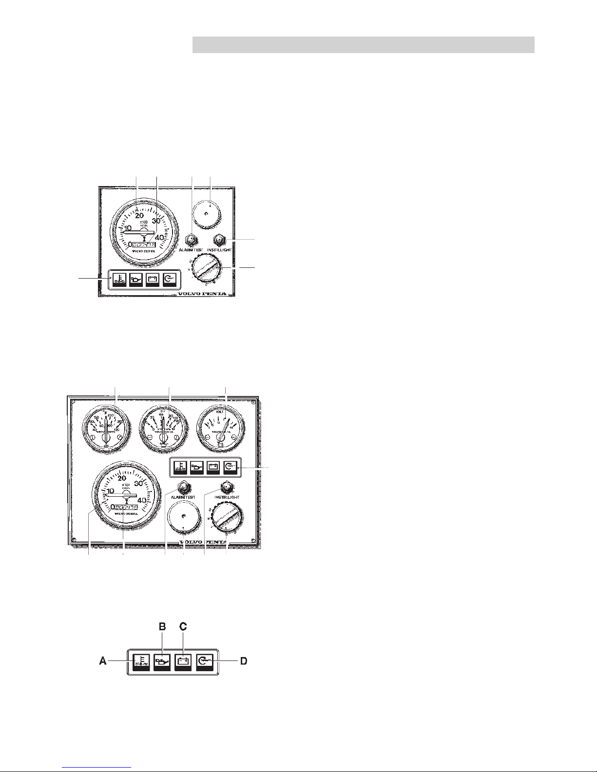
Instrument panel De luxe
*Note. Rev. counter with built-in hour counter is optional.
4
Instrument panel (standard)* with key switch
*Note. Rev. counter with built-in hour counter is optional.
Warning display
8910
1 2 5 3 6 7
There are two types of instrument panels, “Standard” and
“De luxe”.
Standard
1. Rev. counter
The rev. counter shows the engine speed. Multiply the
value by 100 to calculate revolutions per minute.
Full throttle: operating range,
MD22: 3200– 4000r/min.
MD22L: 2700–3000 r/min.
TMD22 : 4100–4500 r/min.
2. Hour counter
Shows the engine operating time in hours and tenth of an
hour.
3. Alarm (siren)
Sounds when lubricating oil pressure is too low
(engine), when coolant temperature is too high or
there is a loss of charge.
4. Warning display
The display has four “windows”. If the acoustic alarm
comes on, one of windows “A−C” starts to blink (red)
to show the cause of the alarm.
A. Coolant too hot. Reduce the speed to idling (in
neutral) until the temperature decreases.
Investigate the cause of the alarm (e.g. restrict-
ed water supply to the engine). Stop the engine if
the temperature does not decrease.
B. Lubricating oil pressure too low. Stop the engine
immediately and locate the cause of the alarm.
C. Alternator not charging.
D. Pre-heating (indicator lamp comes on when glow
plugs are on).
NB. This lamp also works as a filament guard for
the glow plugs. This will also be lit when the key
switch is in position I (operating position) if there is
a fault in the system (break).
Lamp Test (before starting):
All the warning lights will be on but will not flash (for a
maximum of 20 seconds) after the key switch has
been put in the “Running” position (I). The warning
light for high coolant temperature (A) will then go off.
10
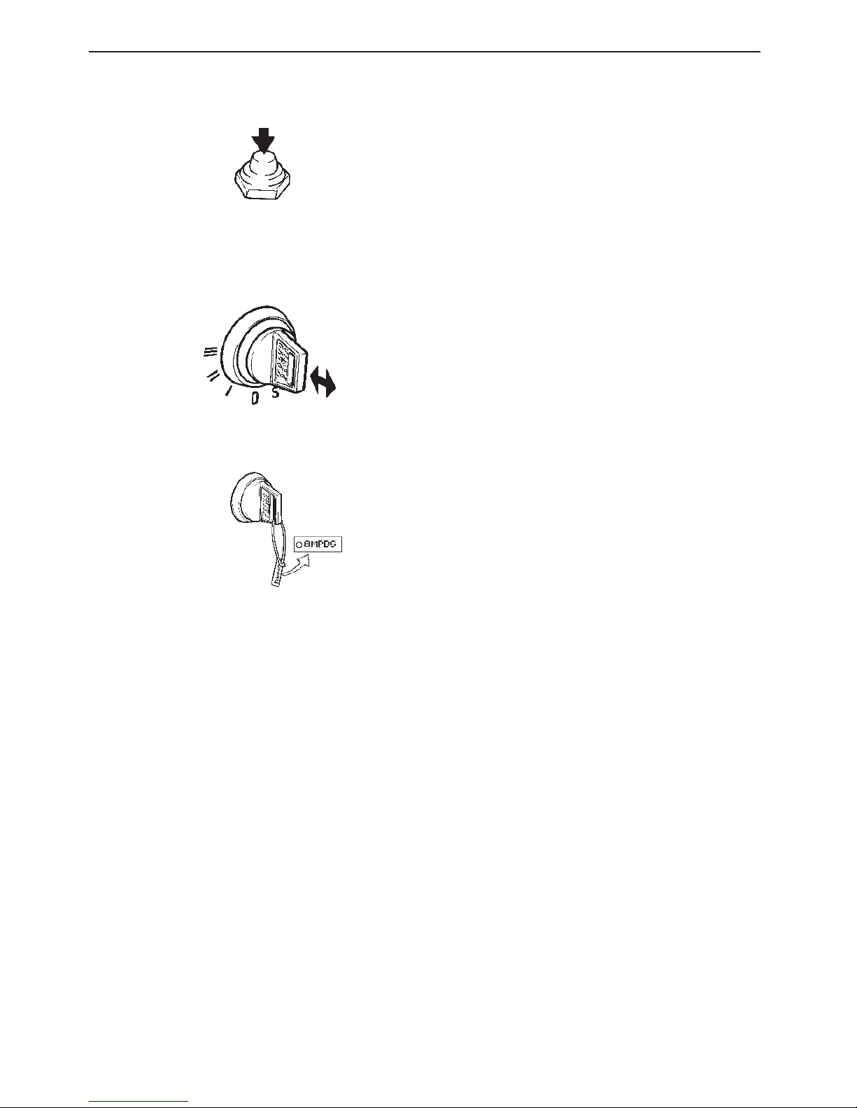
5. Pressure switch – Alarm test / Acknow-
ledge
No alarm: Alarm test (all warning lights on – not
flashing– and the siren sounding).
Alarm: Acknowledgement of alarm.*
*The siren stops sounding, but the warning light continues to
flash until the fault has been rectified. If a new alarm condition
arises, the siren will sound again and the next warning light will
also start to flash, and so on.
6. Pressure switch
−−
−−
−instrument lighting
7. Key switch
The key switch has five positions, including 0:
Pos.0 = Key can be inserted and removed.
S = The mechanical restart block disengages.
The key springs back automatically to 0.
I = Running position. Key springs automatically
back to running position after starting.
II = “Glow” position.
III = Start position (starter motor comes on). Let
the key go as soon as the engine has started.
See also the starting instructions on page 13.
A disc is provided with the keys which gives the key
code. This code must be stated when ordering new
keys. Do not keep the number disc on the boat. Do
not allow unauthorised persons access to the code.
8.Temperature gauge
The temperature gauge should normally show approx.
75-95oC (167-203oF) during normal operation. The
acoustic alarm comes on when the coolant is too hot.
If an alarm is emitted, reduce the speed to idling
(in neutral) until the temperature decreases.
Investigate the cause (e.g. restricted water supply to
the engine). Stop the engine if the temperature
does not decrease.
9. Oil pressure gauge
The oil pressure gauge should normally show approx.
150-500 kPa (1.5-5 kp/cm2 = 21-71 lbf/in2) during
operation. It is normal for the gauge to show a lower
value when the engine is idling.
The acoustic alarm comes on when the oil pressure is
too low. When the alarm sounds, stop the engine
immediately and locate the cause.

11
10. Voltmeter
The voltmeter shows the voltage in the starter battery
circuit. The voltage should be about 14V during operation. The voltage is about 12V when the engine is off.
Supplementary warning display
The display has four “windows”. If the acoustic alarm
comes on, one of the windows starts to blink (red) to
show the cause of the alarm.
E. Lubricating oil level too low.* Top up with oil to the
correct level before start.
F. Coolant level too low.* Top up with coolant to the
correct level before start.
G. Water in extra fuel pre-filter.** Drain the water in
the filter.
H. Extra alarm for monitoring any optional function.***
* Warning function only when engine is stopped and key
switch is in position I
** Warning function both when engine is stopped and running.
Key switch in position I
*** Warning function only when engine is running. Key switch in
position I
Instrument sets
The instrumentation is also supplied separately in sets.
These sets include the following three smaller panels
for starting and stopping and for utilising the alarm
functions.
Control panel for pilot house (main panel)
Control panel for alt. operating position
N.B.: The key switch in the pilot house control panel
must be in position I (operating position) for starting to
be carried out from the alt. operating position. The preheating can only be engaged via the key switch on the
panel in the pilot house.
11. Starter button. The starter motor is engaged when
this button is pressed. Release the button as soon
as the engine has started.
12. Stop button. The stop solenoid is engaged when
this button is pressed.
11
12
5
6
5
6
12
Controls
Controls
The Volvo Penta single-lever control combines the
throttle and gear shift functions in one lever. When
starting, for example, the gear change function can
easily be switched off so only the engine speed is
affected by the lever. When manoeuvring the boat
backwards or forwards, the control mechanism makes
the engine speed drop to idling speed when the gears
are changed.
The control lever has an adjustable friction brake. A
neutral position switch which allows the engine to be
started only when reverse gear is not engaged is
available as an extra.
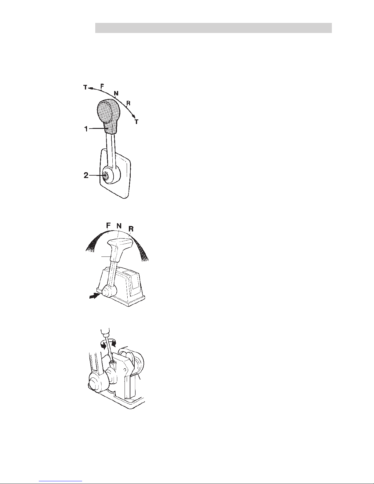
Manoeuvring takes place as follows:
Lever (1) for reverse gear/S-drive manoeuvres and
engine speed control.
Position N = neutral position.
From N to F – reverse gear engaged for forward
running.
From N to R – reverse gear engaged for reversing.
T = affects engine speed.
Disengaging the reverse gear from the control:
Place the lever (1) in the neutral position “N”. Press
the button (2), push the lever forwards slightly and
release the button. The lever will now only affect the
speed.
The lever automatically reconnects the reversing
function when it is moved back to the neutral position.
The speed can then be adjusted and forward/reverse
manoeuvres executed. Ensure that the reverse
gear/S-drive is not engaged unintentionally.
•
1
2
 Loading...