

Contents
| Safety Precautions3- | 7 |
| Introduction8-4 | 9 |
| Running-in | 8 |
| Fuel and oils | 8 |
| Certified engines | 8 |
| Warranty | 9 |
| ~ | |
| 2 | |
| MD2010, MD2020 |
U
J |
| MD2030, MD2040 1 | 1 |
| Identification number 12 | 2 |
| Instrumentation | 5 |
| Controls 10 | 6 |
| Starting the engine 17–19 | 9 |
| Before starting | 7 |
| Starting using auxiliary batteries | ģ |
| Starting using auxiliary batteries | 0 |
| Operation | 1 |
| Checking instruments 20 | 0 |
| Cruising speed | 0 |
| Maneuvering 2 | 1 |
| When sailing 2 | 1 |
| Stopping the engine | 2 |
| After stopping the engine | 2 |
| 2 | |
| Cold weather precautions 2 | 2 |
| 2 | |
| 3 | |
| Maintenance | 5 |
| Engine, general | 4 |
| Lubrication system 26 | 6 |
| Cooling system 27 | 7 |
| Fuel system 32 | 2 |
| Electrical system 34 | 4 |
| Wiring Diagrams | 9 |
| S drive and reverse gear 43 | 3 |
| Foldingpropeller 48 | 5 |
| Laying up and launching 46- | 48 |
|---|---|
| Inhibiting | 46 |
| Bringing out of storage | 47 |
| Painting the drive and underwater hull | 48 |
| Fault-tracing | 49 |
| Technical Data | 51 |
| Technical Data |
51
50 |
| Technical Data |
51
50 50 |
| Technical Data |
51
50 50 50 |
Safety Precautions
Read this chapter carefully. It concerns your safety. This section describes how safety information is presented in the Instruction Manual and on the engine. It also gives a general account of basic safety precautions to be taken when operating the boat and maintaining the engine.
Check that you have the correct Instruction Manual before you read on. If this is not the case please contact your Volvo Penta dealer.
Safety precautions to be taken when operating the boat
▲ Your new boat
Read Instruction Manuals and other information supplied with your new boat. Learn to operate the engine, controls and other equipment safely and correctly.
If this is your first boat, or is a boat type with which you are not familiar, we recommend that you practice controlling the boat in peace and quiet. Learn how the boat behaves at different speeds, weather conditions and loads before casting off for your "real" maiden voyage.
Remember that the person driving a boat is legally required to know and follow the current rules regarding traffic and safety at sea. Make sure you know the rules that apply to you and the waters you are sailing in by contacting the relevant authorities or organization.
A good piece of advice is to take a course in seamanship. We recommend that you contact your local boating organization to find a suitable course.
▲ Accidents
Statistics show that poor maintenance of boats and engines and a lack of safety equipment are often the cause of accidents at sea.
Ensure that your boat is maintained in accordance with the relevant Instruction Manual and that the necessary safety equipment is on-board and is serviceable.
▲ Daily checklist
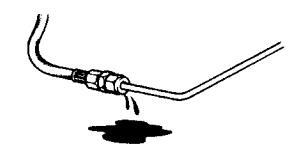
Make a habit of checking the engine and engine compartment visually before operating the boat ( before the engine is started ) and after operating the boat (after the engine has been stopped). This will help you to quickly detect fuel, coolant and oil leaks and spot anything else unusual that has or is about to happen.
Avoid violent and unexpected changes in course and gear engagement. There is a risk that someone aboard will fall down or overboard.
A rotating propeller can cause serious injury. Check that nobody is in the water before engaging ahead or astern. Never drive near bathers or in areas where people could be in the water.
Avoid trimming an outboard drive too much, as steering will be severely reduced.
A Refueling
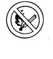
When refueling there is always a danger of fire and explosion. Smoking is forbidden and the engine must be switched off.
Never overfill the tank. Close the fuel tank filler cap properly.
Only use the fuel recommended in the Instruction Manual. The wrong grade of fuel can cause operating problems or cause the engine to stop. On a diesel engine poor quality fuel can cause the control rod to seize and the engine to overrev with a resultant risk of damage to the engine and personal injury.
▲ Safety breaker
We recommend that you install and use a safety breaker (accessory), especially if you boat can travel at high speeds. The safety breaker stops the engine if the driver falls down and loses control over the boat.
⚠ Carbon monoxide poisoning
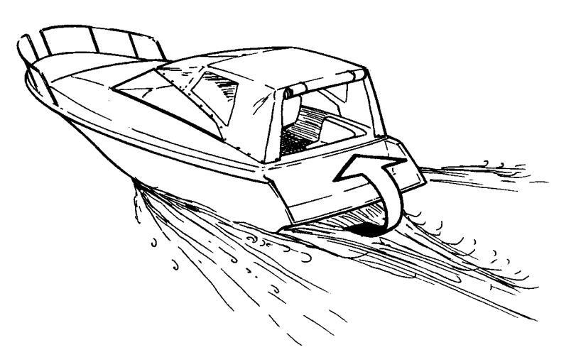
When a boat moves forward through the water a vacuum is created behind it to a greater or lesser extent. In some circumstances this vacuum effect can be so great that the boat's own exhaust gases are sucked into its cockpit or cabin. This poses a risk of carbon monoxide poisoning to those on-board.
This problem is greatest for high, wide beamed boats with a vertical stern. However, it can be a problem for other types of boat in certain conditions (running with the cover up for example). Other factors that exacer-
bate the problem are wind conditions, load distribution, sea conditions, trim, open hatches and ventilators etc.
Most modern boats are designed so that vacuum effect problems are very rare. If a vacuum forms behind the boat do not open ventilators or hatches at the front of the boat. Strangely enough this leads to an increase in the vacuum effect. Instead, try changing speed, trim or load distribution. Try also to take down, open or in some other way change the configuration of the cover. Contact your boat dealer to find a solution for your particular boat.
- Safety equipment: Life jackets for everybody on board, communication equipment, distress flares, approved fire extinguishers, life-buoys, anchors, paddles, torches etc.
- Replacement parts and tools: impeller, fuel filter, fuses, tape, hose clamps, engine oil, propeller and the tools for jobs that may be necessary.
- Get out up-to-date charts for the planned route. Calculate distance and fuel consumption. Listen to weather reports.
- Tell friends or relatives about your planned route when undertaking longer journeys. Remember to tell people about changes to your plans.
- Teach those on-board the location of safety equipment and how to use it. Ensure that there is more than one person on-board who can start and drive the boat safely.
This list should be added to if the type of boat requires extra safety equipment. We recommend that you contact your local boating organization to find a suitable course.
Safety precautions for maintenance and service
▲ Preparations
Knowledge base
The Instruction Manual contains instructions on how to carry out the commonest maintenance and service operations safely and correctly. Read them carefully before starting work.
Service literature for more extensive work can be obtained from your Volvo Penta dealer.
Never undertake an operation if you are not completely sure how to do it. Contact your Volvo Penta dealer for assistance instead.
Stopping the engine
Stop the engine before the engine compartment cover is opened or removed. Unless otherwise specified all maintenance and service must be carried out with the engine stopped.
Immobilize the engine by removing the ignition key, turning off the power supply with the main switch and locking it in the OFF position. Fix a warning that work is being undertaken to the control position.
Approaching a running engine is dangerous. Loose clothing, long hair, fingers or tools can get caught in rotating parts and cause serious personal injury. Volvo Penta recommend that all servicing with the engine running be undertaken by an authorized Volvo Penta workshop.
Lifting out the engine
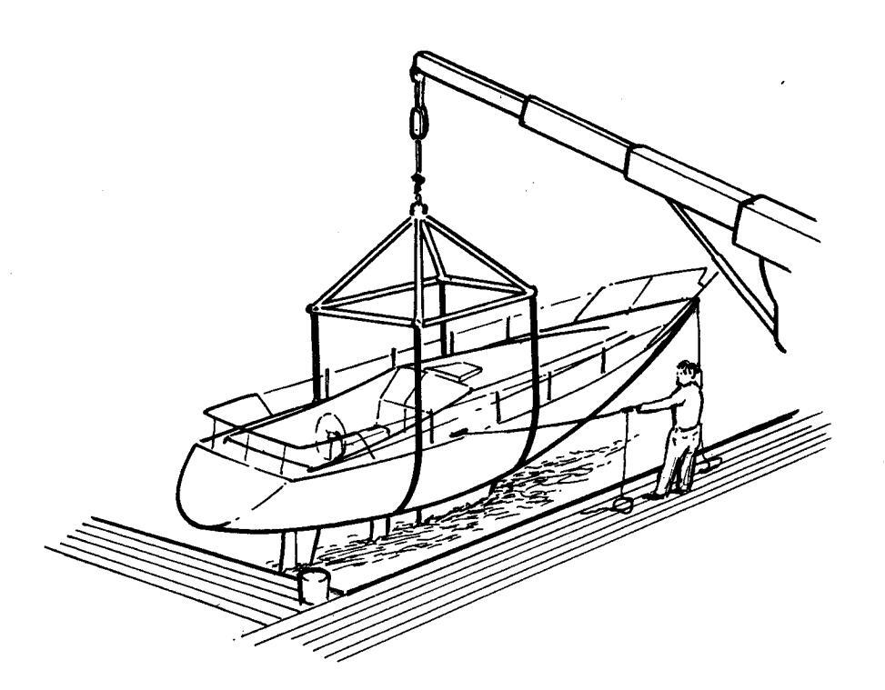
Use the lifting eyes mounted on the engine/reverse gear when lifting the drive unit. Always check that lifting equipment is in good condition and has sufficient load capacity to lift the engine (engine weight including reverse gear and any extra equipment installed). For safety reasons the engine should be lifted with an adjustable lifting beam. All chains and cables should run parallel to each other and as perpendicular as possible to the top of the engine. Note that extra equipment mounted on the engine can change its center of gravity. Special hoists may be necessary to balance the engine and make handling it safe. Never carry out work on an engine suspended on a hoist.
Before starting the engine
Reinstall all protective components that have been removed before starting the engine. Check that no tools or other objects have been left on the engine.
Never start a turbocharger engine without installing the air cleaner (ACL). The rotating compressor in the turbocharger (TC) can cause serious personal injury. Foreign objects may be sucked into it causing mechanical damage.
▲ Fire and explosion
Fuel and lubricating oil
All fuels, most lubricating oils and many chemicals pose a fire hazard. Read and follow the instructions on packaging.
Work on the fuel injection system must be carried out on a cold engine. A fuel leak or spill onto a hot surface or an electrical component can cause a fire.
Store oil and fuel soaked rags and other flammable material in fireproof conditions. In certain circumstances oil soaked rags can spontaneously combust.
Never smoke when refueling, changing the oil or close to filling stations or in the engine compartment.
Non-original components
The components in the fuel injection system, ignition system (petrol engines) and electrical system in Volvo Penta products are designed and manufactured to minimize the risk of fire and explosion.
Using non-original Volvo Penta parts which do not meet the above standards, can result in fire or explosion on board.
Batteries
Batteries contain and produce oxyhydrogen, especially when they are being charged. This gas is easily ignited and highly volatile.
Never allow a naked flame or sparks near the batteries or battery compartment.
Incorrect connection of a battery lead or jump lead can cause a spark which is sufficient to cause the battery to explode.
Start spray
Never use start spray or similar agents to start an engine with pre-heating (glow plugs/start element). The starter element may cause an explosion in the intake manifold. Danger of personal injury.
▲ Hot surfaces and liquids
When the engine is at operating temperature there is always a danger of burns. Avoid hot surfaces. For example: exhaust manifold, turbocharger (TC), oil sump, start element, hot coolant and hot lubricating oil in pipes and hoses.
▲ Carbon monoxide poisoning
Only start the engine in a well-ventilated area. If operating the engine in an enclosed space, ensure that exhaust gases and crankcase emissions are ventilated out of the working area.
Most chemicals such as glycol, rustproofing agents, inhibiting oils and degreasing agents are hazardous to health. Read and follow the instructions on packaging.
Certain chemicals such as inhibiting oils are inflammable and also hazardous to health if inhaled. Ensure that ventilation in the workplace is good and use a protective mask when spraying. Read and follow the instructions on packaging.
Store chemicals and other hazardous material away from children. Deposit excess or used chemicals at a properly designated disposal site.
There is a risk of water penetration when working on the seawater system. Turn off the engine and close the sea cock before starting work on the system.
Avoid opening the coolant filler cap when the engine is hot. Steam or hot coolant can spray out and cause burns.
If work must be carried out with the engine at operating temperature and the coolant filler cap or a cock open or a coolant hose disconnected, open the coolant filler cap carefully and slowly to release pressure before removing the cap completely. Note that the coolant may still be hot and can cause burns.
▲ Lubrication system
Hot oil can cause burns. Avoid skin contact with hot oil. Ensure that the lubrication system is not under pressure before commencing work on it. Never start or operate the engine with the oil filler cap removed, otherwise oil could be ejected.
Always use protective gloves when tracing leaks. Liquids ejected under pressure can penetrate body tissue and cause serious injury. There is a danger of blood poisoning.
Always cover the generator if it is located under the fuel filter. The generator can be damaged by spilled fuel.
▲ Electrical system
Cutting off power
Always stop the engine and break the current using the main switches before working on the electrical system. Isolate shore current to the engine block heater, battery charger, or accessories mounted on the engine.
Batteries
The batteries contain an extremely corrosive electrolyte. Protect your skin and clothes when charging or handling batteries. Always use protective goggles and gloves.
If battery electrolyte comes into contact with unprotected skin wash off immediately using plenty of water and soap. If battery acid comes into contact with the eyes, flush immediately with plenty of water and obtain medical assistance without delay.
Introduction
This Instruction Manual has been compiled to help you get the most from your Volvo Penta engine. It contains all the information you need in order to operate and maintain your engine safely and correctly. Please read the Instruction Manual carefully and learn how to operate the engine, controls and other equipment safely.
Always have the Instruction Manual available. Keep it in a safe place and do not forget to give it to the new owner if you sell your boat.
Responsibility for the environment
We all want to live in a clean environment. Where we can breathe clean air, see healthy trees, have clean water in our lakes and oceans and enjoy the sunshine without worrying about our health. Unfortunately this is no longer something we can take for granted, we must work hard together for the environment.
As a manufacturer of marine engines Volvo Penta has a particular responsibility. This is why concern for the environment is one of the cornerstones of our product development. Today great advances have been made in reducing exhaust emissions, fuel consumption and engine noise in Volvo Penta's wide range of engines.
We hope that you will take care to maintain these properties. Always follow the advice in the Instruction Manual about fuel grades, operation and maintenance and you will avoid unnecessary negative impact on the environment. If you notice changes such as increased fuel consumption or exhaust smoke, please contact your Volvo Penta dealer.
Adapt speed and distance so that swell and noise generated by the boat do not disturb or harm wildlife, moored boats, landing stages etc. Leave islands and harbors in the same condition you would like to find them. Always dispose of environmentally harmful waste such as engine and transmission oil, coolant, old paint, degreasing agents, cleaning residue and old batteries at proper disposal areas.
Together we can work to make a valuable improvement to the environment.
Running-in
The engine must be run in for its first 10 operating hours as follows: Operate the engine normally. Do not operate it at full load except for short periods. Never run the engine at a constant engine speed for long periods during the running-in period.
The engine can be expected to use more engine oil during the running-in period than would otherwise be normal. Check the oil level more often than is normally recommended.
A First Service Inspection must be carried out after 20–50 running hours. For further information: See the Warranty and Service Book.
Fuel and oils
Only use the fuel and oils recommended in the chapter Technical Data. Other grades of fuel and oil can cause operating problems, increased fuel consumption and, in the long-term, a shorter engine service life.
Always change oil, oil filters and fuel filters at the recommended intervals.
Service and replacement parts
Volvo Penta engines and are designed for maximum service life and reliability. They are built to survive in a tough marine environment, but also to cause as little environmental impact as possible. Regular service and the use of Volvo Penta Genuine parts will maintain these properties.
Volvo Penta have built up a world wide network of authorized dealers. They specialize in Volvo Penta products and can help you to maintain your engine in top condition. They have the accessories, genuine replacement parts, test equipment and special tools necessary to provide high-quality service and repair work.
Always follow the maintenance intervals contained in the Instruction Manual. Remember to state the engine/transmission identification number when ordering service and replacement parts.
Certified engines
If you own an engine certificated for Lake Constance and Switzerland or for any other area where exhaust emissions are regulated by law, the following is important:
In some countries and regions environmental legislation requires that the engines in use there be certified.
Certification means that an engine type is tested and approved by the authorities, and that the engine manufacturer guarantees that all engines of that type manufactured thereafter, correspond to the certified engine. The manufacturer is also responsible for ensuring that all engines of that type in operation fulfill
the statutory environmental regulations. This places special requirements on maintenance, service and replacement parts as follows:
- The maintenance and service intervals recommended by Volvo Penta must be observed.
- Only Volvo Penta genuine replacement parts, intended for the certificated engine, may be used.
- The servicing of ignition, timing and fuel injection systems (gasoline) or injector pumps, pump settings and injectors (diesel) must always be carried out be an authorized Volvo Penta workshop.
- The engine must not be modified in any way apart from with accessories and service kits developed for it by Volvo Penta.
- No modifications to the exhaust pipes and air supply ducts for the engine room (ventilation ducts) may be undertaken as this may effect exhaust emissions.
• Seals may only be broken by authorized personnel.
Otherwise the general instructions contained in the Instruction Manual concerning operation, service and maintenance must be followed. Always contact your Volvo Penta dealer if you are not sure about the operation or maintenance of your engine.
▲ IMPORTANT! Use only Volvo Penta Genuine Parts. Use of non-original AB Volvo Penta spare parts will result in AB Volvo Penta being unable to assume liability for the engine meeting engine certification requirements. Any type of damage and/or costs resulting from the use of non-original Volvo Penta replacement parts for the product will not be covered under any warranty provided by AB Volvo Penta.
Warranty
Your new Volvo Penta marine engine is covered by a limited warranty according to the conditions and instructions contained in the Warranty and Service book.
Note that AB Volvo Penta's liability is limited to that contained in the Warranty and Service Book. Read this book as soon as you take delivery of the engine. It contains important information about warranty cards, service and maintenance which you, the owner, must be aware of, check and carry out. Liability covered in the warranty may otherwise be refused by AB Volvo Penta.
* Contact your Volvo Penta dealer if you have not received a Warranty and Service Book.
Presentation
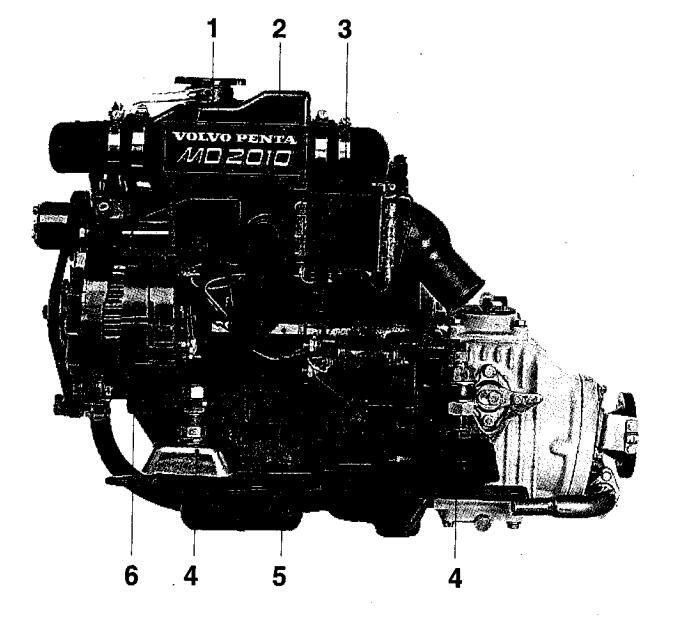
MD2010 with reverse gear MS2L-D
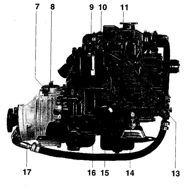
MD2010 with reverse gear MS2L-D
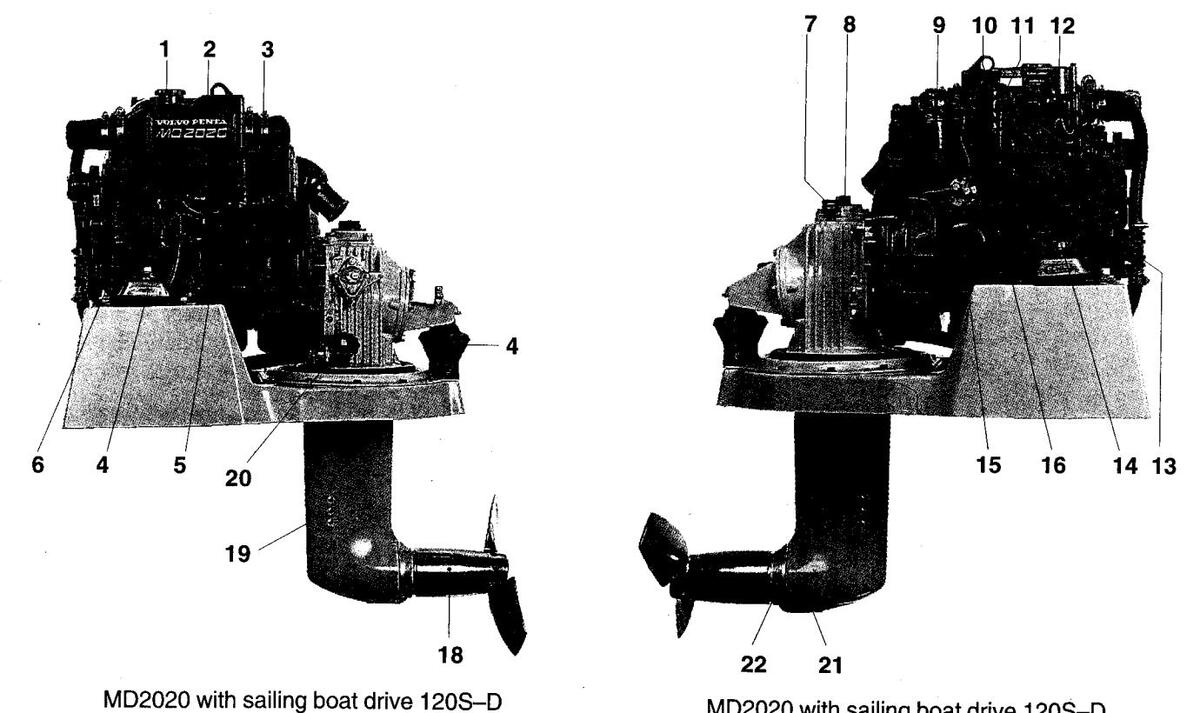
MD2020 with sailing boat drive 120S-D
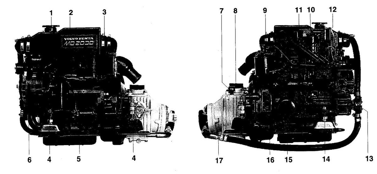
MD2030 with reverse gear MS2A–D
MD2030 with reverse gear MS2A-D
10 11
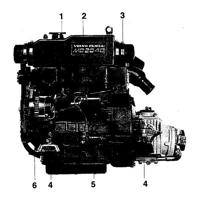
MD2040 with reverse gear MS2L-D
Image: With reverse gear MS2L-D
- 1. Coolant filler cap
- 2. Expansion tank
- 3. Relay box with fuses
- 4. Flexible mounting
- 5. Starter motor
- 6. AC generator
- 7. Dipstick, reverse gear/S-drive
- 8. Oil filler cap, reverse gear/S-drive
- 9. Fine fuel filters
- 10. Oil filler cap, engine
- 11. Dipstick, engine
- 12. Air cleaner (ACL)/Air intake
- 13. Seawater pump
- 14. Injection pump
- 15. Lubricating oil filter
- 16. Fuel pump
- 17. Oil cooler, reverse gear
- 18. Folding propeller
- 19. Cooling water intake, S-drive
- 20. Sea cock, S-drive
- 21. Oil drain plug, S-drive
- 22. Sacrificial anode
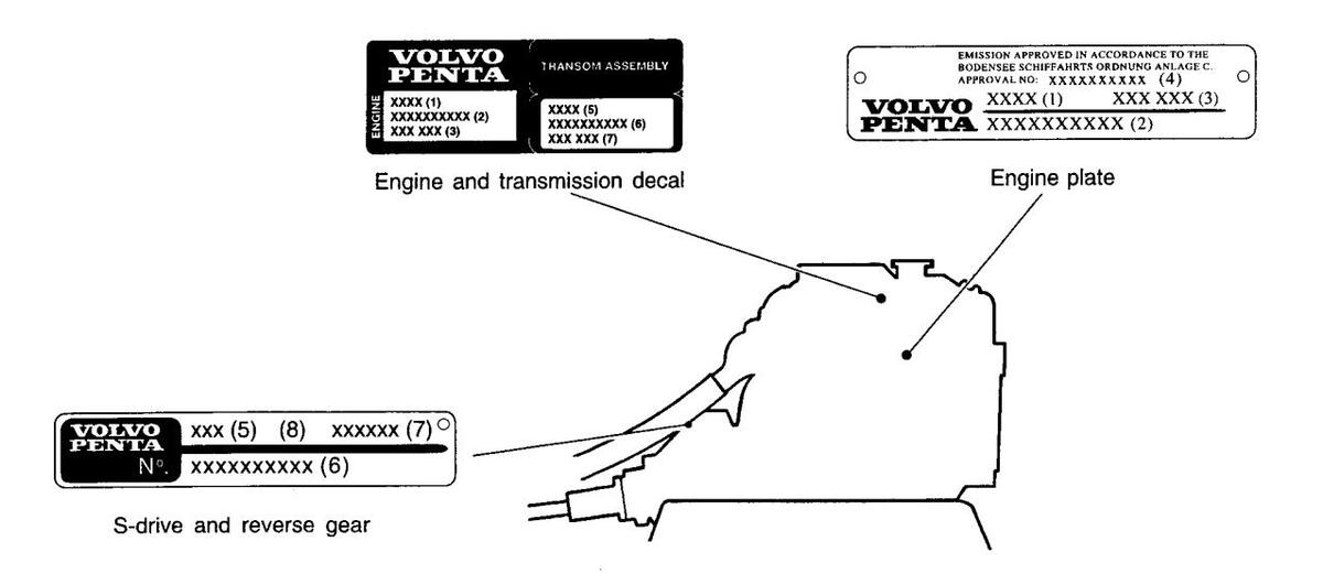
Identification number
Your engine and transmission has identification plates with identification numbers. This information should always be quoted when ordering service and replacement parts. There are probably similar plates on your boat and its equipment. Make a note of the details below, make a copy of the page and keep it so that you have a copy should the boat be stolen.
The appearance and location of identification plates is shown below. The figures in brackets refer to the location of the identification numbers on the identification plate.
Engine
Kev code
persons
| Product designation (1) |
|---|
| Serial number (2) |
| Product number (3) |
| Certification number (4) |
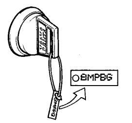
The key code is on a disc secured to the ignition keys. This code is used when ordering extra keys and should not be available to unauthorized
|
SION APPROVED IN
ENSEE SCHIFFAHRT ROVAL NO: XXXX |
ACCORDANCE TO THE
IS ORDNUNG ANLAGE C. LXXXXXXX (4) |
0 | |
|---|---|---|---|
| VOLVO | XXXX (1) | XXX XXX (3) | |
| PENTĂ | XXXXXXX | XXX (2) | |
| Engine pl | ate |
|
VOLVO
PENTA |
TRANSOM ASSEMBLY |
|---|---|
| 뿐 XXXX (1) | XXXX (5) |
| XXXXXXXXXXXX (2) | XXXXXXXXXXX (6) |
| XXX XXX (3) | XXX XXX (7) |
Engine and transmission decal
S-drive/Reverse gear:
| Product designation (5) |
|---|
| Serial number (6) |
| Product number (7) |
| Gear ratio (8) |
| Propeller designation |
| VOLVO | xxx (5) | (8) | xxxxxx (7) े |
|---|---|---|---|
| N°. | XXXXXX | xxxx | (6) |
S-drive and reverse gear
Location of identification plates:
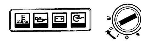
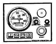
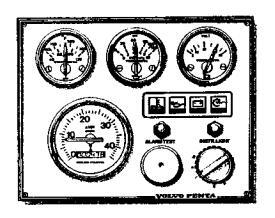
Instrumentation
This chapter only describes the instrument panels available as standard for your engine from Volvo Penta. Note that in certain boats instruments, alarm panels, key switches etc. may be installed separately without the instrument panels shown here.
If you want to install additional instrumentation, or your boat is equipped with instruments not described here, please contact your Volvo Penta dealer.
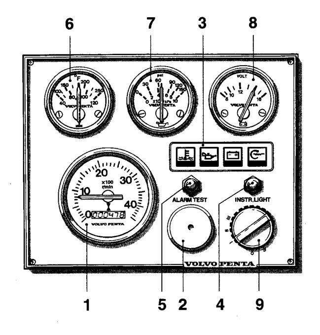

- 1. Tachometer and hour counter (accessory). Displays engine speed. Multiply this value by 100 for revolutions per minute. The hour counter displays engine operating time in hours and tenths of an hour.
- 2. Siren for acoustic alarm.
- 3. Warning display. See 16-19.
- 4. Switch for instrument lighting.
- 5. Alarm test/acknowledgment switch.
To test alarm : Press the switch. All warning lights light and the acoustic alarm sounds.
Alarm acknowledgment: Press the switch if there is an alarm. The acoustic alarm stops but the relevant warning lamp continues to flash until the malfunction is corrected.
- 6. Temperature gauge. Displays the engine coolant temperature.
- 7. Oil pressure gauge. Displays the oil pressure in the engine.
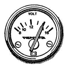
- 8. Voltmeter. Displays the charge voltage from the generator.
- 9. Ignition switch. See description in the next section.
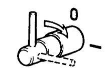
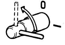
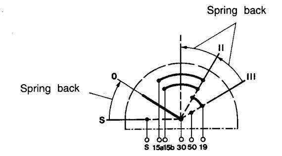
Ignition switch
The starter keys are tagged with a key code. This code must be quoted when ordering extra keys. Keep the code where it is not available to unauthorized persons.

- S = The mechanical restart inhibitor is disengaged. The key springs back automatically to the 0 position.
- 0 = The key can be inserted and removed.
- I = Operating position.
- II = Glow plug position. The glow plugs are connected and pre-heating the engine.
- III = Starting position. The starter motor is engaged.
- IMPORTANT! Read the starting instructions in the chapter: Starting the engine.
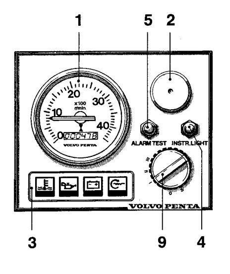
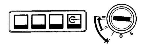
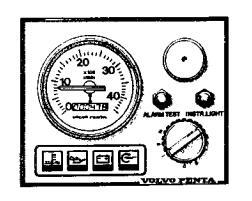
Instrument panel without ignition switch
The instrument panel does not have an ignition switch. To stop unauthorized persons starting the engine the wheelhouse should have a lock or a lockable main switch should be used.
()
()
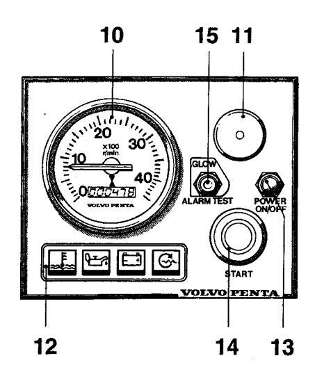
- 10. Tachometer and hour counter (accessory). Displays engine speed. Multiply this value by 100 for revolutions per minute. The hour counter displays engine operating time in hours and tenths of an hour.
- 11. Siren for acoustic alarm.'
- 12. Warning display. See 16-19.
- 13. Switch for connecting and disconnecting instrument panel.
- 14. Starter button. The starter motor is engaged when this button is pressed.
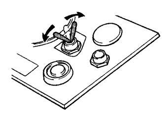
- 15. Alarm test/acknowledgment and glow plug rocker switch.
Glow plugs active: When the rocker switch is in the up position the glow plugs are activated.
To test alarm: Move the rocker switch down. All warning lights light and the acoustic alarm sounds.
Alarm acknowledgement: If there is an alarm the rocker switch is moved down and the alarm is acknowledged. The acoustic alarm stops but the relevant warning lamp continues to flash until the malfunction is corrected.
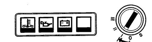
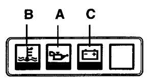
Warning display
If the acoustic alarm sounds, one of the three warning lamps (16-18) on the instrument panel starts to flash to indicate the source of the alarm.
16. Engine coolant temperature too high.
- IMPORTANT! If the alarm sounds: Reduce engine speed to idle (neutral). Stop the engine if the temperature does not drop. Investigate and correct the malfunction.
- 17. Low oil pressure.
IMPORTANT! If the alarm sounds: Stop the engine immediately and investigate.
- 18. Generator not charging.
- 19. Indicator lamp Comes on when the glow plugs are activated.
Check that the warning lamps are operating before starting the engine according to the description of the relevant instrument panel.
17 18
19
16
0
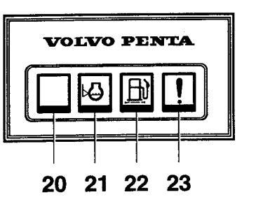
Extra warning display
If the acoustic alarm sounds, one of the four warning lamps starts to flash to indicate the source of the alarm. The extra warning display is an accessory.
20. Not used.
- 21. Low coolant level. Top up to correct level before starting.
- 22. Water in extra fuel pre-filter. Drain off water in filter. See instructions in the chapter Maintenance.
- 23. Extra alarm for an optional function.
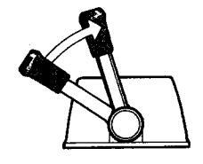
Controls
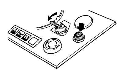
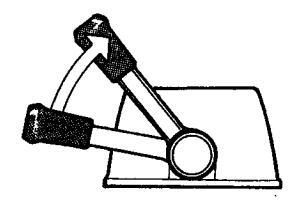
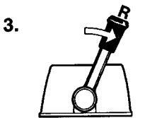
The shift function and engine speed control are combined in one lever. If necessary the shift function can be easily disengaged so that only the engine speed (rpm) is affected by the lever. The control lever has an adjustable friction brake. A neutral position switch is available as an accessory, this will only permit the engine to be started with the drive/reverse gear disengaged.
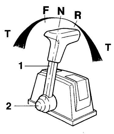
Control lever for tip mounting
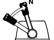
Maneuvering
Shifting and engine speed are controlled with the same lever (1).
- N = Neutral position. Drive/reverse gear disengaged.
- F = Drive/reverse gear engaged for movement ahead.
- R = Drive/reverse gear engaged for movement astern.
- T = Engine speed control
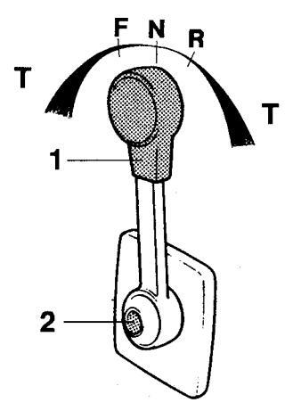
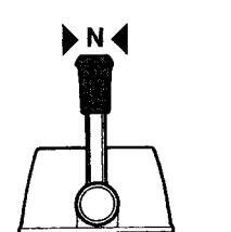
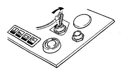
Control lever for side mounting
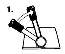
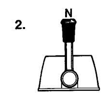
Disengaging the shift function
Move lever (1) to the neutral position (N). Press in button (2), move the lever slightly forward and release the button. The shift function is now disengaged and the lever affects only engine speed.
When the lever is moved back to the neutral position it will automatically re-engage.

M IMPORTANT! Take care not to engage the drive/reverse gear by mistake.
1
()
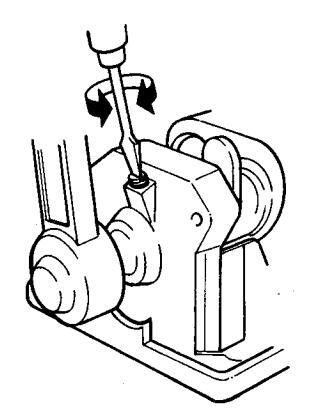
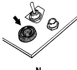
Adjusting the friction brake
The friction brake only affects the engine speed control movements
- Lift the cover over the control. For side-mounted controls the lever must first be removed.
- Set the lever to the half-open throttle/reverse position.
- Adjust the friction brake. Turning the screw clockwise (+) makes the lever movement stiffer, while turning counterclockwise (-) makes it easier to move the lever.
- Beinstall the cover and lever
Starting the engine
Make a habit of checking the engine and engine compartment visually before operating the boat. This will help you to quickly detect anything unusual that has or is about to happen. Also check that instruments and the warning display are indicating normal values when you have started the engine.
Before starting
- Open the cooling water intake sea cock.
- Open fuel cock.
- Check that there are no fuel, engine coolant or oil leaks.
- Check oil and engine coolant levels in the engine. See chapter: Maintenance.
- Switch on the main switch.
M IMPORTANT! Never break the circuit with the main switch while the engine is running. This could damage the generator.
- Start the engine compartment fan if one is fitted and let it run for at least four minutes.
- Check that there is sufficient fuel.
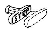
- Push in the stop control.
Starting. Instrument panel with ignition switch
- WARNING! Never use start spray or similar to start the engine. Danger of explosion!
- 1. Move the control lever to the neutral/idle position.
- 2. Insert the key in the ignition switch. Turn key to the "I" position. The three warning lamps come on and can be checked.
Check that the acoustic alarm is operating by pressing the "Alarm Test" button.
3. Turn key to the "II " position. The indicator light comes on and the glow plugs are connected to pre-heat the engine. Let the glow plugs remain activated for 10 seconds (max. 30 seconds).
IMPORTANT! Always pre-heat the engine (even when it is at operating temperature).
4. Turn the key to position "III" to start. Release the key as soon as the engine has started, the key will automatically spring back to the "I" position. If the engine did not start the key must first be turned to the "0" position before trying again.
▲ IMPORTANT! If the starter motor is engaged for its maximum engagement time (20–30 seconds) let it cool down for five minutes before trying to start the engine again.
5. Warm up the engine at low speed and low load.
IMPORTANT! Do not race the engine while it is cold.
Starting. Instrument panel without ignition switch
WARNING! Never use start spray or similar to start the engine. Danger of explosion!
1. Move the control lever to the neutral/idle position.
2. Activate the instrument panel by pressing the "Power ON/OFF" switch. The three warning lamps come on and can be checked.
Check that the acoustic alarm is operating by pushing the rocker switch to the "Alarm Test" position.
3. Push the rocker switch to the "Glow" position. The indicator light comes on and the glow plugs are connected to pre-heat the engine. Let the glow plugs remain activated for 10 seconds (max. 30 seconds).
IMPORTANT! Always pre-heat the engine (even when it is at operating temperature).
-
4. Press the starter button. Release the starter button as soon as the engine starts.
- IMPORTANT! If the starter motor is engaged for its maximum engagement time (20–30 seconds) let it cool down for five minutes before trying to start the engine again.
- 5. Warm up the engine at low speed and low load.

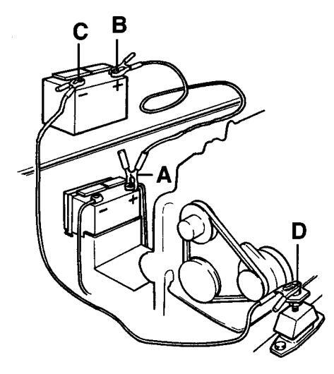
Starting using auxiliary batteries
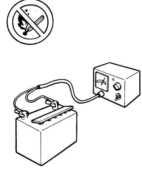
WARNING! Batteries produce oxyhydrogen. This gas is easily ignited and highly volatile. A short-circuit, naked flame or spark can cause a large explosion. Ensure that the ventilation is good.
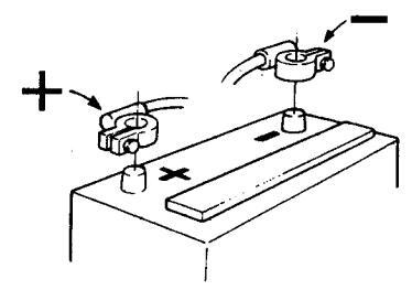
Never mix up battery positive and negative terminals. This may cause sparks and an explosion.
- 1. Check the auxiliary batteries have the same rated voltage as the engine's system voltage.
- 2. First connect the red jump lead to the discharged battery's + terminal (A) and then to the auxiliary battery's + terminal (B).
- First connect the black jump lead to the auxiliary battery's terminal (C) and then to a site (D) where there is good contact with the cylinder block as far away from the discharged battery as possible.
- 4. Start the engine and run it at a fast idle for approximately ten minutes to charge the battery.
- WARNING! Approaching a running engine is dangerous. Watch out for rotating components and hot surfaces.
Do not touch the connections while trying to start the engine: This may cause sparks. Do not lean over the batteries.
5. Stop the engine. Remove the jump leads in exactly the opposite order to which you put them on.
Operation
Avoid violent and unexpected changes in course and gear engagement. There is a risk that someone aboard will fall over or overboard.
MARNING! A rotating propeller can cause serious injury. Check that nobody is in the water before engaging ahead or astern. Never drive near bathers or in areas where people could be in the water.
Checking instruments
Check the instruments and warning display directly after starting the engine and then at regular intervals while driving the boat. Stop the engine if there is an abnormal reading or any warning lamp comes on and the alarm sounds. For engines with measuring instruments the following standard values apply:
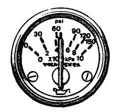
Oil pressure (A)
Normal operating oil pressure is between 150–500 kPa (21–71 psi). At engine idle this is normally lower. The acoustic alarm will automatically go off if the oil pressure is too low.
IMPORTANT! If the alarm sounds: Stop the engine immediately. Investigate and correct the malfunction.
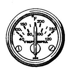
Engine coolant temperature (ECT) (B)
Normal operating temperature is between 75–90°C. The acoustic alarm will automatically go off if the engine coolant temperature (ECT) is too high.
IMPORTANT! If the alarm sounds: Reduce engine speed to idle (neutral). Stop the engine if the temperature does not drop. Investigate and correct the malfunction.
Charging (C)
The operating charge current is approx. 14 V. When the engine is stopped battery voltage is approx. 12 V.
Cruising speed
Operating the engine at wide open throttle (WOT) should be avoided since it is both uneconomical and uncomfortable. Volvo Penta recommends a cruising speed in the range 300–500 rpm lower than maximum rpm at WOT. Depending on hull type, choice of propeller, load and conditions etc. the maximum engine speed at top speed can vary, but it should be within the WOT range.
Wide Open Throttle (WOT) range:
MD2010-2040 ...... 3,200–3,600 rpm
Maneuvering
All shifting between ahead and astern must be done at engine idle speed. Shifting at higher speeds may damage the drive or reverse gear and will also be uncomfortable for those on board.
- 1. Reduce engine speed to idling and, if possible, let the boat lose most of its speed.
- 2. Move the reverse gear control lever quickly and firmly into the neutral position. Wait for a moment.
- 3. Move the gear control lever quickly and firmly into astern, then increase the speed.
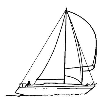
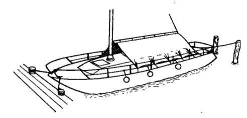
When sailing
If the boat has a fixed propeller the control lever must be in the neutral position when sailing. If the boat has a folding propeller the control lever must be in the astern position.
IMPORTANT! If you are sailing far, run the engine every 10 hours if the boat has a fixed propeller. This is to ensure the drive/reverse gear is lubricated and cooled. If this is not possible then a propeller shaft brake must be installed.
Stopping the engine
The engine should be run for a few minutes at idle (in neutral) before turning it off. This will avoid boiling and even out the temperature. This is especially important if the engine has been operated at high engine speeds and loads.
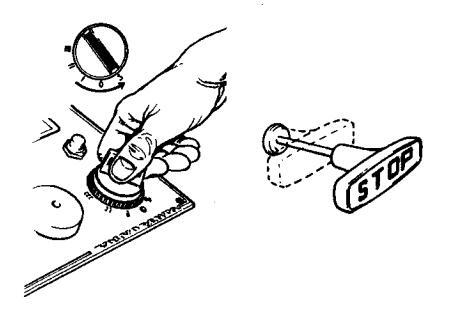
Stopping
Pull and hold out the stop control until the engine has stopped. Push in the stop control. Turn the key to stop position "S" . The key will automatically spring back to the "0" position when it is released and can then be removed.
After stopping the engine
- Inspect the engine and engine compartment for any leaks.
- Close the fuel cock and sea cock for the cooling water intake.
IMPORTANT! Do not forget to open the cocks before the engine is started again.
- Switch off the main switch if the boat is not to be used for some time.
- IMPORTANT! Never break the circuit with the main switches while the engine is running. This could damage the generator.
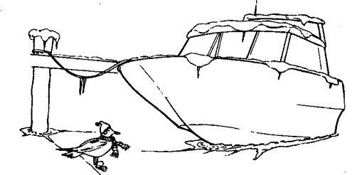
Laying up
If the boat is not going to be used for some time but is being left in the water, the engine must be run to operating temperature at least once every 14 days. This prevents the corrosion in the engine. If the boat will not be used for more than two months then inhibiting should be carried out: See chapter on Laying up/Launching.
Cold weather precautions
To prevent freezing damage, the seawater system must be drained and the freshwater system coolant must have sufficient antifreeze protection. See chapter Maintenance "Cooling systems".
MPORTANT! A poorly charged battery may burst as a result of freezing.
Maintenance schedule
Your Volvo Penta engine and its transmission is designed for maximum service life and reliability. They are built to survive in a tough marine environment, but also to cause as little environmental impact as possible. Regular maintenance according to the following schedule is necessary if the engine and transmission are to operate without problems.
MARNING! Read the chapter on Maintenance carefully before starting work. It contains instructions on how to carry out the most common maintenance and service operations safely and correctly.
▲ IMPORTANT! Service operations marked □ must be carried out by an authorized Volvo Penta Service workshop.
First Service inspection:
□ A first Service Inspection must be carried out in accordance with the instructions in the Warranty and Service Book.
Daily before starting first time:
- Engine oil. Checking level
- Coolant. Checking level
Every 14 days:
- Fuel pre-filter. Drain water
- Drive belt. Check
- Seawater filter. Clean
- Battery. Check electrolyte level
- Reverse gear. Check oil level
- S-drive. Check oil level
Every 100 operating hours or at least once a year:
- Engine oil. Change
- Oil filter. Replace
Every 200 operating hours or at least once a year:
- Fuel filter. Replace
- Fuel pre-filter. Replace
- Idling speed. Check
- Coolant1). Change
- Seawater pump. Check impeller
- Vacuum valve. Clean
- Reverse gear. Oil changel
- Reverse gear. Lubricate propeller shaft seal.
- S-drive. Oil change
- S-drive. Checking corrosion protection
- S-drive. Check rubber seal (hull/drive)
Every 400 operating hours or at least once every two years:
- Air Cleaner (ACL). Clean
- Coolant1). Change
- Heat exchanger. Clean
- Injectors. Test pressure
- □ Valve clearance. Adjustment
Every four years:
• Folding propeller. Replace tab washer and locking screw.
Every 500 operating hours or at least every fifth year:
□ Reverse gear. Replacing propeller shaft seal
Every seven years:
S-drive. Replacing rubber seal between drive and hull
1) If the freshwater system is filled with an anti-corrosion agent mixture it must be changed every year. If the freshwater system is filled with an antifreeze (glycol) mixture it must be changed every other year.
Maintenance
This chapter describes how to carry out the above maintenance. Read the instructions carefully before starting work. Maintenance intervals are contained in the chapter above. Maintenance schedule
WARNING! Read the safety precautions for maintenance and service in the chapter: Safety Precautions, before starting work.
WARNING! Unless otherwise specified all maintenance and service must be carried out with the engine stopped. Stop the engine before the engine compartment cover is opened or removed. Immobilize the engine by removing the ignition key, turning off the power supply with the main switch and locking it in the OFF position.
Engine, general
Air Cleaner (ACL)*. Cleaning
Remove air cleaner (ACL). Carefully blow clean using compressed air. Take care that no contaminants enter the engine.
* Applies to the 2040 and later versions of the 2020 and 2030.
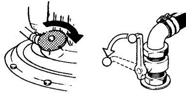
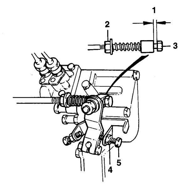
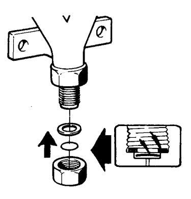
Idling. Adjustment
Idling speed should be 850 ± 25 rpm. A lower idling speed can cause the engine to stall and a higher speed increases the stresses on the drive/reverse gear when shifting.
Adjust with the engine at operating temperature as follows:
-
1* Set the control lever in the neutral position. Check that gap (1) is approx. 3 mm. Adjustment: Slacken off the locknut (2) and adjust until the correct gap is obtained with screw (3). Tighten locknut.
- This point does not apply to boats with double control positions.
- 2 Start engine and allow to idle with gear selector in neutral.
- WARNING! Approaching a running engine is dangerous. Watch out for rotating components and hot surfaces.
- 3 Slacken off locknut (4). Adjust engine speed with adjustment screw (5). Tighten locknut. Repeat step 1.
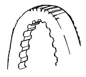
Drive belt. Check
The belt drives both the circulation pump and the generator. A belt that is too loose can result in slippage, poor cooling and poor charging. A belt that is too tight can damage the bearings in the circulation pump and damage the generator.
Check the tension of the belt regularly. Adjust if necessary. Check that the belt is not cracked or damaged. Replace a worn belt. Keep a spare belt onboard.
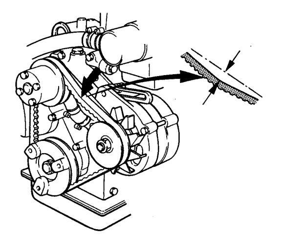
MD2010, MD2020
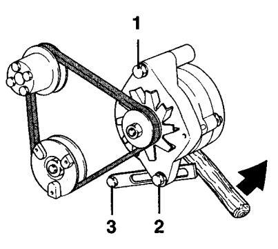
MD2030, MD2040
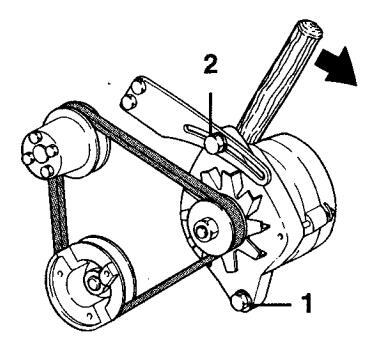
Drive belt. Adjusting and replacing
WARNING! Always turn the engine off before starting maintenance work.
/ IMPORTANT! Tighten screw (1) to 50–60 Nm.
Adjusting
Check and adjust as necessary after operating the engine when the belts are warm.
It should be possible to depress a correctly tensioned belt approx. 10 mm between the pulleys with your thumb. To adjust slacken off screws (1 and 2) and if necessary screw (3) on the 2010 and 2020. Tension belt, adjust tension and tighten screws. Check the tension.
Replacing
To replace the belt slacken off screws (1 and 2) and if necessary screw (3) on the 2010 and 2020. Press the generator in towards the cylinder block so that the belt can be removed. Clean off the pulley grooves. Install the new belt. Adjust as above. Check belt tension again after a few hours' operation.
Lubrication system

1 IMPORTANT! With a new or reconditioned engine. the oil and oil filters must be changed after 20–50 hours of operation. After that they should be changed every 100 operating hours or at least once a year. Use only the recommended grades of oil: See the chapter "Technical Data".
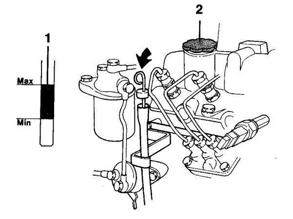
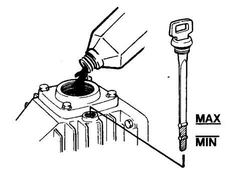
Oil level. Checking and topping up
The oil level should be within the marked area on the dipstick (1). It should be checked every day before the engine is started. Topping up is done through the valve cover (2). Top up oil slowly. Wait a few minutes before checking the oil level again to give the oil time. to run down to the oil pan. Then check the level again. Use only the recommended grades of oil: See the chapter "Technical Data".
MIMPORTANT! Do not fill the oil above the MAX level.
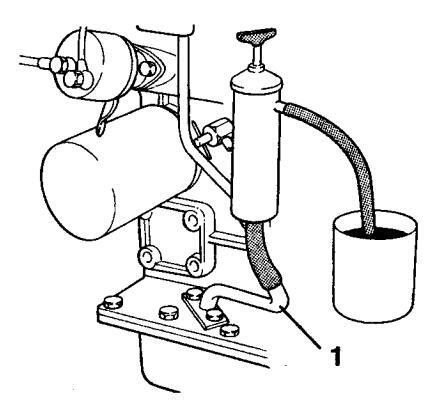
Oil and oil filters. Changing
Run the engine to operating temperature so that the oil is easier to suck out. Stop the engine. Suck out the oil using an oil drain pump through oil drain pipe (1)
WARNING! Hot oil and hot surfaces can cause hurns
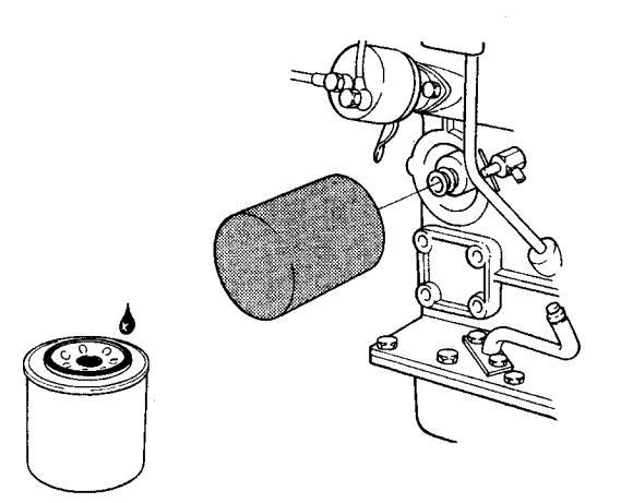
Unscrew the old filter. (To avoid oil spills put a plastic bag over the filter before it is unscrewed). Check that the engine mating surface is clean. Moisten the filter rubber gasket with a little oil. Screw on the new filter by hand until it is in contact with the mating surface. And then a further half turn but no more!
Top up oil to correct level. Start the engine and let it idle. Check that the warning lamp for low oil pressure goes out. Stop the engine. Check the oil level and top up if necessary. Check that there are no leaks round the oil filter
NOTE! Collect up the old oil and filter for deposit at a proper disposal site.
Cooling system
The cooling system is divided into a freshwater and a seawater system. The seawater pump sucks water into the seawater system through the drive/reverse gear. Seawater is then pumped through the heat exchanger and into the exhaust elbow pipe where it is mixed with the exhaust gases. The freshwater system is the internal engine coolant system. It is a closed system driven by the circulation pump. The freshwater system engine coolant is cooled in the heat exchanger by the seawater.
WARNING! Risk for water penetration when working with the cooling system. Close the sea cock.
Coolant, General
The freshwater system must be filled with a coolant that protects the engine against internal corrosion and from freezing (if the climate requires it). Never use freshwater alone.
WARNING! Anti-corrosive agents and antifreeze products are harmful to health (do not drink!)
When there is a risk for freezing the engine coolant system must be filled with a mixture of 50% Volvo Penta antifreeze and 50% clean water. This mixture prevents corrosion and protects against freezing down to approx. -40°C. It should be used all year round. NOTE! There should be at least 40% antifreeze in the system for complete protection against corrosion.
Where there is no risk of damage from freezing the engine coolant can be fresh water with of Volvo Penta anti-corrosion fluid added. Mix according to the instructions on the packaging

MIMPORTANT! Never mix the anti-corrosive agent with antifreeze as this could result in foam generation and greatly reduced cooling properties.
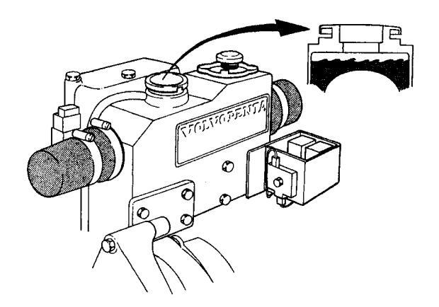
Coolant, Filling
MARNING! Do not open the engine coolant system filler cap when the engine is still hot except in an emergency. Steam or hot coolant may spray out.
Turn the filler cap to the first stop and let any pressure escape from the system before removing the cap. Top up coolant if necessary. The level should be just under the neck of the filler pipe or between the MIN and MAX marks on the separate plastic expansion tank (accessory) if installed. Reinstall the filler cap.
Coolant. Changing
The corrosion-proofing additives become less effective with time and the coolant must be changed. If the freshwater system is filled with antifreeze mixture it must be changed every other year. If the system is filled with anti-corrosion agent mixture it must be changed every year.
Drain the coolant and clean the heat exchanger as follows. Close the drain cock and fill with fresh coolant.
Coolant. Draining
Position a container under the drain cock on the starboard side of the cylinder block. Remove the filler cap on the heat exchanger (this lets the coolant run out faster). Open the drain cock and drain coolant. Clean the heat exchanger as follows before filling coolant.
NOTE! Deposit old coolant at a properly designated disposal site.
Heat exchanger. Cleaning
Cooling performance is reduced by scaling in the heat exchanger. It should therefore be flushed when the coolant is changed.
- 1. Drain the coolant as above.
- 2. Insert a hose into the filler pipe on the heat exchanger. Flush the fresh water until the water which runs out of the drain cocks is clean. Allow all the water to run out.
- 3. Close the drain cock. Fill with new coolant to correct level. Reinstall the filler cap.
Seawater system. Draining
To prevent freezing damage the seawater system must be drained in cold weather where there is a risk of frost.
- WARNING! Risk for water penetration. Close the sea cock if the boat is in the water. If the boat is laid up then the sea cock can be open.
- 1. Drain seawater filter (accessory). Remove the cover and sealing plate on the sea water filter. Disconnect hoses and drain them.
- 2. Remove the cover from the seawater pump and let the water run out.
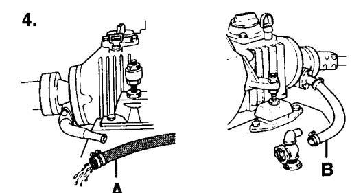
- 3. Engine with drive: Disconnect seawater pump hose by the drive and bend down so that the water runs out.
- Engine with reverse gear Disconnect seawater pump hose (A) by the drive and bend down so that the water runs out. Disconnect hose (B) by the sea cock and empty it of water.
-
5. Connect and tighten all hoses. Reinstall the cover on the seawater pump* and the cover and seal on the seawater filter.
- * When laying up the boat, remove the impeller from the seawater pump and store it in a cool place in a plastic bag. Reinstall the impeller when bringing the boat out of storage.
Impeller. Checking/Replacing
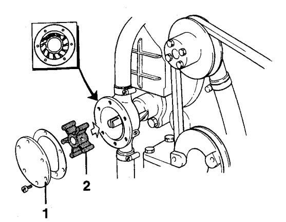
WARNING! Risk for water penetration. Close the sea cock.
Close the sea cock. Remove cover (1) on the seawater pump. Remove impeller (2). If there are cracks or other defects the impeller must be replaced. Lubricate the pump housing and the inside of the cover with a little waterproof grease for rubber. Reinstall the impeller using a clockwise rotating movement. Install the cover together with a new gasket. Open the sea cock.
MPORTANT! Always carry a spare impeller on board.

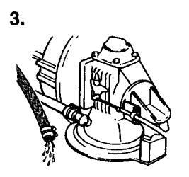
Seawater system. Cleaning and inhibiting
To prevent the build up of deposits and salt crystals in the seawater system it must be flushed with freshwater. When the boat is laid up it must also be inhibited.
- WARNING! There is a risk of water penetration. Cleaning and inhibiting the seawater system should be carried out with the boat on land.
- 1. Open the sea cock.
- 2. Secure a container by the exhaust outlet.
- 3. Disconnect seawater hose (from the sea cock) on the reverse gear or on the seawater pump if the engine has an S-drive.
- 4. Connect a hose* which is long enough to reach the container so that the freshwater can be circulated.
* Internal diameter = 19 mm.
5. Fill the container with freshwater. Check that there is nothing that will get splashed behind the exhaust outlet.
IMPORTANT! The impeller will be damaged if it runs dry.
-
6. Set the gear control lever in the neutral position. Check that nobody is near the propellers. Start engine. Let it run at fast idle a few minutes. Stop the engine.
- WARNING! Approaching a running engine is dangerous. Watch out for rotating components and hot surfaces.
- 7. To inhibit the seawater system repeat points 5 and 6 but replace the freshwater with antifreeze.
- 8. Reconnect the seawater hose
- 9. The system is now inhibited. The antifreeze mixture should be left in the system while the boat is laid up. Drain the mixture just before the boat is launched. Reuse the antifreeze mixture next season or deposit it at a properly designated disposal site.
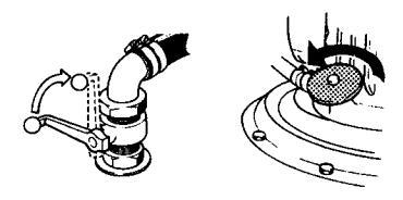
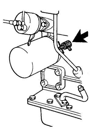
Vacuum valve. Cleaning
Some engines have a vacuum valve installed in the seawater piping.
WARNING! Risk for water penetration. Close the sea cock.
Close the sea cock. Disassemble the valve. Unscrew the hexagonal cover. In the cover there is a membrane and a gasket. Clean all the parts. Turn the cover upside down. Install the membrane first and then the gasket. Turn the valve housing upside down as well. Screw the cover into position, but not too hard (0.2 kpm), or the valve may stop working.
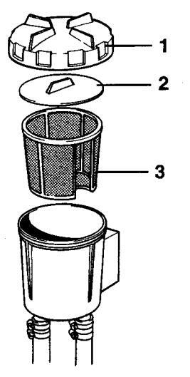
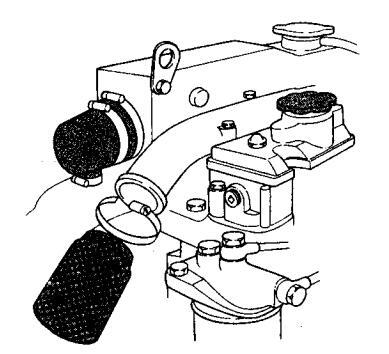
Seawater filter. Cleaning
The seawater filter is an accessory. Screw off cover (1) and remove seal plate (2). Lift out and clean the insert (3).
A IMPORTANT! If the boat is used in water that has a lot of contaminants, seaweed etc. the filter must be checked more frequently than indicated in the maintenance schedule. Otherwise there is a risk the filter will clog and the engine will overheat.
Fuel system
All work on the engine injection pump or injectors must be carried out at an authorized workshop. Use only the recommended grade of fuel: See the chapter "Technical Data".
MARNING! Fire risk. Work on the fuel injection system must be carried out on a cold engine. A fuel spill onto a hot surface or an electrical component can cause a fire. Store fuel soaked rags and other flammable material in fireproof conditions.
Venting the fuel system
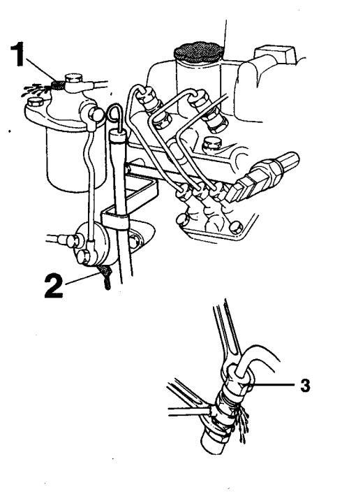
The fuel system must be vented after the fuel filters have been replaced or after refilling the fuel tank after it has been run dry.
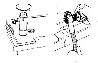
- 1. Open vent screw (1) on the filter mounting approx. three turns. Avoid fuel spillage. Use rags around the venting point.
- 2. Pump the fuel using hand pump (2) until there are no more air bubbles visible in the fuel. Continue pumping and at the same time tighten the venting screw. If the pump effect is poor, turn the engine over slightly so that the pump drive cam changes position.
- 3. Slacken off the injector delivery line nuts and set the engine speed control to wide open throttle (WOT). Turn the engine over at WOT with the starter motor until fuel comes out of the delivery lines. Avoid fuel spillage. Tighten delivery line nuts.
- 4. Start the engine and check for leaks.
- WARNING! Approaching a running engine is dangerous. Watch out for rotating components and hot surfaces.

Fuel filter Replacing
Clean the filter mounting. To avoid fuel spills put a plastic bag over the filter before it is unscrewed. Unscrew the filter. Moisten the rubber filter gasket with a little oil. Screw on the new filter by hand until it is in contact with the mating surface. And then a further half turn but no more! Vent fuel system. Deposit the old filter at a properly designated disposal site.
Start the engine and check for leaks.
WARNING! Approaching a running engine is dangerous. Watch out for rotating components and hot surfaces.
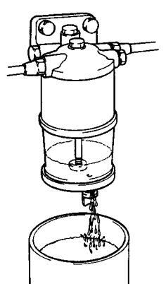
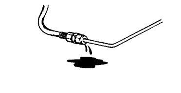
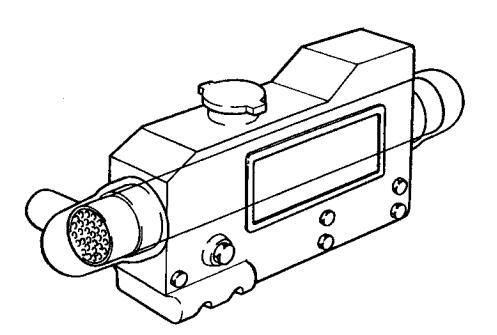
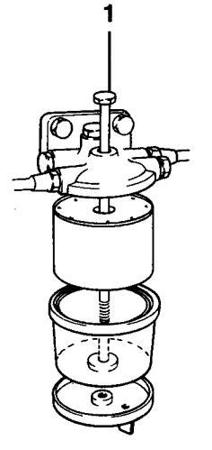
Fuel pre-filter. Draining
The fuel pre-filter is an accessory.
Position a container under the fuel filter. Drain off water and contaminants using the cock/plug at the bottom of the glass.
A IMPORTANT! Wait a few hours after the engine has been turned off before draining the filter.
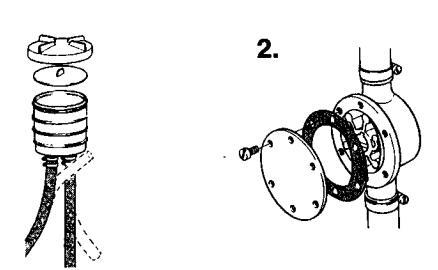
Fuel pre-filter. Replacing filter insert
Close fuel cock at the fuel tank. Position a container under the fuel filter.
Remove the glass by slackening off screw (1). Empty and clean glass. Replace insert and reinstall glass. Open fuel cock. Vent fuel system. Deposit the old filter insert at a properly designated disposal site.
Start the engine and check for leaks.
WARNING! Approaching a running engine is dangerous. Watch out for rotating components and hot surfaces.
Electrical system
MARNING! Always stop the engine and break the current using the main switches before working on the electrical system. Isolate shore current to the engine block heater, battery charger, or accessories mounted on the engine.
Main switch
The main switch must never be turned off before the engine has stopped. If the circuit between the generator and the battery is cut off when the engine is running the generator can be seriously damaged. For the same reason charging circuits must never be switched over while the engine is running.
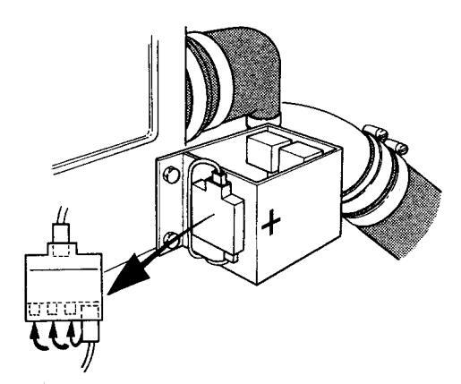
Fuses
The engine has a fuse holder with four 15 A fuses. This is located on the relay box to the left at the rear of the engine. One fuse protects the system and cuts power in the event of an overload, the others are spares.
If a fuse blows the system can be reconnected by moving the cable to the next fuse. Always investigate the cause of an overload before resetting the fuse!
MINPORTANT! Make sure that you always have spare fuses on board.
Electrical connections
Also check that all electrical connections are dry and free of oxidation and that there are no loose connections. If necessary, spray these connections with a water-repellent spray (Volvo Penta Universal oil).
Starting using auxiliary batteries
See instructions for starting the engine with an auxiliary battery in the chapter: Starting the engine.
Battery. Maintenance
- WARNING! Risk of fire and explosion. Never allow an open flame or electric sparks near the battery or batteries.
- MARNING! Never mix up battery positive and negative terminals. This may cause sparks and an explosion.
- WARNING! The battery electrolyte contains extremely corrosive sulfuric acid. Protect your skin and clothes when charging or handling batteries. Always use protective goggles and gloves. If battery electrolyte comes into contact with unprotected skin wash off immediately using plenty of water and soap. If battery acid comes into contact with the eyes, flush immediately with plenty of water and obtain medical assistance without delay.
Connecting and disconnecting
First connect the red battery lead + to the battery + terminal. Then connect the black battery lead – to the battery – terminal.
When disconnecting the battery, disconnect the -lead (black) first and then the + lead (red).
Cleaning
Keep batteries dry and clean. Oxidation or dirt on the battery and battery terminals can cause shortcircuits, voltage drop and discharge especially in damp weather. Clean the battery terminals and leads to remove oxidation using a brass brush. Tighten the cable terminals well and grease them with terminal grease or petroleum jelly.
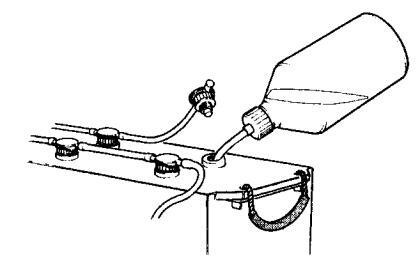
Topping up
The electrolyte should be 5–10 mm over the plates in the battery. Top up using distilled water if necessary. Charge the battery after topping up for at least 30 minutes by running the engine at fast idle. NOTE! Certain maintenance-free batteries have special instructions which must be followed.
Battery. Charging
WARNING! Danger of explosion! The batteries give off hydrogen gas during charging which when mixed with air can form an explosive gas – oxyhydrogen. A short-circuit, naked flame or spark can cause a large explosion. Ensure that the ventilation is good.
▲ WARNING! The battery electrolyte contains extremely corrosive sulfuric acid. Protect your skin and clothes when charging or handling batteries. Always use protective goggles and gloves. If battery electrolyte comes into contact with unprotected skin wash off immediately using plenty of water and soap. If battery acid comes into contact with the eyes, flush immediately with plenty of water and obtain medical assistance without delay.
If the battery has discharged it must be charged. If the boat has not been used for some time charge the battery and then trickle charge it (see manufacturer's recommendations). A poorly charged battery will be damaged and may burst in cold weather.
IMPORTANT! Follow the instructions supplied with the battery charger carefully. To avoid electrolytic corrosion when an external charger is connected, always disconnect the battery leads before connecting the charger.
When charging, unscrew filler plugs but leave them in their holes. Ventilation should be good, particularly if the batteries are being charged in an enclosed area.
WARNING! Always switch off the charging circuit before removing the battery charger connectors. Never mix up battery positive and negative terminals. This may cause sparks and an explosion.
Special instructions apply when boost charging the batteries. Avoid boost charging the batteries as it will shorten their service life.
Electrical installations
Leakage current from the electrical system can be caused by incorrect installation of electrical equipment. Leakage current can knock out the galvanic protection of components such as the drive, propeller, propeller shaft, rudder stock and keel and cause damage by electrolytic corrosion.
MPORTANT! Work on the boat's low tension circuit should only be carried out by qualified or experienced persons. Installation or work on the shore power equipment must only be carried out by electricians authorized to work with highvoltage installations.
The following should always be observed:
1. If shore power is connected, the protector ground should be ashore, never in the boat. Shore power should always have a ground fault circuit breaker.
Shore power units (transformer, rectifier, battery chargers etc.) must be intended for marine usage and the high tension circuit must be galvanically separated from the low tension circuit.
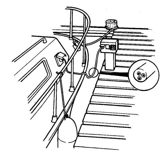
- 2. Route and clamp electric cables so that they will not be exposed to rubbing, damp or bilge water in the keelson.
-
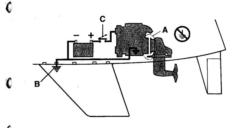
The drive/reverse gear and flywheel cover are electrically insulated (A) from the engine and must never be used as a ground.
- IMPORTANT! The drive/reverse gear and flywheel cover must never be used as a ground or be electrically connected to other equipment such as the radio, navigational equipment, the rudder, bathing steps etc.
Protective grounds for the radio, navigational equipment, rudder, bathing steps or other equipment with separate ground leads must be connected to a common ground terminal ( B ).
4. There must be a main switch (C) connected to the starter battery positive (+) terminal. The main switch should cut off power to all power consuming equipment and should be switched off when the boat is not in use.
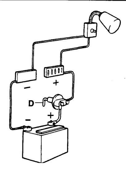
5. If an auxiliary battery is in use, a main switch (D) should be connected between its + terminal and the fuse block. The main switch for the auxiliary battery must cut off all power consuming equipment connected to that battery and be turned off when power is no longer needed.
All equipment connected to the auxiliary battery should have separate switches.
To simultaneously charge two independent battery circuits, fit a Volvo Penta charge distributor (accessory) to the regular generator.
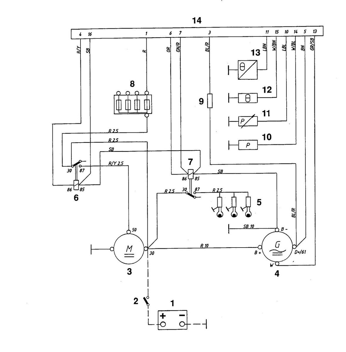
Wiring Diagrams Engine 2010, 2020, 2030, 2040
1
(
- 1. Battery
- 2. Main switch
- 3. Starter motor
- 4. Generator
- 5. Glow plugs. MD2010: x 2. Others x 3.
- 6. Starter relay
- 7. Glow plug relay
- 8. Fuses, max. 15A (+)
- 9. Excitation resistor
- 10. Oil pressure switch, engine
- 11. Oil pressure sensor
- 12. Coolant temperature switch
- 13. Engine coolant temperature sensor
- 14. Connector, 16-pin.
Cable color
BL = Blue OR = Orange Cable areas in mm2 are indicated after the color codes in LBL Light-blue R = Red SB = Black the wiring diagrams. BN = Brown W = White LBN = Light-brown Areas not indicated = 1.0 mm2. Y = Yellow GN = Green A broken line indicates a non-Volvo Penta cable. GR = Gray
39
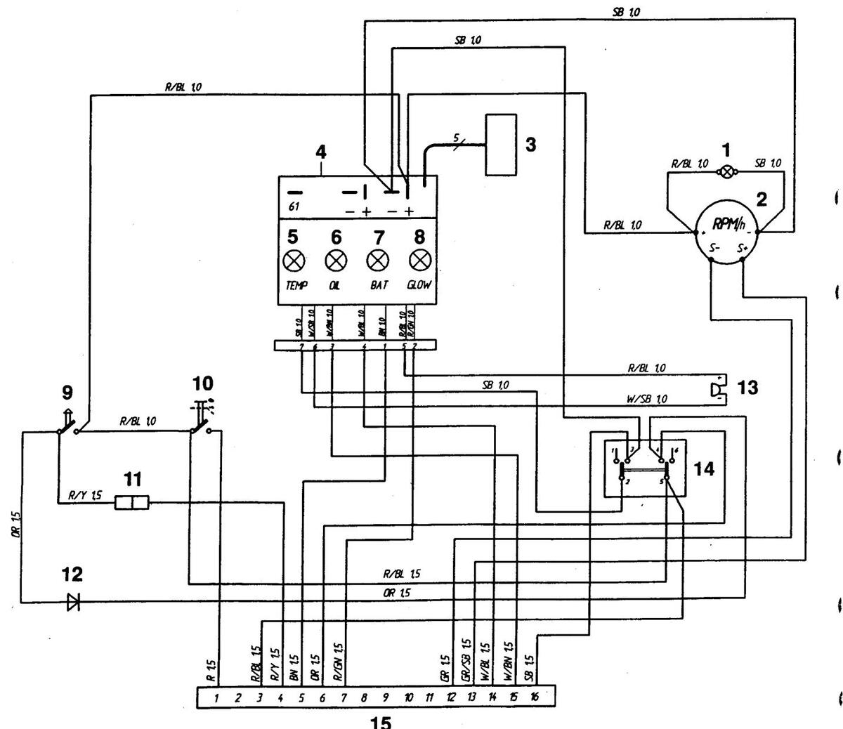
Wiring Diagrams Instrument panel without ignition switch
I
- 1. Instrument lighting
- Tachometer with built-in hours run meter (accessory) Dummy plug
- Connector for connecting extra warning display (accessory)
- Electronics module (alarm) Engine coolant temperature
- warning lamp
- 6. Oil pressure warning lamp
- 7. Charge warning lamp
8. Glow plug indicator lamp
- 9. Starter button
- 10. Button. Instrument panel Off/ On
- Connector for neutral position switch, if fitted (accessory)
- 12. Semiconductor diode
- 13. Alarm
- 14. Rocker switch. Glow plug Alarm test/acknowledge
- 15. 16-pin connector
Cable color
| BL | = | Blue |
| BN | = | Brown |
| GN | = | Green |
| GR | = | Gray |
| OR | = | Orange |
| PU | = | Purple |
| R | = | Red |
| SB | = | Black |
| W | = | White |
| Υ | = | Yellow |
Cable areas in mm2 are indicated after the color codes in the wiring diagrams.
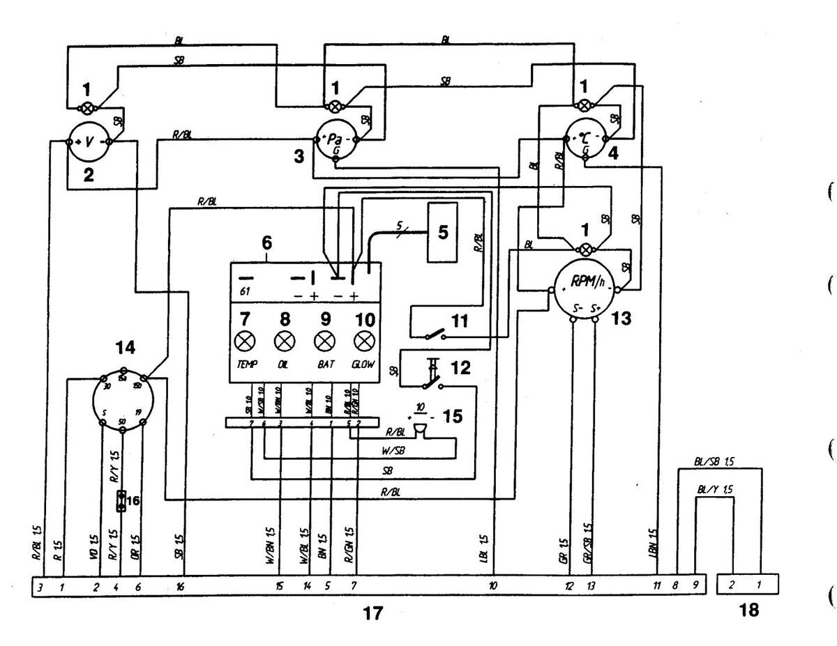
Wiring Diagrams Instrument panel with ignition switch (Alt. 1)
Cable color
| BL | = | Blue |
| BN | = | Brown |
| GN | = | Green |
| GR | = | Gray |
| OR | = | Orange |
| R | = | Red |
| SB | = | Black |
| VO | = | Violet |
| w | = | White |
| Υ | = | Yellow |
- 1. Instrument lighting
- 2. Tachometer with built-in hours run meter (accessorv) Dummy plug
- 3. Connector for connecting extra warning display (accessory)
- 4 Electronics module (alarm) 5. Engine coolant temperature
- warning lamp
- Oil pressure warning lamp
- 7. Charge warning lamp
- 8. Glow plug indicator lamp
- Switch, instrument panel lightina
- 10. Alarm test/acknowledgment switch
- 11. Ignition switch
12. Alarm
- 13. Connector for neutral position switch, if fitted (accessory)
- 14. 16-pin connector
Cable areas in mm2 are indicated after the color codes in the wiring diagrams.
Areas not indicated = 1.0 mm2.
Conversions mm2/AWG*
* American Wiring Gauge
|
mm² |
1.0 | 1.5 | 2.5 | 10 | 16 |
|---|---|---|---|---|---|
| AWG | 16 (17) | 15 (16) | 13 | 7 | 5 |
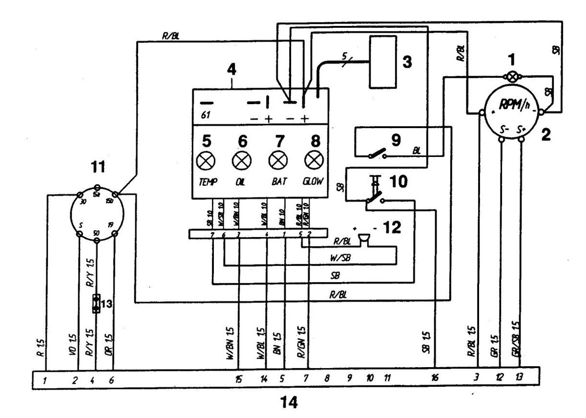
Wiring Diagrams Instrument panel with ignition switch (Alt. 2)
Spring back
Cable color
| BL | Ξ | Blue | OR | = | Orange |
|---|---|---|---|---|---|
| LBL | Ξ | Light-blue | R | = | Red |
| BN | = | Brown | SB | = | Black |
| LBN | = | Light-brown | VO | = | Violet |
| GN | = | Green | W | = | White |
| GR | = | Gray | Υ | = | Yellow |
Cable areas in mm2 are indicated after the color codes in the wiring diagrams.
Areas not indicated = 1.0 mm2.
- I. Instrument lighting
- 2. Voltmeter
- 3. Oil pressure gauge
- 4. Engine coolant temperature gauge
- 5. Connector for extra
- warning display (accessory)
- 6. Electronics module (alarm)
- 7. Engine coolant temperature warning lamp
- 8. Oil pressure warning lamp
- 9. Charge warning lamp
- 10. Glow plug indicator lamp
- 11. Switch, instrument panel lighting
- 12. Alarm test/acknowledgment switch
- 13. Tachometer with built-in hours run meter (accessory). Dummy plug
- 14. Ignition switch
- 15. Alarm
- Connector for connecting neutral position switch, if fitted (accessory)
- 17. 16-pin connector
- 18. 2-pin connector (for additional control panel)
(
S-drive and reverse gear
The S drive and in certain cases the propeller (reverse gear) is equipped with a sacrificial anode which prevents galvanic corrosion. Faulty electrical installation can also cause the break down of the galvanic protection. Damage due to electrolytic corrosion occurs rapidly and is often extensive. For further information see the chapter: "Electrical system"
IMPORTANT! Improperly applied paint or the wrong type of paint on the keel can put the corrosion protection system out of action. For further information on painting see the chapter: Laying up/Launching
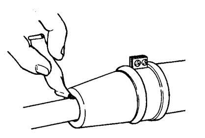
Oil level. Checking and topping up
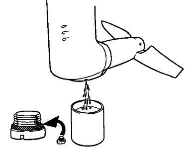
Unscrew (counter clockwise) and remove the dipstick. Wipe off oil. Reinsert the dipstick in the drive/reverse gear without screwing it in . Remove again and check that the oil level is between the MAX and MIN markings on the dipstick. Top up oil if necessary. For oil quality and capacity: See the chapter "Technical Data".
IMPORTANT! The oil level should always be within the MAX and MIN range marked on the dipstick.
Oil change. S-drive
Remove the oil dipstick. Remove the plug on the propeller gear housing and let the oil run out. Check that the plug o-ring is intact. Replace if necessary. Install the plug and o-ring. Top up oil to correct level. For oil quality and capacity: See the chapter "Technical Data".
Oil change. Reverse gear
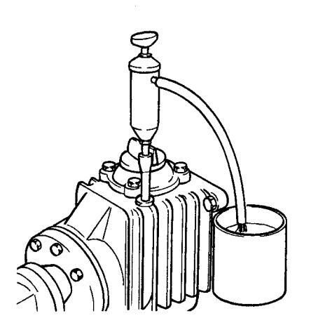
Remove the oil dipstick. Suck up oil using an oil pump through the hole for the dipstick. Top up oil to correct level. Start engine and run at idle speed for a few minutes so the reverse gear oil cooler is filled with oil. Stop engine and check oil level. Top up if required. For oil quality and capacity: See the chapter "Technical Data".
Corrosion protection. Checking/ Replacing
Check the sacrificial anodes, if 50% of the material has been corroded replace the anode (also applies to anodes on the propeller and reverse gear). Remove a folding propeller according to the instructions on the next page. Remove anode by removing the two screws. Scrape mating surface on the drive really clean. Install and tighten the new anode so that there is a good metal contact. Clean the new anode to remove oxidation just before the boat is launched.
- MPORTANT! Use emery paper. Do not use a wire brush or other steel tools when cleaning, as these may damage the galvanic protection.
- IMPORTANT! Use zinc sacrificial anodes for salt water and magnesium anodes for freshwater.
Propeller shaft seal. Reverse gear
If the boat has a Volvo Penta shaft the shaft seal must be vented and lubricated directly after launching.
Vent the bushing by pressing it together while pressing down on the shaft until water appears. Then press in approx. 1 cc water repellent grease into the seal.
IMPORTANT! The seal must be replaced every 500 running hours or every 5th year.
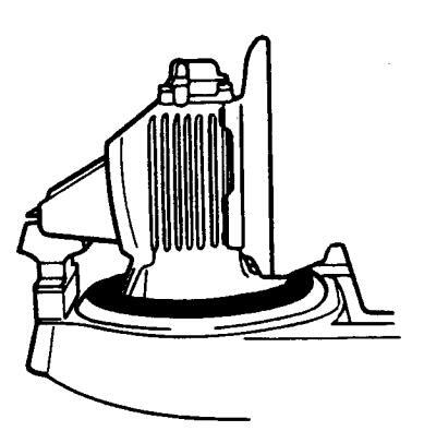
Rubber seal. S-drive
Check the rubber seal between the drive and the hull regularly for cracks and wear.
WARNING! The seal must be changed every seven years or earlier if it is defective. This work should be carried out by an authorized workshop.
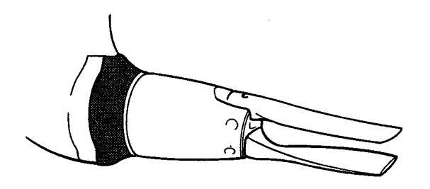
Folding propeller. Removing and installing
WARNING! limmobilize the engine before starting work. Remove the ignition key and turn off the power supply with the main switch.
The line cutter (10) has very sharp edges and must be handled with care.
MPORTANT! The locking screw (5) and the tab washer (7) must be replaced every fourth year. Only a Volvo Penta original locking screw (8) may be used.
- 1. Propeller hub
- 2. Shaft studs
- 3. Propeller blade
- 4. Cogs
- 5. Locking screws
- 6. Nut
- 7. Tab wasch
- 8. Locking screws
- 9. Protective anode
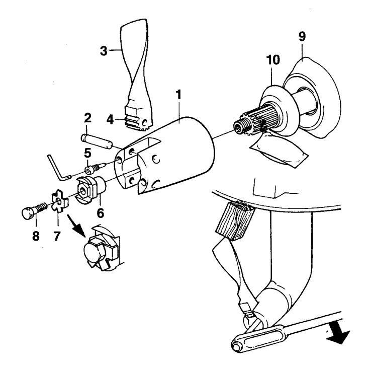
Removing
- Set the control lever in the "Ahead" position.
- Remove the propeller blade by first undoing the locking screws (5) completely and then pressing out the shaft studs (2).
- Fold down the tabs on the tab washer (7). Remove the locking screw (8), tab washer and nut (6). Then pull off the propeller hub (1) and line cutter (10).
- Clean the propeller shaft and propeller hub (1) carefully and grease with water repellent grease.
Installing
- Clean the propeller shaft and propeller hub (1) carefully and grease with water repellent grease.
- Set the control lever in the "Ahead" position.
- Install the line cutter (10) and propeller hub (1) on the shaft. Locate one propeller blade in the hub.
Lock a wooden block between the propeller blade and bottom of the boat. Tighten locknut (6) to 70 Nm. Wrench = 24 mm.
- Locate the tab washer (7) on the nut so the tabs are easily accessible.
- Install locking screw (8) and tighten to 20 Nm.
- Bend one of the tabs against the screw head.
- Apply water repellent grease on the studs (2) and on the propeller blade cogs (4).
- Install one propeller blade in the propeller hub and push in the stud in such a position so the groove in the stud is exactly centered in the hole for the locking screw (5). Tighten locking screw to 20 Nm, use a 6 mm hex wrench.
- Reinstall the other blade in the same way. Check the blades are at the same angle to the propeller shaft and that they move easily.
45
Laving up and launching
Before taking the boat out of the water for winter/out-of-season storage have an authorized Volvo Penta workshop inspect the engine and other equipment. Have any necessary repairs or service work carried out so that your boat is in top condition for the new season.
Inhibition should be carried out to ensure that the engine and transmission are not damaged while out of commission during the winter/off-season. It is important this is done properly and than nothing is forgotten. We have therefore provided a checklist covering the most important points.

WARNING! Read the chapter on Maintenance carefully before starting work. It contains instructions on how to carry out the most common maintenance and service operations safely and correctly.
Inhibiting
The following are best carried out with the boat in the water:
- Change engine oil and replace oil filter.
- Change oil in the reverse gear.
- Replace fuel filter. Replace fuel pre-filter if installed
- Run the engine to normal operating temperature.
- Take the boat out of the water:
The following should be carried out with the boat out of the water:
- Clean the hull and drive directly after taking up the boat (before it dries).
- MIMPORTANT! Be careful when cleaning with a high pressure water spray. Never direct the water jet at the propeller shaft seal, grommets etc.
- Change oil in the drive.
- Clean the vacuum valve and seawater filter (accessory).
- Clean and inhibit the seawater system.
- Remove the impeller from the seawater pump. Store the impeller in a sealed plastic bag in a cool place.
- Check the condition of the engine coolant antifreeze. Top up if required.
MPORTANT! An anti-corrosion mixture in the engine coolant system provides no protection against freezing. If there is any possibility the engine will be subjected to freezina temperatures then the system must be drained
1
A
- Drain any water and contaminants from the fuel tank. Fill the tank completely with fuel to avoid condensation.
- Clean the outside of the engine. Do not use a high pressure spray to clean the engine. Touch up any damaged areas of paintwork with Volvo Penta original paint.
- Check all control cables and treat with rust inhibitor
- Repair any damaged areas of paintwork with Volvo Penta original paint, NOTE! Read the special instructions on painting the drive under the heading: "Painting the drive and hull".
- Disconnect battery leads. Clean and charge the batteries. NOTE! A poorly charged battery may burst as a result of freezing.
- Spray electrical system components with moisture repellent sprav.
- Remove the propeller for storage. Grease the propeller shaft using water repellent grease. Disassemble folding propellers, clean and grease.
- Check the rubber seal between the drive and hull carefully.
Bringing out of storage
- Check oil level in the engine and drive/reverse gear. Top up if required. If there is inhibiting oil in the system drain and fill with new oil, change oil filter. For correct oil grade: See the chapter "Technical Data".
- Drain the antifreeze from the seawater system.
- Install the impeller in the seawater pump (replace if the old one looks worn).
- Close/tighten drain cocks/plugs.
- Check drive belts.
-
Check the condition of rubber hoses and tighten hose clamps.
- Check engine coolant level and antifreeze protection. Top up if necessary.
- Connect the fully charged batteries.
- Paint the drive and hull: See following page.
- Check the sacrificial anode on the drive. If there is less than 50% of the anode left it must be replaced. Clean with emery cloth just before the boat is launched.
- A IMPORTANT! Do not use a wire brush or other steel tools when cleaning, as these may damage the galvanic protection.
- Reinstall the propeller.
- Launch the boat. Check for leaks.
- Vent and lubricate the propeller shaft seal (reverse gear).
- Start engine. Check that there are no fuel, engine coolant or exhaust gas leaks and that all control functions are operating.
Painting the drive and underwater hull
C
C
Drive
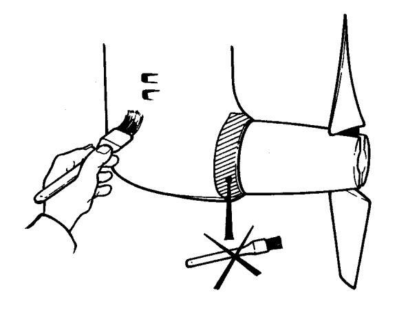
Before treating the drive with anti-fouling agent any damaged paintwork must be repaired. Sand down metal surfaces lightly using a 120 grade paper and a finer grade for painted surfaces. Wash off using thinners or similar. Any pores in the surface should be filled and sanded down. Paint using Volvo Penta original primer and topcoat. Let the paint dry. A further two coats of Volvo Penta anti-fouling primer should then be applied. Let them dry. A further two coats of Volvo Penta anti-fouling should then be applied.
A IMPORTANT! The sacrificial anodes on the drive must not be painted or treated with Teflon. This also applies to stainless or bronze propellers.
Use of anti-fouling agents is not permitted in all countries. Please make sure that it is permitted where your boat is to be used. If anti-fouling agents are not permitted we recommend that a pure Teflon®* agent be applied onto the original paintwork on the drive without sanding it down first.
*Teflon is the registered trademark of the Du Pont Corp.
Underwater hull
All types of paints with anti-fouling properties are poisonous and cause damage to the marine environment. Avoid the use of such agents. Most countries have introduced legislation controlling the use of antifouling agents. Always abide by these regulations. In some cases these agents are completely forbidden for use on leisure craft used in fresh water. If the boat is easy to take up on land then we recommend Teflon treatment combined with mechanical cleaning several times during the season.
For larger craft this is not practicable. If the boat is in an area where the water quickly produces fouling then anti-fouling paints must probably be used. If this is the case use a copper-based paint containing copper cyanate and not copper oxide .
IMPORTANT! Leave an area of 10 mm around the drive unpainted.
Tin-based agents (TBT) must not be used. Check the legislation that applies where the boat is to be used. Wait for the paint to dry before launching the boat.
Fault-tracing
| Problem | Probable cause |
|---|---|
| Starter motor not turning (or slow) | 1, 2, 3 |
| Engine fails to start | 4, 5, 6, 7, 8, 9 |
| Engine starts but stops again | 6, 7, 8, 9 |
| Engine is difficult to start | 6, 7, 8, 9 |
| Engine does not reach correct speed at wide open throttle (WOT) | 7, 8, 9, 10, 11, 12, 13, 18 |
| Engine knocks | 14 |
| Engine runs unevenly | 6, 7, 8, 9, 13, 14 |
| Engine vibrates | 18, 19 |
| High fuel consumption | 10, 11, 13, 15, 18 |
| Black exhaust smoke | 5, 13, 15, 18 |
| Blue or white exhaust smoke | 15, 25 |
| Low oil pressure | 16, 17 |
| Engine coolant temperature too high | 20, 21, 22, 23, 24 |
| No or poor charging | 2, 26 |
List of probable causes
-
1. Discharged battery
- 2. Loose connection/open-circuit
- 3. Fuse (in the relay box) blown.
- 4. Stop control pulled out
- 5. Inadequate pre-heating
- 6. Lack of fuel
- 7. Blocked fuel filter
- 8. Air in the fuel injection system
- 9. Water/contaminants in the fuel
- 10. Boat abnormally loaded
- 11. Fouling on underwater hull/drive/propeller
- 12. Limited speed control lever movement
- 13. Insufficient air supply
- 14. Engine coolant temperature is too high
- 15. Engine coolant temperature is too low
- 16. Lubricating oil level too low.
- 17. Blocked fuel filter
- 18. Defective/incorrect propeller
- 19. Defective engine mounting
- 20. Too little coolant
- 21. Blocked seawater intake/pipe/filter
- 22. Circulation pump drive belt slipping
- 23. Defective impeller
- 24. Defective/incorrect thermostat
- 25. Lubricating oil level too high
- 26. Generator drive belt slipping
Technical Data
General
|
Engine designation
No. of cylinders Cylinder bore Cylinder stroke Overall cylinder displacement Power see sales literature |
MD2010B
2 67 mm 64 mm 0.45 liter |
MD2020B
3 67 mm 64 mm 0.68 liter |
MD2030B
3 75 mm 72 mm 0.95 liter |
MD2040B
3 84 mm 90 mm 1.50 liter |
( |
|---|---|---|---|---|---|
|
Idling speed
Rotation, viewed from in front Max. permitted rake backwards while running Max. list while running Valve clearance (stopped, cold engine) |
850 ± 25 rpm
Clockwise 20° 30° |
850 ± 25 rpm
Clockwise 20° 30° |
850 ± 25 rpm
Clockwise 20° 30° |
850 ± 25 rpm
Clockwise 20° 30° |
|
| inlet and outlet |
0.20 mm
98 kg |
0.20 mm
116 kg |
0.20 mm
129 kg |
0.20 mm
179 kg |
( |
Lubrication system
| Oll capacity Incl. on Inter, approx | |||||
|---|---|---|---|---|---|
| no engine inclination | 1.8 liters | 3.4 liters | 4.3 liters | 6.4 liters | 6 |
| Oil grade (in accordance with API system) | CD | CD | CD | CD | Ų |
| Viscosity at -5° - +50°C* | SAE 15W/40, | SAE 15W/40, | SAE 15W/40, | SAE 15W/40, | |
| • | SAE 20W/50 | SAE 20W/50 | SAE 20W/50 | SAE 20W/50 | |
| Oil drain plug tightening torque | 30–40 Nm | 30–40 Nm | 30–40 Nm | 30–40 Nm | |
| (3.0–4.0 kpm) | (3.0–4.0 kpm) | (3.0–4.0 kpm) | (3.0–4.0 kpm) | ||
* Steady ambient temperature
| l | ||||
|---|---|---|---|---|
| x 1 | x 1 | x 1 | x 1 | |
|
75° ± 2°C
87°C |
75° ± 2°C
87°C |
82° ± 2°C
95°C |
82° ± 2°C
95°C |
|
| 2.1 liters | 3.0 liters | 4.0 liters | 6.9 liters | |
| ĺ | ||||
| 12 V | 12 V | 12 V | 12 V | • |
| 15 A | 15 A | 15 A | 15 A | |
| 70 Ah | 70 Ah | 70 Ah | 70 Ah | |
| 14 V/60 A | 14 V/60 A | 14 V/60 A | 14 V/60 A | |
| 840 Ŵ | 840 W | 840 W | 840 W | É |
| 0.7 kW | 0.7 kW | 1.2 kW | 2.0 kW | |
|
x 1
75° ± 2°C 87°C 2.1 liters 12 V 15 A 70 Ah 14 V/60 A 840 Ŵ 0.7 kW |
x 1 x 1
75° ± 2°C 75° ± 2°C 87°C 87°C 2.1 liters 3.0 liters 12 V 12 V 15 A 15 A 70 Ah 70 Ah 14 V/60 A 14 V/60 A 840 W 840 W 0.7 kW 0.7 kW |
x 1
75° ± 2°C 75° ± 2°C 82° ± 2°C 87°C 87°C 95°C 2.1 liters 3.0 liters 4.0 liters 12 V 15 A 70 Ah 14 V/60 A 840 W 840 W 0.7 kW 0.7 kW 1.2 kW |
x 1
75° ± 2°C 75° ± 2°C 82° ± 2°C 82° ± 2°C 87°C 87°C 95°C 95°C 2.1 liters 3.0 liters 4.0 liters 6.9 liters 12 V 15 A 70 Ah 14 V/60 A 840 W 0.7 kW 0.7 kW 1.2 kW 2.0 kW |
Fuel specification
Fuel must meet national and international standards at least. For example:
EN 590 (with national environmental and cold standards)
ASTM D 975 No 1-D and 2-D
JIS KK 2204
Sulfur content: According to statutory requirements.
Fuels with extremely low sulfur contents ("urban diesel" in Sweden and "city diesel" in Finland) can cause a drop in output of 5% and an increase in fuel consumption of 2–3%.
Reverse gear
| Type designation | MS2L-D, MS2A-D |
|---|---|
| Gear ratios: | |
| MS2L-D | 2.3:1 |
| MS2A-D | 2.37:1; 3.0:1 |
| Angle (output shaft): | |
| MS2L-D | 0° |
| MS2A-D | 7 ° |
| Oil capacity, approx | 0.8 liters |
| Oil grade (in accordance with API system) | CD |
| Viscosity | SAE 15W/40 |
| Weight | 17 kg |
| Tightening torque: | 5 |
| oil drain plug | 20 + 5 Nm (2 ±0.5 kpm) |
| on under plug |
C
Sailing boat drive
| Type designation | 120S–D |
|---|---|
| Gear ratio | 2,48:1 |
| Oil capacity, approx | 2.8 liter |
| volume difference minmax | 0.07 liter |
| Oil grade (in accordance with API system) | CD |
| Viscosity | SAE 15W/40 |
| Weight | 28 kg |
|
Tightening torque:
oil drain plug |
10 ±5 Nm (1 ±0.5 kpm) |


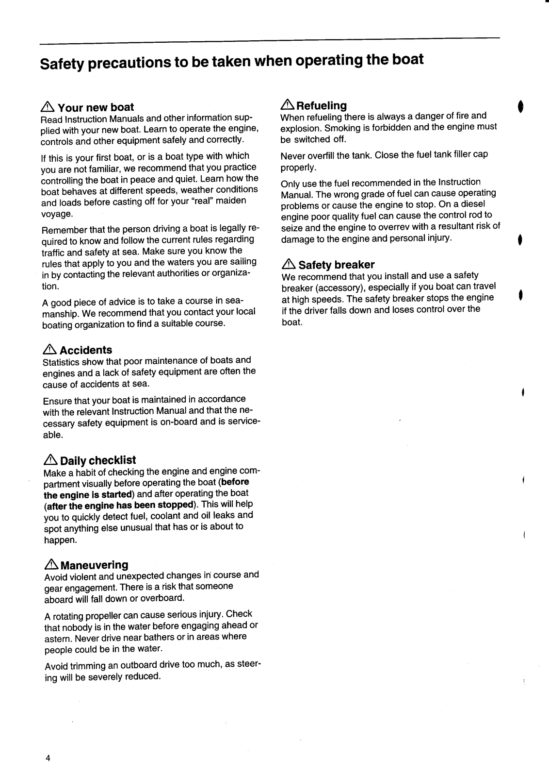


 Loading...