

Page 1
Page 2

FOREWORD
Before you start your new Volvo Penta marine engine, you are advised to read through
this instruction book carefully. It contains all the information you need to run and
service your engine in the best possible way.
Volvo Penta has built up an extensive service organization with service workshops with
specially trained personnel at your service.
Always contact your local Volvo Penta representative for advice and when in need of
service and parts.
We are convinced that the demands on good running economy and top performance,
which you have every right to expect of a quality product, will be met and that your
engine will serve you faithfully on many pleasant cruises.
Warranty Certificate
A warranty certificate is supplied with each new engine. It contains the warranty
conditions for the engine and should be studied carefully.
Included in the warranty certificate is a report card which is to be completed by the
dealer or boat seller and forwarded to Volvo Penta.
However, if our warranty is to apply, it is an absolute condition that the measures given
in the "Check and Service Scheme" are carried out and that your engine and
equipment are looked after according to the instructions in this book. When in doubt,
always get in touch with an authorized Volvo Penta dealer.
In all correspondence with your dealer and when ordering parts, always state the type
and designation and serial number of the engine and reverse gear or drive (see
starboard side of engine).
Make certain that the engine's specification coincides with what is described in this
instruction book.
AB VOLVO PENTA
Technical Information
Page 3

- 1 -
CONTENTS
Instruments and controls ..................................................................2
General information...............................................................................3-4
Running instructions.............................................................................5-7
Starting the engine ........................................................5
Running .........................................................................6
Shutdown procedure .....................................................6
Technical description ..............................................................8-10
Checks and service scheme .................................................................11
Checks and service .............................................................12-25
Daily checks before starting .......................................12
Checks every 14 days ...........................................12-13
Service every 50 hours of operation......................13-14
Service every 100 hours of operation....................15-21
Service when laying up and launching ..................22-25
Fault tracing scheme ..................................................................26
Technical data ........................................................27-28
Wiring diagram ..................................................................29
On board data .................................................................30
Engine component guide ..............................................................31-34
S-drive 110S ..............................................................35-37
Index, alphabetical order ..................................................................38
Page 4
- 2 -
INSTRUMENTS AND CONTROLS
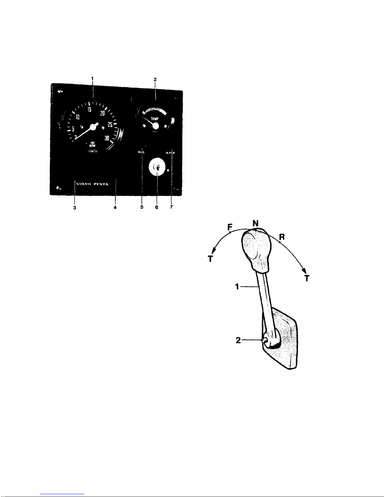
INSTRUMENT PANEL
1. Rev counter
2. Temperature meter for cooling water
Green scale - normal emperature.
3. Switch. for extra lighting
4. Instrument panel illumination
5. Warning lamp "low oil pressure".
If lit - stop engine, oil pressure insufficient.
6 Key switch
7. Warning lamp "No battery charging"
If lit - no charging.
CONTROL SYSTEM
Volvo Penta Single Control System
For side mounting
1. Control lever
2. Disengaging button
Push in the button when the
control lever is in neutral and
move the lever a bit forwards.
Release button. The lever is now
used only for engine speed
control. To use the lever for both
engine speed control and gear
charging, push in the button and
pull back the lever to neutral.
N=Neutral position
F=Control lever in position for running
"forward".
R=Control lever in position for running "reverse”
T= Engine speed control
Page 5

- 3 -
GENERAL INFORMATION
Important information on the function of your engine.
FUEL Use diesel fuel oil of quality "Autodiesel". Poorer fuel quality
can cause interruptions in operation.
LUBRICATING OIL Use only oil of quality CD (DS) according to the API system.
Volvo Penta oil for diesel engines can be used with advantage
since it meets these quality demands. See under "Technical
Data" concerning the viscosity if any other oil is used.
RUNNING IN A new marine engine must be run-in with due care during the
first 20 hours of operation. If full output is taken out during
this time, it should only be done for short periods.
Oil change. Change the engine oil and oil filter after the engine
has been run for 20 hours. See further under "Checks and Service".
ENGINE SPEED Max speed: MD 11 C, MD 1 7C 41.7 rev/sec (2500 rpm)
For choice of correct propeller, refer to the Volvo Penta propeller diagram. Check the
engine speed with normal load in the boat. In order to utilize the maximum performance
of the engine, an engine speed as high as possible should be chosen but not, however,
higher than 41.7 rev/sec (2500 rpm).
Note: When the boat has been in the water for some time, the speed and max rpm can
drop due to marine growth on the hull. Prevent marine growth by painting the bottom of
the boat with anti-fouling paint. See under "Measures taken when launching".
Page 6

- 4 -
GENERAL INFORMATION
SAFETY EQUIPMENT
Irrespective of whether the boat is being used for long cruises or short bathing trips, the
boat should be equipped with the safety equipment listed below. It can, of course, be
supplemented further according to personal tastes. Investigate at regular intervals to
ensure that there is safety equipment on board and that it is in working order.
LIFE JACKETS for all on board
FIRE EXTINGUISHER, approved, at least one and installed where it is easy to get at.
DISTRESS ROCKETS and matches. Packed watertight. FIRST AID BOX
TOOLS suitable for the equipment on board ON BOARD KIT containing, e.g. impeller,
etc. ANCHOR with line.
RADAR REFLECTOR
RADIO for listening to e.g. weather reports. COMPASS which is deviated.
BOAT HOOK and PADDLE
MOORING ROPES
FOGHORN and whistle FLOATING ANCHOR TORCH
PREPARATIONS BEFORE STARTING
Make sure that:
There is no FUEL LEAKAGE
There is no WATER LEAKAGE from the engine and hull There is no OIL LEAKAGE
There is no SMELL OF LIP GAS in the deep cavities in the boat or elsewhere The OIL
LEVEL is correct.
There is enough FUEL for the planned voyage.
The proper NAUTICAL CHARTS are on board for the planned voyage.
If there are persons on board who have never been on the boat before, inform them
how the boat functions and where the Life Jackets and Fire Extinguisher are located.
Also inform them of anything more you think necessary from a safety point of view.
Should anything unexpected happen during the voyage, it is often too late to tell those
on board how safety equipment works.
Page 7
- 5 -
RUNNING INSTRUCTIONS
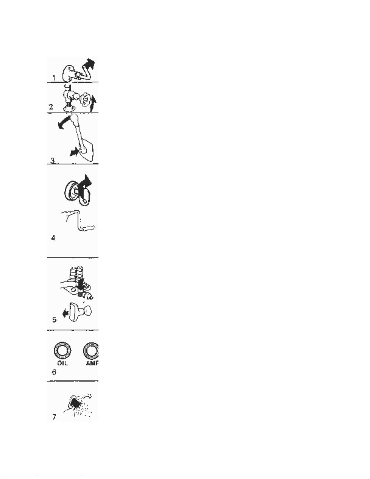
START THE ENGINE
Switch on the main switch. Start the engine room fan (if fitted) and
let it run several minutes before starting the engine.
Open the cock for cooling water intake.
Disengage the engine speed control from the gear changing as
follows: Move the control lever to neutral, push in the red
disengaging button, and move the lever slightly forwards. Release
the button. The lever can now only operate the engine speed.
Check to make sure that the stop control is pushed in.
Turn the key switch one stage to the right. The warning lamps for
battery charging and oil pressure should now go on. If there is an
alarm system fitted, the siren should sound. Push in and turn the
key further to the right to start the engine. Release the key when
the engine starts.
Handstarter (standard MID11C, extra MD17). When the engine is
started with the starting crank, the de-compression handles on the
rocker arm covers should be raised upright (see 16, pages 31-32).
Return the de-compression handles for running when the cranking
has got the engine up in speed.
Cold weather.
MD11: Starting is facilitated if the cold-start control is pushed down,
or the cold-start control (accessory) is pulled out. The cold-start
button returns automatically. The cold start control must be pushed
in after the engine
has started.
MD 17: The engine has a built-in automatic cold-start device.
Check immediately after starting that the warning lamps for the oil
pressure and battery charging are not lit. If any of the lamps are
alight, the engine must be stopped immediately and the cause
investigated. If an alarm system is fitted (accessory) the siren
should be silent.
Run the engine warm at rapid idle. Check to make sure that the
cooling water flows out with the exhaust gases. Note. The keyswitch should always be switched on as long as the engine is
running to ensure that there is battery charging.
Page 8
- 6 -
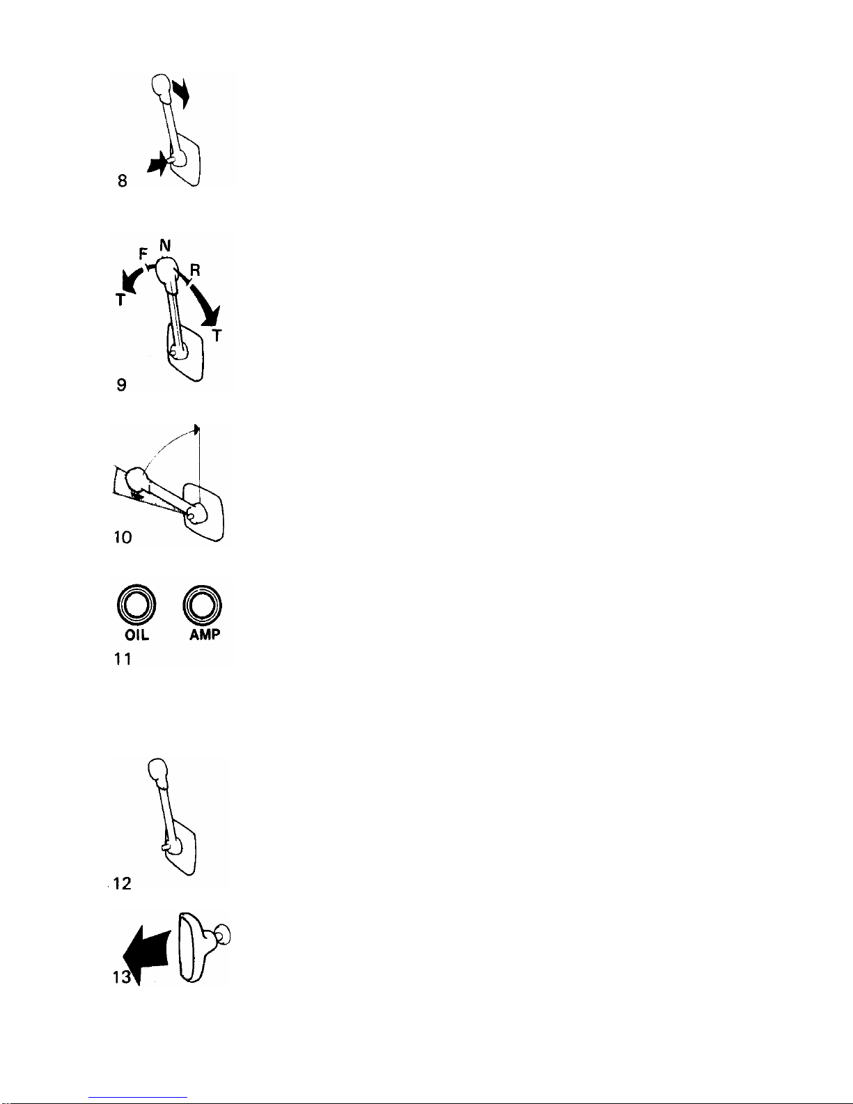
Reduce to idle and check that the engine is running smoothly.
Engage the control lever for gear-charging as follows:
Push in the red disengaging button when the lever is in neutral.
Release the button. The control lever can now be used both for
gear changing and engine speed.
RUNNING
The single lever control has both engine speed and manoeuvering
functions.
F = Forward
R = Reverse
N = Neutral
T = Engine speed control
To achieve good running economy, the engine should not be run
at max speed for a longer period.
Check during running that the temp meter, and also the lamps for
battery charging and low oil pressure are not lit. If an alarm system
is fitted and the siren sounds, - Stop the engine immediately and
investigate the cause.
SHUTDOWN PROCEDURE
Before shutdown the engine should be allowed to idle for a few
minutes with the control lever in neutral.
Stop the engine by pulling the stop control when the engine is
idling. Then turn back the key switch to the initial position.
Page 9
- 7 -
RUNNING INSTRUCTIONS
Switch off the main switch. NOTE. This switch must never be
switched off before engine has stopped. Close the fuel and cooling
water cocks if the boat is not going to be used for some time.
Check for leakage before leaving the boat.
In cold weather and whenever there is a risk of freezing, the
cooling water must be drained from the engine and reverse gear.
(See pos. 14 and 10, pages 31-32).
Page 10
- 8 -
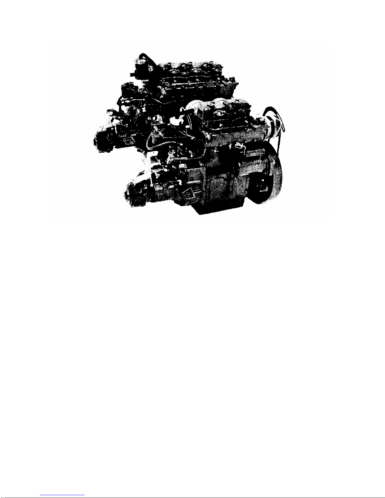
TECHNICAL DESCRIPTION
MD 11 C and MD 1 7C, are 2 respectively 3 cylinder, 4 stroke marine diesel engines,
with direct injection and sea water cooling.
ENGINE ASSEMBLY
The crank case, cylinders and cylinder heads are made of cast iron. The engines
have replaceable cylinder liners and overhead valves.
LUBRICATION SYSTEM
The lubrication system has a full-flow oil filter which cleans the oil before it reaches
the lubrication points. The oil pump has a relief valve which prevents the oil pressure
from becoming excessive.
ELECTRICAL SYSTEM
The engine has a starter motor and an alternator with a built-in rectifier. Voltage
regulation is done by a transistorized regulator mounted on the alternator. The
alternator can charge two batteries, independent of other, if a charging distributor
(accessory) is fitted to the alternator. A main fuse, which can easily be reconnected,
is fixed to the engine. It protects the electrical system from damage in the event of
overloading. The wiring diagrams for the engine and instrument panel are shown on
page 29.
Page 11
- 9 -
TECHNICAL DESCRIPTION
FUEL SYSTEM
The fuel system has a feed pump with a fine filter, fuel filter with a fine filter insert,
injection pump and injectors. The feed pump is of the membrane type and has a hand
primer lever. There is a built-in cold start device. On the MD11C it is controlled
manually and on the MD17C it is operated automatically.
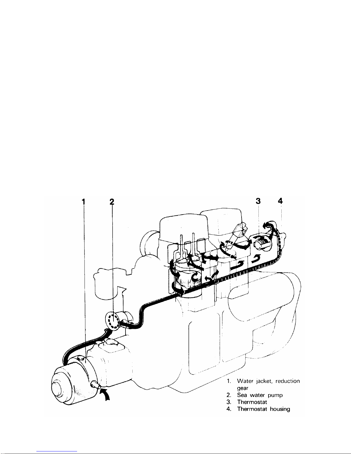
COOLING SYSTEM
The engine is cooled by sea water. The cooling system has a sea water pump and a
water distribution housing with a thermostat,
The sea water pump has an impeller made of neoprene rubber, which is driven via a
rubber flange from the camshaft.
The thermostat in the water distribution housing regulates the water flow, so that
water is always flowing in the exhaust manifold and out in the exhaust elbow,
regardless of whether the engine is cold or hot.
Page 12
- 10 -
TECHNICAL DESCRIPTION
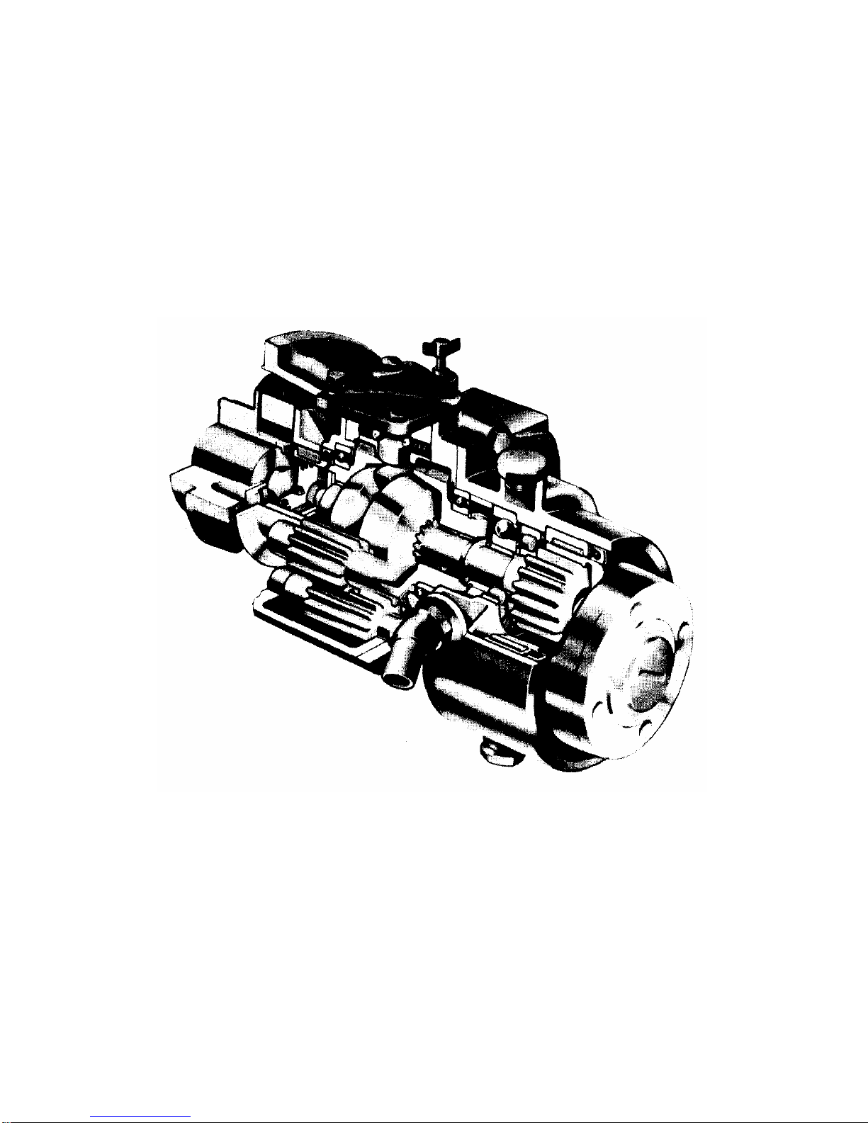
REVERSE GEAR
The Volvo Penta reverse gear, type Mono Shift, has a reduction ratio of 1.9 1: 1. The
reduction gear is integrally built with the reverse gear. The power transmission from
the engine to the reverse gear is via a rubber flange.
For operating "Forward" and "Reverse" the Volvo Penta patented cone clutch 'is
used, which ensures smooth and quiet engagement. Very small forces are required to
operate the reverse gear.
Reverse Gear type Mono Shift (MSB).
Page 13
- 11 -
CHECKS AND SERVICE SCHEME
Checks and service should be carried out regularly in accordance with the intervals
given below. Let an authorized Volvo Penta Service Shop look after your engine.
CHECK DAILY BEFORE STARTING that
Page
The oil level in the engine is between the marks on the dipstick .............................12
CHECK EVERY 14 DAYS that
The oil level in the reserve gear is between the marks on the dipstick ....................12
The electrolyte level in the battery is correct ..........................................................13
The belt tension is sufficient to prevent the alternator from slipping ........................13
SERVICE EVERY 50 HOURS OF OPERATION
Change the oil in the engine .................................................................................13
Change the oil in the reverse gear ........................................................................14
Check and adjust the valve clearance ...................................................................14
SERVICE EVERY 100 HOURS OF OPERATION
OR AT LEAST ONCE EACH SEASON
Change the oil filter ..............................................................................................15
Clean the air filter .................................................................................................15
Check and change the pulley belt for alternator .....................................................16
Check-tighten the cylinder head bolts ....................................................................16
Check the cooling system ................................................................................16-17
Check the electrical system (fuses etc.) ...........................................................17-19
Check the fuel system, filter, strainer, injector, venting ......................................19-21
SERVICE WHEN LAYING-UP AND LAUNCHING
THE BOAT
Inhibiting scheme l. To be carried out with boat in water ........................................22
Inhibiting scheme ll. To be carried out with boat on land ........................................23
Service in connection with launching .....................................................................24
Venting of fuel system ..........................................................................................21
Page 14
- 12 -
CHECKS AND SERVICE
CHECK DAILY BEFORE STARTING
OIL LEVEL IN ENGINE
Each day before starting, check that the oil
level is between the marks on the dipstick.
Top up with oil if necessary, through the oil
filler hole. NOTE. Do not top up above the
max mark. MD11: Check that the dipstick is
screwed down so that no leakage can occur.
Concerning the choice of oil, see under
"Technical Data".
CHECKS EVERY 14 days
OIL LEVEL IN REVERSE GEAR
Unscrew the dipstick, wipe it clean and
insert it again without screwing it down. Pull
up the dipstick and check the oil level,
which should be between the marks. If
necessary top up with oil. Do not top up
above the Max mark.
Screw down the dipstick again. Note that
there is a sealing washer on the dipstick.
Concerning choice of oil, see under
"Technical Data".
Page 15

- 13 -
CHECKS AND SERVICE
ELECTROLYTE LEVEL IN BATTERY
The level should be between 5-10 mm (3/16"-3/8") above the cell plates in the
battery. If necessary top up with distilled water. NOTE. Observe great care when
doing this, as the electrolyte is corrosive, and the gas which is formed is explosive.
BELT TENSION
Correct belt tensioning is necessary for full
alternator output. The belt should be so
tensioned that it can be depressed 5 mm
(3/16") with the thumb midway between the
pulleys.
The belt can be tensioned after slackening
the alternator mounting belts.
A well worn or cracked belt should be
replaced.
SERVICE EVERY 50 HOURS OF OPERATION
OIL CHANGE IN ENGINE
NOTE: Since the printing of the book an
alteration has been made in the method of
changing oil. In the case of the MD11C it has
been indicated that the oil screen is to be
removed. If the oil screen for the MD11C
does not have a Wedged handle it must not
be removed. Remove only the oil dipstick
and push the suction tube through the hole.
This procedure has to be followed also on
earlier engines.
With a new or newly reconditioned engine,
the oil should be changed for the first time
after 20 hours of operation, and thereafter
every 50 hours of operation. Run the engine
warm. Suck up the oil with a pump through the dipstick hole.
Page 16

- 14 -
CHECKS AND SERVICE
On the MD11C the plug together with the oil
strainer must first be removed. NOTE.
When removing the strainer the gasket
must be checked. Re-tighten well.
Fill oil to correct level. Refer to "Technical
Data" regarding choice of oil.
NOTE. The oil filter should also be changed
at every other oil change.
OIL CHANGE IN REVERSE GEAR
The oil can be drained from the reverse
gear by removing the plug under it, or by
sucking up the oil through the dipstick hole
with the help of an oil scavenging pump.
Fill with oil through the filler hole to the
correct level. NOTE. Do not fill above the
Max mark on the dipstick. Regarding
choice of oil, refer to "Technical Data".
VALVE CLEARANCE
The valve clearance should be checked
and adjusted by an authorized workshop.
Refer to "Valves, Technical Data". When
necessary, check and adjust the
decompression device's action on the
exhaust valve.
Page 17

- 15 -
CHECKS AND SERVICE
SERVICE EVERY 100 HOURS OF OPERATION
OR AT LEAST ONCE EACH SEASON
OIL FILTER
The oil filter should be replaced for the first time after 20 hours of operation during the
running-in period and subsequently at every other oil change. Unscrew and discard
the oil filter.
Coat the new oil filter's rubber seal with oil.
Check the contact surface on the engine
and screw in the filter by hand until it
touches the contact surface. Turn the filter a
further half turn, not more.
NOTE. Use only genuine oil filters.
Start the engine, run at idling and check that
the oil pressure lamp goes out.
Check oil level and that there are no leaks
from the oil filters contact surface.
CLEANING OF AIR FILTER
The air filter should be removed and
cleaned after every 100 hour operation
period or once per season. Loosen the
clamps with a screwdriver and remove the
filter.
Clean the filter with diesel fuel and blow it
clean with a compressed air gun. Soak
them in thin engine oil.
Let the engine oil drain and refit the filter.
Page 18

- 16 -
CHECKS AND SERVICE
CHECKING AND REPLACEMENT OF PULLEY BELT
Check the belt carefully, both for wear and
cracks. Any sign of such, then the belt must
be replaced. Loosen the alternator mounting
bolts so that the belt can be removed. Dry
the pulley grooves before fitting the new belt.
Tension the belt so that the belt can only be
pressed down 5 mm (3/16") between the
pulleys. After a few hours running, recheck
belt tensioning and adjust if necessary.
RETIGHTENING CYLINDER HEAD BOLTS
Retighten each bolt with a torque wrench before
starting a new engine or an overhauled engine for
the first time, and after 20 hours of operation. The
valve clearance should always be checked after the
bolts have been retightened. Sequence for
tightening the bolts is shown in the figure opposite.
Torques:
Nos. 1, 2, 3 and 4 are torqued to 11 kpm (79 lbft)
Nos. 5 and 6 are torqued to 4.5 kpm (32 lbft)
CHECKING OF COOLING SYSTEM
The cooling system is working normally when the temp gauge is registering within the
green scale and the alarm (if fitted) is silent. Too high water temperature (red scale,
siren is sounding) can be due to the following: blocked water intake, defective
impeller or the flange in the sea water pump, faulty thermostat or temp sender. Be
observant for water ingress when working with the cooling system.
Page 19

- 17 -
CHECKS AND SERVICE
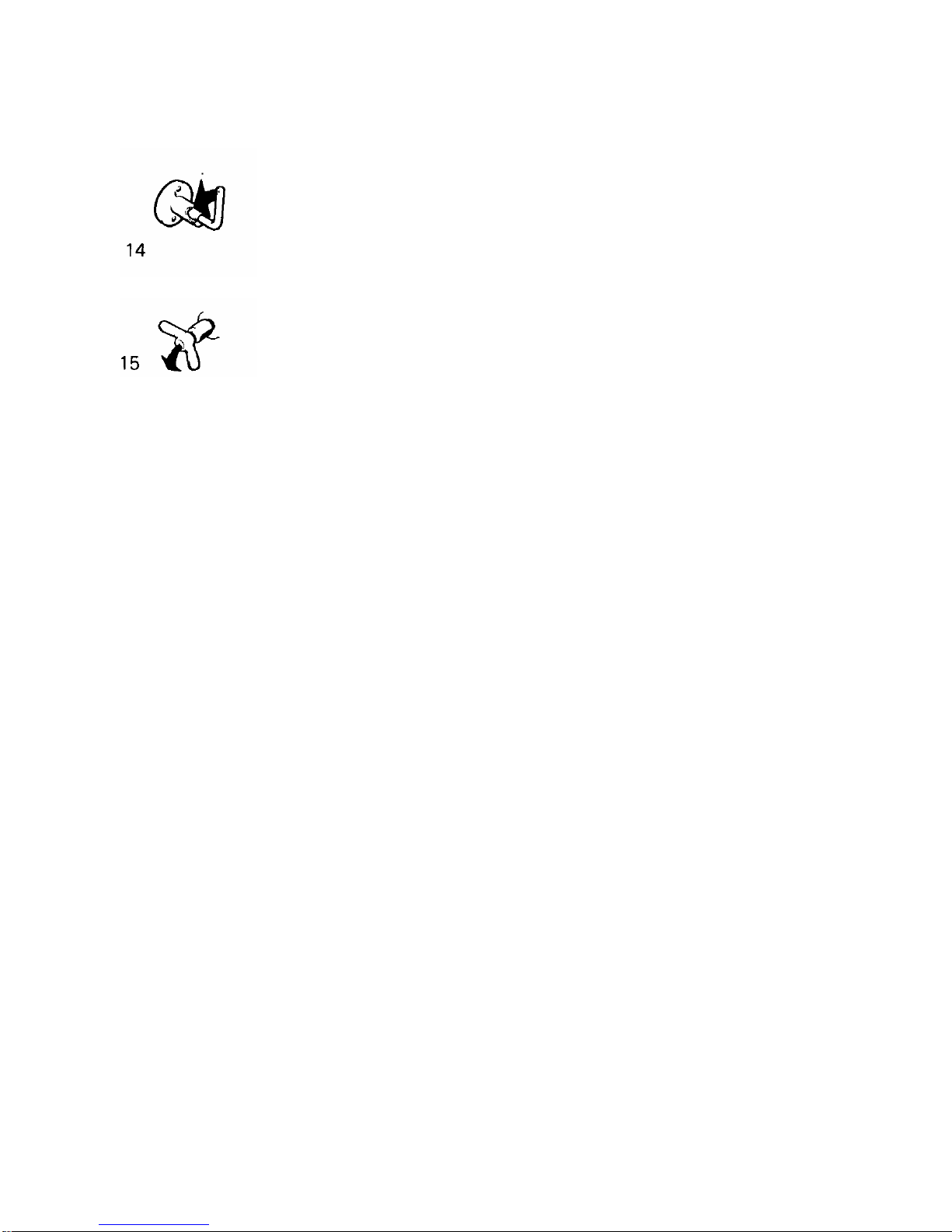
Checking and changing of the impeller
The impeller can be damaged by e.g. lack of
water. Remove the cover on the sea water
pump. Draw out the shaft enough so that the
impeller's locking screw can be screwed out.
Holding the shaft, draw off the impeller. If the
impeller is damaged it must be changed.
Lock the impeller on the shaft with the
locking screw.
The flange is defective if the impeller and the
shaft can be rotated. A new flange can be
fitted after the pump has been removed.
Refit the cover with its gasket.
ELECTRICAL SYSTEM
Alternator
The engine is equipped with an
alternator. To ensure that the alternator,
with the builton regulator, functions
without interruptions, the following
important points must be observed:
1. The main switch must never be
switched off until the engine has
stopped.
Otherwise would ruin the charging
regulator
2. The battery connection poles must
never be mixed up. A plus sign and a
minus sign are marked on the
respective poles. The minus pole is
connected greased and well tightened.
Page 20

- 18 -
CHECKS AND SERVICE
3. Re wiring between the charging circuits may not be carried out while the
engine is running.
Fit a Volvo Penta charging distributor
(accessory) on the alternator when more
than one battery is connected.
4. Observe the following whenever the
engine is started with an auxiliary
battery:
Let the ordinary battery remain
connected up. Connect the auxiliary
battery to the ordinary battery, plus to
plus and minus to minus. When the
engine has started, remove the auxiliary
battery, but do not break the ordinary
battery's wiring circuit.
5. Do not use a rapid charging unit when the alternator is connected to the battery.
6. Disconnect both the battery cables before doing any work on the alternator
equipment.
7. When electrical welding work is done to the engine or installation components,
disconnect the charging regulator cables at the alternator and insulate the cable ends.
8. Check regularly the belt tension and the cable connections.
Changing the fuse
A fusebox is mounted on the cylinder. A fuse breaks the electrical system when
overloaded. Re-connect the electrical system by transferring the cable connection to
the next fuse contact.
Starter motor and alternator
All work connected with the starter motor and alternator should be done by an
authorized service shop.
Inspection and control should be carried out in connection with a general inspection of
the engine.
Page 21

- 19 -
CHECKS AND SERVICE
BATTERY
Checking the state of the battery charge
The charging of the battery should be checked at least once each season. This is
done by using a hydrometer, which shows the specific gravity of the electrolyte, this
varying with the state of the charge. (see "Technical Data").
FUEL SYSTEM
Observe the greatest cleanliness when handling the fuel system. IMPORTANT: Try to
avoid fuel splash.
Changing fuel filter
The filter element in the fuel filter should be
changed at least once each season.
To do this, remove the filter centre screw
and remove the container with the filter. Try
to avoid fuel splash. Clean the container
and contact surfaces, and fit a new filter
element and its gasket. Pump up the fuel
with the hand primer. If the pump action is
poor; turn the engine so that the cam
driving the pump changes position. Vent the
fuel system. (See page 21).
Extra fuel filter
If an extra fuel filter with water separator is
fitted, check the transparent bowl to see if
there is any water in the fuel. If necessary,
drain the filter via the cock in the bottom of
the bowl. Try to avoid fuel splash. Pump up
the fuel and vent the system. The fuel filter
element should be changed at least once
each season.
Page 22

- 20 -
CHECKS AND SERVICE
Fuel strainer
The fuel pump on the engine has a built-in
strainer, which can be removed by removing
the pump's cover. The strainer must be
cleaned at least once per season. Always
vent the fuel system. Refer to "Venting of
Fuel System" (page 21). Check
immediately after starting that there is no
fuel leakage.
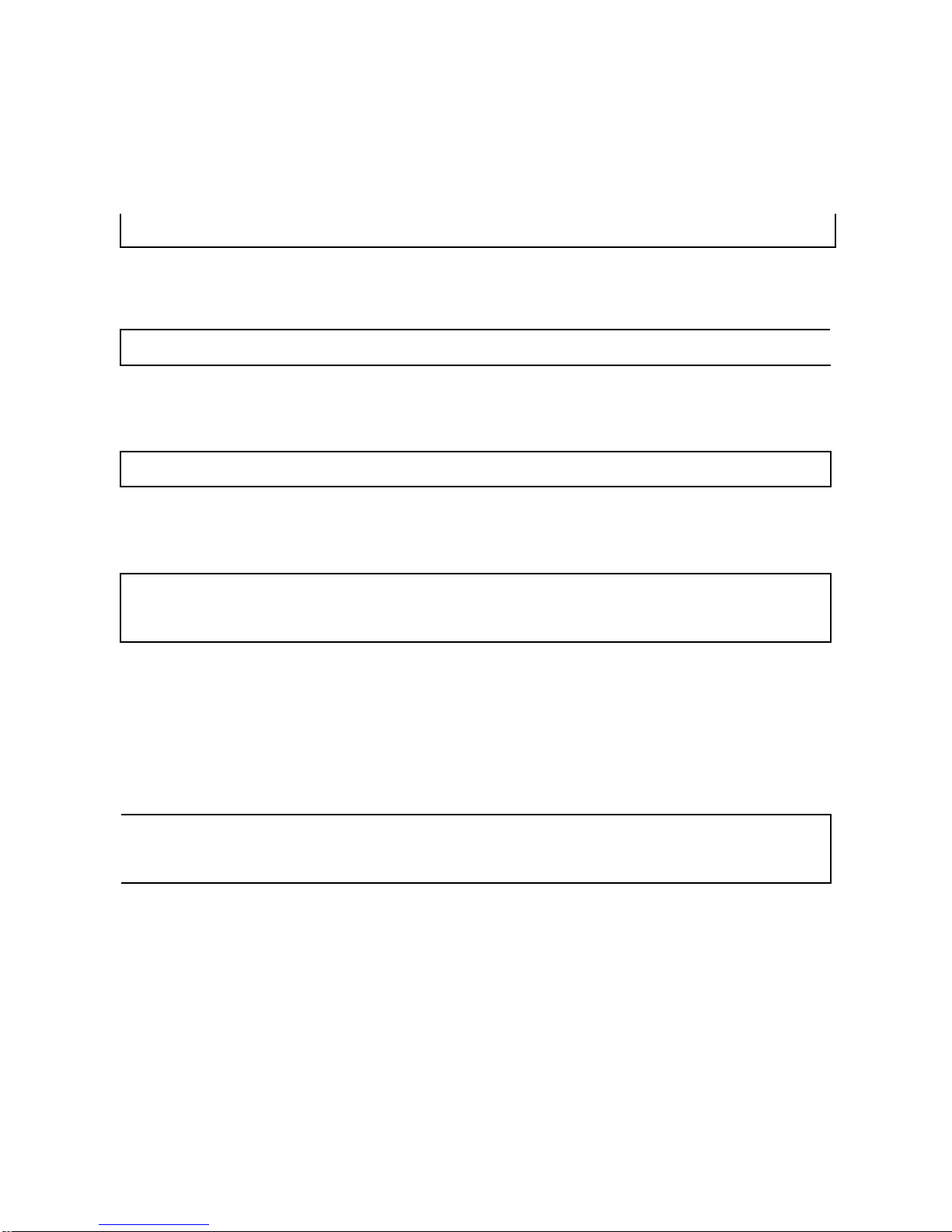
Injectors
The injectors should be removed once a
season and taken to a diesel shop for
cleaning and checking of the spray pattern,
opening pressure and for leakage. Unscrew
the delivery pipe and return pipe from the
injector. Fit protective caps. Loosen the
injector's retainer and lift out the injector. If
the injector feels stiff due to carbon buildup,
grip it with e.g. polygrip pliers and carefully
rotate it back and forth while levering it up
at the same time (with a screwdriver under
the fork), When fitting, check that the
contact surfaces between the injector and
the copper sleeve are clean. Refit and
tighten the delivery pipe and return pipe on
the injector. Make sure the cones are
properly located. Retighten both the nuts
holding the fork alternatively. For the
correct torque, refer to "Technical Data".
Start engine and check for any leakage. If
the delivery pipe has been completely
removed, vent as set out in point 4, page 2
1, to facilitate starting.
Page 23

- 21 -
CHECKS AND SERVICE
Venting of the fuel system
To enable the engine to start, the fuel system must be vented after carrying out the
following:
Change of fine filter After cleaning the feed pump strainer In the fuel tank has been
run empty When fitting an injection pump If leakage or work has been carried out on
fuel pipes After long laying up periods
Venting is carried out as follows: (Regarding location, refer to Engine Component
Guide)
Open venting screw on the fuel filter about 4 turns. Be
observant for fuel leakage.
Pump up the fuel by using the hand primer until fuel, free
from air bubbles flows out. Close venting screw. If the pump
action is poor, turn the engine so that the cam driving the
pump changes position.
If the injection pump has been removed, or when first
starting a new engine, the injection pump must be vented.
Open the venting screw on the injection pump about 2
turns. Pump the hand primer until fuel free from air bubbles
flows out. Close the venting screw.
Loosen the injector's delivery pipe nut, push in the stop
control and put the engine speed control in the full speed
position. Press down the cold start button (M D 11 C only).
Turn the engine by using the starter motor until fuel flows
out from the delivery pipes. Retighten the delivery pipe nut
and start the engine.
Page 24

- 22 -
LAYING-UP AND LAUNCHING
SERVICE IN CONNECTION WITH LAYING-UP
AND LAUNCHING THE BOAT
INHIBITING ENGINE AND REVERSE GEAR
IDLE ENGINE FOR BRIEF PERIODS WITH BOAT IN WATER
To prevent the engine from corrosion attacks, it must be run warm at least once every
14 days as long as the boat is in the water. If it is anticipated that the boat will not be
used for more than a month, long-term inhibiting should be carried out.
INHIBITING FOR A LONG PERIOD
An authorized service shop should test the engine and equipment before inhibiting
the engine for a long period according to Inhibiting Schemes I and ll. It is advisable to
test the compression to find out the condition of the engine.
INHIBITING SCHEME
Carried out with boat in water
Run the engine warm
Pump out all the oil from the engine and reverse gear
Use an oil scavenging pump
Change the oil filter. Fill the engine and reverse gear to the
correct level with Volvo Penta diesel engine oil, which also has
rustproof ing properties. The engine is thereafter ready for
operation with this oil for the next season.
For long-term inhibiting, exceeding the normal winter lay-up
period, preservative oil should be used. This should be of the
type Esso Rustban 623, Shell Ensis oil or corresponding oil. In
this case, the oil filter shall not be replaced until launching.
Drain the fuel filter and refit the holder with filter. If an extra fuel
filter with water separator is fitted, drain if there is any water in
the fuel.
Page 25
- 23 -
LAYING-UP AND LAUNCHING
INHIBITING SCHEME ll
Carried out with the boat on land
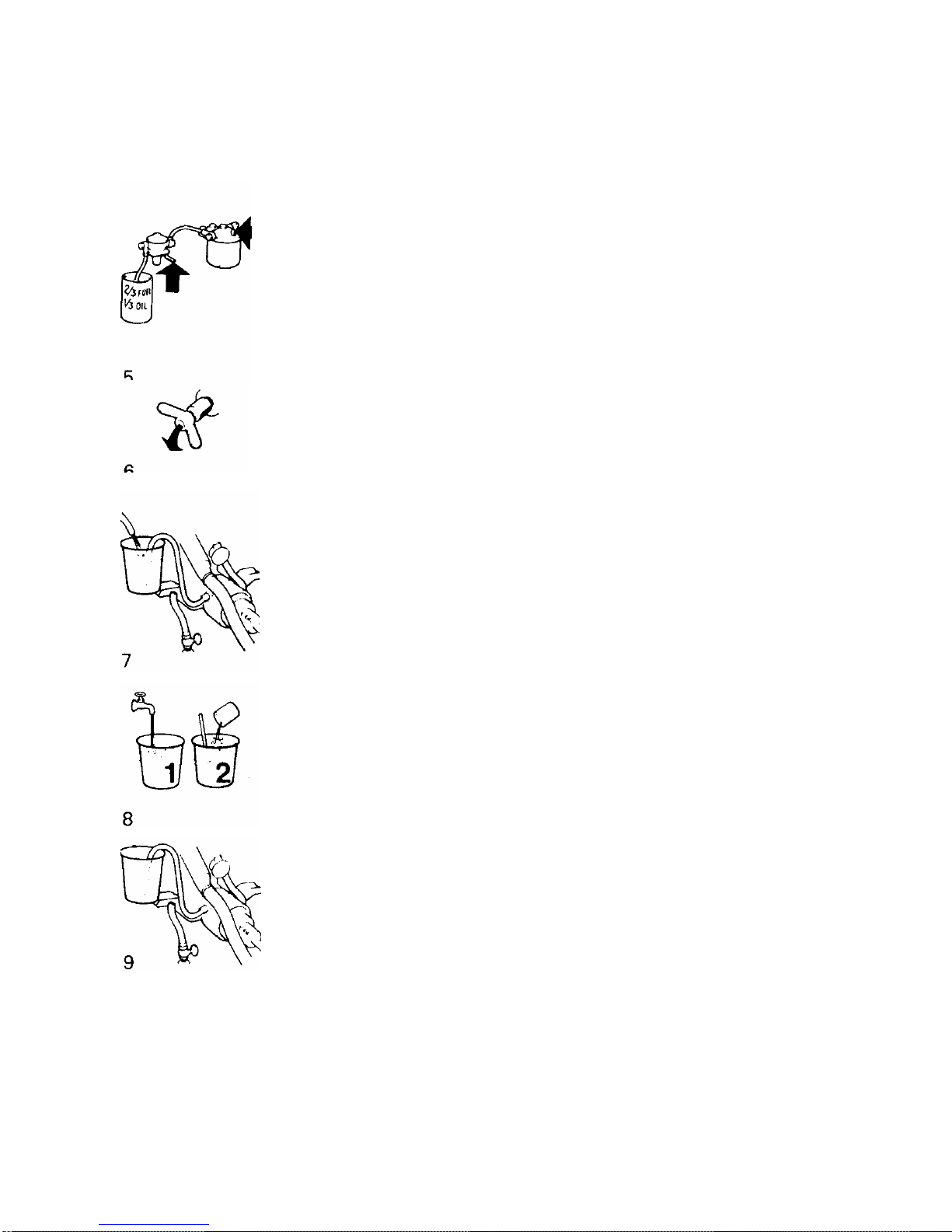
Disconnect the fuel pump's flexible suction hose from the fuel
system and insert the free end in a can filled with 1/3 Volvo Penta
diesel engine oil or preservative oil, and 2/3 diesel fuel oil. Vent
the fuel system (see page 21).
NOTE. If the fuel system has an electrically operated fuel pump, it
must be switched off.
Drain the cooling water from the engine and reverse gear (pos 14
and 10, pages 31-32). Check to make sure that the water runs out,
as impurities can block the cock. Then close all cocks and re-fit
the drain, cock in the reverse gear.
Disconnect the reverse gear suction line from the reverse gear.
Connect a hose with an inner diameter of 1/2" and insert the free
hose end into a container with fresh water. Arrange to have water
added to the container. Run the engine at idle for about 5- 10
minutes, so that it is flushed throughout with fresh water. At the
same time the fuel system will be inhibited. Check that nothing is
splashed near the exhaust outlet. Drain all water from the engine
and reverse gear. Then close all drain points.
Mix a rustproofing mixture consisting of 10 1(9 Imp. qts = 10,5 US
qts) and 1 1 (1.8 Imp. qts = 2.1 US qts) rustproofing oil of the
emulsifying type. NOTE: Water first and then the oil.
Use, e.g. Esso Cutwell 40, Shell Donax C or similar. As an
alternative, a freeze-resistant 30 % glycol mixture can be used.
Insert the hose into the rustproofing mixture. Start the engine and
let it run at idle until the mixture is finished. NOTE. The water
Pump must never be allowed to run dry.
Connect the fuel pump's flexible suction hose to the fuel system
pipe.
Page 26

- 24 -
LAYING-UP AND LAUNCHING
Since the rustproofing mixture does not provide any protection
against freezing, it must be drained from the engine and reverse
gear (pos 14 and 10, pages 31-32). Remove the cover from the
cooling water pump. Check to make sure the impeller is in good
condition. NOTE. Do not pull out the impeller if it is in good
condition.
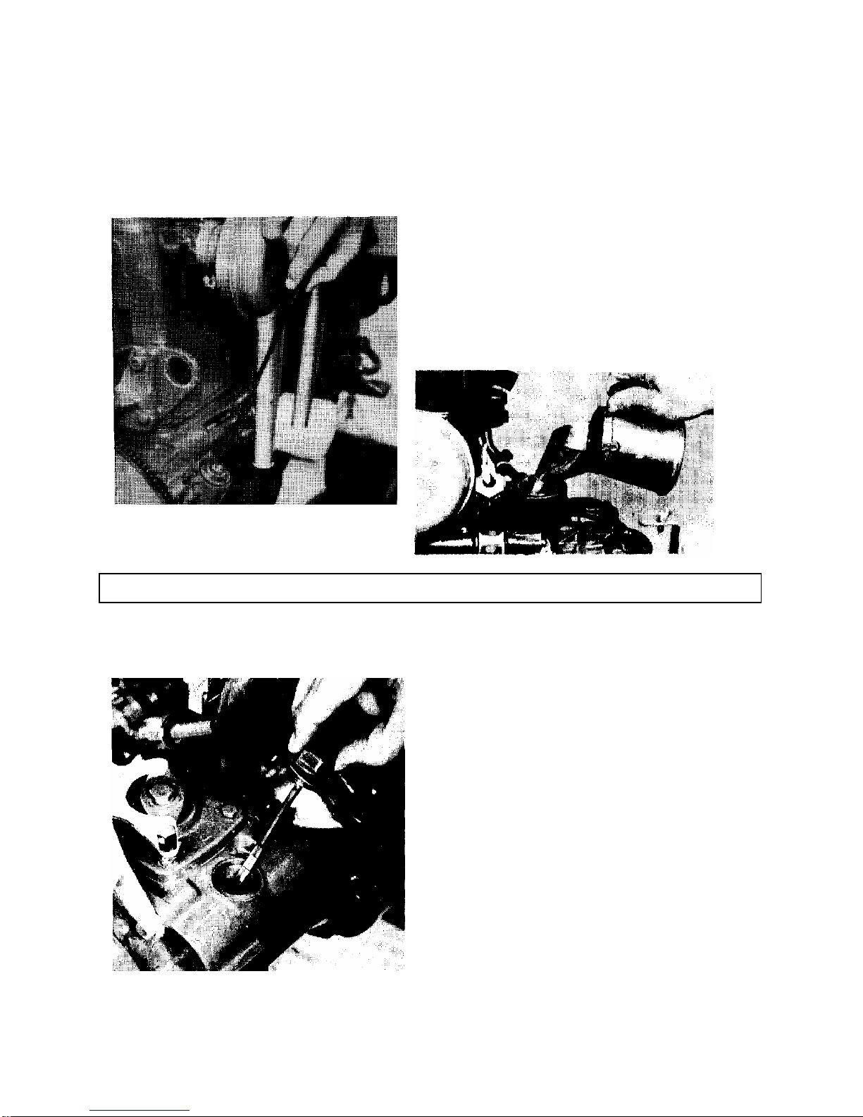
Remove the injector and hand it in to a diesel shop for cleaning and
checking. Inject Volvo Penta oil into the cylinders. Turn round the
engine several turns with the starter motor or the crank. NOTE.
Prevent oil splash. Re-fit the checked injectors, but without
tightening them altogether. They are to be removed again before
launching.
Clean the outside of engine and reverse gear. Touch in any bare
patches in the paintwork with the original type of paint. Spray the
components of the electrical system, and all the controls with
anti-moisture spray.
Remove the battery. It needs to be charged to prevent it from being
damaged.
SERVICE IN CONNECTION WITH LAUNCHING
If Volvo Penta diesel engine oil has been used, you only need to
check the oil level in the engine and reverse gear.
If preservative oil has been used, both the oil and the filter must be
replaced. See under "Service after every 50 hours of operation".
Screw tight the cover with its gasket on the cooling water pump.
Connect the hose between the cooling water intake and the reverse
gear.
Check that all hose clamps are tightened. Close the drain cocks.
Clean the outside of engine and reverse gear.
Page 27

- 25 -
LAYING-UP LAUNCHING
Install the battery, which should be fully charged. Grease the
cable shoes. Connect the battery cables. IMPORTANT. Do (not)
reverse the polarity. Tighten the cable shoes well.
Remove the injectors. Take measure to avoid oil splash and run
the engine several turns so that the oil on the piston crowns is
blow out.
Refit the injectors. See "Tightening torques", "Technical Data".
Change the fuel filter cartridge. Pump forward the fuel and vent the
system. See "Venting the fuel system" (page 21).
Launch the boat. Start the engine. See the instructions on page 5.
Run the engine warm with the reverse gear engaged. Check to
make sure there is no leakage of fuel, air, water or exhaust gases.
Check that all the controls, etc., are functioning properly.
When necessary, contact an authorized Volvo Penta Service
Shop, and let them service the engine and reverse gear according
to the instructions in the servicing scheme.
Page 28

- 26 -
FAULT FINDING SCHEME
TRACING FAULTS WITH INTERRUPTIONS IN
OPERATION
The fault tracing scheme given below lists only the most usual of faults that give rise
to interruptions in operation. With the help of the instructions given in this handbook,
the owner can generally remedy most of the faults listed below. When in doubt,
always contact the nearest Volvo Penta workshop.
Follow the maintenance scheme's recommendations - it helps provide trouble-free
operation
Engine does not start
Engine stops
Engine does not reach correct
speed at full throttle
Engine Runs Unevenly or vibrates
abnormally
Engine becomes abnormally hot
REASON See
?
Main switch not switched on, flat
battery, open circuit in electric cables or
blown fuse
pp 5, 13 17,
18
? ?
Empty fuel tank, closed fuel cock,
blocked fuel filter
pp 19, 20,
21
? ?
Water, air or impurities in fuel pp 19, 20,
21
? ?
?
Defective injector pp 20
?
?
Idling speed incorrectly adjusted pp 27
?
Boat overloaded pp 3
?
Marine growth on hull pp 3
?
Damaged propeller
?
Blockage in cooling water intake,
cooling jackets, defective impeller or
thermostat
pp 16, 17
Page 29

- 27 -
TECHNICAL DATA
Technical data
General
Engine designation MD11C MD17C
Number of cylinders 2 3
Propeller shaft output kW (hp) at 41.7 r/s (2500 rpm) 17 (23) 25 (35)
Max operating speed rev/sec (rpm) 41.7 (2500)
Cylinder diameter, mm (inches) 88,9 (3,5)
Stroke, mm (inches) 90,0(3,55)
Displacement, dm3 (in3) 1,12 (68,3) 1,68
(102,4)
Compression pressure kp/cm3 (psi) (starter motor speed) 20-24 (144-173)
Idling speed r/s (rpm) 11-13 (650-780)
Direction of rotation looking at flywheel Clockwise
Max rearwards inclination, boat underway 15°
Max sideways inclination, boat underway 15°
Engine weight, incl. reverse gear, kg (Ibs) 230 (505) 290( 640)
Valves
Valve clearance, hot engine
inlet, mm (in.) 0,30 (0.012)
exhaust mm (in.) 0,35 (0.014)
Decompression device, max downwards movement of exhaust
valve, mm (in.)
0,5 (0,0197)
Lubrication system
Engine
Oil capacity dm3 (imp qts=US qts) excl.
filter 2,6(2,2=2,7) 4,2(3,6=4,
4)
incl. filter 2,9
(2,5=3,05)
4,5
(3,8=4,7)
Oil quality Diesel lubricating oil CD
Viscosity
above +10C (50F) SAE 202
below +10C (50F) SAE 10W30
Oil pressure, hot engine, idling speed kp/cm2 (psi) 0,8-1,5 (11,2-21)
at full speed kp/cm2 (psi) 2,0-3,0 (28-42)
MSB reverse gear with reduction
Oil capacity, dm3 (Imp qts=US qts) 0,60 (0,5-0,6)
Oil quality (same as for engine) Diesel lubricating oil CD
Viscosity
above + 1° C (50°F) SAE 202
below +10° C (50°F) SAE 1OW3
Cooling system
Thermostat, starts opening at °C (°F) 60° (140°) 57° (135°)
fully open at °C (°F) 1 75° (168°) 72° (160°)
1)Propeller shaft output according to DIN Lesitung B fur Dauerbetrieb.
2) Volvo Penta CID oil, Double grade.
3) Volvo Penta CD oil, Single grade.
Page 30

- 28 -
TECHNICAL DATA
Fuel system
Injection pump, make Bosch, MD1 1 C PRF 2K 75A 407/11
MD17C PRF 3K 75A 408/11
Feed pressure, kp/cm2 (psi) 0,75 (11)
Injector, make Bosch, holder KBL 87S78/4
nozzle ....... '''' DLLA 150S720
opening pressure kp/CM2 (psi) 170-178 (2418-2531)
Pre-injection angle, crankshaft degrees B.T.D.C . 23°-26°
Reverse gear
Type Volvo Penta MSB
Ratio with reduction gear 1,91:1
Electrical system
Battery voltage, volt 12
Battery capacity, max Ah 150
Starter motor rating kW (Ah) 1,5 (2)
Alternator rating W (A) 35 (420)
Battery electrolyte spec.grav.
Charging to be carried out at g/cm3 1,230
Fully charged battery g/cm3 1,275-1,285
Torques
Cylinder head bolts
kpm (lbf) (spanner width 19 mm) 11,0 (79)
kpm (Ibf) (spanner width 15 mm) 4,5 (32)
Connecting rod bolts, kpm (Ibft) 6,5 (46)
Crankshaft main bearing (centre bearing) kpm (lbft) 8,0 (58)
Injectors nuts, kpm (lbft) 2,0 (14)
Page 31

- 29 -
WIRING DIAGRAM
Cable colour code
Mark. Colour MM2 AWG
A White 6 9
8 Black 1,5 15
B Black 0,6 19
C Red 6 9
C' Red 35 1
C" Red 0,6 19
C' " Red 2,5 13
D Grey 1,5 15
F Yellow 1,5 15
G Brown 1,5 15
H Blue 4 11
H' Blue 35 1
H" Blue 1,5 15
J Green 1,5 15
J' Green 0,6 19
List of components
1 Temperature gauge 9. Starter motor
2. Rev counter 10. Alternator
3. Battery charging warning lamp 11. Fuse box
4. Low oil pressure warning lamp 12. Main switch
5. Key switch 13. Sender, rev counter
6. Switch, instrument panel illumination 14. Sender, oil pressure
7. Switch, extra equipment 15. Sender, temp gauge
8. Connector 16. Battery
Page 32

- 30 -
ON BOARD DATA
LOA m ( ft.). Beam = m ( ft.). Draught
m ft.). Height above waterlines m
ft.). Displacement = Fuel tank cap. = I
Imp.gals. = US gals.). Water tank = I
Imp.gals. = US gals.). Battery cap., std. circuits
Ah. Battery cap., opt. equipment circuit Ah.
The light bulbs have the following wattage:
Instruments: W. Cabin: W. Pentry: W.Toi
let: W. Compass: W. Ports. Starboard lights: W.
Stern lights: W. Masthead lights: W. Searchlight: W.
Cockpit: W.
The tool kit and the spare parts kit contain the following:
. ....................................................................................
. ....................................................................................
. ....................................................................................
. ....................................................................................
I
CHECKS AND SERVICE HAVE BEEN CARRIED OUT AS
FOLLOWS:
50 hour intervalts 100 hour intervals
dat / by dat / by
dat / by dat / by
dat / by dat / by
dat / by dat / by
dat / by dat / by
dat / by dat / by
dat / by dat / by
dat / by dat / by
dat / by dat / by
dat / by dat / by
Page 33

- 31 -
ENGINE COMPONENT GUIDE
MD 11 C, Reverse gear MSB
1. Venting screw, fine
filter
2. Fine filter
3. Fuel pump
4. Oil filler, engine
5. Cold start button
(MD 11 C)
6. Venting screw,
injection pump
7. Injector
8. Injector pipe nut
9. Thermostat housing
10. Cooling water
drain plug, reverse
gear
11. Cooling water inlet
12. Cooling water
pump cover
13. Oil dipstick and oil
filler reverse gear
14. Cooling water
drain cocks for
engine (3 on
MD11C, 4 on
MD17C
15. Fuse box
16. Decompression
lever
17. Air filter and inlet
silencer
18. Hand starter (not
standard on
MD17C)
19. Oil filter
20. Fuel pump (with
hand primer)
21. Oil dipstick,
engine
22. Oil drain plug,
reverse gear
23. Sender,
temperature meter
24. Sender, rev
counter
25. Sender, low oil
pressure
26. Stop device
Page 34

- 32 -
ENGINE COMPONENT GUIDE
MD17C, Reverse gear MSB
For position explanation, refer to page 31
Page 35

- 33 -
ENGINE COMPONENT GUIDE
MD11C/110S
1. Zinc anode
2. Bracket for control
cable
3. Lever for gear
change
4. Water cooled
exhaust elbow
5. Injection pump
6. Alternator
7. Rubber engine
suspension
8. Starter motor
9. Sea water pump
10. Decompression
handle
11. Air filter with inlet
silencer
12. Oil filler
13. Fuel filter
14. Fuel pump
15. Seal between bed and
drive
16. Oil filter
17. Engine bed
18. Cooling water intakes
19. Cock for incoming
cooling water
20. Fuse box
Page 36

- 34 -
ENGINE COMPONENT GUIDE
MD17C/110S
For position explanation refer to page 33
Page 37

- 35 -
TECHNICAL DESCRIPTION
S-drive 11 0S
1. Coupling claw with rubber
coupling
2. Oil dipstick
3. Upper gear housing
4. Clutch cone, silent shift
5. Rubber suspension
6. Lower gear housing
7. Propeller shaft with helical
gears
8. Water intake for engines
cooling system
9. Rubber membrane between
drive and hull
MD1 1C/110S - MD17C/110S
The following supplementary instructions cover the description and maintenance of
the S-drive 11 0S also the equipment components and data which differ between the
reverse gear equipped engine and the engine equipped with the sailboats drive.
For maintenance and description of the engine, the previous information should be
followed.
Page 38

- 36 -
CHECKS AND SERVICE
OIL LEVEL IN DRIVE
Check every 14 days that the oil level is
within the dipstick's markings.
The oil dipstick has a bajonet fitting,
therefore it must be turned when lifting
and replacing. Note the sealing ring on
the dipstick. When checking the oil level
the dipstick must be turned to the locked
position.
Oil filling is done through the hole for the
dipstick. NOTE. Do not overfill.
Regarding choice of oil, refer to
"Technical Data" page 37.
CHANGING DRIVE'S OIL
Remove the oil dipstick. Unscrew the
drain plug under the propeller gear
housing and let the oil drain off. Refit the
drain plug together with 0-ring. Fill with oil
through the dipstick's hole. NOTE. Do not
overfill. Regarding choice of oil, refer to
"Technical Data" page 37.
ZINC ANODE
Change the zinc anode if it has corroded
by more than 50 %. Remove the
propeller and spacer ring together with
the deflector and remove the two allen
screws holding the zinc anode. Scrape
the contact surface of the drive and fit a
new zinc anode. Make sure that there is
a good metallic contact between the zinc
anode and the drive. NOTE. The zinc
anode must not be painted.
Page 39

- 37 -
CHECKS AND SERVICE
COOLING SYSTEM
The cooling water intake for the engine's
cooling is located in the drives' lower gear
housing. Check when the boat is taken up
on land, that the grill and the round hole on
the front of the drive is free from marine
growth. If there is a danger of freezing and
when inhibiting, the cooling water is drained
from the drive and the pump by the cock on
the drive. NOTE. When draining while the
boat is still afloat, the cock must be first
closed. Do not forget to open the cock
before the engine is restarted.
GENERAL MAINTENANCE
While the boat is ashore, check the drive's paintwork and if necessary touch it with
genuine Volvo Penta paint. Paint the drive with anti-fouling paint which does not
contain copper. Check from outside that the rubber membrane over the drive's hull
aperture is in place.
Check from inside that the rubber seal between the bed and the drive is not
damaged. A damaged seal must be replaced.
RUNNING Important!
When charging from engine power to sail the propeller's rotation is stopped by
engaging reverse. During sailing the control shall be in the Neutral or Reverse
position, if a folding propeller is used. The control shall be in the Neutral position if a
fixed propeller is fitted.
TECHNICAL DATA, S-drive 1 10S
Sailboats drive, type ...............................................................I ........................110S
Ratio ..............................................................................................................1.66:1
Oil capacity, sailboat drive, dm3 (Imp qts = US qts) ..............................1,8 (1,62-1,9)
Oil quality (same as engine) ..................................................Diesel lubricating oil CD
Viscosity .................................................................................................SAE 20W1)
Total weight, MD11C/110S kg (lbs) ............................................................247 (545)
MD17C/110S kg (Ibs) ................................................................................317 (695)
1) Volvo Penta CD oil, Double grade
Page 40

- 38 -
ALPHABETICAL INDEX
Alternator 1
7, 18
Launching
24
Lubricating oil
3
Battery
13, 19
Lubrication system
8
Belt tensioning 13, 16
Main switch
5, 17
Charging regulator 7, 18
Check and service sheme
11
Oil change
13, 14
Controls
2
Oil dlipstick engine
12
Cooling system
9, 16
Oil dipstick, reverse gear
12
Cylinder head bolts
16
Oil filter
15
Oil level check
12
Decompression levers 31, 3
De-inhibiting
24
Preparations before starting
4
Drain cocks
31, 32
Reserve battery
16
Reverse gear
9
Electrical system
8, 17, 29
Running
6
Engine assembly 8
Engine component guide 31-
34
Safety equipment
4
Engine speed
3
Sail drive 110S 37-
37
Sea water pump
17
Fault tracing scheme
26
Starter motor
18
Fine filter
19, 21, 31
Starting
5
Fuel 3
Fuel filters
19
Technical data
27, 28
Fuel pump
20
Thermostat
31, 32
Fuse box 18
Valve clearances
14
Hand primer 20, 31, 32 Venting the fuel system
21
Hand starter 5
Wiring diagrams
29
Impeller 17
Inhibiting 22-25
Injectors - 20
Instruments 2
NOTES
Page 41

- 39 -
Publ, no 3386
10. 77
Supplement to instruction book
MD5A, MD7A, MD1 1C, MD17C
Folding propellers are being used more and more on sailboats. There are several makes to
choose from for conventional installation.
The most important advantage with a folding propeller is that it gives less current resistance
during sailing but when the engine is running it has a somewhat lower effect especially when
manoeuvering astern.
If the boat is supplied with a folding propeller it is important to know about and observe the
following:
Putting in "FORWARD" should take place during idling. Changing at higher r.p.m. can damage
the propeller because of the great stress resulting when the blades are folded out.
When the boat is to be laid up the propeller should be treated as follows:
Clean the propeller with fresh water, remove the screws for the propeller blades' suspension
pins, take away the pins and the blades. Clean all surfaces and then lubricate all the propeller
parts with grease. Take special care with the bearing surfaces on pins and blades. Protect the
propeller boss.
When launching:
Fit the propeller together, wipe off superfluous grease and check that the blades fold inwards
and outwards easily.
Page 42

- 40 -
NOTES
Page 43

- 41 -
Personal details
Name ......................................................................
Address ..................................................................
Telephone …..………………………….....................
Nearest Volvo Penta service workshop
Name ......................................................................
Address ...................................................................
Telephone ...............................................................
Engine details
Engine type ..............................................................
Engine no . ................................................................
Reverse gear type ……..........Ratio ………………….
Reverse gear, or S-drive, serial no ...........................
Propellersize ....................................................................
Page 44

- 42 -
Publ. No. 3167
July 1976
AB VOLVO PENTA,
S-405 08 GOTHENBURG SWEDEN
 Loading...