

Page 1
Publ. No. 2505 B
Feb.1914
instruction
marine
carburetor
bool<
engine
MB
1OA
Page 2
FOREWORD
you
Before
read
and
service
The
dependabi
extent
the instructions
Volvo Penta
with
Always
and
also
We
are
outstanding
such as this
with
start using
instruction
this
your
engine
lity
on how
specially trained
fully
lonq
a
has built
contact
you rsqLrile
when
convinced
performance
will
period
these units
included
your
be
of
GUARANTEE
Each
engine is
purchaser
guarantee
caref
u I ly.
This certificate
boatbu
i lder.
guarantee
lf our
checking
engine
and its equipment
instructions
authorized
accompanied
guarantee
to a
is
shown in the
contains
is
procedures
in this
dealer.
ln all correspondence
state the type
front
of
designation
engine).
your
new
Volvo
book
carefully. lt
in
the best
and the lifetime
given
are
ln
this
book.
a world wide
personnel
nearest Volvo Penta
se'vice or
that
you
more
than
faithf
ul
your
at
the
demands concerning
have
satisfied and that
service.
by a warranty
concerning
warranty
report
forms
valid,
to be
in the
book. when
with
we make one
maintenance
are
always looked
in
your
dealer and
and serial number
Penta
marine
contains
possible
your
of
service and
service organization
service.
pdrts.
every right
all the instructions
way.
engine
and equipment
maintenance.
representative
to make
your
certificate
both materials
card
and we recommend
which
are filled
absolute condition
scheme are
after
doubt,
please
always
also
when ordering
of
the engine
engine,
including
should
good
on
Volvo
we
Always
running
high
a
Penta
which entitles
and Iabour.
in
by the
carried out
in accordance
contact
and reverse
recommend
you
depend
service workshops
you
quallty
will
you
need
to
to a
closely fol
need
advice
economy
product
provide you
run
great
low
and
the first
The extent
you
dealer and/or
and that is that the
and
a Volvo
spare
to
that
with
parts,
gear
of
read
penta
always
the
this
your
the
(see
to
CONTENTS
Presentation
Running
I nstru mentation and
GENERAL
Fuel
R un ni
Recommended
Precautions to
RUNNING
Procedure
Starti
Stopping
the unit
INSTRUCTIONS
lubricating
and
ng-i n
beforestartinS
ng
controls
oil
engine
speed
taken in case
be
recommendations
of frost
. . . .
4
4
4
.
5
5
5
o
Technical description
Engine unit . .
Lubricating system
Fuel
system
Cooling system
Electrical
Wiring diagram
Reverse and
system
reduction
gear
.
7
1
7
8
a
I
10
Servicing
Maintenancescheme
Periodical
General
Technical Data
servicing
servicing
instructions
......
.11
12-16
17-24
25-26
Tracing
faults in case
of running
interruptions
..27
Page 3
PRESENTATION
RUNNING
THE UNIT
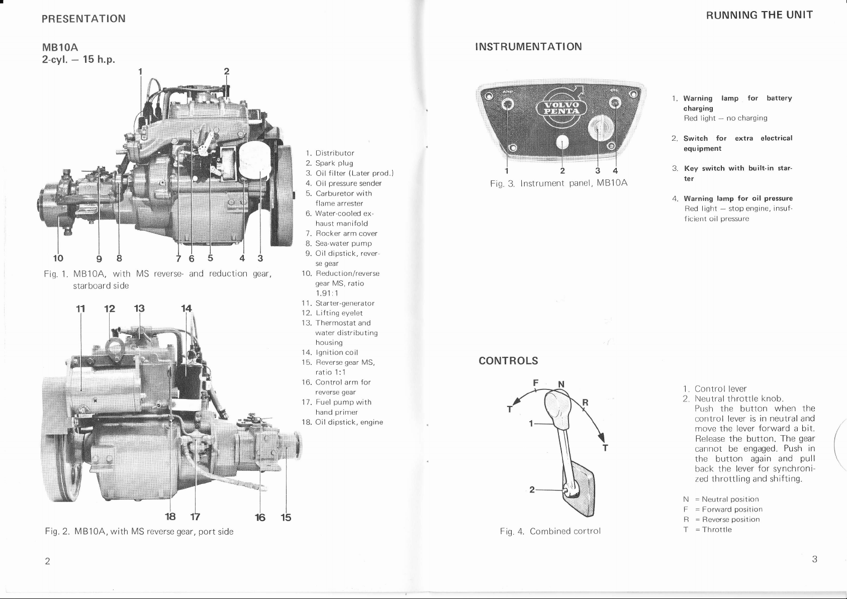
MBlOA
2-cvl.
Fig.
1.
15 h.p.
-
MB10A, with
starboard
side
MS reverse- and
reduction
gear,
1. Distributor
2. Spark
3.
4.
5. Carburetor
6.
plug
Oilfilter
Oil
(Later
pressure
sender
with
flame
arrester
Water-cooled ex-
haust manifold
7. Rocker arm cover
gear
l\,4S. ratio
1
I
pump
primer
gear
1
gear
pump
MS,
with
engine
B. Sea-water
Oil dipstick, rever-
9.
se
1 0. Reduction/reverse
gear
1.91 : 1
1 1.
Starter-generator
1 2. Lifting eyelet
1 3. Thermostat and
water distributing
housing
14. lgnition coil
Reverse
1 5.
ratio
16. Control arm for
reverse
Fuel
17.
hand
18. Oil dipstick,
prod.)
INSTRUMENTATION
Fig.3.
lnstrument
CONTROLS
panel,
MB10A
1. Warning
charging
light
Red
2.
Switch
equ
for extra electrical
ipment
3. Key switch
ter
4. Warning
Red light - stop
ficient
lamp for oil
oil
1. Control Iever
l\eutral
2.
Push
control lever is
move the lever
Release the
cannot be
the button
back the
zed
throttling
lamp f
or
charging
no
-
with built-in star-
engine, insuf-
pressure
throttle
knob.
the button
in neutral and
forward
button.
engaged.
again and
for
lever
and shifting.
battery
pressure
when
The
Push in
synchroni-
a
the
bit.
gear
pull
Fig.
2
MB10A,
2.
with MS
reverse
gear, port
side
Fig
4. Combined
cortrol
N
F
R
T
Neutral
=
Forward
-
Reverse
=
Throttle
=
position
posltion
position
.J
Page 4
RUNNING
THE UNIT
RUNNING
THE
UNIT
GENERAL
FUEL AND LUBRICATING
NOTE.
I u bricating
quality
Fuel
The engine is intended to
(Research
ROT
Lubricating
Only
Multigrade
be used
ensure
of operations.
guarantee
Our
recommendations
oi I
Method).
oil
only applies on condition
be
quality
oil SAE 1O
for
lubricating
maximum lifetime for
the engine and reverse
run on
W30
the engine
RUNNING.IN
your
When
amount of care
subject the engine to full
period
this
marine engine
during the first
that
the moving
is new, we recommend
loading for more
parts
Oil changes
During
changed more frequently
oil
the running-in
filter
after 20 hours of operation, see also under
RECOMMENDED
your
lf
propeller
the
loaded
boat. See under
NOTE.
engine
When the
speed can decrease if there is marine
therefore
regular
intervals.
1)
Previous
get
are
to
is
anti-fouling bottom
designation
period,
ENGINE
the very best
selected so
"Technical
has
boat
"For
the engine
than
that maximum engine
been in
paint.
Service
INSTRUCTIONS
OIL RECOMMENDATIONS
that the following fuel
are f ol lowed :
petrol
with
an octane
quality
with
and
designation
gear.
This oil contains additives
gear
reverse
that
20 hours of operation.
than
brief
wear in together.
reverse
and
usual. Change the engine oil, reverse
"Servicing",
SPEED
performance
Data".
the
water
growth
Check and clean the
MS".
from
for
your
speed
some
on
rating of minimum
"For
Service SE"1)
under different conditions
you
run
During this
periods,
gear
considerable time, maximum
the bottom of the boat. Use
because
lubricating oilshould be
points
boat, it is important that
reached
is
bottom of the boat at
and
is to
which
it with a
certain
time, never
is
it
during
gear
oil and the
4.
3 and
with a normally
B0
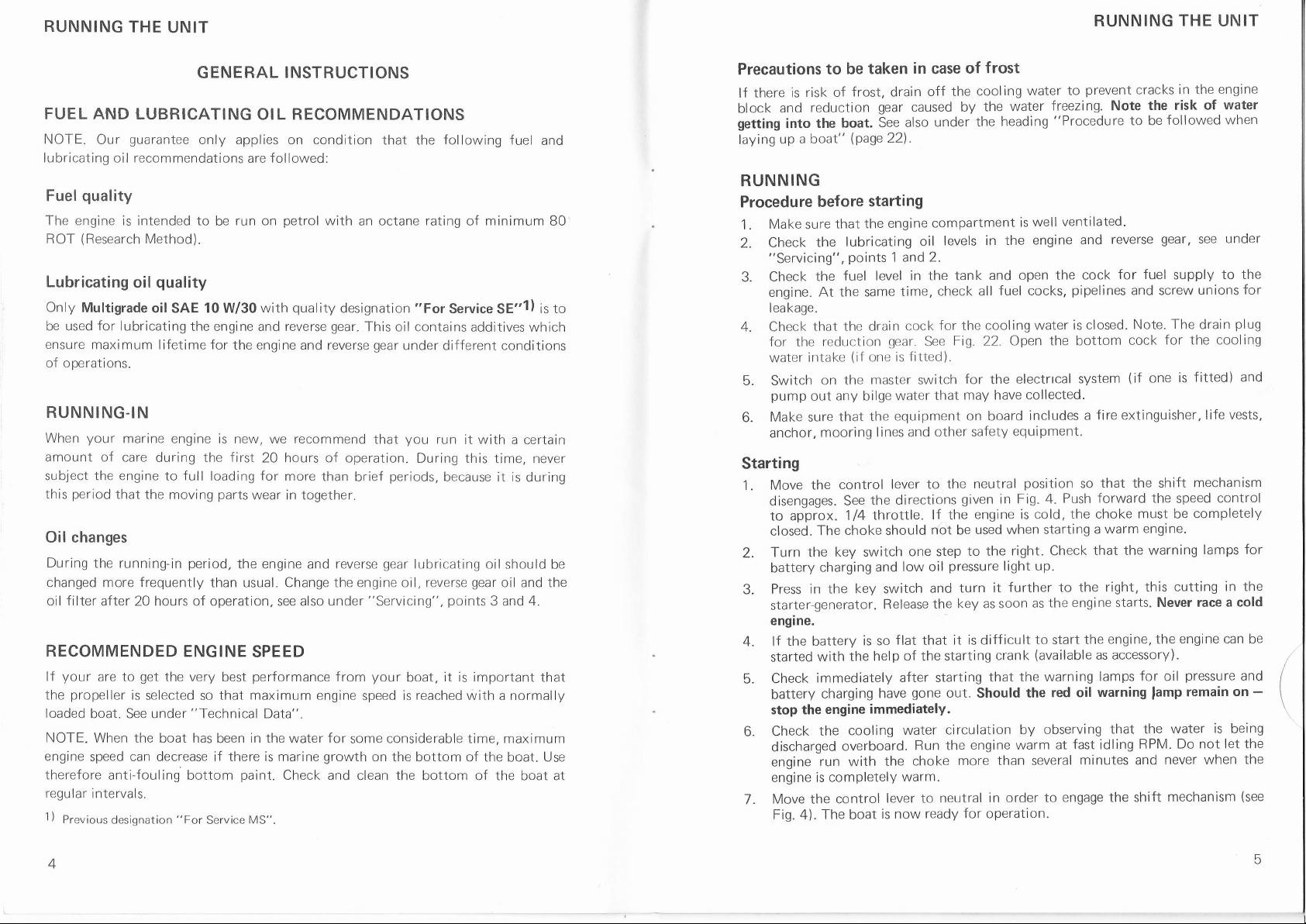
Precautions
risk of
lf there
block
getting
laying
is
and
into
up
a boat"
reduction
the boat.
RUNNING
Procedu
1 .
2.
3.
4.
re bef ore
Make
sure
the
check
"Servicing",
the
Check
engine-
leakage.
Check
At the same
that the drain
for the
intake
water
5. Switch
pump
out
Make sure
6.
anchor,
Starting
the control
Move
1.
disengages.
approx.
to
2.
3.
4. lf
5.
6.
1.
The
closed.
Turn the
battery
Press
starter-generator.
engine.
charging and
in the key switch
the battery
with
started
immediately
Check
battery
stop the
Check
discharged
engine
engine is completely
the
run with
Move the
Fig. 4).
taken
to be
frost, drain
(Page22).
starting
that the
lubricating
points
fuel level
reduction
(if
one is
on the
mooring
master
any
bilge
the
that
the directions
See
1/4
choke should
key
switch
is so
the
charging
engine
immediatelY.
cooling
overboard.
control
The
boat
in
case
of
off the
gear
See
engine
1 and
caused
also
by
under
compartment
levels in
oil
2.
in the tank
check all
time,
for the
cock
gear.
Fig. 22. Open
See
fitted).
for
switch
that may
water
equipment on board
to the
lever
not
one step
low oil
and
flat that
other safety
given
lf the
be
to the
pressure
turn it
key as soon
the
it is difficult
starting
lines and
throttle.
Release
help of the
after starting
gone
water
Run the
choke
warm.
out.
circulation by
more than several
for operation.
have
the
lever to neutral
is now ready
frost
cooling
the
neutral
engine is cold,
used when starting
Should
engine warm
water to
well
is
engine and
the
freezing. Note
"Procedure
ventilated'
the cock
the water
heading
and open
fuel cocks,
cooling water is
the bottom
electrrcal
the
have collected.
includes
equipment.
position
Push
Fig.
in
4.
right. Check
light up.
further to
the
as
to
start
(available
crank
the warning
that
red oil warning
the
observing
at
in order
to engage the
the choke
prevent
cracks in the
the risk
followed
to be
fuel
for
and screw
Note.
cock
(if
one
gear,
supply to
The
for the cooling
reverse
pipelines
closed.
system
fire extinguisher,
a
that the shift
so
forward the
must
be
a warm
engine.
that the warning
starts.
engine,
lamps
that the
idling
shift
this cutting
Never race
the
for oil
lamp
water
RPM.
mechanlsm
the right,
engine
the
as accessory).
fast
minutes and never
engine
of water
when
under
see
the
for
unions
plug
drain
fitted) and
is
life vests,
mechanism
control
speed
completely
lamps for
in the
a
cold
engine can
pressure
remain
Do not let the
and
on
is
being
when the
(see
be
-
4
Page 5
RUNNING THE UNIT
Stopping
idle
position
position
and let the engine
when the engine has
off before the engine has completely
(if
fitted)
and close
for
some considerable time.
for
more than two weeks,
(see
under
Move the control
1.
at idling
Turn the key
2.
The
stopped.
3. Switch
cocks if the unit is to remain idle
lf
4.
measures must be taken with the engine
remain idle").
speed before stopping it.
master switch must never be switched
off
the unit is
lever to neutral
switch
master
the
to remain
to neutral
switch
lf the engine has electrical equipment, this equipment
regularly
with
f luid which
protects
agalnst corrosion and moisture.
fuel
the
"Procedure
run
stopped.
and
special
some
cooling
inhibiting
if
unit is to
minutes
NOTE.
water
should be sprayed
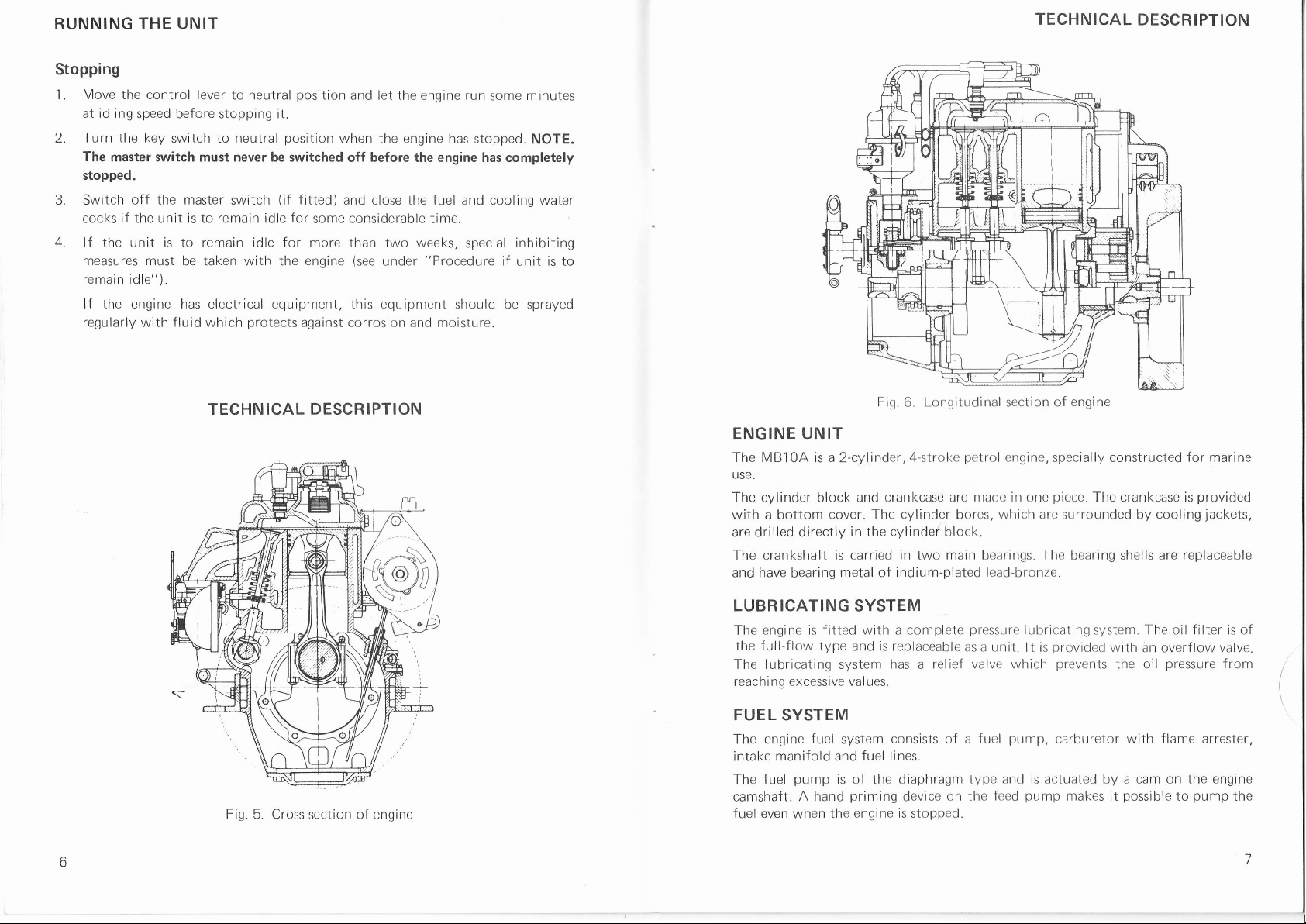
TECHNICAL
DESCRIPTION
TECHNICAL DESCRIPTION
Fig.
5. Cross-section
of
engine
ENGINE UNIT
The MBl0A is a
use.
The
cylinder block
with a bottom
are drilled directly
The crankshaft is
and have
bearing
LUBRICATING
The engine is
the full-flow
2-cylinder,4-stroke
and crankcase are made in one
cover. The cylinder
in the
carried in
metal of
SYSTEM
fitted
with a complete
type and is replaceable
The lubricating system
g
reachi n
excessive val ues.
FUEL SYSTEM
The engine
intake manifold and
The fuel
camshaft. A hand
fuel even when
fuel
system
fuel lines.
pump
is of the diaphragm
priming
the engine is stopped.
Fig.
Longitudinal section of
6.
petrol
engine,
which are
bores,
cylinder
indium-plated lead-bronze.
has
consists of a
block.
main
two
relief valve which
a
bearings.
pressure
as a unit.
pump,
fuel
type and is actuated
device
on the
feed
engine
specially constructed
piece.
The
surrounded
The
bearing shells are
lubricating
lt is
system.
provided
prevents
carburetor
with an overf low valve.
the oil
by
pump
makes it
for
marine
crankcase is
by cooling
The oil filter is of
with
a cam on the engine
possible
provided
replaceable
pressure
flame
pump
to
jackets,
from
arrester,
the
Page 6

TECHNICAL DESCRIPTION
TECHNICAL
DESCRIPTION
COOLING
engine and
The
thermoitat
is taken
The
of
the
the
On
thermostat.
manifold
thermostat
on to
conveyed
i nsta I led.
The
causes
cooling
the
irrespective
care of by
pump
neoprene
sea through
exhaust
top of
are
the water-cooled
cooling water
the thermostat
channels before
cooling water
SYSTEM
reduction
controls
which
is
driven
rubber
means
from the
and
the
manifold
engine
the
When the
filled with
is closed,
overboard,
circulation
size
of the
gear
are sea-water
temperature
the
of
sea-water
a
camshaft
operates
water intake.
ing
cool
there
engine
iackets
is a water
is cold,
cooling water
the surplus
exhaust
depending
engine
in the
to open
it enters
so
engine
of the
cooled
of the
pump
through
cam.
The
and
a
water
fi
lls
is then
the
against
distributing
the cooling
which
passes
water
elbow
where
whether
on
cooling channels
force the
and
exhaust
the
that
the
load.
engine always
the system
and
engine"
mounted
flange.
a
The
Cooling
on
The
pumpsucks cooling water
forced under
water
engine
housing
channels
is
through
in the
rapidly
the distributing
it mixes with
a wet or dry
rapidly
is
cooling
water to
water circulation
timing
the
pump
pressure
channels.
provided
engine and
heated up.
exhaust
the
exhaust line
heated up and
elbow. Thethermostat
the right
has
fitted with a
is
gear
housing.
ler is made
impel
through
exhaust
when the
housing
gases
has been
pass
the
thus regulates
temperature
from
with
and
or
this
engine
Warning!
following
The
Never break the circuit between the alternator and
is running. To
Do not
a
is
under
Wiring diagram,
Cable marking
switch off
"Servicing",
Mark Colour sq.mm.
Black i.5
Black 2.5
lvory i.5
lvory 6
Red 2.5
Red
6
Red 16
Brown 1.5
Green 1.5
Blue 1-5
to
applies
engine fitted
an
with alternator and master
battery while
this would be to ruin the charging regulator immediately.
do
the master switch until the engine has
point
16.
stopped. See
MB10A
I N5IRUMENI
IN5TRUiltNT
AWG
15
13
15
o
13
I
5
15
t5
4E
switch:
the engine
also
Fig.
7. Setting
The
A
= Setting
B
Setting
=
ELECTRICAL
electrical
The
USC.
engine is
The
starter
equipped with a starter-generator,
motor are combined
I
A
the two-way
can be
cock
with
SYSTEM
system
locked in
with drY
wet
voltage
has a
and
for outgoing
cock
the
exhaust
exhaust
of 12
are driven
desired
line
line
volts and
by
cooling water
position
is
which
vee-belts
B
a screw, see
with
designed
means
from the engine
specially
that
the
arrows
for marine
generator
f
lywheel.
and
Components
1. Key switch
2. Warning lamp f or
3. Battery
charging warning lamp
4. Switch {extra)
5. Connection terminal
6. Connection
terminal
l. Battery
"low
oil
pressure'
Fiq.8.
Wiring diagram,
BA starter
Sl
8.
9.
10.
11.
12.
13.
14.
generator.
Master
switch
Starter-generator
Charging
Fuse
pressure
Oil
lgnition coil
Distributor
MBl0Awith
regulator
sensor
I
Page 7

TECHNICAL
DESCRIPTION
PERIODICAL SERVICING
Fig
Wiring diagrams,
1.
9.
Key
ter co
starter
switch
ntact
generator
with star-
2. Extra switch
3.
Battery
4. Oil
5.
ning lamp
pressure
lamp
Connector
charging
warning
6. Connector
gear,
Reverse
The Volvo
alternative,
type Mono
Penta reverse
reduction
a
integrally built with
Power is transmitted
For manoeuvering
clutch
The
with increased
is used. With
Very
little
engaging
transmission
force
is
power
torque. The
throttling.
7. Oil
lgnitlon
8.
with Bosch
pressure
sender
coil
MB10A
9. Distributor
war
1 0.
1 1. Cable
12.
13. Charging
Starter
Fuse
generator
harness
regulator
14. Battery
15.
Shift
gear,
gear
the reverse
f rom
"Forward"
engine to reverse
the
(MS)
type Mono Shift, has a
wlth reduction ratio
gear.
"Reverse",
and
gear
the
6
through a
ratio of
1.91:1.
The
rubber f
Volvo Penta
reduction
patented
switch
Master
this type of clutch, engagement is both smooth and
required
to operate the
of the cone clutch
greater
the torque, the stiffer will be the clutch
gear.
reverse
is influenced by the size of
and, as
i:1
gear
lange.
quiet.
power
the
engagement
cone
MAINTENANCE
numbers of the servicing
The
following
the
knowledge and
out
carried
See
point
2
.t- Change oil
4.
5. Clean oil strainer
6.
1. Check vee-belts
8.
9.
'1
0. Check battery
11
12.
13. lgnition timing and distributor
14. Adjust
i5. Cooling system
i6.
11
.
is
18.
1
Or
)
2) Daily bef ore starting
Every other
3)
4) Change
by
PERIODICAL
Check oil
Check oil level in reverse
Chanqe oil in reverse
Clean air cleaner
Check valve clearances
Check and clean fuel filter
Check
GENERAL SERVICING
Check-tighten cylinder
Electrical
Check
Procedure if unit
i nhi biti ng
once each
year
the oil
SCHEME
procedures
pages.
Some
of these
the use of special
an authorized service
Operation
SERVICING
level
in engine
gear
in engine and change oil filter
and reduction
plugs
spark
head
reduction
is
remain idle and
to
level
INSTRUCTIONS
electrolyte
chanqe
and
carburetor
system
reverse and
should this occur
season
operations require specialized
tools. For this
workshop.
qear
bolts
gear
first
for f irst time
or when engine is
filter
after every 100 hours running or once each season
taken
out of boat
refer to the detailed descriptions
below
reason,
these
Every
14
days
azl
azl
o
To be carried out
according
given
vals
points
tive
necessary
operations
)
Afterl
50 hours
ru nni ng
.4)
a
a
a
a
to the inter-
under
or when
mechanical
should
Afterl)
1
hours
0O
runni
ng
3)
o
o
respect-
on
be
10
11
Page 8

PERIODICAL
SERVICING
PERIODICAL
SERVICING
1.
Checking
Check
located
is
level
above
Remove
and
Fig. 10. Checking
Fig. 10. Checking
oil
the oil
the
on
must never be
upper
the
the dipstick
viscosity, see
2.
Checking
The
level daily
located
max. min. marks
the
quality
oil
oil level
MS reverse anh
before starting
the starboard
on
level). When necessary,
oil
and
in engine
level
in the engine
level
port
side
allowed
mark since
plug
point
3.
engine oil level
engine oil level
in reverse and
reduction
on the dipstick
viscosity, see
of the
to
this
(see
for the
side of
point
daily before
engine
go
down
result in abnormally
can
Fig. 12\ to
I
reduction
gear
has a
first time
reverse
the
(which
top up
4.
starting
has upper and
and
the
below
fill
with
Fig. 11.
gear
separate oil
must
with
gear.
not
the
The
be Screwed
with new oil
for the
lower
f
irst time.
lower
mark and
markings.
high oil
oil. Concerning
Checking
1.
2.
compartment.
help of the dipstick
oil
(see
reverse
f illing
Oil
Dipstick
level should
down when
Fig. 11). Concerning
1,
The
dipstick
The oil
should
not
it
consumptlon.
quality
oil
the
gear
oil
Check the
which
between
be
measuring
level
the
the
be
oil
Change
changed.
changed
The oil
Unscrew
loosened,
screwdriver
Make sure that
filter
contact
the oil
filter is changed
rubber
with the
Tighten
idling speed
Always check
Quality
Service SEl
Previous designation
1)
Gl--
tt
æ;,"-,!'
is
filter after every
ln the case of
for the
fi
rst time after
the old
filter
use
special tensioning
a
can be used
that
the contact surface
gasket
contact surface
{ilter a further
the
checking to
while
the oil
)
a new or
fol lows:
as
(see
oil and screw
with
level
after
Viscosity
Multigrade oil
SAE 1OW/30 approx.
Service
\
I
s
(
100 hours
reconditioned
hours running
20
Fig
12bl .lf
tool or
as a lever.
against
of the
half turn but
make sure
changing
MS
$m
:&
F
å
,lk-"
::
;
running
remains firmly in
it
pierce
Remember that
the
on the
engine block.
no
there is
the oll
capacity,
Oil
Excl. oil
at the same
engine, the
"Running-in
(see
the outer
oil can spill
engine
block
fi lter
more.
by
Start
hand
no leakage at the
filter or changing
litres
filter
(1
1 .5
.3
1 .6) 1.75
=
time as the
oil filter should also be
the engine").
position
part
and cannot
the
of
out.
clean. Smear the
is
just
until it
engine and
the
filter.
engine oil.
the
(lmp.
qts.
=
filter
lncl.
I
1.85)
oil is
filter
with
comes into
run it at
qts.)
US
(1
=
55
be
a
new
3.
Changing
Change
During
Run
with the
srick
enqine
Concerning
12
the
lubricating oil
the
running-in
the
the engine warm
help
hole. The scavenging
afterremoval
the
engine oil and
after every
period
before
of a scavenging
pump
plug
of the
quality
oil
and
oil filter
50 hours
the oil should
changing
pump,
through
viscosity, see
oil.
the tube of
is supplied
which the dipstick
running
changed after 20
be
or at
The oil issucked
which
inserted
rs
with the tool
the table.
hours of
each
season.
operation.
least once
upfromthe'crankcase
see
the dip-
to
Fig. 12a.
through
kit.
is tnserted,
Oil
is added
the
Fig.
Hole for oil fi lling
12a.
Fi
g.
1 2b. Oi
I f ilter
13
Page 9

PERIODICAL
SERVICING
PERIODICAL
SERVICING
4.
reverse
Changing
Change
running or at
During
The
of an oil scavenging
to the upper
oil in
lubricating oil
the
least once
running-in
the
is drained through the
oil
pump
mark on the oil dipstick, see
each
period
oil
quality
Service SE1
Previous
1)
5.
Cleaning
An oil strainer
cleaned in white spirit
the
boat.
designation
the
oil strainer
a new
Use
is
with oil.
6.
Cleaning
The air cleaner should be
once
1.
Clean the
2.
Allow
3.
the air cleaner
each
season.
Release the lock screw
cleaner in white spirit and soak
air
engine
the
7.
Checking
Check the
due to wear or
the
vee-belts
vee-belttension afterevery 50 hours
grease.
Multigrade oil
)
SAE 1OW/30
built
at least
gasket
to run off and
oil
gear
in the reverse
season.
the oil
through
Viscosity
"Service
into the
for the
removed and cleaned
reduction
and
gear
should
reverse
gear
the hole
table below.
MS"
engine
bottom
every other
bottom
with a screwdriver
re-fit the cleaner.
gear
gear
and reduction
changed after
be
hole or is
drain
for
the dipstick.
(lmp.
litres
gear
red.
excl.
min. I
0.35
(0.31
0.37
rna*.
0.45
(0.40
=
0.48)
)
cover.
year
or when
cover and
Oil capacity
check
after every 50
20 hours of
sucked
When adding oil,
qts.
US
=
incl. red.
I
lmin. I
0.50
(o.44
=
0.53)
The oil strainer should be
the engine
for leakage after
after every 100 hours
and remove the cleaner. See
The
oil.
belts
it in engine
running.
hours
operation.
up with the help
f ill up
qts.)
gear
max.
0.60
(0.53
0.64)
is
taken
=
out of
=
filling
running,
Fig.
13.
can
start slipping
or
I
tension
Fig. 13. Cleaning
shows
Test the belt
tor and
under
an alternator
lf
possible
fa n.
lf the belt
the alternator
at
outwards and
tensioning by
flywheel. lt should
normal
thumb
get
the
to
is insufficiently
re-tigh.ten
air cleaner, arrow
lock
is
pulley
)
screwl
pressing
pressure,
fitted, the vee-belt
to slip by
tensioned,
attaching
the screws.
possible
be
Fig.
see
points.
Fig. 14. Checking
the belts
in
14.
turning with
loosen the tensioner
Tension
midway between
press
to
tension
one
the belt by
them in
should be
finger a wing on
belt
the starter-genera-
about 3-4
so hard that
well as
arm as
(1/8")
mm
is
it
the alternator
the
bolts
moving the alternator
just
8.
clearances
Ghecking
Check
each
adjustment
should
valve
the
season.
carried
be
valve clearances
engine
Concerning
wlll involve
out
valve
grinding
an authorized
by
every 100
after
clearances, see
valve stem
ends
Volvo
under
and
Penta
hours running
"Technical
and
seats
workshop'
service
or at
Data".
for this
least once
Any valve
reason
this
9.
filter
filter
that
fuel
cleaned
pump
fuel
re-fit
and
Pump
gasket
the
so that the
with clanrp
every 50 hours
after
clean and
it, with the
forward
does
fuel
remove the
fuel
with
leak. lf the
not
pump
at least once
running
pins
the hand
drive
or
cover and
facing upwards. Check
primer
pumping
cam
alters
its
filter,
fuel
carefully
and
effect is
position.
each
see
the
poor,
lf an
Checking
I
ll
The fuel
season.
Wash the outside
Fig.
packing
check
turn
1) Late
and cleaning
filter should be
Clean the
15.
and re-fit
make
to
prod.
engine a bit
type
over the
of the
the cover.
sure
provided
14
15
Page 10

PERIODICAL
SERVICING
SERVICING
extra fuel filter
should
Qrain
element
10.
be
cock in the
should
with water separator is fitted
checked for
Cleaning fuel f
any water in
bottom of the filter
changed
be
at
ilter
Checking electrolyte level
Check
between 5 and 10 mm
whenever
and cause corrosion
match
11.
Checking
Check the
electrode
type
replaced
that
also that
battery
the
necessary.
gas
since
and
spark
gap
should
gauge.
lf
the
immediately. lf
you
always
plugs
the
electrolyte level
(1
14
Never add
damage. Never check the electrolyte
formed
in
the battery cells is
changing
plug
gap
and
be 0.7
electrodes are
necessary,
get
the right
are tightened
the spark
fuel.
the
container.
least
once each
Fis.
in battery
at
and 112"1 over
much
too
plugs
wear at least
(0.028")
mm
burnt
or
clean the
type of
spark
to the correct
(Fig.
15), the
The
water can
Look out for fuel
season.
15.
fuel filter
Extra
tor
least
every 14
the
since the electrolyte
highly
after every
and this must
the insulation
plugs
plugs
torque.
days.
plates.
cell
explosive.
50 hours
be checked
damaged, the
with
with the
(See
transparent container
be removed
The level
Add
can then
level
through
splash. The filter
',*
Itlkail
with
water separa-
should
distilled water
splash out
using a lighted
by
of operation. The
by using a wire
plugs
wire
a
brush. Make
correct heat range
Technical
Data.)
the
æ., \,
\
must be
sure
and
be
GENERAL SERVICING
12.
Check-tightening
With a new
bolts
should
Concerning
Fig.
16.
13.
lgnition
All
adjusting
workshop with
is one
leads
serious
The ignition
IGNITION TIMING
The ignition
specified
flywheel
the
engine or when
should be
also be
Tightening
cylinder head bolts
re-tightened after
carried out
tightening
timing
work
the
of the most sensitive
to decreased
engine damage.
timing and the distributor
timing
the Technical
in
timing marks,
cylinder
torque, see
sequence
head bolts
the cylinder
20 hours
each
once
"Technical
for
head has
running.
season
and distributor
on the engine ignition system
equipment
special
engine
is checked
parts
output, high fuel consumption
Data On
see
required
the engine and interference
of
should be checked
only with the help of a stroboscope
pump
Fig.
the oil
'1
7.
INSTRUCTIONS
been removed, the
Check-tightening
and always
Data".
@
with
o@
o
should be
for
this
housing there
carried out by a service
purpose.
and, in the
once
cylinder head
of the bolts
torque
a
The ignition system
here immediately
each
is a notch and on
wrench.
worst cases,
season.
at the speeds
to
11
Page 11

SERVICING
SERVICING
DISTRIBUTOR
Check the contact
lock
Turn
gap,
A
correctly located vertically
are
screw
surfaces.
breaker
contacts
each other. The
the
Lubricate the
lubricating wick
the
distributor.
lnspect the distributor cap
that the center
Check
breaker
engine
the
in Fig.
gap
can be adjusted
for
the attaching
distributor
(i)
under
contact
18, which should
points
which must not
until the
over
plate
with a
rotor. Lubricate
the
for
cracks and clean all contact
stud
breaker
so
turning the
by
has
been slackened.
few
drops of
is
loose
not
0.4 mm
be
that the faces
also with oil the lubricator
and
-)
be burned on the contact
points
are
(0.016").
fixed
engine
is
not
fully
open
Make
are completely
contact
(2,
oil in the
surfaces thoroughly.
worn. See
and check the
sure that the
opposite
Fig.18),
drive shaft
(3)
under
Fig.
19.
after
14.
Adjusting
The
service
Adjusting the idling speed
1.
2.
the carburetor
carburetor should
workshop.
when the throttle
Check
of the control cable
sleeve
each
side
and
lever
Run the
Adjust
unevenly,
make sure
clearance
the
of
partly
with the control
engine warm and check
idling
the
adjust the air screw
that
according
"dice".
the connection sleeve
be checked
control
has a clearance
Adiustments
(1,
screw
point
to
1.
and adjusted
is in neutral
can be
lever.
idling
the
Fig.
(2)
when necessary.
20)
even
until
for
authorized
by an
position
of
mm
1.5
made
speed, see
\1
partly
under
116"1
running is obtained.
the control
cable has the
Penta
Volvo
that the connecting
(A,
Fig.20)
the carburetor
with
"Technical
the engine
lf
Data".
runs
Check to
proper
on
1B
Fig. 17.
Timinq
marks
Fig. 19. Distributor,
Fig. 18. Distributor, adjusting breaker
contacts
checklng contact surfaces
15.
Cooling system
cooling
The
system
The thermostat
removed.
slroLrld
can be
clrrtckr:d
lxt
insJ-rcclt:d
regularly
aftt:r thc
Fig. 20. Carburetor, Solex 26VBN2
'1
ld ling screw
.
2. Air screw
1.5 mm
housing
(1/16")
etc.
has been
A
=
for leakage, deposits,
water distributor
19
Page 12

SERVICING
SERVICING
REPLACING
pump
The
of water
pump
Close the
1.
risk
shaft
reach the
protection
Pull
2.
new impeller.
3. Fit the cover
a
Fig.21
16.
Electrical
CHECKING THE
The
state of charge of
is done by using a
this varying
CABLES AND CABLE TERMINALS
At regular
none
STARTE
All work on the
an authorized
engine
THE SEA.WATER
impeller
deficiency
impeller is changed
is made
caused by, for example,
as
bottom cock.
of water
with the
the impeller off
getting
pump
retaining
bolt
under the
into
impeller
screwdrivers in order
the shaft. Clean the inside
with its original
spare impeller on board.
Removing
.
Arrow
lock bolt
impeller.
points
to impeller
system
STATE OF CHARGE
the battery
hydrometer which
with the state of charge.
intervals check that all
of the
R-GENERATOR
given
is
is
cables
damaged.
starter-generator
service
qeneral
a
workshop.
overhaul.
PUMP IMPELLER
of neoprene rubber
fol
Remove the
the impeller.
lows:
the boat.
out of the
and this
blocking
cover
With the
housing as far
See Fig
from
can be damaged
of the
the
sea-water
help of two
as
NOTE. Place
21.
not to damage
pump
of the
gasket
which has the right
Open the bottom
OF THE BATTERY
should be checked at least once each
shows the specific
(See
cable terminals are
(and
alternator
lnspection and control
under
cock.
"Technical
fitted)
lf
thickness. Always
gravity
Data".)
properly
should be carried out by
should be done when the
in the case
sea-water inlet. The
pump.
Note the
in
some
and
season.
pullthe
order
kind
housing.
fit
have
This
screwdrivers
necessary
the impeller
housing
of the electrolyte,
tightened and that
the
NOTE. This is
The battery
grease
or
WARNING!
lf the alternator
to
of
important
Never break
1.
running. The
ru ined.
The master switch
stopped.
Never confuse
2.
stamped
earthed to
be
Use only
3.
generator.
ln the case
4.
Let
battery
englne starts
ordinary batlery.
Never use a
5.
Always disconnect
6.
alternator
electric
7. lf
disconnect
Check
8.
particularly
poles
and
vaseline.
and its regulator are
that the
following instructions
the circuit between
result will be a short-circuit
with a
the engine block.
Volvo
of
starting
ordinary battery
the
to the
disconnect
rapid charger while
equipment.
welding work
the charging
vee-belt tension and
important when
cable clamps should be
must never
the battery
plus
and a
Penta double
be switched
poles
minus sign
diode
using a spare
by
remain
ordinary battery,
the spare
the alternator
battery
both
is to be carried
regulator
cable
the engine is
well tightened and smeared
function
to
are followed:
the alternator and
in the
off before
one another.
with
respectively.
kits when charging
battery,
connected
plus
cables before
cables at
connections at
to
battery
out
plus
but never
on the engine
the alternator
fitted with an alternator.
perfectly,
battery
while the engine
regulatorwhich
the engine
poles
The
The minus
two
batteries
this should
in circuit.
minus to
and
is connected
carrying
be done
Connect
break
to
out any
the circuit to
or installation units,
and insulate.
regular intervals.
it is extremely
is immediately
has completely
generally
are
pole
must always
from one
follows:
as
the
minus. When
the battery.
work on
with
is
spare
the
the
the
17.
remote
the lock
gear
checked regularly
that there
gear.
When
control should be
nut
and turning
for
oil leakage,
no
is
gear
reverse
completely off-
the cable
constant
enga-
is
"dice".
Ghecking
reverse
The
abnormal
remote
When
pressure
ged
loaded.
on the control
"Forward"
for
Adjust if
reverse
the
gear
noise or excessive
control
gear
reduction
and
is connected,
components
"Reverse",
or
necessary by loosening
reduction
and
gear
should be
operatinq temperature.
it must be so designed
of the reverse
the
20
21
Page 13

SERVICING
SERVICING
18.
Procedure
IDLE PERIOD WITH BOAT AFLOAT
ln
case
should be
damage to
lf
the engine is to remain
should be inhibited,
Protect
spraying unpainted
protection
We also recommencl
the case
PROCEDURE
Before the boat is taken
service
compression test on the
PREPARE THE
WATEB AS
1. Run the engine
and
Fill
2.
if
unit is to remain idle
of
an idle
started and
the internal
the engine
spray.
period
see
and equipment from external
surfaces and electrical
that the
of
longer intervals of
BEFORE LAYING UP
workshop
reverse
up the engine
test the engine
ENGINE
FOLLOWS:
gear
warm,
with the
of
less than one
run
warm
parts
of
idle
"Procedure
under
cylinders are
idleness.
up on land for
engine.
FOR LAYING UP BEFORE
stop it and
help
reverse
and
dlpstick. Suitable inhibiting
corresponding oils of
another make.
3. Run the engine off-load for
after
at least every
the engine.
for
a longer
laying up, it
and reverse
pump
of
the
gear
with
oils are Esso
about
5 minutes.
with the
month
period
than one month,
before laying up"
corrosion
components with corrosion
sprayed through the
is advisable to let an
gear.
lt is also
THE BOAT IS
all the lubricating oil
scavening
pump.
inhibiting
Rust Ban
boat afloat, the engine
prevent
14 days
to
damage by regularly
spark
advisable to carry out a
LIFTED
oil to the lowest mark
623, Shell
corrosion
then
engine
the
and moisture
plug
holes in
authorized
OUT OF THE
out of the engine
on the
Ensis
Oil20
c. Disconnect
intake
disconnect the suction line between
intake
lnstead connect a
d.
sufficient
m
ixtu
the
from the
from
to
re.
suction
reduction
Lhe
reach down to the bottom
e. lnsert the connected suction
let it run at idling until the
forming a
this
protective
let the engine run dry since
Then
connect
the coolinct water
f. Drain all cooling
Fig.
22. The rustproofing mixture does not
engine is fitted with a wet exhaust line, this should also be
lf the
frost.
drained of water. When a
cooling water through the
the cooling water
Drain
S.
impeller
shaft
Remove the
over the
or
(see
remain in
spark
engine
under
position
plug
several
line
pump.
When a
112"
from
water
pump
"Servicing",
and
and spray
turns before
between
gear.
rubber
the cooling water
the
gear
reduction
reduction
hose, the
is
length of which
of the containerwith
hose into the container. Start
water has been
sucked
oil film in all the cooling channels.
this can damage the cooling water impeller.
hose.
engine
the
by opening the drain cock, see
protect
reduction
plug
re-f it the
gear
fitted, this
is
in the bottom of the reduction
removing the
by
point
each cylinder with inhibiting
re-fitting
15)
cover.
the spark
forwinter
pump
and bottom
f
itted to
gear
the reverse
and
the
rustproofing
the engine and
out of the contatner,
NOTE. Never
the engine against
should be drained
gear.
pump
cover. Take
storage.
Let
oil. Then turn
plugs.
gear,
bottom
should
out the
the drive
be
of
AFTER
PROCEDURE:
1.
THE
lnhibit
Drain off all cool
a.
opening the
by opening the
Mix rustproofing
b.
lmp.
should
Donax C or
NOTE. Always add the oil to the water and never the other way
22
BOAT HAS BEEN LIFTED
the cooling
system
as follows:
ing water
(on
cock
drain
plug,
drain
agent in a container filled
galls.
4112 US
-
be of the emulsifying type, for example, Esso
similar.
galls.)
Add
ASHORE,
from
the
starboard side) and from
Fig.
see
of fresh
rustproofing
20 %
CARRV OUT THE FOLLOWING
engine
the
Then
22.
water. The
close the cock and
oil to the water and stir well.
and exhaust manifold
the reduction
drain
with at least 20 litres
rustproofing
agent used
Cutwell 40,
gear
plug.
(3
1/2
Shell
around.
by
Fig.22.
1.
Dr,rin,.ock
Drain
2.
Drain cock
pluq
for oooling water, reduction
for
cooling water,
(
fr'r
ooling water, engine
engine
gear
LJ
Page 14

SERVICING
TECHNICAL DATA
J-
Clean the outside of the engine
paintwork.
them with
battery and
be
put
kept in
good
the rustproofing
3 and 4.
reverse
and
impeller in
connect all hoses and check-tighten
gear
the cooling water
4.
touch up
system by
Bemove
damaged
spraying
the
intervals if it ls to
PROCEDURE WHEN LAUNCHING
Pump
1.
2.
3.
4.
out
all
"Servicing",
points
Fill the engine
points
Fit
point
Clean the outside of the engine
3
the
15, and
and 4.
pump
the operating controls.
Take a
5.
NOTE.
The
Grease in the
Remove the
6.
generator
tops of the
"Technical
CIose the drain cock
gear.
Launch the
8.
pump
tank,
leakage.
Start
9.
5*6. Run the
there is
fully
charged
battery
Be careful not to confuse the
negative battery
battery
spark
pole
cable
plugs
should be
clamps with
and
turn over the engine
in order to blow out any rustproofing
pistons.
Data"
NOTE.
for
Open the bottom cock
and fill the fuel tank. Clean
boat
forward fuel with the help of
lines,
connections and cocks to be
the engine and follow carefully the
engine
no leakage
of
Prevent
their tightening torque.
for
the cooling system. Note. The
for
warm with the reverse
fuel,
water, oil, air or exhaust
it immediately. Check the bolts and nuts
10.
Contact an authorized Volvo Penta
gear
engine and
reverse
carried out as specified in the maintenance scheme.
reverse
and
Protect
corrosion and moisture
it into
gear
with white
all
unpainted
parts
protective
storage. lt must be
spirit
and the electrical
spray.
re-charged
condition.
oil from
with
the engine
and
lubricating oil,
pump,
reverse
see under
see under
gear,
the hose clamps.
and
on
reverse
board
earthed
gear
of rustproofing
and connect up the
(see
cables
grease
under
to
the engine.
or vaseline
several turns with the
battery cables.
"Servicing", point
before tightening.
oil which may be on
plugs,
spark
plug
for
(see
Check thoroughly the
that
given
lf there is,
the
oil
splash.
cooling
the hand
Re-fit the
water intake.
fuel filter
the
primer.
absolutely sure
running
for
service workshop and have servicing of the
instructions
gear
engaged. Check
gases.
tightness.
or
similar
regular
at
see unCer
"Servicing",
"Servicing",
oil and
adjust
starter-
see
reduction
the
point
9) and
there is no
on
to make
attend to
and
16).
the
under
pages
sure
General
Type desingation
Max. output,
Max. speed,
Number
Type of operation
Displacement,
Bore mm
Stroke,
Compression
Compression
ldling
Total
Max.
Valves
Valve clearances,
lnlet
Exhaust valve,
Valve
lnlet valve,
Exhaust
Reverse
Type designa
Ratio
Ralio with auxiliarV
h.p.
r.p.m.
of cylinders
(cu.
cc
(in.)
mm
speed,
weight, approx.
inclination of
valve, mm
clearances,
"Forward"
{in.)
ratio
pressure
r.p.m
mm
valve, mm
gear
t ion
. .
warm
mm
cold
and
Lubricating system
Engine
quality
Oil
V iscosity
capacity,
Oil
excl.
incl.
Oil
Reverse
Oil
Oil
Oilcapacity
1
)
Adjustment
2)
Previous
engine, litres
filter
filter
pressure,
quality/Viscosity
capacity.
warm engine,
gear
litrer
with auxiliary
is carriåd
desiqnation
in.
)
({ully
open throttle), speed,
(lb.),
kg
enqine in boat
enginel
{in.)
(in.)
i
enginel
(in.)
(in.)
"Reverse
gear
(lmp.
idling speed,
at full speed,
(lmp.
qt.
out
bv
"service
engine
underway
)
qts.
US
=
gear,
grinding
MS"
+
=
qt.)
litre
reverse
qts.),
US
tp/cm2
kp/cm2
. . .
(lmp.
valve stem
gear
approx.
qt.
kp/cm2
(p.s.i.)
{p.s.i.)
USqt.)
=
ends and
(p.s.i.)
seats
. . .
.
MBiOA
15
2000
in-line
2
Side-valve,
carburetor
1018
88.9
82
6.5:1
7.5
600
1 15
1Bo
0.30 {0.012)
o.35
0.35
0.45
Volvo Penta MS
1.1
1 91:'1
l\/lultigrade
Service SE2)
SAE
1.5
1.75
1-2
4
Same
0.4
0.55
(3.23\
1101\
(253)
(1.3
l51l
(0.35
{62.1 )
(3.50)
(0.014)
(0.014)
(0.018)
1OW/30
=
(1.55
r4-28)
as engine
=
(o.48
4-stroke
engine
oll
1.6)
=
0.42)
=
1.85)
O.5B)
14
25
Page 15

SERVICING
Fuel system
pressure,
feed
ROT,
system
Bosch type
(in.)
(in.)
(in.)
type
min.
. .
ing,
.
.
Carburetor, Solex
jet
Main
ldling
iet
Float valve
pump
Fuel
grade
Petrol
rating
Octane
lgnition
Cylinder
Spark
Early
Distributor, Bosch type
Late
Distributor, Bosch type
marking
plugs,
mm
Gap,
prod.
Basic setting
Stroboscope sett
Gap, mm
Cam angle
prod.
Basic setting
Stroboscope setting,
Gap, mm
Cam angle
Electrical system
Voltage, volts
capacity, Ah max.
Battery
capacity, Ah max.
Battery
electrolyte specif
Battery
Fully charged battery,
to be re-charged
Battery
Starter-generator,
type
Generatoroutput,W
output, h.p.
motor
starter
Starter-generator,
Generator output, W
Starter
Tightening
Cylinder bolts,
plugs,
Spark
Flywheel
Connecting
type
motor output,
torques
(lb.ft.)
kpm
kpm
{lb.ft.)
kpm
(lb.ft.)
(nut),
rod nuts, kpm
26 VBN2
102.5
45
1.2
o.2
80
1 nearest f lywheel
W175T35
correspondi ng
spark
other
0.7
kplcm2
(p.s.i.)
.
JF20231 109 014
30 after
1200
12OO
r.p.m
r.p.m.
oao
0.4
600
JF2O231 109 015
20
1 10
0.4
600
12
(SIBA
(BOSCH
gravity:
ic
9/cm3
at
iba
S
,..
STARTER
STARTER GENERATOR)
GENERATOR)
. .
g/cm3
.,.....
34
60
1.275*1 .285
1.230
DS418
60
0.8
Bosch LA/Ej
. . .
h.p.
(lb.ft.)
135
1
8.3
3.8
38
5.5
(3)
plug
make)
(0.028)
T-D.C.
(0.016)
t
30
(before
(0.016)
a
30
90/2900
max.
(60)
127.51
12151
(40)
(alt.
of
T.D.C.)
9O kont
TRACING
fault-tracing scheme
The
operation.
to trace most
nearest Volvo
Follow the
FAULTS IN CASE OF RUNNING
With the help
of the causes
Penta
service
instructions in the
reliability.
(L
o
o
Hs
o
o
c
o
.;
o
o
o
c
.E
'a
qD
uJ
u.l
X
x
X Fuel
X X X
X X
X
X
9rE
-o
os
(:€
6=
0q
OE
6F
c13
'FE
uJ
ii
X X
X
X
X X
å>
oG
=F
or
LO
øc
E-O
JO
oo
,86
På
llt
>
X
includes only the
below
of the instructions
mentioned
workshop.
servicing scheme
G
o
o
o
o
tr
'6,
ur
X
FAULT TRACING
Master
discharged
tank
fLrel f ilter blocked
Water
Faulty spark
Burnt breaker
distributor
ldling speed
Boat abnormally
Marine
Propeller damaged
Blocked cooling
or cooling
pump
INTERRUPTIONS
more usual
given
in this book
below. ln case of doubt
ensures the best
this
-
not' on: battery
switch
or broken electric cable
empty, fuel
or impurities in
plugs
points,
and ignition cables See
not
growth
iackets,
impeller or thermostat
cock closed,
fuel See
moisture in
properly
loaded See
boat bottom See
on
adjusted
water intake
defective
reasons for faulty
it is usually
possible
always contact
running
Remarks
pages
See
-21
page
See
page
page
See
page
page
See
page
page
pages
See
20
the
15
1
17
4
4
16
1
20
6
9
1
9,
,/6
27
 Loading...