

Page 1

Workshop Manual
Engine unit
MD6A, MD7A
AB Volvo Penta
Customer Support
Dept. 42200
SE-405 08 Gothenburg
Sweden
A
2 (0)
Page 2

Workshop Manual
Marine diesel engines
MD6A, MD7A
Contents
Safety Precautions 2
General information 5
Repair methods 6
Presentation
MD6A 8
MD7A 9
Repair instructions 10
Electrical system 30
Special Tools 34
Technical Data 35
1
Page 3
Safety Precautions
Introduction
This workshop manual contains technical data,
descriptions and repair instructions for Volvo Penta
products or product versions contained in the contents
list. Ensure that the correct workshop literature is being
used.
Read the safety information and the Workshop
Manual “General Information” and “Repair
Instructions” carefully before starting work.
Important
In this book and on the engine you will find the
following special warning symbols.
WARNING! If these instructions are not
followed there is a danger of personal injury,
extensive damage to the product or serious
mechanical malfunction.
IMPORTANT! Used to draw your attention to
something that can cause damage, product
malfunction or damage to property.
NOTE! Used to draw your attention to important
information that will facilitate work or operations.
Below is a summary of the risks and safety precautions
you should always observe or carry out when operating
or servicing the engine.
Immobilize the engine by turning off the power
supply to the engine at the main switch(es) and
lock it (them) in the OFF position before
starting work. Set up a warning notice at the
engine control point or helm.
Generally, all servicing should be carried out
with the engine switched off . Som e work
(carrying out certain adjustments for example)
requires the engine to be running. Approaching
a running engine is dangerous. Loose clothing
or long hair can fasten in rotating parts and
cause serious personal injury.
If working in proximity to a running engine,
careless movements or a dropped tool can
result in personal injury. Avoid burns. Take
precautions to avoid hot surfaces (exhausts,
turbochargers, charge air pipes and starter
elements, etc.) and liquids in supply lines and
hoses when the engine is running or has been
turned off immediately prior to starting work on
it. Reinstall all protective parts removed during
service operations before starting the engine.
Check that the warning information decals on
the product are always clearly visible.
Replace decals that have been damaged or
painted over.
Engine with turbocharger: Never start the engine without installing the air cleaner (ACL).
The rotating compressor in the Turbo can
cause serious personal injury. Foreign
objects entering the intake ducts can also
cause mechanical damage.
Never use start spray or similar to start the
engine. The starter element may cause an
explosion in the inlet manifold. Danger of
personal injury.
Avoid opening the filler cap for engine
coolant system (freshwater cooled engines)
when the engine is still hot. Steam or hot
coolant can spray out. Open the coolant filler
cap carefully and slowly to release pressure
before removing the cap completely. Take
great care if a cock, plug or engine coolant
line must be removed from a hot engine. It is
difficult to anticipate in which direction steam
or hot coolant can spray out.
Hot oil can cause burns. Avoid skin contact
with hot oil. Ensure that the lubrication
system is not under pressure before
commencing work on it. Never start or
operate the engine with the oil filler cap
removed, otherwise oil could be ejected.
Stop the engine and close the sea cock
before carrying out operations on the engine
cooling system.
Only start the engine in a well-ventilated
area. If operating the engine in an enclosed
space, ensure that exhaust gases and
crankcase ventilation emissions are
ventilated out of the working area.
2
Page 4

A
lways use protective goggles where there is a
danger of pieces of metal, sparks from
grinding, acid or other chemicals being thrown
into your eyes. Your eyes are very sensitive,
injury can lead to loss of sight!
Avoid skin contact with oil. Long-t erm or
repeated contact with oil can remove the
natural oils from your skin. The result can be
irritation, dry skin, eczema and other skin
problems. Used oil is more dangerous to health
than new oil. Use protective gloves and avoid
using oil-soaked clothes and rags. Wash
regularly, especially before meals. Use the
correct barrier cream to prevent dry skin and to
make cleaning your skin easier.
Most chemicals used in products (engine and
transmission oils, glycol, petrol and diesel oil)
and workshop chemicals (solvents and pa ints)
are hazardous to health Read the instructions
on the product packaging carefully! Always follow safety instructions (using breathing apparatus, protective goggles and gloves for example). Ensure that other personnel are not
unwittingly exposed to hazardous subst anc es
(by breathing them in for example). Ensure that
ventilation is good. Handle us ed and exces s
chemicals according to instructions.
Be extremely careful when tracing leaks in the
fuel system and testing fuel injection nozzles.
Use protective goggles! The jet ejected from a
fuel injection nozzle is under very high pressure, it can penetrate body tissue and cause
serious injury There is a danger of blood
poisoning.
All fuels and many chemicals are inflammable.
Ensure that a naked flame or sparks cannot ignite fuel or chemicals. Combined with air in certain ratios, petrol, some solvents and hydrogen
from batteries are easily inflammable and
explosive. Smoking is prohibited! Ensure that
ventilation is good and that the neces s ary
safety precautions have been taken before
carrying out welding or grindin g work . Alwa ys
have a fire extinguisher to hand in the
workplace.
Store oil and fuel-soaked rags and fuel and
oil filters safely. In certain conditions oilsoaked rags can spontaneously ignite. Used
fuel and oil filters are environmentally
dangerous waste and must be deposited at
an approved site for destruction together with
used lubricating oil, contaminated fuel, paint
remnants, solvent, degreasing agents and
waste from washing parts.
Never allow a naked flame or electric sparks
near the batteries. Never smoke in proximity
to the batteries. The batteries give off
hydrogen gas during charging whic h when
mixed with air can form an explosive gas oxyhydrogen. This gas is easily ignited and
highly volatile. Incorrect connection of the
battery can cause a spark which is sufficient
to cause an explosion with resulting damage.
Do not disturb battery connections when
starting the engine (spark risk) and do not
lean over batteries.
Never mix up the positive and negative
battery terminals when installing. Incorrect
installation can result in serious damage to
electrical equipment. Refer to wiring
diagrams.
Always use protective goggles when
charging and handling batteries. The battery
electrolyte contains extremely corrosive
sulfuric acid. If this comes into contact with
the skin, wash immediatel y with soap and
plenty of water. If battery acid comes into
contact with the eyes, immediately flush with
copious amounts of water and obtain
medical assistance.
Turn off the engine and turn off power at
main switch(es) before carrying out work on
the electrical system.
Clutch adjustments must be carried out wit h
the engine turned off.
3
Page 5

Use the lifting eyes mounted on the engine/reverse gear when lifting the driv e unit.
Always check that lifting equipment is in good
condition and has sufficient load capacity to lift
the engine (engine weight including reverse
gear and any extra equipment installed).
To ensure safe handling and to avoid
damaging engine components on top of the
engine, use a lifting beam to raise the engine.
All chains and cables should run parallel to
each other and as perpendicular as possible in
relation to the top of the engine.
If extra equipment is installed on the engine altering its center of gravity, a special lifting device is required to achieve the correct balance
for safe handling.
Never carry out work on an engine suspended
on a hoist.
Never remove heavy components alone, even
where secure lifting equipment such as
secured blocks are being used. Even where
lifting equipment is being used it is best to carry
out the work with two people; one to operate
the lifting equipment and the other to ensure
that components are not trapped and damaged
when being lifted.
When working on-board ensure that there is
sufficient space to remove components
without danger of injury or damage.
Components in the electrical system, ignition
system (gasoline engines) and fuel system
on Volvo Penta products are designed and
constructed to minimize the risk of fire and
explosion. The engine must not be run in
areas where there are explosive materials.
Always use fuels recommended by Volvo
Penta. Refer to the Instruction Book. The use
of lower quality fuels can damage the
engine. On a diesel engine poor quality fuel
can cause the control rod to seize and the
engine to over-rev with the resulting risk of
damage to the engine and personal injury.
Poor fuel quality can also lead to higher
maintenance costs.
4
Page 6

General information
About the workshop manual
This workshop manual contains technical specification, descriptions and instructions for repairing the
standard versions of the following engines
TAMD31M, TAMD31L, TAMD31P, AD31L, AD31P,
KAD32P, TAMD41H, TAMD41M, TAMD41P, AD41P,
TAMD42WJ, KAMD42A, KAMD42B, KAMD42P,
KAD42A, KAD42B, KAD42P, KAMD43P, KAD43P,
KAMD44P, KAD44P. The work s hop manual dis p lays
the operations carried out on any of the engines
above. As a result the illustrations and pic t ur es in the
manual that show certain parts on the engines, do
not in some cases apply to all the engines listed
above. However the repair and ser vic e opera t ions
described are the same in all essential details.
Where they are not the same this is stated in the
manual and where the difference is considerable the
operations are described separately. Engine
designations and numbers are given on the number
plate (See Workshop manual Group 21 Engine page
15). The engine designation and number should be
given in all correspondence about the engine.
This Workshop Manual has been developed primarily
for Volvo Penta service workshops and qualified personnel. Persons using this book are assumed to
have a grounding in marine drive systems and be
able to carry out related mechanical and electrical
work.
Volvo Penta is continuously developing their products. We therefore reserve the right to make changes. All the information contained in this book is based
on product data available at the time of going to print.
Any essential changes or modifications introduced
into production or updated or revised service
methods introduced after the date of publication will
be provided in the form of Service Bulletins.
Replacement parts
Replacement parts for electrical and fuel systems are
subject to statutory requirements (US Coast Guard
Safety Regulations for example). Volvo Penta Genuine parts meet these requirements. Any type of damage which results from the use of non-original Volvo
Penta replacement parts for the product will not be
covered under any warranty provided by Volvo
Penta.
Certified engines
The manufacturer guarantees that certified new and
currently operational engines meet national and regional environmental regulations (in Lake Constance
for example). The product must be the same as the
example approved for certification purposes. So that
Volvo Penta, as a manufacturer, can guarantee that
currently operational engines meet environmental
regulations, the following service and replacement
part requirements must be observed:
• The Service Intervals and maintenance operations
recommended by Volvo Penta must be observed.
• Only Volvo Penta genuine replacement parts, intended for the certificated engine, may be used.
• The servicing of ignition, timing and fuel injection
systems (gasoline) or injector pumps, pump settings and injectors (diesel) must always be carried
out be an authorized Volvo Penta workshop.
• The engine must not be modified in any way apart
from with accessories and service kits developed
for it by Volvo Penta.
• No modifications to the exhaust pipes and air
supply ducts for the engine room (ventilation
ducts) may be undertaken as this may effect exhaust emissions.
• Seals may only be broken by authorized personnel.
IMPORTANT! Use only Volvo Penta Genuine
Parts.
Use of non-original AB Volvo Penta spare
parts will result in AB Volvo Penta being unable to assume liability for the engine meeting engine certification requirements.
Any type of damage resulting from the use of
non-original Volvo Penta replacement parts for
the product will not be covered under any warranty provided by AB Volvo Penta.
5
Page 7

Repair methods
The working methods described in the Service
Manual apply to work carried out in a workshop. The
engine has been removed from the boat and is
installed in an engine fixture. Unless otherwise stated
reconditioning work which can be carried out with the
engine in place follows the same working method.
Warning symbols occurring in the Workshop Manual
(for their meaning see Safety in formation)
NOTE!
are not in any way comprehensive since it is impossible to predict every circumstance under which
service work or repairs may be carried out. For this
reason we can only highlight the risks that can arise
when work is carried out incorrectly in a wellequipped workshop using working methods and tools
developed by us.
All procedures for which there are Volvo Penta special tools in this Workshop Manual are carried out using these. Special tools are developed to rationalize
working methods and make procedures as safe as
possible. It is therefore the responsibility of any person using tools or working methods other than the
ones recommended by us to ensure that there is no
danger of injury, damage or malfunction resulting
from these.
In some cases there may be special safety precautions and instructions for the use of tools and chemicals contained in this Workshop Manual. These special instructions should always be followed if there
are no separate instructions in the Workshop
Manual.
Certain elementary precautions and common sense
can prevent most risks arising. A clean workplace
and engine eliminates much of the danger of injury
and malfunction.
It is of the greatest importance that no dirt or foreign
particles get into the fuel system, lubrication system,
intake system, turbocharger, bearings and seals
when they are being worked on. The result can be
malfunction or a shorter operational life.
WARNING!
IMPORTANT!
Our joint responsibility
Each engine consists of many connected systems
and components. If a component deviates from its
technical specification the environmental impact of
an otherwise good engine may be increased
significantly. It is therefore vital that wear tolerances
are maintained, that systems that can be adjusted
are adjusted properly and that Volvo Penta Genuine
Parts as used. The engine Maintenance Schedule
must be followed.
Some systems, such as the components in the fuel
system, require special expertise and special testing
equipment for service and maintenance. Some components are sealed at the factory for environmental
reasons. No work should be carried out on seale d
components except by authorized personnel.
Bear in mind that most chemicals used on boats are
harmful to the environment if used incorrectly. Volvo
Penta recommends the use of biodegradable degreasing agents for cleaning engine components, unless otherwise stated in a workshop manual. Take
special care when working on-board, that oil and
waste is taken for destruction and is not accidentally
pumped into the environment with bilge water.
Tightening torques
Tightening torques for vital joints that must be tightened with a torque wrench are listed in work shop
manual ‘Technical Data”: “Tightening Torques” and
are contained in work descriptions in this Manual. All
torques apply for cleaned threads, screw heads and
mating surfaces. Torques apply for lightly oiled or dry
threads. If lubricants, locking fluid or sealing compound are required for a screwed joint this
information will be contained in the work description
and in “Tightening Torques’ Where no tightening
torque is stated for a joint use the general tightening
torques according to the tables below. The tightening
torques stated are a guide and the joint does not
have to be tightened using a torque wrench.
Dimension Tightening Torques
Nm lbt.ft
M5 6 4,4
M6 10 7,4
M8 25 18,4
M10 50 36,9
M12 80 59,0
M14 140 103,3
6
Page 8
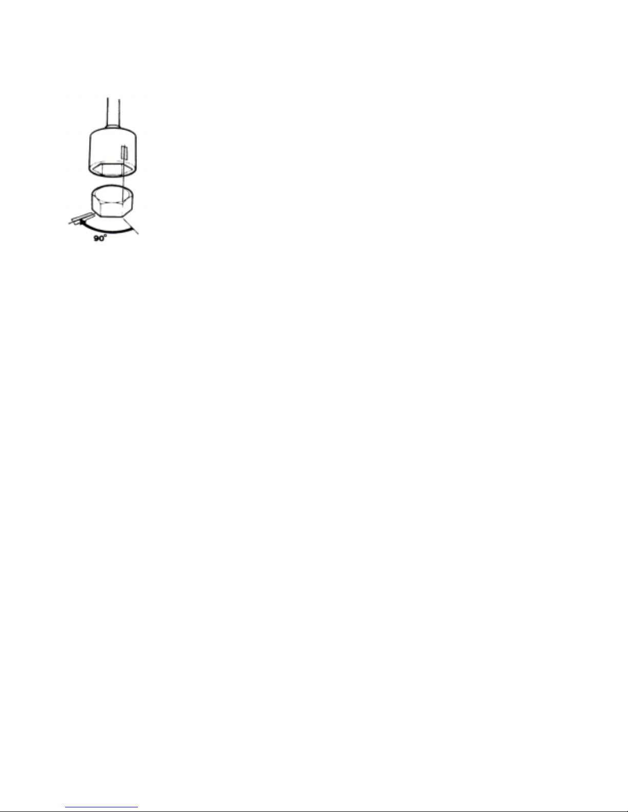
Tightening torques-protractor (angle)
tightening
Tightening using both a torque
setting and a protractor angle
requires that first the
recommended torque is applied
using a torque wrench and then
the recommended angle is
added according to the
protractor scale. Example: a
9Q0 protractor tightening
means that the joint is
tightened a further 1/4 turn in
one operation after the stated
tightening torque has been
applied.
Locknuts
Do not re-use lock nuts that have been removed during dismantling as they have reduced service life
when re-used - use new nuts when assembling or reinstalling. For lock nuts with a plastic insert such as
Nylock® the tightening torque stated in the table is
reduced if the Nylock® nut has the same head height
as a standard hexagonal nut without plastic insert.
Reduce the tightening torque by 25% for bolt size 8
mm or larger. Where Nylock® nuts are higher, or of
the same height as a standard hexagonal nut, the
tightening torques given in the table apply.
Tolerance classes
Screws and nuts are divided into different strength
classes, the class is indicated by the number on the
bolt head. A high number indicates stronger material,
for example a bolt marked 10-9 indicates a higher
tolerance than one marked 8-8. It is therefore
important that bolts removed during the disassembly
of a bolted joint must be reinstalled in their original
position when assembling the joint, It a bolt must be
replaced check in the replacement parts catalogue to
make sure the correct bolt is used.
Sealants
A number of sealants and locking liquids are used on
the engines. The agents have varying properties and
are used for different types of jointing strengths, oper
ating temperature ranges, resistance to oil and other
chemicals and for the different materials and gap sizes in the engines.
To ensure service work is correctly carried out it is
important that the correct sealant and locking fluid
type is used on the joint where the agents are required.
In this Volvo Penta Service Manual the us er will find
that each section where these agents are appli ed in
production states which type was used on the
engine.
During service operations use the same agent or an
alternative from a different manufacturer.
Make sure that mating surfaces are dry and free from
oil, grease, paint and anti-corrosion agent before applying sealant or locking fluid.
Always follow the manufacturer’s instructions for use
regarding; temperature range, curing time and any
other instructions for the product.
Two different basic types of agent are used on the
engine and these are:
RTV agent (Room temperature vulcanizing). Use for
gaskets, sealing gasket joints or coating gaskets.
RTV agent is clearly visible when a component has
been dismantled; old RTV must be removed before
the joint is resealed.
The following RTV agents are mentioned in the Service Manual: Loctite® 574, Volvo Penta 8408 79- 1,
Permatex®
No. 3, Volvo Penta P/N 1161099-5, Permatex® No.
77. Old sealant can be removed using methylated
spirits in all cases.
Anaerobic agents. These agents cure in an absence
of air. They are used when two solid parts, for example cast components, are installed face-to-face without a gasket. They are also commonly used to secure plugs, threads in stud bolts, cocks, o il pressure
switches and so on. The cured material is glass-like
and it is therefore colored to make it visible. Cured
anaerobic agents are extremely resistant to solvents
and the old agent cannot be removed. When
reinstalling the part is carefully degreased and then
new sealant is applied.
The following anaerobic agents are mentioned in the
Service Manual: Loctite® 572 (white), Loctite® 241
(blue).
NOTE! Loctite® is the registered trademark of Loctite Corporation,
Permatex® is the registered trademark of the Permatex
Corporation.
7
Page 9
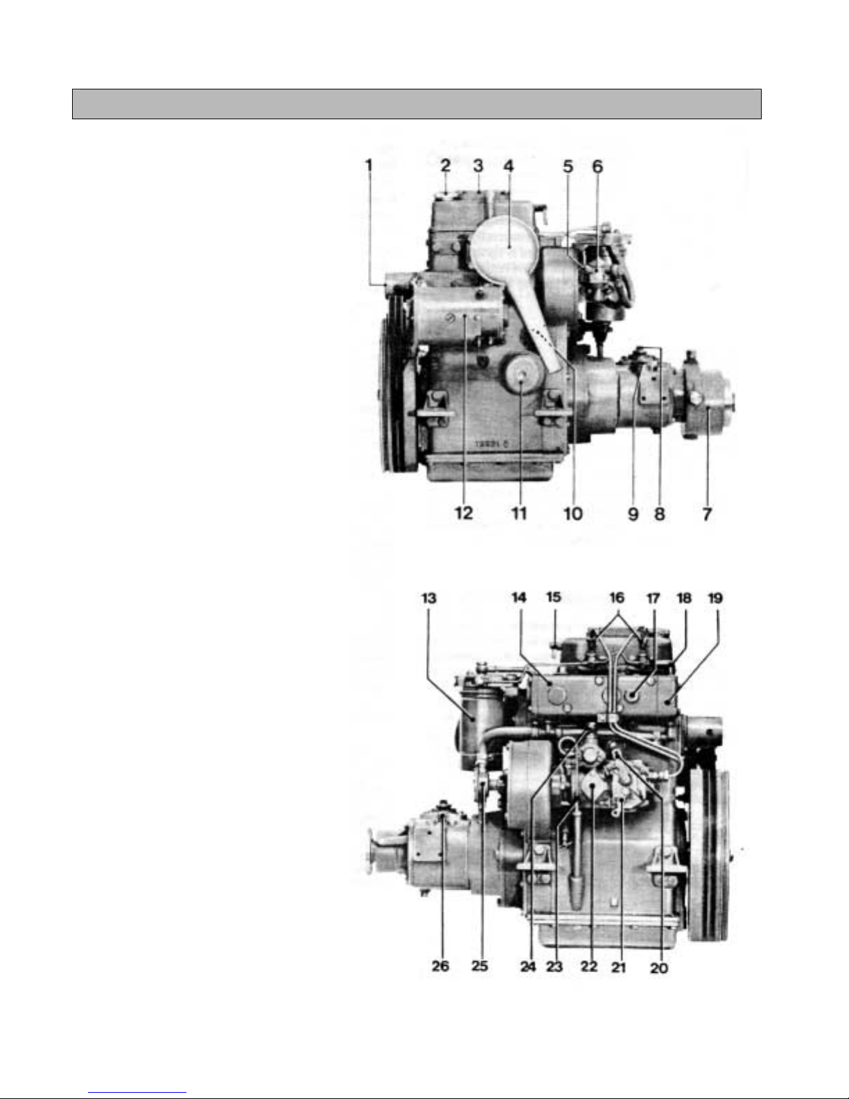
Presentation
MD6A
1. Recess for starting crank
2. Oil filling, engine
3. Sealed crankcase ventilation
4. Intake silencer
5. Connection, fuel inlet
6. Feed pump
7. Reduction reverse gear MS, red.
1.91:1
8. Control lever, reverse gear
9. Oil filling, reverse gear
10. Oil pressure contact
11. Lubricating oil filter
12. Start-generator
13. Fuel filter
14. Water-cooled exhaust manifold
15. Decompression handle
16. Injectors
17. Temperature sender
18. Cooling water outlet
19. Thermostat housing
20. Throttle lever
21. Stop lever
22. Fuel injection pump
23. Oil dipstick, engine
24. Fuel return line connection
25. Sea-water pump
26. Oil dipstick, reverse gear
8
Page 10
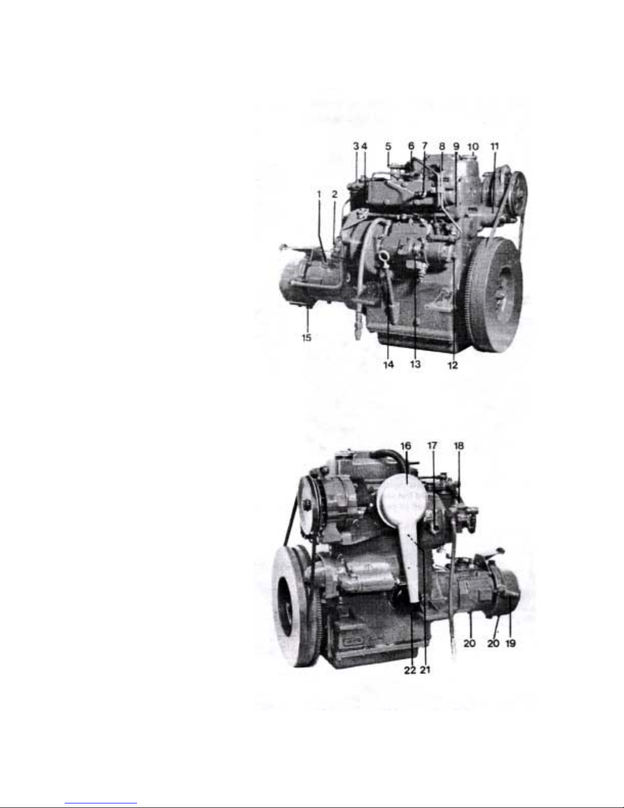
MD7A
1. Oil dip-stick and oil filling, reverse gear
2. Cover, cooling water pump
3. Bleed-screw, fine filter
4. Fine filter
5. Decompression handle
6. Pressure pipe nut
7. Temperature sender
8. Injector
9. Thermostat housing
10. Oil filling, engine
11. Hand start
12. Cooling water drain, engine
13. Fuel injection pump
14. Oil dip-stick, engine
15. Cooling water drain, reverse gear
16. Air cleaner and intake silencer
17. Sender, rev, counter
18. Fuel pump (with hand pump)
19. Cooling water inlet, reduction gear
20. Oil drain, reverse gear, reduction gear
21. Warner, low oil pressure
22. Oil filter
9
Page 11
Repair instructions
Drain the cooling water and oil from the engine. Then
clean the outside of the engine. Remove the rever s e
gear, 4 bolts.
Removal
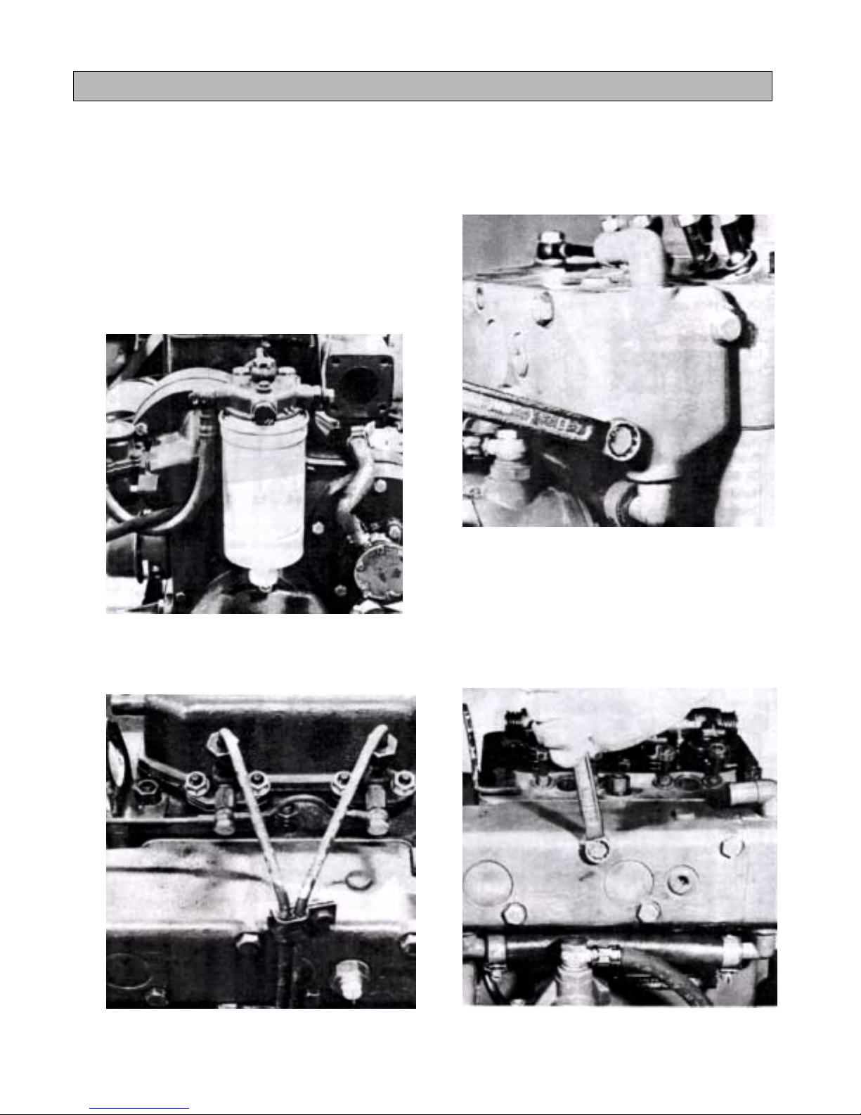
1. Remove the air cleaner, disconnect the
alternator electric cables and the oil pressure
cable, remove the alternator and the drive belts.
Then remove the sea-water pump, the oil filter,
the fuel filter and the feed pump. (Look out for
fuel and oil splash.)
3. Remove the thermostat housing (2 bolts) and the
hose clamp under the housing. Take the
thermostat out of the exhaust manifold. Note the
small O-ring which seals against the exhaust
manifold.
2. Remove the injectors and pipes as well as the
leak-off oil pipe. Discard the sealing washers on
both sides of the leak-off oil pipe.
4. Remove the exhaust manifold (4 bolts).
10
Page 12
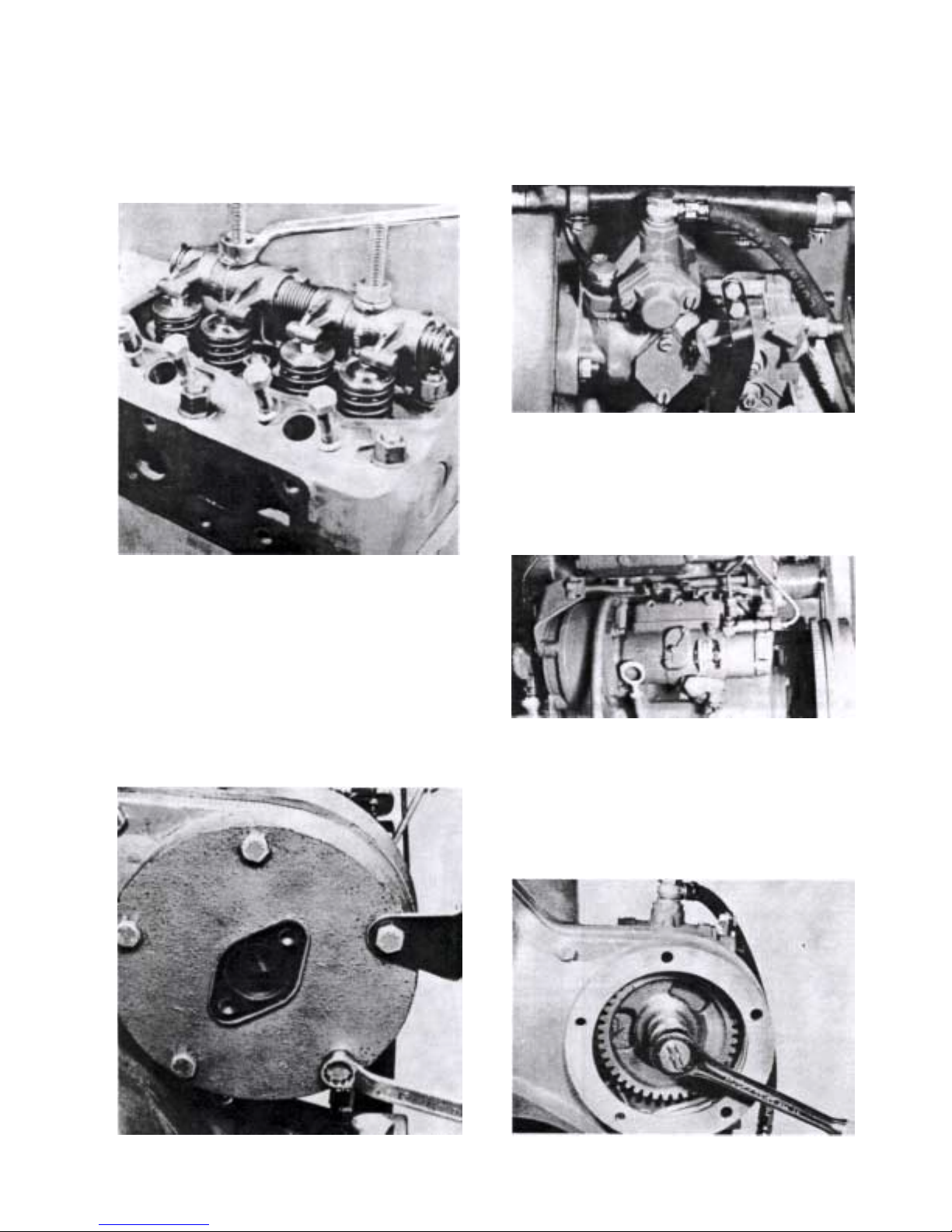
5. Remove the rocker arm cover (2 nuts), the intake
manifold (4 bolts), the rocker arm (2 nuts) and
the cylinder head (9 bolts). Take care of the
washers.
6. Remove the cover on which the water pump is
mounted. NOTE! Two of the five bolts are
shorter than the other three and are placed
towards the centre of the engine. Take care of
the control bracket. Discard the old gasket.
7. a. (BOSCH pump) Disconnect the pipe from the
fuel filter and remove the nuts for the fuel
injection pump.
7. b. (CAV pump) Disconnect the pipe from the fuel
filter and remove the nuts for the fuel injection
pump.
8. Remove the nut which drives the water pump.
Use the flywheel as a counterhold. Remove the
fuel injection pump and the gear wheel.
11
Page 13
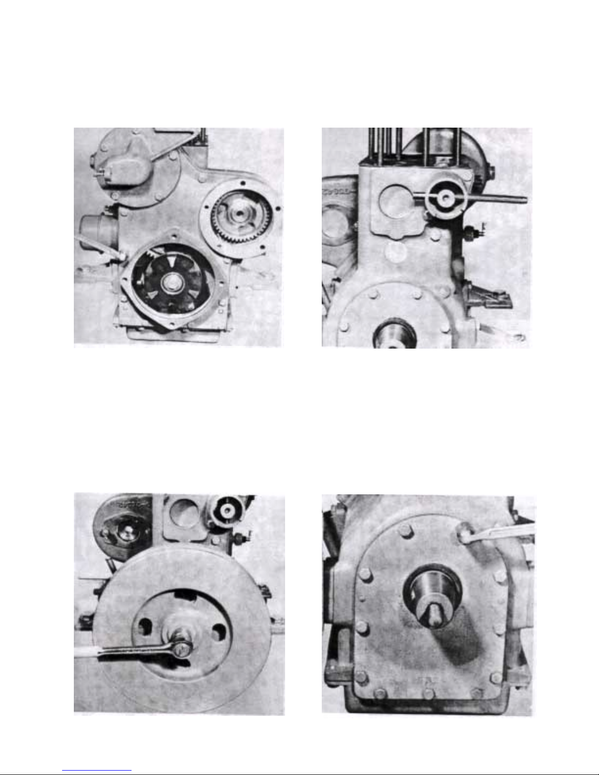
9. Remove the timing gear cover. NOTE! The small
round cover on which the fuel pump is mounted
has bolts with 3 different lengths. The bolts for
the large casing has two lengths. The two bottom
bolts are shorter than the others. Carefully lever
loose the timing gear casing from its guide pins.
Discard the gasket.
11. Knock out the hand starter pin in the camshaft.
Remove the protective cover (2 bolts). NOTE!
Scrap the sealing ring and fit a new one.
10. Remove the flywheel. Remove the nut and use a
puller. The axle is tapered and provided with a
key. Use a counterhold when releasing the nut.
12. Remove the front cover behind the flywheel (11
bolts). Note the guide pins. Carefully tap all
round. Replace the gasket and the sealing ring.
12
Page 14
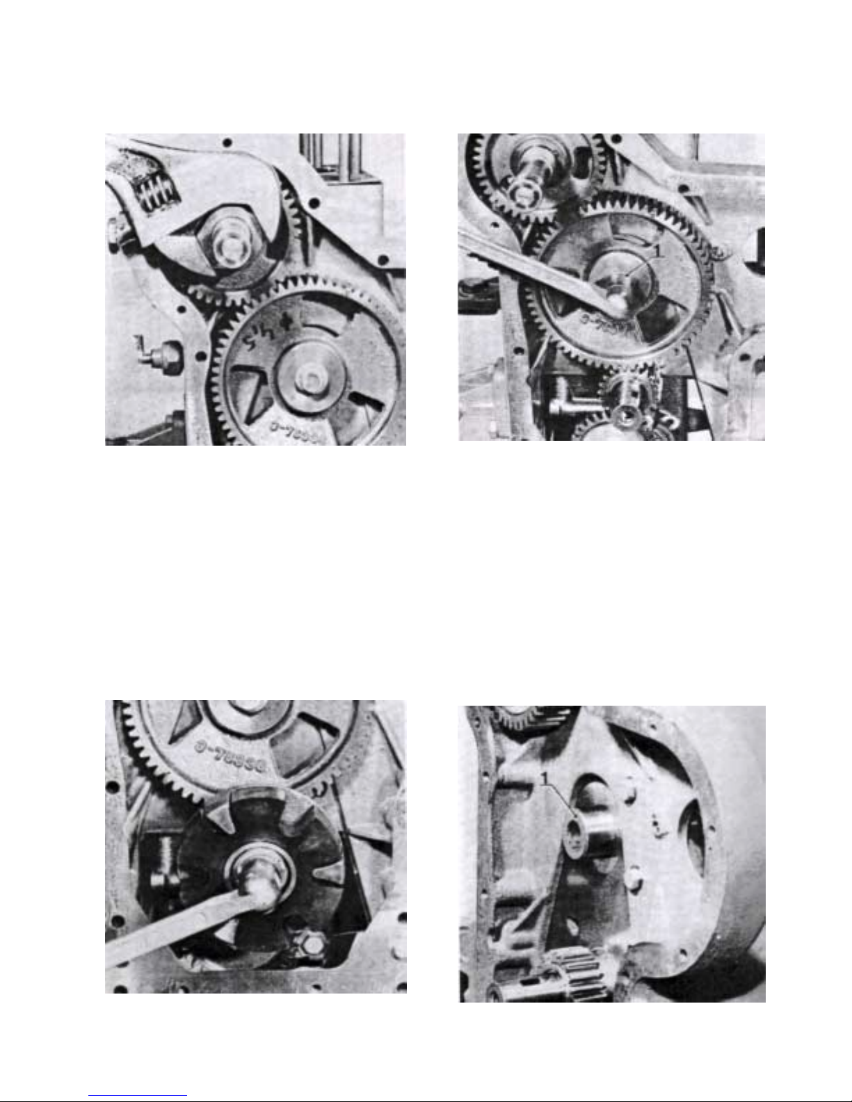
13. Remove the sump as well as the nut and lock
washer for the camshaft. Use a counterhold on
the crankshaft.
15. Remove the bolt for the intermediate gear. Discard the sealing washer 1 under the bolt. Pull off
the intermediate gear.
14. Bend down the lock washer and release the bolt
securing the reverse gear flange to the
crankshaft. Use a counterhold. NOTE! Take care
of the key. Lever loose the rubber damper with a
screwdriver.
16. Check that the shaft pin 1 for the intermediate
gear is secure.
13
Page 15

17. Remove the gearwheel for the camshaft by tapping the camshaft on the flywheel side with a
plastic mallet or similar tool. Lift out the shaft and
take care of the cover.
19. Invert the engine and remove the oil strainer (2
bolts and 1 nut).
18. Remove the 4 bolts holding the timing gear casing. The casing also sits on guides. Carefully lever all round and remove the casing.
20. Unscrew the bolts and remove the caps. Then
carefully tap out the pistons and connecting rods.
Place connection rods and caps in the same pairing as when removed to prevent them getting
mixed up if they are not marked. NOTE! Also
mark the piston and connecting rod for the respective cylinders (see point 21). On earlier engines there is no marking on the pistons and connecting rods. During overhauling, these engines
must be marked in the same way as those
produced later on.
14
Page 16

21. Mark the connecting rod and cap nearest the flywheel with a peener. Peen as shown in Fig. 21.
23. Remove the centre nut and washer for the gear
wheel on the lubricating oil pump. The shaft is tapered and the gear wheel sits on a key.
22. Remove the main bearing caps and lubricating
oil pump.
The main bearing caps are marked with a 2 or 3.
The corresponding figures are punched into the
block. Replace the axial bearings 1. Check that
the guide 2 for the caps is in good condition. Lift
out the crankshaft.
24. Remove the bolts (4) from the pump body cover
and lift off the cover. Clean the body and check
that the gears are in good condition. Replace damaged parts.
15
Page 17

25. Re-fit the gears as shown in the Fig. below. Fit
the cover together with a new gasket. Tighten up
the 4 bolts and rotate the shaft to make sure that
it does not jam. Fit the key in its groove and re-fit
the gear wheel. Fit the spring washer and tighten
up the gear with the nut.
27. Check for wear on pistons, piston rings and gudgeon pins. Replace if necessary. The piston and
connecting rod must be matchfitted as shown in
fig. A. Make absolutely certain that the groove
ring for the gudgeon pin is fitted in its groove.
The piston rings are fitted with a piston ring rod.
Begin with the oil ring 1 (fig B) in the lowest
groove. Continue with the compression ring 2.
Finally fit the compression ring 3. NOTE! The
marking TOP must face upwards. The other two
rings can be faced as desired.
26. Remove the bolt 1 for the relief valve and check
that the spring 2 and piston are in good
condition. If there is anything suspicious about
the opening pressure of the relief valve, check
the data for the spring. See under “Technical
Data, Lubricating oil pump”.
Clean and re-fit the piston and spring and tighten
up the bolt.
Crankshaft
28. Check the drive gear on the crankshaft for wear
or damage. Remove the drive gear with a puller.
Remove the key and clean the shaft. Check for
wear and grind the shaft if necessary. (See
under “Technical Data”.) Clean the engine block
and all other parts which must be re-fitted.
16
Page 18

Cylinder head
29. Remove the valve tappets. NOTE! Carefully
machine clean the valve tappets where they
have been smoothed down (1) in order to serve
as a counterhold for
force out the valve tappets as this could damage
the block etc.
30. Remove the seals on the valve stems. Remove
the valve springs with the help of a valve spring
remover. Remove all the collets 1. Remove the
valves. IMPORTANT! Place the valves in the order in which they are removed. Discard burnt
valves if the wear is excessive and grind valve
seats if necessary (See under Technical Data).
Seats and valves must be ground together so
that the contact surfaces will be absolutely tight.
the torque wrench. Do not
31. Replacing the valve guides.
With excessive clearance between the valve
stem and valve guide, the valve guide must be
replaced. (See under “Technical Data”.) Press
out the valve guides with tool 884538.
32. Fit new valve guides with tool 884549. Use a
press.
17
Page 19

Removing the nozzle sleeves
33. Insert the expander screw on tool 884541 into
the copper sleeve and screw anti-clockwise until
the screw has expanded and fastened in the
sleeve. Then pull hard so that the threads go into
the copper material. Fit the yoke on the stud
bolts holding the injector. Screw on the nut and
rotate until the sleeve is removed.
34. Replacing the 0-ring which seals between sleeve
and cylinder head.
Dip the 0-ring in soapy water before fitting it.
Wash and blow clean before filling the new
injector sleeve with tool 884539. knock in the
sleeve until it bottoms. Check to make sure that
the 0-ring is not damaged or has moved.
34. a. Oil the spreader tool
884537 and push the
tool into the sleeve (ensure that the bolt is
screwed back sufficiently). Place nuts or
washers on the stud
bolts so that the yoke
can be securely attached with nuts. Screw the
tool down as far as the
recess in the injector
sleeve allows. Thus
pressing out the sleeve.
Remove the tool.
Installing the valves
35. Thoroughly clean the cylinder head, valve guides
and valve seats. Use a small brush. Check that
the bevel on the seats is correctly ground by
applying marking blue to the bevel on the valve
disc and rotating it against the seat under light
pressure. If the blue is not distributed evenly on
the entire bevel surface of the seat (this indicates
a leaky valve), grind the valve further and recheck until results are successful. The width of
the seat should be approx. 1 mm (0.04”).
Oil the valve stems before filling them in their respective guides. IMPORTANT! Make sure that
the valves and valve springs are re-filled in their
original positions. Place the cylinder head on its
edge and fit the valve springs and collets 2. Use
a valve spring tool. Finally fit the rubber seal 1
(MD6A) on the intake valves.
Checking the cylinder head level finish
36. If there is any doubt as to the level finish of the
cylinder head after carrying out repairs, check as
follows:
Completely disassemble the cylinder head and
clean it thoroughly. Measure with the help of a
steel ruler (check the ruler against a flat disc) by
placing it on the cylinder head face as shown by
the arrows in the diagram below. Then measure
with a feeler gauge the gap between the ruler
and the face of the cylinder head at the marked
measuring points. A maximum gap of 0.00—0.10
mm (0.00—0.004”) measured crisscross (see
diagram below) and 0.00—0.10 mm (0.00—
0.004”) measured laterally (see diagram below)
is approved. If the measured gap is between
0.10 mm (0.004”) and 0.20 mm (0.008”), then the
gap must be grinded. If the gap exceeds 0.20
mm (0.008”), replace the cylinder head with a
new one.
18
Page 20

Pressure-testing the injectors
37. Check the spray pattern at an opening pressure
of 180 kp/cm
fuel jets cease simultaneously at all four holes
and there is no dripping afterwards.
Adjusting the opening pressure
38. Adjust the opening pressure with adjuster
washers 1, which are available in different
thicknesses ranging from 1 mm (0.04”) to 1.95
mm (0.08”) at intervals of 0.05 mm (0.002”)
between each washer.
Screw apart the injector and replace the adjuster
washer with a thinner or thicker one depending
on whether the pressure has to be reduced or increased. Screw the injector together again and
check the opening pressure and spray pattern.
Continue this procedure until results are satisfactory.
2
(2560 Ibf/in2). Also check that the
Overhauling the feed pump
39. Exert force on the pump lever (see Fig.). If the
pump “squeaks” then it is in good condition. If it
does not, the diaphragm must be replaced. This
is done as follows:
40. Release the cover centre screw, lift out the strainer 1 and clean it.
19
Page 21

41. Unscrew the six bolts holding the upper and
lower sections of the pump body together.
Remove the pump lever spring 1, and unscrew
the screw 2, which holds the pump lever shaft.
42. Press down the diaphragm and shake forwards
the pump lever shaft 1 until the pump lever loosens. Then pull the diaphragm out of the body.
43. Undo the screw 1, and pull out the manual pump
lever 2 and replace the spring 3 if in poor condition. NOTE! keep an eye on the rubber seal
which is pressed into the body.
44. Thoroughly clean the pump body and replace
worn parts.
Re-fit the manual pump lever. Press the diaphragm in and fit the pump lever onto the diaphragm shaft. Then insert the shaft and tighten
it with the screw. IMPORTANT! Do not forget the
washer on the screw.
Place the strainer on the upper body section and
screw tight the cover and gasket. Assemble the
pump body halves and fit the retaining washer 1
for the spring 2 on the mechanical pump lever 3.
IMPORTANT! The retaining washer can only be
filled in one way. Fit the spring and then the 0ring 4 which seals against the engine.
20
Page 22

Overhauling the sea-water pump
45. Remove the cover (6 bolts). Replace the impeller
with the help of two screwdrivers or similar tools.
IMPORTANT! Protect the edges on the pump
body. See Fig. below. Lever out the impeller with
the screwdrivers so far that the bolt becomes visible.
46. Unscrew the bolt and pull the impeller off the
shaft. If the sealing rings also have to be replaced, the shaft can be pulled out entirely together
with the impeller, after which the bolt can be released.
47. Remove the sealing rings 2 and the 0-ring 1
(earlier engines), and clean the pump body and
shaft. (IMPORTANT! The pump must be
removed from the engine.) Check to make sure
there is no burr on the shaft. NOTE! A new 0-ring
must not be fitted.
48. Fit new sealing rings. IMPORTANT! Turn the
sealing rings so that they are in their proper
position and make sure that they do not block
the drain hole in the pump body Grease the shaft
and carefully fit it into the body. Screw it through
the sealing rings but make sure the rings are not
damaged when doing so. Place the shaft so far
into the housing that the bolt hole is outside: Fit
the impeller and screw in the bolt. Then carefully
push in the impeller until it bottoms. Place a new
gasket on the cover and tighten up with the 6
bolts.
21
Page 23

Checking the thermostat
49. Lower the thermostat into hot water and with a
thermometer test to see whether the thermostat
opens and closes at the right temperature. It
should start opening at 60
open at 74CC (165
0
it must be replaced. Clean and fit a new rubber
gasket 1 on the thermostat. Place a new 0-ring 2
for the water hole on the lower edge of the
thermostat housing and fit the housing on the
exhaust manifold.
INSTALLING THE ENGINE
50. Before installing, heat the crankshaft drive gear.
Place the key in the key slot on the crankshaft
and press on the new drive gear.
Fit new bearing shells. Oil the bearings. Install
the crankshaft. Fit an axial bearing half 1 on
each side of the intermediate main bearing with
the oil grooves 2 facing outwards.
0
C (1400F) and be fully
F). If the thermostat is faulty,
51. Oil and fit the bearing halves in the caps. Place
the caps according to the marking on the block.
Fit the remaining axial bearing halves on the
intermediate cap with the oil grooves facing
outwards. NOTE! Fit a new 0-ring on the rear
cap which is integrall y built with the lubr ic at ing oi l
pump. The tightening torque for the main
bearings is 50 Nm (5 kpm = 36 Ibftf). Turn the
engine.
52. Turn the piston rings so that their respective
gaps are apart from each other. The piston top is
marked with “Front” and should point towards the
flywheel. NOTE! Fit the connecting rod which is
marked with punch pops nearest the flywheel.
Carefully tap the piston downwards through the
installation tool with a wooden handle or similar.
Place the engine on its side and tighten up the
caps. Tightening torque = 50 Nm (5 kpm = 36
Ibftf). Lock the bolts with the lock washers.
22
Page 24

53. Fit the “protective cover” for the starting crank.
Replace the sealing ring and gasket.
54. Fit the camshaft. Observe due care so that the
sealing ring in the protective cover for the
starting crank is not damaged. Knock the
starting crank pin into the camshaft. Use a tube
or similar as a counterhold.
55. Fit a new gasket and install the timing gear
casing (4 bolts). Tap carefully so as not to
deform the guide pins.
56. Fit the key in the camshaft and then the gear
wheel. Turn the gear wheel so that the figure
which is punched on the ring gear faces
outwards. Fit the star washer and the nut on the
camshaft. Tighten up later on (see Point 59) .
When a new engine block is used, a new shaft
pin 1 for the intermediate gear must be fitted.
23
Page 25

57. Fit the intermediate gear. Check that the
punched-in figures on the crankshaft drive and
camshaft gear wheel coincide with the marking
on the intermediate gear.
58. Place the large flat washer on the intermediate
gear with the bevel facing outwards , and
thereafter the steel-rubber washer 1. Tighten
with the bolt. NOTE! On earlier engines a plastic
washer is used. This must be scrapped and
replaced by the steel-rubber one.
59. Install the fuel injection pump. Use a new
gasket. Fit the key on the pump shaft and install
the gear wheel. IMPORTANT! The figure must
face towards the figure on the intermediate gear.
Tighten up the gear wheel with the nut which
also functions as a flange for the water pump.
Tightening torque = 60 Nm (6 kpm = 43 Ibftf).
Use a counterhold.
Tighten the camshaft nut. Remove the counterhold.
60. Fit the cylinder head gasket. It can only be fitted
in one way. If the stud bolts in the cylinder head
must be replaced, fit the new ones to a torque of
20 Nm (2 kpm = 14 Ibffi). Fit the cylinder head.
All the nuts must have washers under them
except the one on which the lift eyelet is filled.
Tightening torque = 70 Nm (7 kpm = 50 Ibm).
NOTE! Tightening is in three stages.
First stage: 10 Nm (1 kpm = 7 Ibm)
Second stage: 40 Nm (4 kpm = 29 Ibffi)
Third stage: 70 Nm (7 kpm = 50 Ibm).
See tightening scheme below.
24
Page 26

61. Place a new gasket on the inner timing gear
cover and fit the outer timing gear casing. Two
short bolts are fitted at the bottom. Trim off any
part of the gasket which sticks out.
62. Fit a new gasket and cover where the water
pump is to be installed. NOTE! The control
bracket is fitted with one of the bolts. Two bolts
are shorter.
63. Place a new gasket on the water pump and fit it
with the two bolts. Make sure that the groove in
the pump shaft engages in the flange nut.
64. Fit the cover with new gasket over the camshaft
end. NOTE! The bolts have three different
lengths. The Fig. below shows where they are
placed.
25
Page 27

65. Install the fuel pump. Make sure that the 0-ring
is in position. Use a new 0-ring. The pump is
installed with two inhex bolts and spring
washers. Check that the pump “squeaks” by
pressing in the pump lever before installing the
pump on the engine. Connect up the fuel hoses.
66. Release the lock wire securing the lubricating oil
strainer. Lift out the strainer, wash it and blow it
dry with compressed air. Re-fit it and lock it with
the lock wire. Turn the engine and fit the
complete oil strainer.
67. Fit the oil sump together with a new gasket. The
gasket can only be fitted in one way. Begin with
the four corner bolts for locating the sump into
position. Tighten all the bolts thoroughly.
Remove the sealing ring on the casing for the
crankshaft (flywheel side). Fit a new sealing
ring. Trim off any part of the oil sump gasket that
is sticking out. Place a new gasket on the cover
and fit it. Carefully knock on the cover until it fits
over the guide pins. Tighten up the cover with
the bolts.
68. Fit the rocker arm, fuel filter and fuel lines.
NOTE! Replace the fine filter insert (see page
25, Point B) by turning the hex head in the
bottom of the container. When the installation of
the engine is completed, bleed the fuel system
through the bleeder screw 1. See more detailed
instructions about this on page 25, Po int B.
26
Page 28

69. Fit the key for the flywheel and push on the flywheel. Fit the thick washer and tighten up the
flywheel with the nut. Tightening torque = 180
Nm (18 kpm = 130 lbftf). Use a counterhold
through the flywheel.
70. Oil the oil filter rubber gasket. Fit the oil filter and
the oil pressure contact. Screw in the oil filter so
far that the rubber gasket just touches the
engine. Then screw tight a further half turn.
IMPORTANT! Screw by hand.
71. MD6A. Install the stars generator with its
bracket. Screw tight the tensioning bar to the
engine. Earlier engines have a washer placed
between the engine and bracket.
MD7A. Install the alternator with its bracket.
Screw tight the tensioning bar to the engine.
72. Install the exhaust manifold. Fit a new gasket.
Check to make sure that the rubber hose for the
cooling water is in good condition. Fit the cooling
water hose from the cooling water pump and
tighten up the hose clamp.
27
Page 29

73. Fit the injectors and the overflow pipe.
Tightening torque for injectors’ nuts 1 = 8 Nm
(0,8 kpm = 5,8 lbftf). NOTE! Do not forget the
new sealing washers 2 on both sides of the
overflow pipe.
74. Fit the fuel pipes between the injection pump
and the injectors. NOTE! Check to make sure
that the brake pipes are properly installed, see
Fig.
75. Adjusting the BOSCH injection pump
a. Turn over the engine until the valves in cylinder
No. 2 “rock’. Continue to turn over the engine in
the normal direction of rotation until marking 10
on flywheel coincides with the marking on the
block.
b. Remove the pump inspection cover and check
that the marking (1) coincides exactly with the
pointer (2). Adjustments are made by slackening
the pump securing nuts and turning the pump.
c. Tighten the nuts.
d. Check the setting by turning over the engine 1/4
turn in the opposite direction of rotation, then
back again to the “10,’ marking on the flywheel.
Check that the marking (1) and the pointer (2)
still coincide.
e. Fit the inspection cover with the rubber gasket.
75a. Adjusting the CAV fuel injection pump
a. Rotate the flywheel in a clockwise direction until
both the valves on No. 1 cylinder are closed
(compression stroke).
b. Assemble the pump so that the marking coinci-
des with that on the transmission housing see
fig.
c. Fit on the gear wheel. NOTE! The figure (1) is to
be turned towards the figure (1) of the
intermediate wheel.
d. Bleed the air from the pump with the bleed-
screws in the following order 1, 2, 3.
76. Adjust the valves as follows:
Rotate the flywheel until both valves on a
cylinder “rock”. Turn the flywheel one further
turn and adjust the valves for this cylinder.
Repeat the procedure for the other cylinder.
With a hot engine, the clearance should be 0.30
mm (0.012”) for both the intake and exhaust
valves.
28
Page 30

77. Oil the rocker arm and fit the rocker arm cover
together with new gaskets. Fit the intake
manifold and gasket and inst all the air cl ean er.
Fit the ventilation hose between the rocker arm
cover and air cleaner.
NOTE! Fit the intake manifold with the flange
displaced towards the reverse gear side in order
to provide space for the air cleaner.
78. Fit the V-belts and tension the alternator. The
belts are properly tensioned when they can be
depressed under normal thumb pressure about
3 - 4 mm (1/8”). Depress between the startgenerator and flywheel.
79. Fit the key in the crankshaft. Heat the flange and
fit it on the shaft. Tighten it up with the bolt and
the thick washer. Tightening torque: 80 Nm (8
kpm = 57 lbftf). Bend down the thin washer over
the bolt head. Fit the rubber damper.
80. Install the reverse gear and gasket and connect
up the cooling water hose between the reverse
gear and water pump. Then fit the exhaust
elbow.
81. Fill the engine and reverse gear with oil. Concerning the oil quantity and quality, see under
“Technical Data”.
29
Page 31

Electrical system
ELECTRICAL SYSTEM
IMPORTANT
82. The following applies to engines fitted with
alternators:
1. Never break the current between the
alternator and battery while the engine is
running. If a main switch is fitted, it must not
be switched off until the engine has stopped.
Otherwise no cable must be disconnected while
the engine is running, since this also can ruin
the charging regulator.
2. Check regularly the battery, battery cables and
cable terminals. The battery poles should be
well-cleaned and the cable terminals always
well-tightened and well-greased to ensure
continuous function. All cables in general must
be well-tightened, there must be no loose
connections. Note! On no account must the
battery’s positive and negative poles be mixed
up when the battery is fitted.
Fig. 82 Wiring diagram for the MD6A with start-generator (no rev counter and temp. gauge)
3. When starting with the help of a helper battery,
first check that the helper battery has the same
rated current as the standard one. Connect the
helper battery to the standard battery, positive to
positive and negative to negative. Remove the
helper battery when the engine has started.
Note! The cables to the standard battery must
not be broken.
4. With electrical welding on the engine or installation components, the charging regulator cables
must first be disconnected and insulated. Both
the battery cables must also be disconnected.
5. In the event of repairs to the alternator
equipment, both battery cables must first be
disconnected. The same applies if the battery
has to be rapidly charged.
6. Never test any of the components with a
screwdriver, etc. against a terminal to see if it
sparks.
Cable Marking 1. Starter button
2
Des. Colour mm
A” Beige 2.5 13 3. Charging warning light
B Bl Black 1.5 15 4. Control light for oil pressure
C Red 25 3 5. Switch
C Red 2.5 13 6. Terminal board, instrument panel resp. engines
D Green 1.5 15 7. Charging regulator
D Green 2.5 13 8. Start-generator
G Brown 1.5 15 9. Oil pressure indicator
H Blue 1.5 15 10. Battery 12V, max. 60 Ah
H Blue 25 3 11. Main Switch
AWT 2. Key switch
30
Page 32

Fig. 83. Wiring diagram for late prod. Type MD6A
1. Key switch
2. Instrument panel switch
3. Temperature gauge
4. Warning light for “low oil pressure”
5. Rev counter
6. Warning light, charging start-generator
7. Switch, optional equipment
8. Terminal board
9. Warning light, charging alterna t or
(Optional Equipment)
10. Battery
11. Main switch
12. Start-generator
13. Alternator (Optional Equipment)
14. Charging regulator
15. Fuse
16. Temperature sender
17. Rev counter
18. Oil pressure sender
19. Other electrical equipment
31
Page 33

Wiring Diagram MD7A
CABLE MARKING
Des. Colour
A White 6 9
B Black 1.5 15
B’ Black 0.6 19
B” Black 0.75 18
C Red 6 9
C’ Red 35 1
C” Red 0.6 19
F Yellow 1.5 15
G Brown 1.5 15
H Blue 4 11
H’ Blue 35 1
I’ Green/red 0.75 18
J Green 1.5 15
J’ Green 0.6 18
J” Green 0.75 18
K Blue/yellow 0.75 18
L White/red 0.75 18
M Blue/red 0.75 18
2
AWG
mm
Position List
2. Charging warning light
3. Warning light for “high temperature”
4. Warning light for “low oil pressure”
5. Key switch 12. Alternator
6. Siren 13. Fuse
7. Alarm unit 14. Main switch
9. Place for instrument, extra equipment 15. Battery
10. Terminal board 16. Temperature sender
11. Starter motor 17. Oil pressure sender
32
Page 34

FAULT TRACING
The fault-tracing scheme below includes only those
faults which arise most often during operation.
Fault-tracing scheme
FAULT Notes
Engine does not start
Engine stops
X
X X
X X X
X X X X Defective injectors C
X
X X Damaged propeller E
X
A.
Check the state of charge of the battery with the help
of a hydrometer which shows the specific gravity of the
battery acid. This will vary with the state of charge, see
under “Technical Data”. Also see under “Electrical
system” on page 23.
B. Replace the fine filter by turning the hex head in the
bottom of the container. The fine filter and container
are of the throw-away type. They must be discarded
and a new one installed. Check that the contact
surface for the cover is absolutely clean and that the
filter gasket is in good condition. Screw on the new
filter tight by hand until the gasket goes against the
cover. Then tighten the filter a further 1/2 turn. The
bottom of the filter container has a drain plug for
draining water and impurities that have accumulated in
the fuel. Bleed the fuel system after draining and
replacing the filter, also check for leakage.
Remove the feed pump cover and clean the pre-filter
in the fuel oil. Then fit the filter with the pins facing
upwards and place the gasket (undamaged) in position
and tighten up the cover. Bleed the fuel system.
Check and if necessary drain the extra fuel filter if such
is fitted. Look out for fuel splash.
ull throttle
Engine does not reach
right operating speed at
Engine runs unevenly or
vibrates abnormally
Engine becomes
abnormally hot
Main switch not on,
flat battery, broken
electric cables
Empty fuel tank,
closed fuel cock,
blocked fuel filter
Water, air or
impurities in fuel
Boat abnormally
loaded. Growth on
boat bottom.
Clogging of cooling
water intake,
cooling jackets,
defective impeller
or thermostat
A
B
B
D
F
Bleeding the fuel system
To ensure that the engine starts, the fuel system must
be bled on the following occasions: 1) When changing
the fine filter. 2) When draining through the drain plug.
3) When cleaning the pre-filter. 4) When running the
fuel tank empty. 5) When installing the fuel injection
pump. 6) With leakage and when working on the fuel
line. 7) When the engine has been stopped for a long
time. Bleeding is as follows: Open the bleeder screw 1
on the fine filter. See Point 68. Pump forward the fuel
with the help of a hand primer until about 0.2 litre (0.2
qt.) fuel has run out. Close the bleeder screw. If you
get poor pumping effect, turn over the engine a bit so
that the pump drive cam alters its position. If the fuel
injection pump has been removed, or when starting an
entirely new engine for the first time, the fuel injection
pump must be bled. Pump with the hand primer for
about 1/2 minute. This automatically bleeds the fuel
injection pump. Slacken the delivery pipe nuts for the
injectors and turn over the engine with the startgenerator until fuel comes from the delivery pipes.
Tighten up the delivery pipe nuts and start the engine.
C. Check the injectors with regard to their opening
pressure, tightness and spray pattern. Max. running
time of 400 operating hours or once a season is
recommended between these checks. See also Points
37 and 38.
D. In order to get the best possible operating economy,
the engine speed selected should be minimum 300
rev/mm below the max. speed for The engine during
lengthy periods of operation. When the boat has been
in the water for so’ time, the max. speed for the engine
can drop due to growth on the outside of the hull. Use
anti-fouling paint. Check and clean the hull regu larly .
E. Check the propeller blades. If a propeller blade is
damaged, the propeller must be replaced. A propeller
blade can also be warped, something which is very
difficult to discover. Place the propeller on a flat disc
and measure the blades. If a propeller blade is
warped, the propeller should be replaced.
F. Check the cooling system for leakage, clogging, etc.
Check to make sure the thermostat opens at the right
temperature. The thermostat can be removed after
having taken down the thermostat housing at the front
of the exhaust manifold. See also Point 49. The pump
body in the sea-water pump is made of neoprene
rubber, which can be damaged with shortage of water,
e.g., in the event the sea-water inlet is blocked.
Proceed according to Points 45-48 in the event the
impeller and sealing rings have to be replaced. NOTE!
If the boat is in the water, the bottom cock must be
closed before the sea-water pump is removed. But do
not forget to open the cock again.
33
Page 35

Special Tools
Part No. Description
884537
884538
884549
884539
884541
884535
884543
34
Page 36

Technical Data
Technical Data MD6A
General
Type designation
Output (DIN) at 40 rev/sec (2400 rev/mm)
Number of cylinders
Bore
Stroke
Capacity
Compression ratio
Compression pressure at starter motor speed
Direction of rotation, viewed towards flywheel
Idling speed
Oil pressure, hot engine
Oil pressure, idling, hot engine
Cylinders
Material
Bore, standard
0.500 mm (0.020”) oversize
Pistons
Material
Height, total
Height from gudgeon pin centre to piston crown
Piston clearance in cylinder
Pistons, standard
0.500 mm (0.020”) oversize
Gudgeon pins
Diameter
Gudgeon pin bushing, diameter
Clearance, gudgeon pin — bushing
Piston rings
Compression rings, number
Oil scraper ring, number
Upper compression ring has chromium lining
Piston rings are available for standard size and 0.500 mm
(0.020”) oversize
Piston ring clearance in groove, axially:
Upper compression ring
Lower compression ring
Oil scraper ring
Piston ring gap in cylinder:
Upper compression ring
Lower compression ring
Oil scraper ring
Crankshaft
Material
Crankshaft axial clearance
Main bearing radial clearance
Connecting rod radial clearance
1)
Measured with Moto Meter nipple 884535 and yoke 884543.
MD6A
7.4 kW (10 h.p.)
2
70 mm (2.7560”)
82 mm (3.2283”)
0.63 dm
18.7:1
23—25 kp/cm
3
2
(327—355 lbf/in2)1)
Clockwise
12 rev/sec (700 rev/min)
4 kp/cm
0,8 kp/cm
2
(57 lbf/in2)
2
(11 lbf/in2)
Cast iron
70.000—70.019 mm (2.7560—2.7566”)
70.500—70.519 mm (2.7755—2.7763”)
Light-metal
81 mm (3.19”)
51 mm (2.00”)
0.086—0.130 mm (0.0034—0.0051”)
69.889—69.914 mm (2.7515—2.7525”)
70.389—70.414 mm (2.7712—2.7722)
27.9975—28.0025 mm (1.1023—1.1025”)
28.0125—28.0225 mm (1.1029—1.1032”)
0.010—0.025 mm (0.0004—0.0010”)
2
1
0.062—0.113 mm (0.0024—0.0044”)
0.037—0.087 mm (0.0015—0.0034”)
0.037—0.089 mm (0.0015—0.0035”)
0.279—0.406 mm (0.0110—0.0160”)
0.203—0.330 mm (0.0080—0.0130”)
0.350—0.480 mm (0.0140—0.0189”)
Nodular iron
0.08—0.31 mm (0.0031—0.0122”)
0.026—0.075 mm (0.0010—0.0030”)
0.026—0.075 mm (0.0010—0.0030”)
35
Page 37

Main bearing journals
Diameter, standard
0.300 mm undersize
0.600 mm undersize
Main bearing shells
Thickness, standard
0.300 mm oversize
0.600 mm oversize
Connecting rod journals
Diameter, standard
0.300 mm undersize
0.600 mm undersize
Connecting rod shells
Thickness, standard
0.300 mm oversize
0.600 mm oversize
Connecting rods
End play at crankshaft
Camshaft
End play
Radial clearance in bearing
Camshaft diameter
Lift height of cams
Bushing, diameter
Cylinder head
Material
Intake valves
Disc diameter
Stem diameter
Valve seat angle
Cylinder head seat angle
Width of seat in cylinder head
Clearance, hot engine
Exhaust valves
Disc diameter
Stem diameter
Valve seat angle
Cylinder head seat angle
Width of seat in cylinder head
Clearance, hot engine
Valve guides
Length, intake valve
Length, exhaust valve
Bore
Height above cylinder head spring face
Clearance, valve stemguide
49.984—50.000 mm (1.9679—1.9685”)
49.684—49.700 mm (1.9560—1.9567”)
49.384—49.400 mm (1.9442—1.9449”)
1.730—1.737 mm (0.0681—0.0684”)
2.030—2.037 mm (0.0800—0.0802”)
2.330—2.337 mm (0.0917—0.0920”)
49.984—50.000 mm (1.9679—1.9685”)
49.684—49.700 mm (1.9560—1.9567”)
49.384—49.400 mm (1.9442—1.9449”)
1.730—1.737 mm (0.0681—0.0684”)
2.030—2.037 mm (0.0800—0.0802”)
2.330—2.337 mm (0.0917—0.0920”)
0.25—0.50 mm (0.0100—0.0200”)
0.160—0.300 mm (0.0063—0.0118”)
0.017—0.083 mm (0.0007—0.0033”)
43.992—44.008 mm (1.7320—1.7326”)
5.48—5.52 mm (0.2157—0.2173”)
44.025—44.075 mm (1.7333—1.7352”)
Special-alloy cast iron
28.8—29.0 mm (1.1338—1.1417”)
7.938—7.960 mm (0.3125—0.3134”)
29.25—29.50°
30°
approx. 1 mm (0.040”)
0.30 mm (0.012”)
26.3—26.5 mm (1.0354—1.0433”)
7.938—7.960 mm (0.3125—0.3133”)
29.25—29.50°
30°
approx. 1 mm (0.040”)
0.30 mm (0.012”)
43 mm (1.6930”)
49 mm (1 .9291”)
8.000—8.022 mm (0.3150—0.3158”)
10.7—11.0 mm (0.4212—0.4331”)
0.040—0.084 mm (0.0016—0.0033”)
36
Page 38

Valve springs
Length, off-load
Loaded with 150 N (15 kp = 33 Ibf.)
Loaded with 230 N (23 kp = 50 lbf.)
Lubricating system
Engine
Oil capacity excl. filter
Oil capacity incl. filter
Oil quality acc. to API-system
Viscosity, above +10
Viscosity, below +10
Oil pressure, hot engine, idling speed
Oil pressure, hot engine, full speed
Reverse gear
Oil quality/Viscosity
Oil capacity, din
Oil capacity, din
Combi reduction gear
Reduction gear
Reversing mechanism and propeller hub
Lubricating oil filter
Designation
Lubricating oil pump
Type
Relief valve spring: Length, off-load
Loaded with 15 N (1.5 kp = 3.3 lbf)
Loaded with 46 N (4.6 kp = 10 Ibf)
Axial clearance of gear wheels incl. gasket
Fuel system
Fuel injection pump, make Bosch
Injectors, make Bosch, holders
Nozzles
Hole diameter
Opening pressure
Spray angle
Advance angle
Injection quantity
Max. speed
Fine filter
Type
Filter insert
Feed pump
Type
Feed pressure at 40 rev/see (2400 rev/mm)
0
C (500F)
0
C (500F)
3
(qts.), red. 1:1
3
(qts.), red. 1.91 :1
47 mm (1 .8504”)
30 mm (1.1811”)
21 mm (0.8268”)
2.8 litres (2.5 Imp.qts. = 2.9 US qts.)
3.0 litres (2.6 lmp.qts. = 3.2 US qts.)
CD (DS)
SAE 30
SAE 20W
0.8—1 .5 kp/cm
3.5—4.0 kp/cm
2
(11 .4—2 1 .3 Ibf/in2)
2
(50—57 lbf/in2)
Same as for engine
0.4 (0.4)
0.55 (0.5)
same oil compartment as engine’s
Lubricating grease Shell Alvania EP2 or similar
AC-DELCO, 1530838 type SA
Gear wheel pump
45 mm (1.7717”)
40 mm (1.5748”)
29 mm (1.1417”)
0.048—0.084 mm (0.0020—0.0033”)
0 460 302 006
0 431 112 001
0 433 171 001
Four, 0.22 mm (0.0087”)
180 kp/cm
2
(2560 Ibf/in2)
150°
12°
20 mm
3
/stroke at 31.7 rev/sec
(1900 rev/min)
40.8—42.5 rev/sec (2450—2550 rev/min)
Bosch 0 450 133 001
Bosch 1 457 434 0611
Pierburg PE 15672
0.65—0.85 kp/cm
2
(9.2—12.0 lbf/in2)
37
Page 39

Electrical system
Battery voltage
Battery capacity
Start-generator
Generator output, max
Generator output, continuous
Starter motor output
Battery electrolyte specific gravity: Fully charged batter
When charging has to be carried out
Cooling system
Thermostat
Starts opening at
Fully open at
WEAR TOLERANCES
Cylinders
Drilled with wear (or if engine has abnormal fuel
consumption)
Crankshaft
Main bearing and connecting rod journals
Permitted out-of-roundness
Permitted taper
Max. axial play on crankshaft
Camshaft
Bearing journals, permitted out-of-roundness
Max. clearance between camshaft and bushings
Valves
Max. clearance between valve stem and guide
Edge of valve disc should be mm
TIGHTENING TORQUES
Cylinder head nuts
Cylinder head stud bolts
Bolt for flange on crankshaft
Flywheel nut
Connecting rod bolts
Water pump flange
Main bearings
Nuts for fork for injectors
Tightening scheme for cylinder head nuts
12 V
Max. 60 Ah
Bosch 0 010 350 004
135W
90 W
0.74 kW (1 h.p.)
1.275—1.285 g/cm
1.230 g/cm
3
3
Bellows thermostat
0
60
C (1400F)
0
74
C (1650F)
0.25 mm (0.010)
0.06 mm (0.0024”)
0.05 mm (0.0020”)
0.36 mm (0.0142”)
0.03 mm (0.0012”)
0.15 mm (0.0060”)
0.16 mm (0.0063’)
1.0 mm (0.0400”)
Nm Kpm Lbftf
70 7 51
20 2 14
70 7 50
180 18 130
50 5 36
60 6 43
50 5 36
8 0.8 5.8
38
Page 40

Technical Data MD7A
General
Type designation
Output at flywheel (DIN) at 43 rev/sec. (2600 rev/mm.)
Number of cylinders
Bore
Stroke
Capacity
Compression ratio
Compression pressure at starter motor speed
Direction of rotation, viewed towards flywheel
Idling speed
Oil pressure, full speed, hot engine
Oil pressure, idling, hot engine
Cylinders
Material
Bore, standard
0.25 mm (0.010”) oversize
0.50 mm (0.020”) oversize
Pistons
Material
Height, total
Height from gudgeon pin centre to piston crown
Piston clearance in cylinder
Pistons, standard diameter
0.25 mm (0.010”) oversize
0.50 mm (0.020”) oversize
Gudgeon pins
Diameter
Gudgeon pin bushing, diameter
Clearance, gudgeon pin - bushing
Piston rings
Compression rings, number
Oil scraper ring, number
The upper compression ring is chromium lined
Piston rings are available for standard size, 0.250 mm
(0.010’) and 0.500 mm (0.020”) oversize
Piston ring clearance in groove, axially:
Upper compression ring
Lower compression ring
Oil scraper ring
Piston ring gap in cylinder
Upper compression ring
Lower compression ring
Oil scraper ring
Crankshaft
Material
Crankshaft axial clearance
Main bearing radial clearance
Big-end bearings, radial clearance
MD7A
10 kW (13.4 h.p.)
2
76 mm (2.9921”)
82 mm (3.2283”)
0.744 dm
17:1
2-2.5 MPa (20—25 kp/cm
Clockwise
11—13 rev/sec (650—780 rev/min)
0.35-0.40 MPa (3.5-4.0 kp/cm
0.08-0.15 MPa (0.8-1.5 kp/cm
Cast iron
76.00—76.03 mm (2.9921—2.9933”)
76.25—76.28 mm (3.0020—3.0032”)
76.50—76.53 mm (3.0118—3.0130”)
Light-alloy
76.4 mm (3.0079”)
51.4 mm (2.0236”)
0.073—0.118 mm (0.0029—0.0046”)
75.912—75.927 mm (2.9883—2.9893”)
76.162—76.177 mm (2.9985—2.9991”)
76.412—76.427 mm (3.0084—3.0090”)
28.000—28.004 mm (1.1024—1.1025”)
28.0125—28.0225 mm (1.1029—1.1032”)
0.0085—0.0230 mm (0.0003—0.0009”)
2
1
0.070—0.102 mm (0.0028—0.0040”)
0.050—0.082 mm (0.0020—0.0030”)
0.030—0.062 mm (0.0012—0.0024”)
0.30—0.50 mm (0.0120-0.020”)
0.30—0.50 mm (0.0120-0.020”)
0.25—0.50 mm (0.010-0.020”)
Nodular iron
0.080—0.313 mm (0.0032—0.0123”)
0.026—0.075 mm (0.0010—0.0030”)
0.026—0.075 mm (0.0010—0.0030”)
3
2
) (284—355 lbf/in2)
2
) (50-57 lbf/in2)
2
) (11-21 lbf/in2)
39
Page 41

Main bearing journals
Diameter, standard
0.300 mm (0.0120”) undersize
0.600 mm (0.0236’) undersize
Main bearing shells
Thickness, standard
0.300 mm (0.0120”) oversize
0.600 mm (0.0236”) oversize
Big-end journals
Diameter, standard
0.300 mm (0.0120”) undersize
0.600 mm (0.0236”) undersize
Big-end bearing
Thickness, standard
0.300 mm (0.0120”) oversize
0.600 mm (0.0236”) oversize
Connecting rods
End play at crankshaft
Camshaft
End play
Radial clearance in bearing
Camshaft diameter
Lift height of cams
Bushing, diameter
Cylinder head
Material
Intake valves
Disc diameter
Stem diameter
Valve seat angle
Cylinder head seat angle
Width of seat in cylinder head
Clearance, hot engine
Exhaust valves
Disc diameter
Stem diameter
Valve seat angle
Cylinder head seat angle
Width of seat in cylinder head
Clearance, hot engine
Valve guides
Length, intake valve
Length, exhaust valve
Bore
Height above cylinder head spring face
Clearance, valve stem - guid e:
intake valve
exhaust valve
49.984—50.000 mm (1 .9679—1.9685”)
49.684—49.700 mm (1.9560—1.9567”)
49.384—49.400 mm (1.9442—1.9449”)
1.730—1.737 mm (0.0681—0.0684)
1.880—1 .887 mm (0.0740—0.0743”)
2.030—2.037 mm (0.0799—0.0802”)
49.984-50.000 mm (1.9679—1. 9685”)
49.684—49.700 mm (1.9560—1.9567”)
49.384—49.400 mm (1.9442—1.9449”)
1.730—1.737 mm (0.0681—0.0684”)
1.880—1.887 mm (0.0740—0.0743”)
2.030—2.037 mm (0.0799—0.0802”)
0.25—0.50 mm (0.0100—0.0200”)
0.160—0.300 mm (0.0063—0.0118”)
0.01 8—0.083 mm (0.007—0.0033”)
43.992—44.008 mm (1 .7320—1.7326”)
5.48—5.52 mm (0.2157—0.2173”)
44.026—44.075 mm (1 .7333—1.7352”)
Special-alloy cast iron
32.4—32.6 mm (1.2756—1.2835”)
7.955—7.970 mm (0.3132—0.3138”)
45° 15’ - 45° 45’
45°
approx 1 mm (0.040”)
0.30 mm (0.012”)
27.4-27.6 mm (1.0787—1.0866”)
7.950—7.965 mm (0.3130—0.3136)
45° 15’ - 45° 45’
45°
approx 1 mm (0.040”)
0.30 mm (0.012”)
38 mm (1 .4961”)
38 mm (1 .4961”)
8.0—8.015 mm (0.3150—0.3156”)
8.85—9.15 mm (0.3484—0.3602”)
0.03—0.06 mm (0.0012—0.0024”)
0.035—0.065 mm (0.0014—0.0026”)
40
Page 42

Valve springs
Length, off-load
Loaded with 170±10 N (17±1 kp = 37.5±2 lbf)
Loaded with 300±20 N (30±2 kp = 66±4.5 lbf)
Lubricating system
Engine
Oil capacity, excl. filter
Oil capacity, incl. filter
Oil quality ace. to API-system
Viscosity, above +10
Viscosity, below +10
Oil pressure, hot engine, idling speed
Oil pressure, hot engine, full speed
Reverse gear
Oil quality/Viscosity
Oil capacity, din
Oil capacity, din
Combi reduction gear
Reduction gear
Reversing mechanism and propeller hub
Lubricating oil pump
Type
Relief valve spring: Length, off-load
Loaded with 15 N (1.5 kp = 3.3 lbf)
Loaded with 46 N (4.6 kp = 10 lbf)
Axial clearance of gear wheels incl. gasket
Fuel system
Fuel injection pump, make Bosch (Up to engine no 19999)
Fuel injection pump CAV (From engine no 20000)
Injectors, make Bosch, holders
Nozzles
Hole diameter
Opening pressure
Spray angle
Advance angle, Bosch pump
Advance angle, CAV pump
Injection quantity, Bosch pump
Injection quantity CAV pump
Feed pump
Type
Feed pressure at 42 rev/sec (2500 rev/mm)
0
C (500F)
0
C (500F)
3
(qts.), red. 1:1
3
(qts.), red. 1.91:1
42.5 mm (1.6732”)
32 mm (1.2598”)
24 mm (0.9449”)
2.8 litres (2.5 lmp.qts. = 2.9 US qts.)
3.0 litres (2.6 lmp.qts. = 3.2 US qts.)
CD (DS)
SAE 20 W
SAE 10 W
0.8—1.5 kp/cm
3.5—4.0 kp/cm
2
(11 .4—21 .3 lbf/in2)
2
(50—57 lbf/in2)
Same as for engine
0.4 (0.4)
0.55 (0.5)
Same oil compartment as engine’s
Lubricating grease Shell Alvania EP2 or similar
Gear wheel pump
45 mm (1 .7717”)
40 mm (1.5748”)
29 mm (1 .1417”)
0.048—0.084 mm (0.0020—0.0033”)
0 460 302 008
0 3222 F070
0 431 112 001
0 433 171 009
Four 0.23 mm (0.0091”)
185—193 kp/cm
0
C
150
2
(2631—2744 lbf/in2)
11°± 1° b.t.d.c.
14°± 0.1° b.t.d.c.
18±0.5 mg/stroke at 43 rev/sec. (2580 rev/min)
17.5±0.5 mg/stroke at 43 rev/sec. (2580
rev/mm)
Pierburg PE 15672
0.65—0.85 kp/cm
2
(9.2-12.0 lbf/in2)
41
Page 43

Electrical system
Battery voltage
Battery capacity
Starter motor, Bosch
Starter motor output
Alternator SEV Marchal
Alternator output
Battery electrolyte specific gravity: Fully charged battery..
When charging has to be carried out
Cooling system
Thermostat
Starts opening at
Fully open at
WEAR TOLERANCES
Cylinders
Rebore for wear
(or if engine has abnormal fuel consumption)
Crankshaft
Main bearing and connecting rod journals
Permitted out-of-roundness
Permitted taper
Max. axial play on crankshaft
Camshaft
Bearing journals, permitted out-of-roundness
Max. clearance between camshaft and bushings
Valves
Max. clearance between valve stem and guide
Edge of valve disc should be mm
Tightening torques
Cylinder head nuts
Cylinder head stud bolts
Bolt for flange on crankshaft
Flywheel nut
Connecting rod bolts
Water pump flange (Bosch fuel injection pump)
Water pump flange (CAV fuel injection pump)
Main bearings
Nuts for fork for injectors
Bolt for intermediate gear transmission
Starter motor bolt
Bolt, front engine mounting
Bolt, rear engine mounting
Tightening scheme for cylinder head nuts
12 V
Max. 120 Ah
0 001 311 115
1.1 kW (1.48 h.p.)
70 229712
490W 35A
1.275—1.285 g/cm
1.230 g/cm
3
3
Bellows thermostat
0
60
C (1400F)
0
74
C (1650F)
0.25 mm (0.010”)
0.06 mm (0.0024”)
0.05 mm (0.0020”)
0.40 mm (0.157”)
0.03 mm (0.0012”)
0.15 mm (0.0060”)
0.15 mm (0.0060”)
1.0 mm (0.0400”)
Nm Kpm Lbf ft
70 7 51
20 2 14
70 7 51
180 18 130
70 7 51
60 6 43
80 8 58
50 5 36
8 0.8 5.8
70 7 51
70 7 51
45 4.5 33
45 4.5 33
42
Page 44

Longitudinal section Cross section
43
 Loading...