

Page 1

OPERATOR’S MANUAL
Volvo Penta IPS
Page 2
This Operator’s Manual may be ordered in a diffe-
rent language free of charge up to 12 months after delivery,
via internet.
http:// manual.volvopenta.com/coupon/
If internet access isn‘t possible, please contact your
Volvo Penta dealer.
Tämä käyttöohjekirja on tilattavissa Internetin kau-
tta veloituksetta eri kielillä 12 kuukauden ajan toimituksen
jälkeen.
http:// manual.volvopenta.com/coupon/
Jos sinulla ei ole Internet-yhteyttä, ota yhteys lähimpään
Volvo Penta jälleenmyyjään.
Diese Betriebsanleitung kann bis zu 12 Monate
nachder Lieferung über Internet kostenlos in einer anderen
Sprache bestellt werden.
http:// manual.volvopenta.com/coupon/
Wenn Sie keinen Internet-Zugriff haben, kontaktieren
Sie bitte Ihren Volvo Penta-Händler.
Ce manuel d‘utilisation peut être commandé gratuitement sur Internet en différentes langues, jusqu‘à 12 mois
après la date de livraison.
http:// manual.volvopenta.com/coupon/
Veuillez contacter votre Distributeur Volvo Penta si vous
avez un problème d‘accès à l‘Internet.
El presente libro de instrucciones puede solicitarse
en otro idioma diferente, libre de cargo, hasta 12 meses
después de la entrega, mediante internet.
http:// manual.volvopenta.com/coupon/
Si no se tiene acceso a internet, contacten al su concesionario Volvo Penta.
Il manuale per l‘operatore può essere ordinato tra-
miteInternet, in varie lingue e per consegna gratuita, entro
12 mesi dalla consegna del prodotto
http:// manual.volvopenta.com/coupon/
Se l‘accesso a Internet risulta impossibile, contattare la concessionaria Volvo Penta.
Este Manual do Operador pode ser encomendad
em idiomas diferentes isento de custos até 12 meses após
entrega, via internet.
http:// manual.volvopenta.com/coupon/
Se não for possível aceder à internet, contacte o seu concessionário Volvo Penta.
To παρόν Βιβλίο Χρήσης μπορεί να παραγγελθεί
δωρεάν σε άλλη γλώσσα μέχρι 12 μήνες μετά την
παράδοση,μέσω διαδικτύου.
http:// manual.volvopenta.com/coupon/
Εάν δεν είναι δυνατή η πρόσβαση στο ιαδίκτυο,παρακαλούμε
επικοινωνήστε με το δικό σας αντιπρόσωπο της Volvo Penta.
Данное руководство по эксплуатации можно
бес-платно заказать на другом языке по Интернету в
течение 12 месяцев после доставки.
http:// manual.volvopenta.com/coupon/
Если доступ к Интернету отсутствует, обратитесь к
своему дилеру компании Volvo Penta.
Bu Kullanım Kılavuzu, teslimden 12 ay sonrasına
kadar İnternet yoluyla ücretsiz olarak farklı bir dilde sipariş
edilebilir.
http:// manual.volvopenta.com/coupon/
İnternet mümkün değilse, lütfen Volvo Penta yetkili
satıcınızla tmasa geçin.
Denna instruktionsbok kan beställas via internet på
ett annat språk gratis i upp till 12 månader efter leverans.
http:// manual.volvopenta.com/coupon/
Kontakta din Volvo Penta-återförsäljare om du inte har tillgång till internet.
购,交付后可免费使用达12 个月。
http:// manual.volvopenta.com/coupon/
如果无法访问互联网,请与沃尔沃遍达经销商联系。
Dit instructieboek kan gratis via internet in een a
dere taal worden besteld tot 12 maanden na aevering.
http:// manual.volvopenta.com/coupon/
Als toegang tot het internet niet mogelijk is, neem dan
contact op met uw Volvo Penta dealer.
em um idioma diferente, gratuitamente, até 12 meses após
a entrega, via internet.
http:// manual.volvopenta.com/coupon/
Caso o acesso à internet não for possível, contatar seu distribuidor Volvo Penta.
Denne instruktionsbog kan bestilles gratis på et an-
det sprog via Internettet i op til 12 måneder efter leveringen.
http:// manual.volvopenta.com/coupon/
Hvis det ikke er muligt at bestille via Internettet, bedes du
kontakte din Volvo Penta forhandler.
CALIFORNIA PROPOSITION 65 WARNING
Engine exhaust, some of its constituents, and a broad range of engine parts are known to the State of California to cause cancer, birth
defects, and other reproductive harm. Additionally, lubricants, fuels, and other uids used in engines – including any waste created
through the wearing of engine parts – contain or produce chemicals known to the State of California to cause cancer and birth defects or
other reproductive harm.
Battery posts, terminals, and related accessories contain lead and lead compounds. Wash your hands after handling. Used engine oil
contains chemicals that have caused cancer in laboratory animals. Always protect your skin by washing thoroughly with soap and water.
後最高12か月間、インターネットより無料で発注可能です。
http:// manual.volvopenta.com/coupon/
インターネットにアクセスできない場合は、担当のボル ボ ペンタ
ディーラーまでご連絡ください。
本操作手册可通过互联网以不同的言进行订
Este Manual de operador pode ser encomendado
このオペレーターズ マニュアルの他言語版が、発行
Page 3

Content
Foreword ...................................................................................................... 2
Safety Information
Introduction ................................................................................................. 8
Instruments and Controls ........................................................................ 10
Optional ..................................................................................................... 36
Starting ...................................................................................................... 56
Operation ................................................................................................... 59
Engine Shutdown ...................................................................................... 64
Fault Handling ........................................................................................... 67
Fault Code Register .................................................................................. 71
In Case of Emergency .............................................................................. 75
Maintenance Schedule ............................................................................. 81
Maintenance .............................................................................................. 84
Storage ..................................................................................................... 116
Calibration and Settings ......................................................................... 120
Technical Data ......................................................................................... 129
Alphabetical index .................................................................................. 135
...................................................................................... 3
47705796 05-2014 © AB VOLVO PENTA 1
Page 4

Foreword
Volvo Penta marine engines are used all over the world. They are used in all possible operating conditions for
professional as well as leisure purposes. This is not a coincidence. After 100 years as an engine manufacturer
the Volvo
long service life. We also believe that this is what you demand and expect of your Volvo Penta engine.
We would like you to read this operator’s manual thoroughly and consider the advice we give on running and
maintenance before your maiden voyage so that you will be ensured of fulfilling your expectations. Please pay
attention to the safety instructions contained in the manual.
As owner of a Volvo Penta marine engine, we would also like to welcome you to a worldwide network of dealers
and service workshops to assist you with technical advice, service requirements and replacement parts. Please
contact your nearest authorized Volvo Penta dealer for assistance.
You will find your closest dealer at our home page on the Internet www.volvopenta.com - amongst other
useful information about your Volvo Penta engine - we invite you to visit!
Penta name has become a symbol of reliability, technical innovation, top of the range performance and
2 47705796 05-2014 © AB VOLVO PENTA
Page 5
Safety Information
!
Read this chapter very carefully. It has to do with your safety. This describes how safety information is presented
in the operator’s manual and on the product. It also gives you an introduction to the basic safety rules for using
and looking after the engine.
Check that you heave received the correct operator’s manual before you read on. If not, please contact
your Volvo Penta dealer.
This symbol is used in the operator’s manual and on the product, to call your attention
to the fact that this is safety information. Always read such information very carefully.
Safety texts in the operator’s manual have the following order of priority:
DANGER!
Indicates a hazardous situation which, if not avoided, will result in death or serious
injury.
WARNING!
Indicates a hazardous situation which, if not avoided, could result in death or serious
personal injury.
CAUTION!
Indicates a
personal injury.
IMPORTANT!
Indicates a situation which, if not avoided, could result in property damage.
NOTICE! Used to draw attention to important information that will facilitate work or
operations.
This symbol is used on our products in some cases and refers to important information
in the operator’s manual. Make sure that warning and information symbols on the
engine are clearly visible and legible. Replace symbols which have been damaged or
painted over.
hazardous situation which, if not avoided, could result in minor or moderate
47705796 05-2014 © AB VOLVO PENTA 3
Page 6

Safety Information
Your new boat
Read the instruction books and other information
carefully, which came with your new boat. Learn to
handle
safe and correct manner.
If this is your first boat, or a type of boat you are not
experienced in using, we recommend that you practice operating the boat in peace and quiet. Get to know
the way the boat reacts to sea and to the controls
under different speed, sea and loading conditions
before you cast off for your first “real” maiden voyage.
Remember that the captain of every boat is required
by law to know and to observe applicable rules for
traffic and safety at sea. Get to know the rules which
apply to you and your waters, by contacting the relevant authority or sea safety organization.
It is a good idea to go on some kind of boat operation
course. We recommend that you contact a regional
boat or sea safety organization to find a suitable
course.
engine, controls and other equipment in a
the
Daily checks
Make it a habit to give the engine and engine bay a
visual check before driving (before starting the
engine) and after operation (when you have stopped
the engine). This helps you to quickly discover
whether any leakage of fuel, coolant, oil or any other
abnormal event has happened, or is about to happen.
Fuel filling
There is always a risk of fire and explosion during fuel
filling. Smoking is not permissible, and the engine
should be stopped.
Never over-fill the tank. Shut the tank cap securely.
Only use the fuel recommended in the instruction
book. The wrong grade of fuel can cause serious malfunctions, power loss or stop the engine.
Do not start the engine
Do not start the engine if you suspect a fuel or LPG
leak in the boat, close to explosive media, or if there
is a spillage of explosive media. An explosive environment entails a risk of fire and/or explosion.
Manoeuvring
Avoid sudden or surprising rudder movements and
gear shifting.
over, or overboard.
A rotating propeller can cause severe injury. Check
that there is nobody in the water before you engage
forward / astern (reverse) drive. Never drive close to
bathers or in areas where you could reasonably
expect that people could be in the water.
There is a risk that passengers could fall
Accidents and near misses
Life saving statistics show that inadequate care of
boats and engines, and deficiencies in safety equipment are frequent causes of accidents and near
misses at sea.
Make sure that your boat and engine are maintained
in accordance with the advice in each instruction
book, and that the necessary safety equipment is on
board, and is in working condition.
4 47705796 05-2014 © AB VOLVO PENTA
Page 7
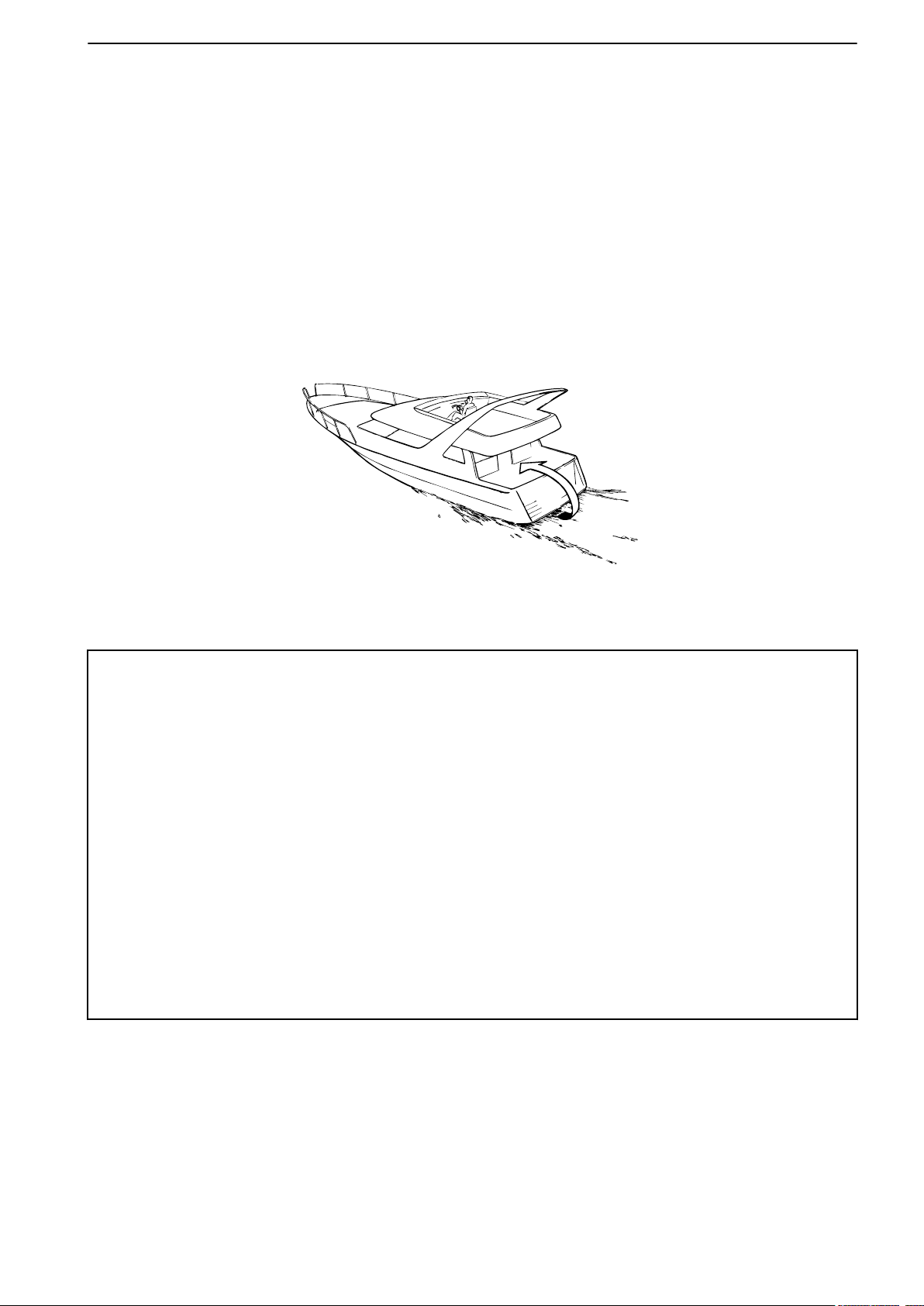
Carbon monoxide poisoning
P0003073
When a boat moves forwards, an area of low pressure
air forms behind the boat. In adverse conditions, this
low pressure can be so strong that the boat’s own
exhaust fumes are sucked into the cockpit or cabin,
which entails
all aboard.
The problem of low-pressure suction is worst in high,
wide boats with a square transom. But even in other
types of boats, low-pressure suction can be a problem
in some conditions, such as if you drive with the hood
up. Other factors which increase the low-pressure
effect are wind conditions, load distribution, pitching,
trimming, open windows and ventilators etc.
a risk of carbon monoxide poisoning for
Safety Information
Most modern boats are designed so that the problem
of low-pressure suction is very rare, however. If lowpressure suction does occur anyway, do not open
hatches or ventilators in the forward part of the boat.
Strangely enough, this makes the problem worse. Try
changing speed, trimming or load distribution instead.
Also try taking down/opening the hood or modifying it
in some other manner. Ask your boat dealer for advice
about the best solution for your particular boat.
Remember
• Safety equipment: Life jackets for everybody aboard, communication equipment, emergency
•
• Take your chart out and study your planned route. Calculate distance and fuel consumption.
• Tell your friends/relatives about route plans if you undertake a long journey. Remember to
• Inform everybody aboard about where the safety equipment is located, and how it works. Make
This list can be extended, since the need for safety equipment varies with the type of boat, and
where or how it is used etc. We recommend that you ask a regional boat or sea safety organization
for more detailed maritime safety information.
rockets, approved fire extinguisher, first aid kit, life buoy, anchor, paddle, torches etc.
Spare parts and tools: Impeller, fuel filters, fuses, tape, hose clamps, engine oil, propeller and
tools for the jobs you could be expected to have to do.
Listen to weather reports.
notify changed plans or delays.
sure that there is more than one person aboard who can start and operate the boat safely.
47705796 05-2014 © AB VOLVO PENTA 5
Page 8

Safety Information
Preparations
Knowledge
The operator’s manual contains instructions on how
to carry out general maintenance and service opera-
safely
tions
fully before starting work.
Service literature covering more complicated operations is available from your Volvo Penta dealer.
Never carry out any work on the engine if you are
unsure of how it should be done, contact your Volvo
Penta dealer who will be glad to offer assistance.
Stop the engine
Stop the engine before opening or removing engine
hatches. Unless otherwise specified all maintenance
and service must be carried out with the engine stopped.
To prevent accidental start of the boat engine, remove
the ignition key, turn off the power supply to the engine
at the main switches and lock them in the OFF position before starting work. Put up a warning sign in the
control position that work on the engine is being carried out.
Approaching or working on an engine which is running
is a safety risk. Loose clothing, hair, fingers or a dropped tool can be caught in the rotating parts of the
engine and cause serious personal injury. Volvo
Penta recommend that all servicing with the engine
running should be undertaken by an authorized Volvo
Penta workshop.
Lifting the engine
When lifting the engine, use the lifting eyes installed
on the engine. Always check that lifting equipment is
in good condition and has sufficient load capacity to
lift the engine (engine weight including any extra
equipment installed). For safety’s sake lift the engine
using an adjustable lifting beam. All chains and cables
should run parallel to each other and as perpendicular
as possible in relation to the top of the engine. Bear
in mind that extra equipment installed on the engine
may alter its center of gravity. Special lifting equipment may then be required in order to maintain the
correct balance and make the engine safe to handle.
Never carry out work on an engine suspended on a
hoist.
and correctly. Read the instructions care-
Before starting the engine
Reinstall all protective parts removed during service
operations before starting the engine. Check that no
tools or other items have been left on the engine.
Never start a turbocharged engine without installing
the air
Turbocharger unit can cause serious personal injury.
Foreign objects can also be sucked in and cause
mechanical damage to the unit.
cleaner (ACL). The rotating compressor in the
Fire and explosion
Fuel and lubrication oil
All fuel, most lubricants and many chemicals are
inflammable. Read and follow the instructions on the
packaging.
When carrying out work on the fuel system, make sure
the engine is cold. A fuel spill onto a hot surface or
electrical components can cause a fire.
Store fuel soaked rags and other flammable material
so that there is no danger of them catching fire. Fuelsoaked rags can self-ignite under certain conditions.
Do not smoke when filling fuel, oil or in proximity of a
filling station or in the engine room.
Non-original components
Components used in the fuel and electrical systems
on Volvo Penta products are designed and constructed to minimize the risk of fire and explosion.
Using non-original Volvo Penta parts can result in fire
or explosion on board.
Batteries
The batteries contain and emit oxyhydrogen gas,
especially during charging. This gas is easily ignited
and highly volatile.
Do not under any circumstances smoke or use naked
flame or allow sparks in the vicinity of the batteries or
battery compartment.
An incorrect connection of a battery terminal cable or
jump-start cable can cause a spark which in its turn
can be sufficient to cause an explosion.
Start spray
Never use start spray or similar agents to start an
engine equipped with air pre-heating (glow plugs/
starter element). This may cause an explosion in the
inlet manifold. Danger of personal injury.
6 47705796 05-2014 © AB VOLVO PENTA
Page 9

Safety Information
Hot surfaces and fluids
There is always a risk of burns when working with a
hot
engine.
exhaust pipe, turbo unit, oil pan, charge air pipe,
starter element, hot coolant and hot oil in oil lines and
hoses.
Beware of hot surfaces. For example: the
Carbon monoxide poisoning
Only start the engine in a well-ventilated area. If operating the engine in an enclosed space, ensure that
there is proper ventilation in order to remove exhaust
gases and crankcase ventilation emissions from the
working area.
Chemicals
Most chemicals such as anti-freeze, rustproofing
agent, inhibiting oil, degreasing agent etc. are hazardous to health. Read and follow the instructions on
the packaging.
Some chemicals such as inhibiting oil are inflammable
and dangerous if breathed in as well. Ensure good
ventilation and use a protective mask when spraying.
Read and follow the instructions on the packaging.
Store chemicals and other hazardous materials out of
the reach of children. To protect the environment,
please dispose of used or leftover chemicals at a
properly designated disposal site for destruction.
Cooling system
There is a risk of flooding when working on the seawater system. Turn off the engine and close the sea
cock before starting work on the system.
Avoid opening the coolant filler cap when the engine
is hot. Steam or hot coolant can spray out and cause
burns.
Fuel system
Always
uids ejected under pressure can penetrate body tissue and cause serious injury. There is a danger of
blood poisoning.
Always cover the generator if it is located under the
fuel filter. The generator can be damaged by spilled
fuel.
use protective gloves when tracing leaks. Liq-
Steering system
The boat has a advanced steering system. DO NOT
change connectors, wiring or splice of the components.
Service must be done by approved workshops which
have certifed personnel with qualified professional
training.
Electrical system
Cutting off power
Always stop the engine and break the current using
the main switches before working on the electrical
system. Isolate shore current to the engine block
heater, battery charger, or accessories mounted on
the engine.
Batteries
The batteries contain an extremely corrosive electrolyte. Protect your skin and clothes when charging or
handling batteries. Always use protective goggles and
gloves.
If battery electrolyte comes into contact with unprotected skin, wash off immediately using plenty of
water and soap. If battery acid comes into contact with
the eyes, flush immediately with plenty of water and
obtain medical assistance without delay.
If work must be carried out with the engine at operating temperature and the coolant filler cap or a cock
open or a coolant hose disconnected, open the coolant filler cap carefully and slowly to release pressure
before removing the cap completely. Note that the
coolant may still be hot and can cause burns.
Lubrication system
Hot oil can cause burns. Avoid skin contact with hot
oil. Ensure that the lubrication system is not under
pressure before commencing work on it. Never start
or operate the engine with the oil filler cap removed,
oil can spray out.
47705796 05-2014 © AB VOLVO PENTA 7
Page 10

Introduction
This Operator's Manual has been prepared to give you the greatest possible benefit from your Volvo Penta marine
engine. It contains the information you need to be able to operate and maintain the engine safely and correctly.
Please read the Operator's Manual carefully and learn to handle the engine, controls and other equipment in a
safe manner before you cast off on your maiden voyage.
Always have the Operator's Manual available. Store it safely and do not forget to hand it over to the next owner
if you sell your boat.
The Operator’s Manual describes the engine and equipment sold by Volvo Penta. The illustrations in this book
covers several
different controls and instrumentation might occur, in these cases we refer to this products manual.
Warranty
Your new Volvo Penta marine engine is covered by a
limited warranty, under the conditions compiled in the
Warranty Information.
Please note that AB Volvo Penta’s liability is limited to
the specification in the Warranty Information. Read it
carefully, as soon as possible after delivery. It
includes important information about service, maintenance, which it is the responsibility of the owner to
know, check and carry out. If this is not done, AB Volvo
Penta may fully or partly refuse to honour its warranty
undertakings.
Please contact your Volvo Penta dealer if you
have not received the Warranty Information or
Service Book.
Environmental care
All of us want to live in a clean, healthy environment.
Where we can breathe clean air, see healthy trees,
have clean water in lakes and seas, and be able to
enjoy the sunlight without fearing for our health.
Unfortunately, this is not self-evident these days, it is
something all of us must work hard for.
As a manufacturer of marine engines, Volvo Penta
has particular responsibility and for this reason, environmental care is a core value in our product development. Volvo Penta has a wide engine programme
these days, where considerable progress has been
made in reducing exhaust fumes, fuel consumption,
engine noise etc.
We hope that you will be want to preserve these values. Always observe the advice in the Operator's
Manual about fuel grades, operation and maintenance, to avoid unnecessary environmental impact.
Please contact your Volvo Penta dealer if you notice
any changes such as increased fuel consumption or
increased exhaust smoke.
varieties and might differ, the essential information is always correct though. Installations with e.g.
Moderate your speed and distance so that wake and
noise do not disturb or damage animal life, moored
boats, jetties etc. Leave the archipelago and harbours
in the same state you would like to find them. Remember to always hand in drained oil, coolant, paint and
wash residue, used batteries etc. for destruction at a
recycling station.
If we all pull together, we can make a valuable contribution to the environment together.
Running in
The engine must be “run in” during its first 10 hours,
as follows:
Use the engine in normal operation. Full load should
only be applied for short periods. Never run the engine
for a long period of time at constant speed during this
period.
Higher oil consumption is normal during the running
in period. For this reason, check the oil level more
frequently than normally recommended.
After the first period of operation, the specified warranty inspection “First service inspection” can be
done. For more information: Please refer to the Maintenance Schedule.
Fuel and oils
Only use the fuels and oils recommended in the Operator's Manual. Other grades can cause malfunctions,
increased fuel consumption and eventually even
shorten the life of the engine.
Always change the oil, oil filters and fuel filter at the
specified intervals.
8 47705796 05-2014 © AB VOLVO PENTA
Page 11

Introduction
Service and spare parts
Volvo Penta marine engines are designed for high
reliability and long life. They are built to withstand a
marine environment, but also to have the smallest
possible
ice and use of by Volvo Penta approved spare parts,
these qualities are retained.
Volvo Penta’s world-wide network of authorised dealers is at your service. They are Volvo Penta product
specialists, and have the accessories, original spares,
test equipment and special tools needed for high quality service and repair work.
Always observe the maintenance intervals in the
Operator's manual, and remember to note the engine/
transmission identification number when you order
service and spare parts.
environmental
impact. Through regular serv-
Recording engine data
One or more computers in your Volvo Penta engine
can record detailed information. It can include data
such as usage and information of other systems and
modules on the engine. This data can include information such as boat position and usage. Only a limited amount of data can be stored.
AB Volvo Penta will not distribute this stored information without permission. AB Volvo Penta may, however, be forced to provide this information if required
by national legislation. In general, AB Volvo Penta and
authorised workshops may read and use the information.
Certified engines
If you own or operate an emission certified engine it
is important to be aware of the following:
Certification means that an engine type has been
checked and approved by the relevant authority. The
engine manufacturer guarantees that all engines
made of the same type are equivalent to the certified
engine.
This makes special demands on the care and
maintenance you give your engine, as follows:
• Maintenance and service intervals recommended by Volvo Penta must be complied with.
• Only by Volvo Penta approved spares may be
used..
• Service on injection pumps, pump settings and
injectors must always be done by an authorised
Volvo Penta workshop.
• The engine must not be converted or modified,
except for the accessories and service kits
which Volvo Penta has approved for the engine.
• Installation changes to the exhaust pipe and
engine air inlet ducts must not be done.
• No seals may be broken by unauthorised personnel.
The general advice in the Operator's manual about
operation, care and maintenance apply.
Volvo Penta Electronic Vessel Control
system (EVC) Integrity and Modification
The EVC system is a complete vessel control system
for engine, gear and vessel steering control. The complete EVC system is developed, tested and verified to
comply with Volvo Penta’s stringent requirements for
safety and reliability based on approved standard configurations. In order to maintain the EVC system integrity, all interaction with external systems (e.g., autopilot) is performed via Volvo Penta designed interfaces.
After-market interfaces breach system integrity and
may negatively affect vessel performance, safety and
warranty coverage. Volvo Penta does not endorse
any direct or indirect connection with other systems or
components not being fully tested, verified and
approved in writing by Volvo Penta. Volvo Penta
accepts no responsibility for modification of the Volvo
Penta EVC system and/or use of components or interfaces not sold or approved by Volvo Penta.
Late or inadequate maintenance/service or the use of
spare parts not approved by Volvo Penta will invalidate AB Volvo Penta’s responsibility for the engine
specification being in accordance with the certificated
variant.
Volvo Penta accepts no responsibility or liability for
any damage or costs arising due to the above.
47705796 05-2014 © AB VOLVO PENTA 9
Page 12
Instruments and Controls
This chapter describes the instruments, panels and controls Volvo Penta sells for your engine.
If you would like to complement your instrumentation, or if your boat is equipped with instruments not described
here, we ask that you contact your Volvo Penta dealer.
For information about screens from 8” and above, please refer to the separate manual for Volvo Penta Glass
Cockpit.
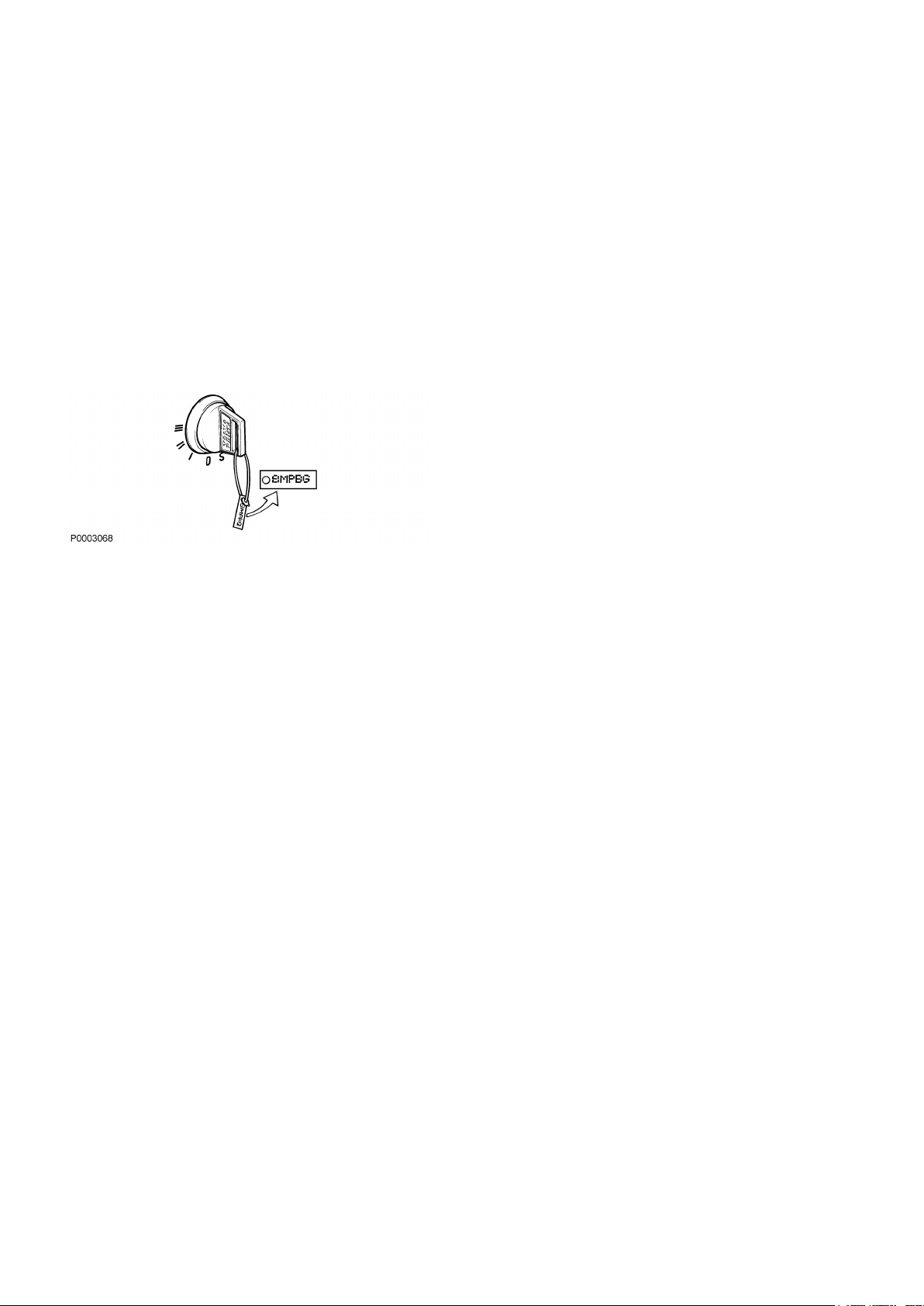
Ignition Lock
The start keys are supplied with a plate bearing the
start code
the code beyond the reach of unauthorized people.
S = The stop position.
0 = The key can be inserted or removed.
I = Operating position. System power is connected.
II = Not used.
III = Start position. Starter motor is engaged.
There is always a helm station with an ignition lock.
The ignition
helm stations to be used.
Read the starting instructions in the Starting page 56
chapter to make sure you use the correct start procedure.
to be used when ordering spare keys. Keep
must be switched on here in order for other
Control Panels
Volvo Penta panels and gauges can be installed in different combinations. There is always one information
panel per driveline and helm station if no 7" screen is
installed. The control panels can be used together with
the tachometer and other accessory equipment.
10 47705796 05-2014 © AB VOLVO PENTA
Page 13
P0001306
Instruments and Controls
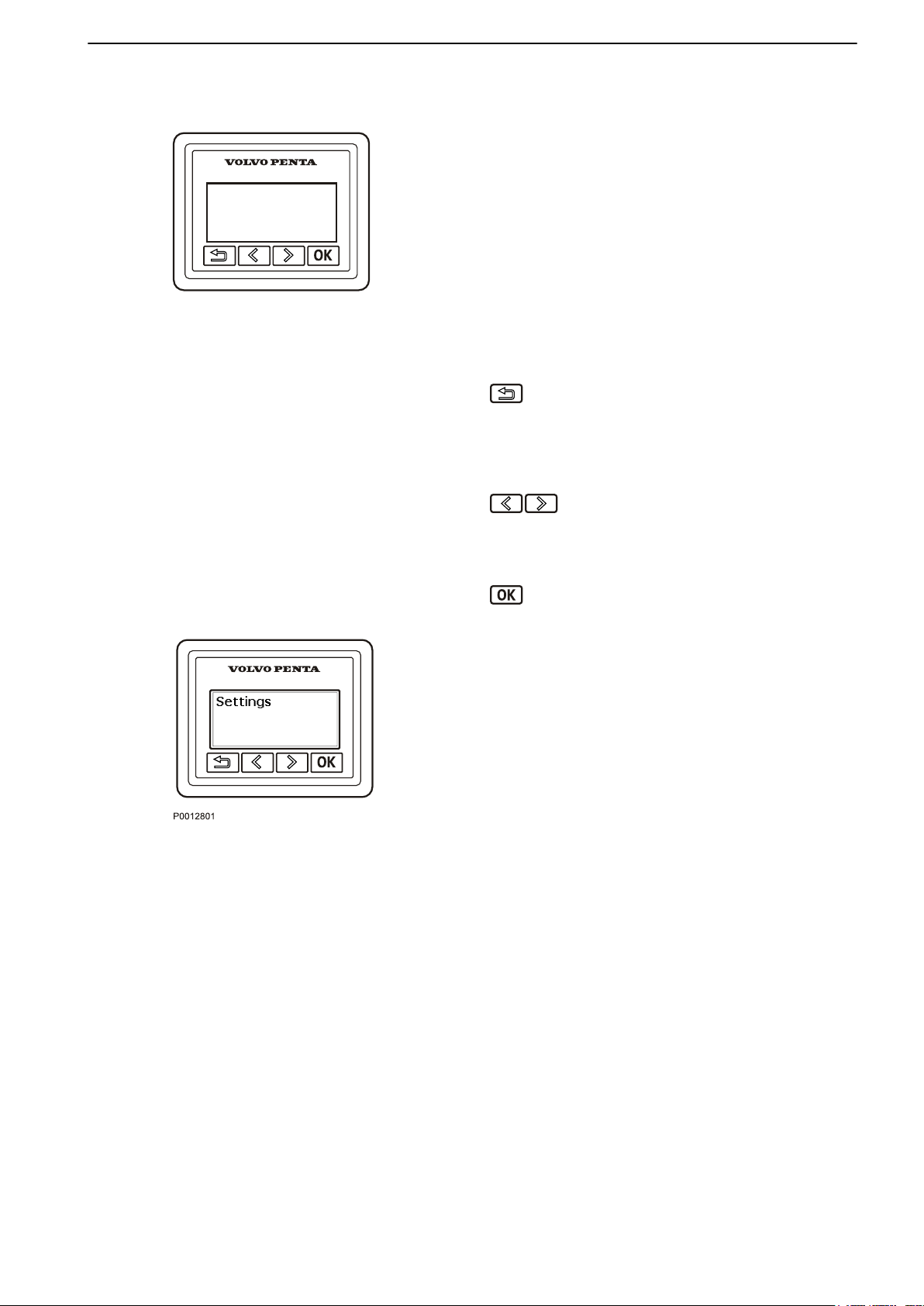
Information Panel
The information panel shows engine and operational
information, messages and alarms.
There is one information panel per driveline and helm
station if no 7" screen is installed.
The information
sonal preferences. Basic settings show:
Engine speed
•
Oil pressure
•
Coolant temp
•
Battery voltage
•
Return to the previous menu by pressing the button.
Hold the
the main menu or browse back to it by pressing the
button repeatedly.
button down for more that 3 seconds to reach
shown can be set up according to per-
Browse backwards and forwards through the information panel menus by pressing the buttons.
Hold down a button to scroll through a menu.
Confirm a selection by pressing the button.
Settings
Browse to the settings menu and press “OK” to proceed to the submenu.
For further information about settings, refer to Settings
Menu page 120.
To adapt information shown in the main menu to suit
your personal preferences, refer to My
View page 120.
47705796 05-2014 © AB VOLVO PENTA 11
Page 14

P0001259
P0002114
Instruments and Controls
Fault messages
If the system discovers a fault, the word Fault is displayed on
detected, press “OK”.
For further information on how to handle fault messages and recommended actions, refer to the Fault
Handling page 67 chapter.
Backlighting
Panel backlighting can be adjusted by pressing
the screen. To see the what faults have been
simultaneously.
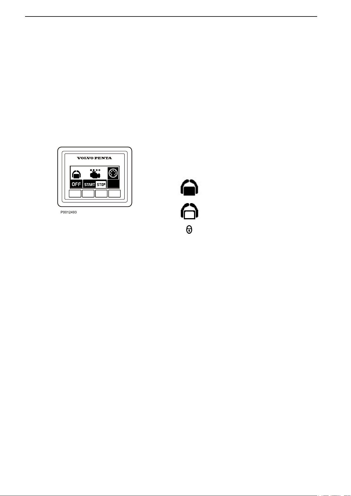
Start/Stop Panel
The start/stop panel is used for starting and stopping
the engine from stations without a start key.
To start the engine it is necessary for the start key to
be in the ”I” operating position.
Read the starting instructions in chapter
Starting page 56 and Engine Shutdown page
ensure you use the correct start procedure.
64
to
Cruise Control
Switch on cruise control by pressing the
Make fine adjustments to the locked engine speed by
pressing the + or – buttons to increase or reduce it.
button.
Sport fish panel
Sport fishing
Single lever
Silent idle
For more information regarding these functions, refer
to the Optional page 37
section.
12 47705796 05-2014 © AB VOLVO PENTA
Page 15

P0001088
Instruments and Controls
Station Panel
Activation
Activate the
ton. Further pressure locks the helm station.
To render the helm station inactive, hold the button
down for 3 seconds.
helm station with a single press of the but-
Inactive helm station
For further information about the function, refer to
chapter Optional page 36.
The gearshift
control lever only operates the throttle. The neutral
button disengages the drive/reverse gear so that
engine speed may be increased without driving the
boat; (warm-up mode).
When the single-lever function is activated, the lever
that is moved from its position first becomes the control
lever for both engines. The other control lever has no
function as long as the single-lever function is activated.
Active helm station
Locked helm station
Low speed
Neutral button
function can be disconnected so that the
The drive is disengaged.
Drive engaged for movement ahead/astern.
Single lever
47705796 05-2014 © AB VOLVO PENTA 13
Page 16
Instruments and Controls
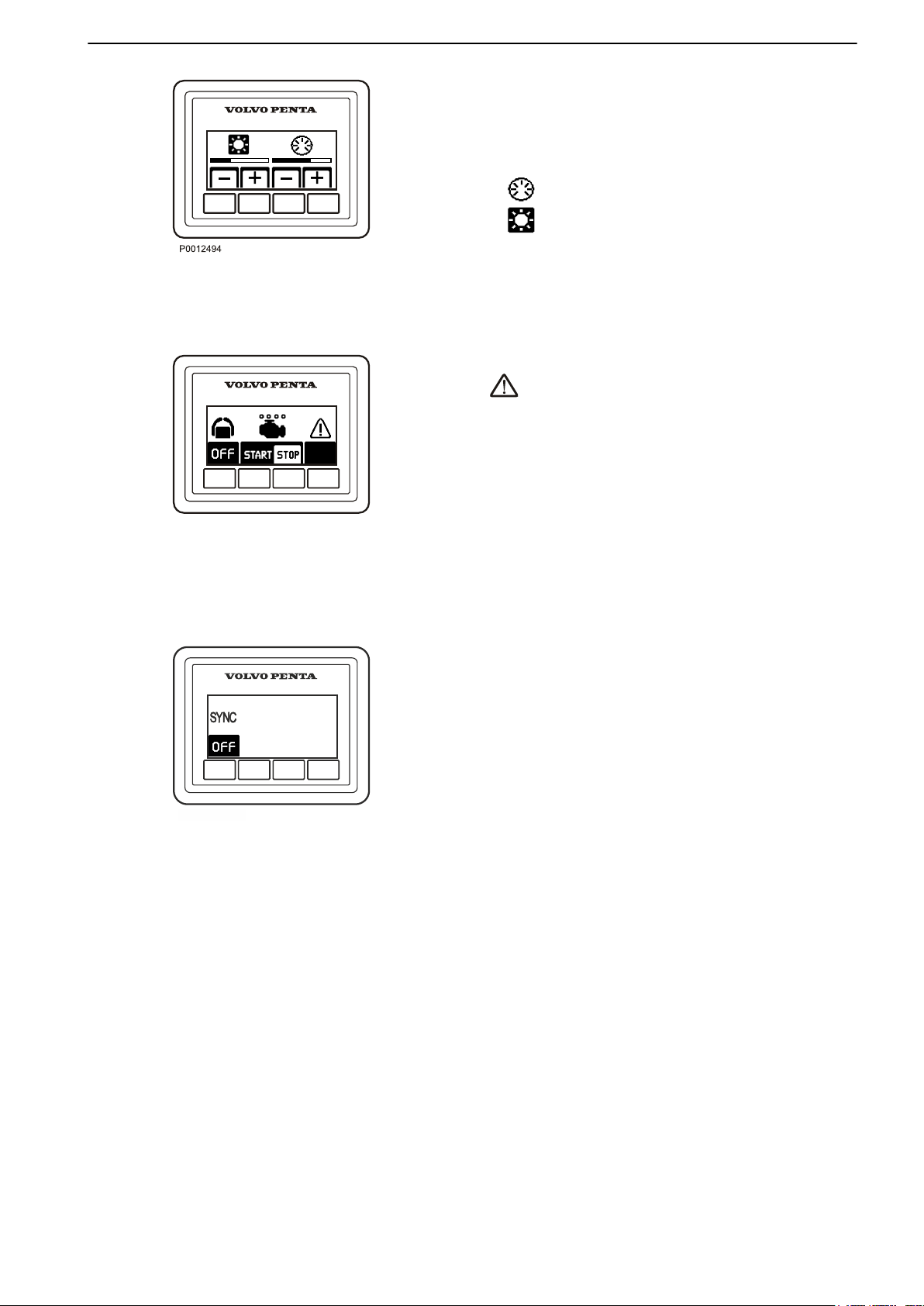
Docking Panel
When the boat is operated from a docking station
engines, can be stopped and started and messages
can be managed using the docking panel.
The joystick can be used for maneuvering when the
docking station is activated; refer to the Joystick section for further information.
Activation
Activate the
ton. A further pressure on the button locks the helm
station.
To switch off the function, hold the button down for 3
seconds.
Twin instalation
Both engines in a twin instalation must be running
before the docking station can be activated.
helm station by depressing the on/off but-
The helm station is inactive.
The helm station is active and the docking
function is switched on.
The helm station is locked.
Start/Stop
Press the STOP and START buttons to stop and start
all engines.
The circles above the engine symbols show which
engines are running. An empty circle means an engine
is running.
14 47705796 05-2014 © AB VOLVO PENTA
Page 17
P0001308
P 1992300
Instruments and Controls
Contrast and backlighting
The button on the far right is used to adjust contrast
and panel
firm fault messages.
Press the button to adjust the contrast and the backlighting.
Use
lighting.
Adjustments affect all screens in the system.
Fault message
covers a fault.
All fault messages must be acknowledged. Acknowledge by
by an audible signal, the signal will silenced. Go to the
information panel to get information regarding the
alarm.
backlighting. The button is also used to con-
Backlighting
Contrast
+
and – to increase or reduce the contrast or back-
is displayed on the screen when the system dis-
pressing the button; if the fault is accompanied
For further information on how to handle fault messages and recommended actions, refer to the Fault
Handling page 67 and Fault Code Register chapters.
Syncronisation panel
The engine synchronization function can be switched
off at the synchronization panel to allow engine speeds
to be controlled independently. In triple installations,
the midships engine receives an average of the two
outboard engines' speeds.
Switch on synchronization by pressing the button.
47705796 05-2014 © AB VOLVO PENTA 15
Page 18
0
3
2
1
4
RPMX1000
P0012490
351
h
1
P0005255
Instruments and Controls
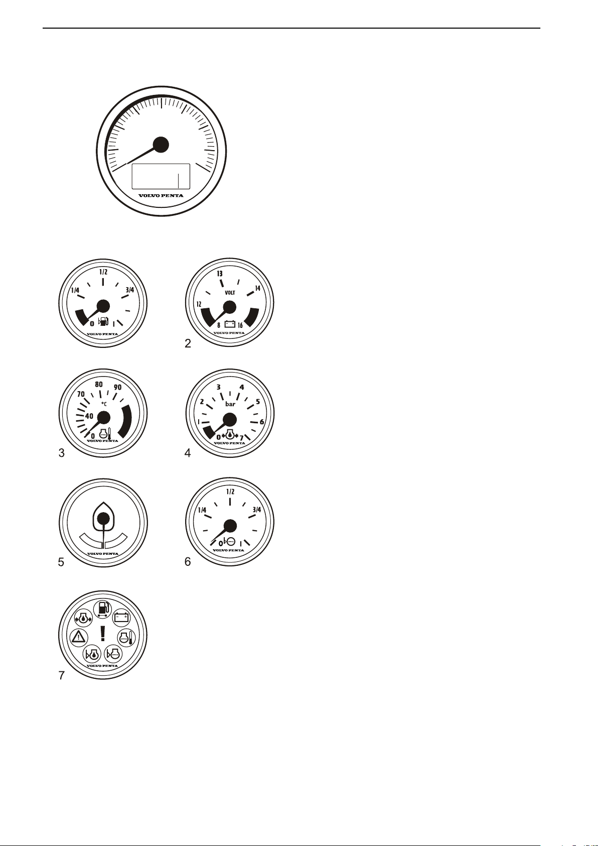
Gauges
These instruments
Penta.
The tachometer displays engine speed; multiply the
value shown on the dial by 1,000 to get the number of
engine revolutions per minute.
Engine hours is displayed in the tachometer window.
When a function is activated a symbol shows shortly in
the dispaly.
are sold as engine options by Volvo
1 Fuel level gauge
The fuel level gauge shows the quantity of remaining fuel.
2 Voltmeter, battery charging
The meter shows the alternator charge current.
During operations the charge voltage should be
around 28 V. When the engine is stopped and electrical power switched on the battery voltage should
be around 24 V.
3 Coolant temperature gauge
The instrument shows engine coolant temperature.
During operations coolant temperature should normally be between 75-90°C (167-194°F).
4 Oil pressure gauge
The oil pressure gauge displays engine oil pressure. During operations the oil pressure gauge
should normally show 3-5.5 bar (43.5-79.8 PSI). At
idle, lower values are normal.
5 Rudder position indicator
The instrument shows rudder position.
6 Fresh water level sensor
Freshwater tank level gauge.
7 Alarm monitor
The alarm monitor gives a visual warning to call
attention to any alarms that occur.
16 47705796 05-2014 © AB VOLVO PENTA
Page 19
P0001101
Instruments and Controls
4" Display
IMPORTANT!
Make a habit of protecting the screen with the protective cover
sure to strong sunlight can damage the screen and
cause function faults.
The Volvo Penta 4" screen is controlled by means of
buttons on the panel:
button.
The image reverts automatically a short while after
the button is released.
play. Scroll
pressing the appropriate button.
when the boat is not in use. Prolonged expo-
Return to the previous menu by pressing the
Press the button to adjust the display contrast.
Menu button functions are shown on the dis-
back and forth or confirm a selection by
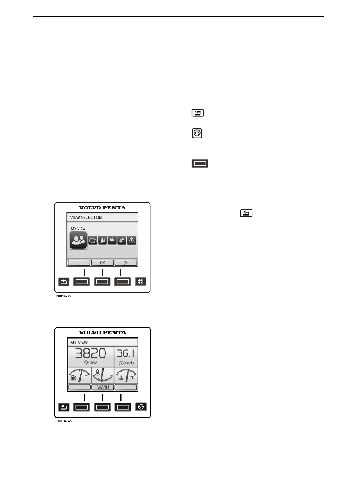
View Selection
View Selection
The last selected view is shown on start. To return to
the main menu, click
screen using the arrow buttons.
My Viewoperating information
•
Engine Viewengine information
•
Fuel economytrip computer
•
Vesselinformation regarding the boat's engine
•
installation
Settingssettings, display and installed functions
•
Warning Managershows system faults detected
•
and describes remedial actions
. Navigate to the desired
My View
Gauge and operations information is shown in the My
View window.
Some functions
can be switched on/off by pressing OK.
To change the gauge and information shown, refer to
Change gauge. Functions are also switched on and off
here.
are pre-set as quick selections. These
My View
47705796 05-2014 © AB VOLVO PENTA 17
Page 20
Instruments and Controls
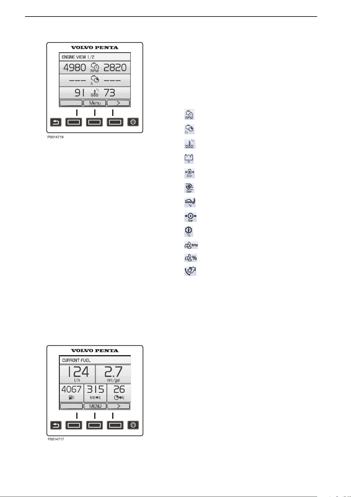
Engine View
Engine View
Information
shown in Engine View. The information is shown in two
windows; switch between the windows by pressing the
arrow buttons.
Up to six different pieces of operations data can be
shown on the display. The information shown can be
set under Change gauge.
Depending on the functions installed in the boat, the
following can be displayed:
concerning
Engine speed
Engine hours
Engine Coolant Temperature
the engine and transmission is
Battery Voltage
Engine oil pressure
Turbo pressure
Exhaust Temperature
Transmission Oil Pressure
Transmission oil temperature
Propeller Rotation
Propulsion
Power Trim angle
Fuel
This is the boat's trip computer and information is
shown in
Switch between screens by pressing the arrow buttons.
Current Fuel
•
•
•
two windows, Current Fuel and Average fuel.
Instant fuel ratecurrent fuel consumption per hour.
Instant fuel economybased on current fuel con-
sumption.
Remaining in tankamount of fuel remaining in the
tank.
Distance remainingtrip distance with fuel remain-
•
ing in the tank based on current fuel consumption.
Time to emptyoperating time with fuel remaining in
•
the tank based on current fuel consumption.
Current Fuel
18 47705796 05-2014 © AB VOLVO PENTA
Page 21
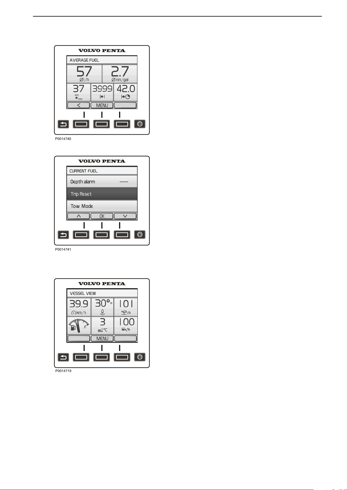
Average fuel
Instruments and Controls
Average fuel
Average fuel rateaverage fuel consumption since
•
the last trip computer zero reset.
Average fuel economyaverage since the last trip
•
computer zero reset.
Trip distancedistance traveled since the last trip
•
computer zero reset.
Trip fuelused quantity since the last trip computer
•
zero reset.
Trip hourstime since the last trip computer zero
•
reset.
Trip Computer Reset
zero
To
button and select Trip Reset.
all values in the trip computer, press the MENU
Trip Computer Reset
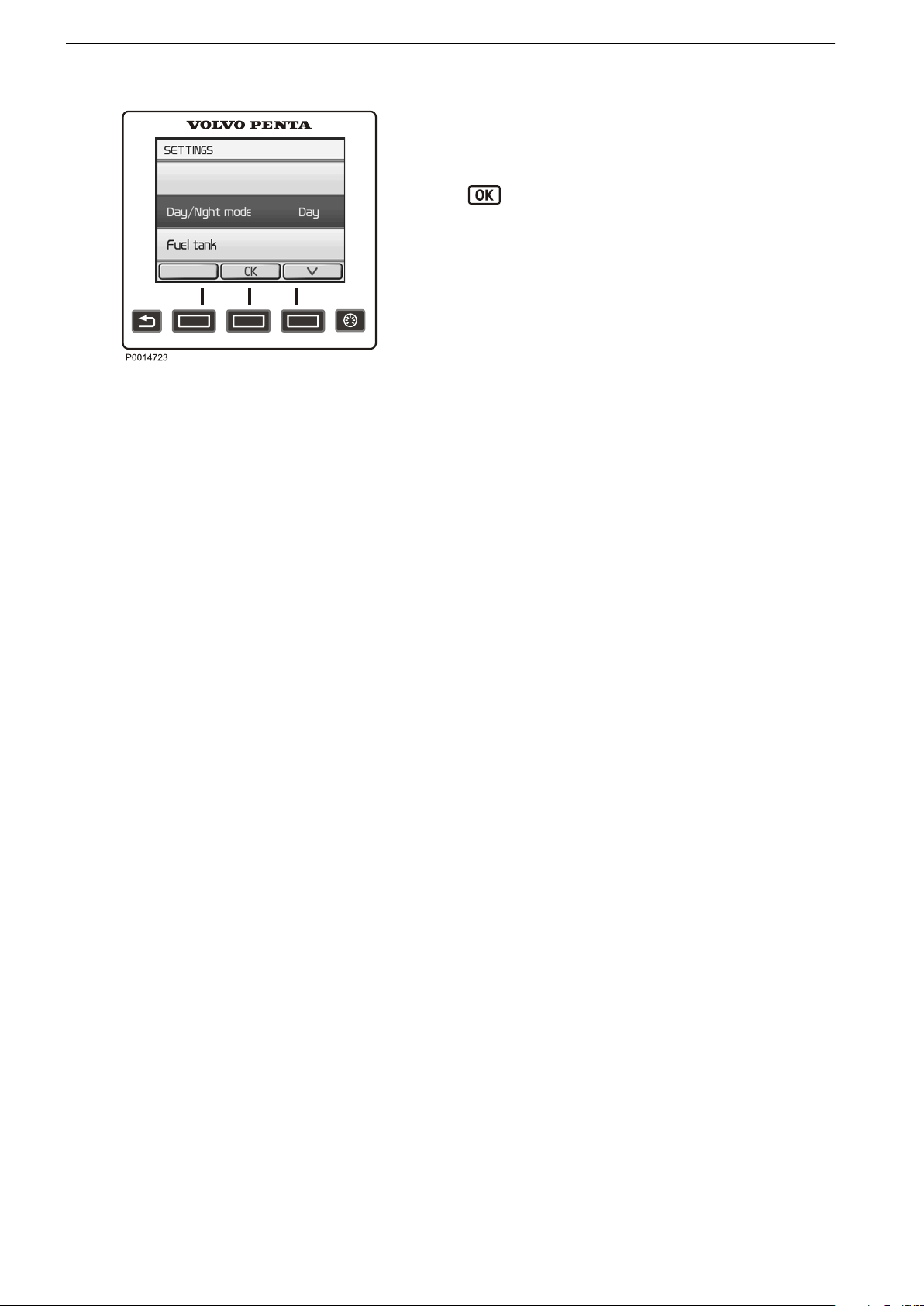
Vessel
Vessel
Shows information regarding the boat's installation.
The information shown can be set under Change
gauge. Functions are also switched on and off here.
Depending on the functions installed in the boat, the
following can be displayed:
Boat Speed
•
Rudder angle
•
Depthfor setting echo sounder, refer to Depth
•
Alarm page 122.
Fuel level
•
Sea water temperature
•
Freshwater level
•
ACP Infofor further information refer to
•
Optional page 53.
Interceptor positionfor further information refer to
•
Volvo Penta Interceptor System.
47705796 05-2014 © AB VOLVO PENTA 19
Page 22
Instruments and Controls
Settings
Settings
Display
various system function settings are made
and
in the settings menu. The information shown varies
depending on the installation.
Navigate to the desired setting or function and press
to reach the sub menu.
Key Managementadd and remove keys. Refer to Key
Management.
Day/Night-Mode
Day shows dark text against a light background and
Night text against a dark background.
Fuel Tank
Fuel tank calibration and settings. For information
regarding calibration, refer to Fuel Tank page 124.
Drive Type
The setting may only be made by authorized Volvo
Penta personnel.
Toe-In/Toe-Outadjustment
The setting may only be made by authorized Volvo
Penta personnel.
Neutral Beep
Switches the beeper that sounds when the control is in
the neutral position on and off.
Info Beep
Switches the signal that confirms when a function has
been activated or deactivated on and off.
Info Beeplevel
Sets the volume (%) of the Info Beepthat confirms
when a function has been activated, or deactivated.
PTA Calibration
Calibration and resetting, PTA. For information regarding calibration, refer to PTA Calibration.
Trip Reset
Zeroes all values in the trip computer.
ACP Mode
Setting the ACP protection position. For information on
the ACP function, refer to Optional page 53.
Depth Alarm
When setting the depth alarm function; refer to Depth
Alarm page 122.
Display Contrast
Contrast adjustments affect all displays in the system.
Display Type
Select the engines for which the information will be
shown in the display, and the type of installation the
display forms part of.
20 47705796 05-2014 © AB VOLVO PENTA
Page 23
Instruments and Controls
Units
Setting the
units (metric, US or Imperial) and distance
units (km, NM or miles) that distances will be shown in.
Language
Setting the language that information will be shown in.
Speed Factor
When setting the speed factor, refer to Speed
Factor page 125.
EVC Information
Information about components, software and functions
installed. Installed functions are checkmarked.
Service
The drive is fitted with a sensor that monitors oil level
and quality. If the oil level in the drive is low or if there
is water in the oil, the helmsman is alerted by an audible alarm and a message is shown on the display
simultaneously. Every time oil is changed, the waterin-oil sensor must be calibrated; refer to
Service page 121
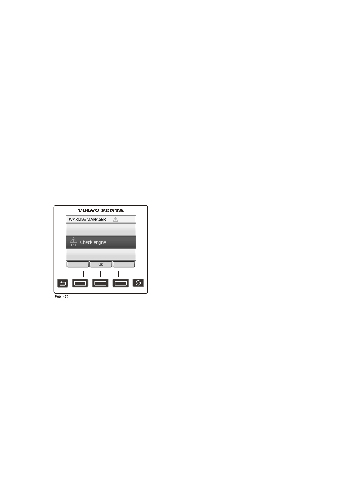
Warning Manager
Warning Manager
If the system discovers a fault, the helmsman is alerted
by a message on the display. The fault message must
be acknowledged by pressing OK.
All fault messages are stored in Warning Manager, the
drivetrain affected is also shown, the fault described
and suitable actions suggested. For further information
on the fault messages concerned, refer to Fault Code
Register page 71.
47705796 05-2014 © AB VOLVO PENTA 21
Page 24
Instruments and Controls
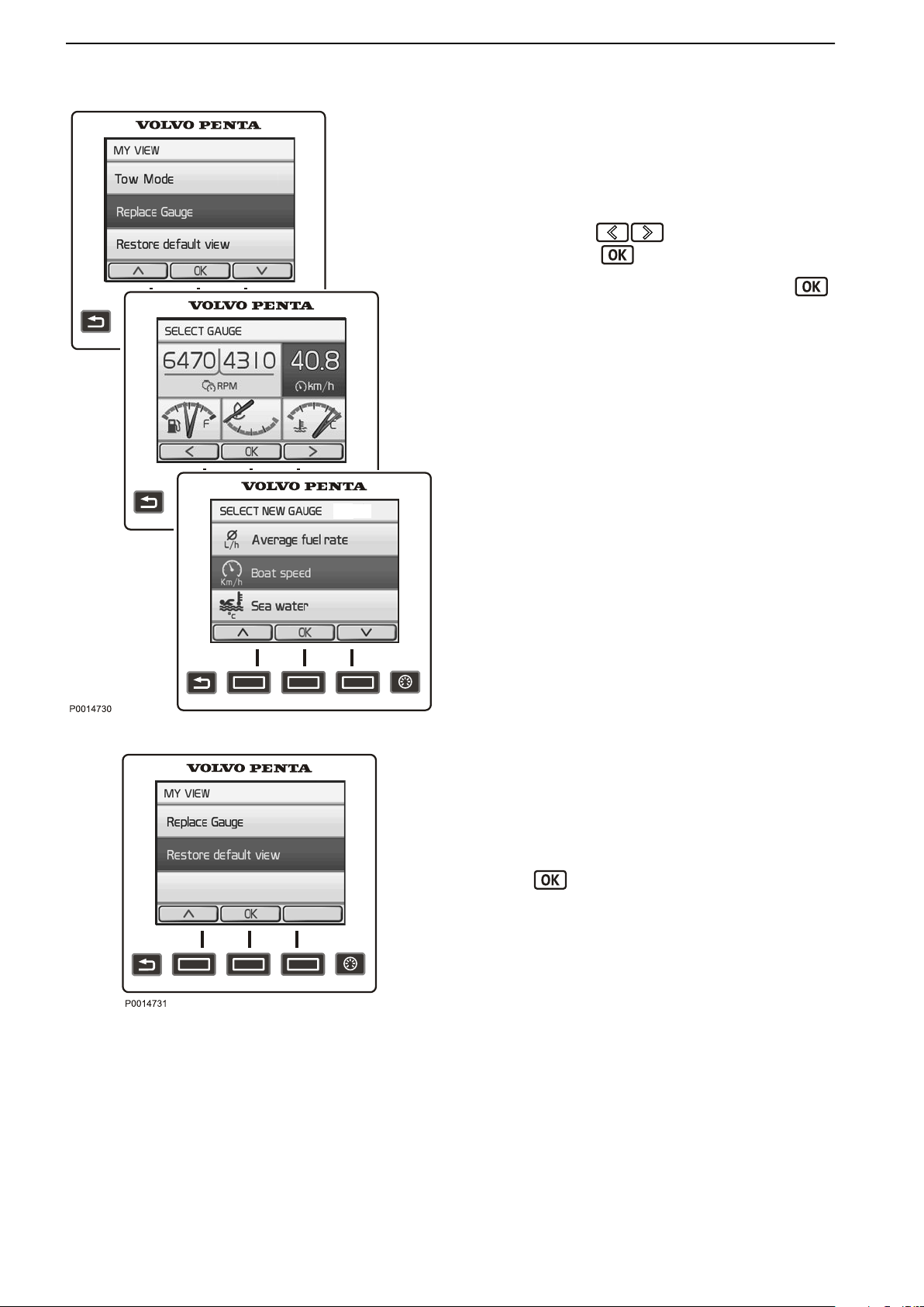
Replace gauge
In the views My View, Engine View and Vessel, the
owner can decide what information will be shown
where on the display. The procedure is the same for
all views.
1 Press
2
Navigate using
MENU button and select Replace gauge.
the
to the gauge for replace-
ment and press .
3
Select the gauge for replacement and press .
Replace gauge
Restore Default View
Restore Default View
The display has a basic setting that it is always possible to return to.
the
1 Press
MENU button and select Restore Default
View.
2
Press
.
22 47705796 05-2014 © AB VOLVO PENTA
Page 25
OK
P0001101
OK
P0001165
2
1
P0001050
Instruments and Controls
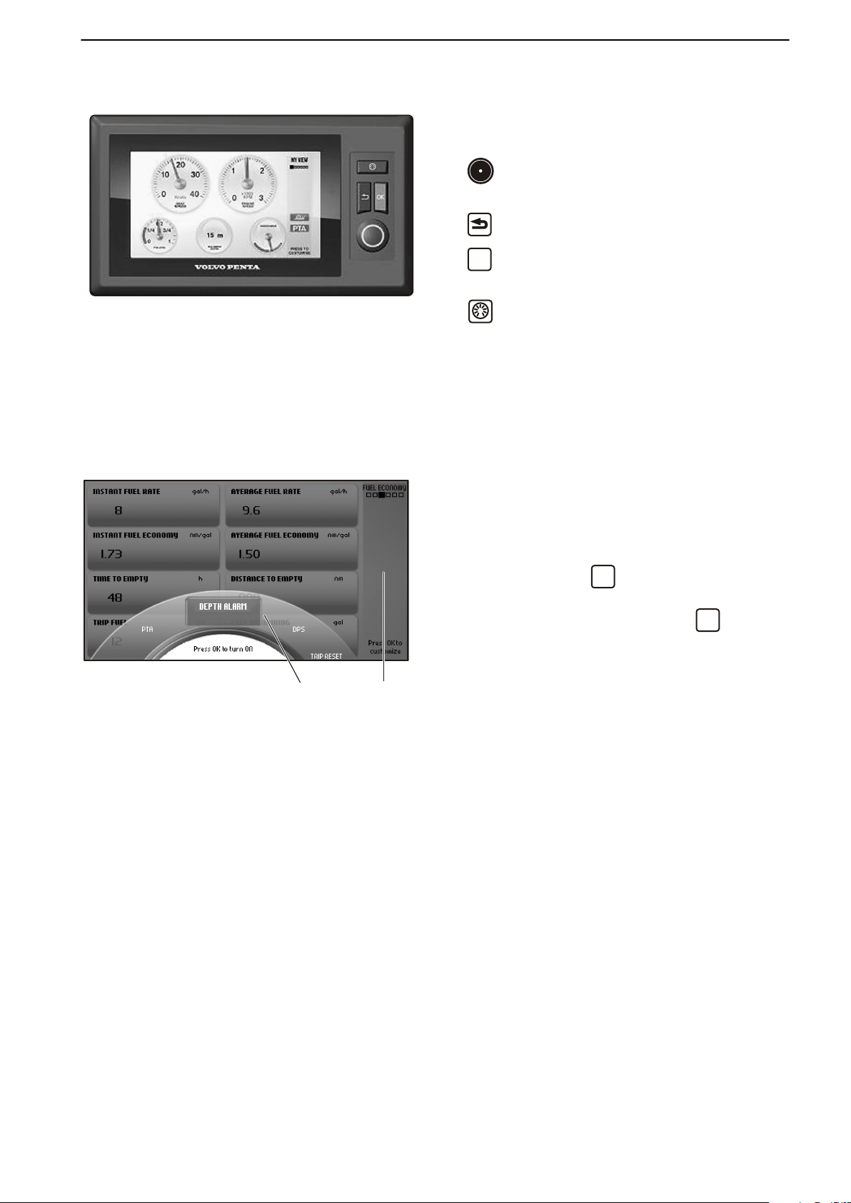
7" Display
The Volvo Penta 7" screen is controlled by means of
buttons:
Turn to browse through submenus and to return
to the main menu.
Return to the previous menu.
Confirms selection; also used to access sub-
menus and the Settings page 29
Controls boat instrument backlighting. The
page automatically returns a few seconds after the
button is released.
IMPORTANT!
Make a habit of protecting the screen with the protective cover
when the boat is not in use. Prolonged exposure to strong sunlight can damage the screen and
cause function faults.
.
1 Pop-up menu
2 Status field
The status field (2) on the right of the screen displays
the current view, active functions and repaired faults.
Pop-up
A number of pre-set functions can be switched on and
off in a pop-up. Press
and the functions will show
in the lower part of the screen (1).
Turn to the desired function and press OK to confirm
that the function is to be switched on or off.
Active functions
are displayed by a symbol in he status
field (2) on the right.
Trip Reset is also found here; refer to Fuel
economy page 27.
47705796 05-2014 © AB VOLVO PENTA 23
Page 26
OK
OK
OK
P0012481
P0001187
P0001188
Instruments and Controls
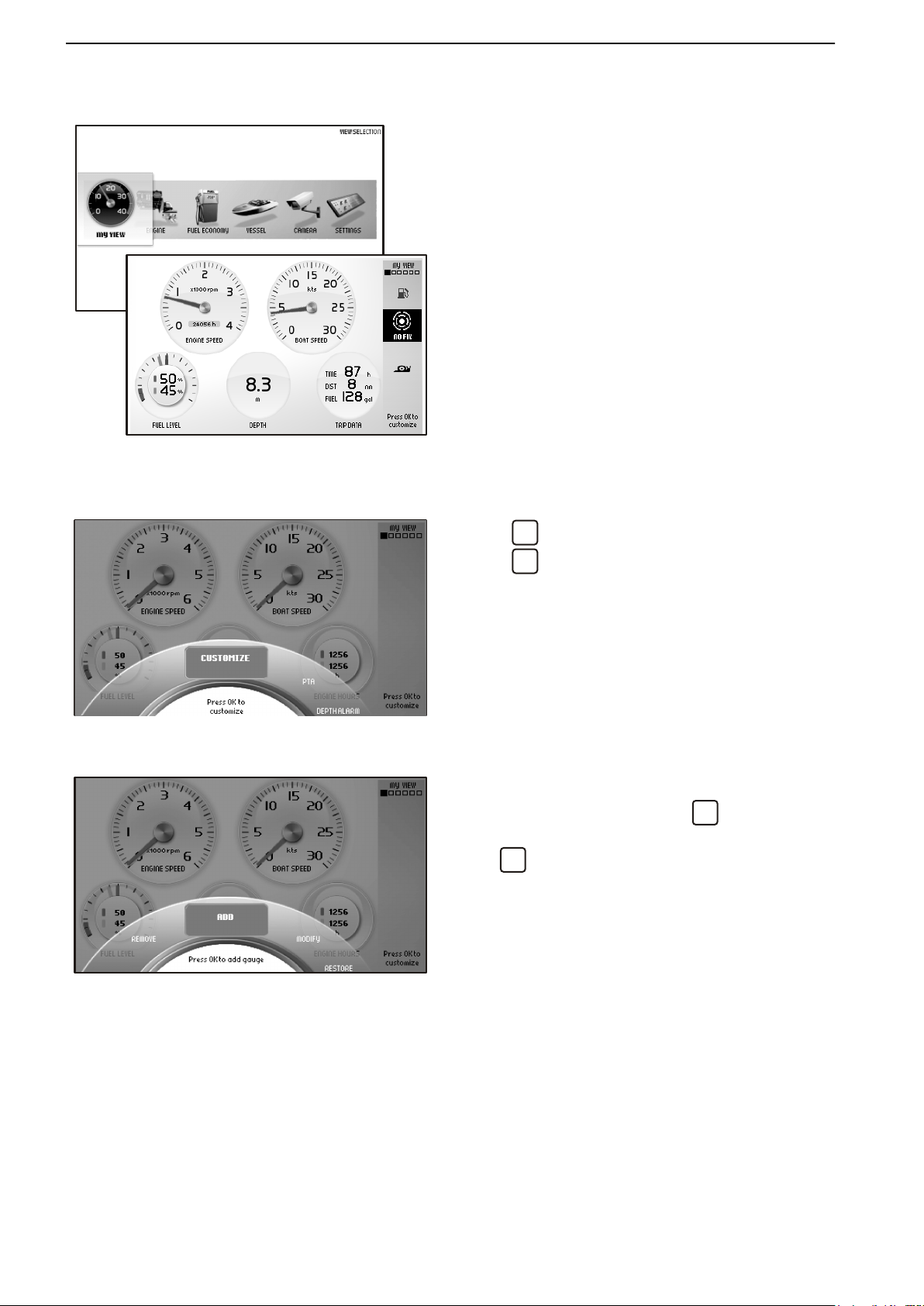
My View
Boat, engine and transmission data are displayed in
My View as analog or digital instruments.
Selection of instruments to be displayed and their
appearance is made under the Customize menu.
Information for up to three engines can be displayed
same screen in boats with multiple engine instal-
on the
lations; they are distinguished by different color dials
in the instruments.
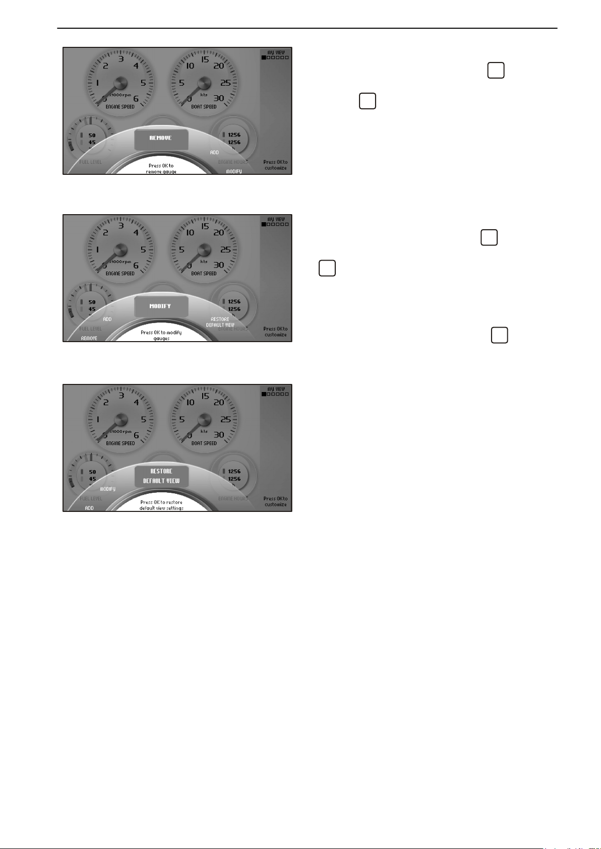
Customize
Press
so that the Customize menu is displayed.
Press OK to access the submenus Add, Remove,
Modify and Return to basic setting..
Use the knob to browse between menus.
Adding instruments
Turn the knob to
Select
with
the
. The new instrument will position itself at the
Add and press
desired information is displayed and confirm
bottom right corner.
.
24 47705796 05-2014 © AB VOLVO PENTA
Page 27
OK
OK
OK
P0001184
P0001185
P0001097
Instruments and Controls
Removing instruments
Turn to the Remove menu and press OK.
Turn to the instrument that is to be removed and con-
firm with OK.
Changing instruments
Turn to the Modify menu and press
.
Select the instrument that is to be changed and press
.
Choose between:
Remove, removes the instrument.
Replace, changes
to the desired instrument and press
one instrument for another. Turn
.
Analogue/Numeric, specify whether the instrument will be displayed as analog or digital.
Restore Default View
The screen has a basic setting that can always be
returned to by pressing Restore Default View in the
Customize menu.
47705796 05-2014 © AB VOLVO PENTA 25
Page 28
P0012483
Instruments and Controls
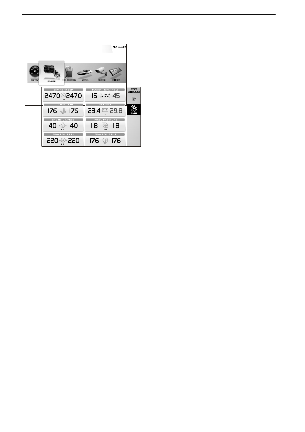
Engine
Information concerning
is displayed in this view.
Depending on the functions installed in the boat, the
following can be displayed:
- Engine Speed
- Rudder angle
- Coolant Temperature
- Voltage battery voltage
- Engine oil pressure
- Turbo pressure
- Engine hours, total operating hours.
- Transmission Oil Pressure
- Transmission oil temperature
The information in this view cannot be changed.
the engine and its transmission
26 47705796 05-2014 © AB VOLVO PENTA
Page 29
OK
P0012482
Instruments and Controls
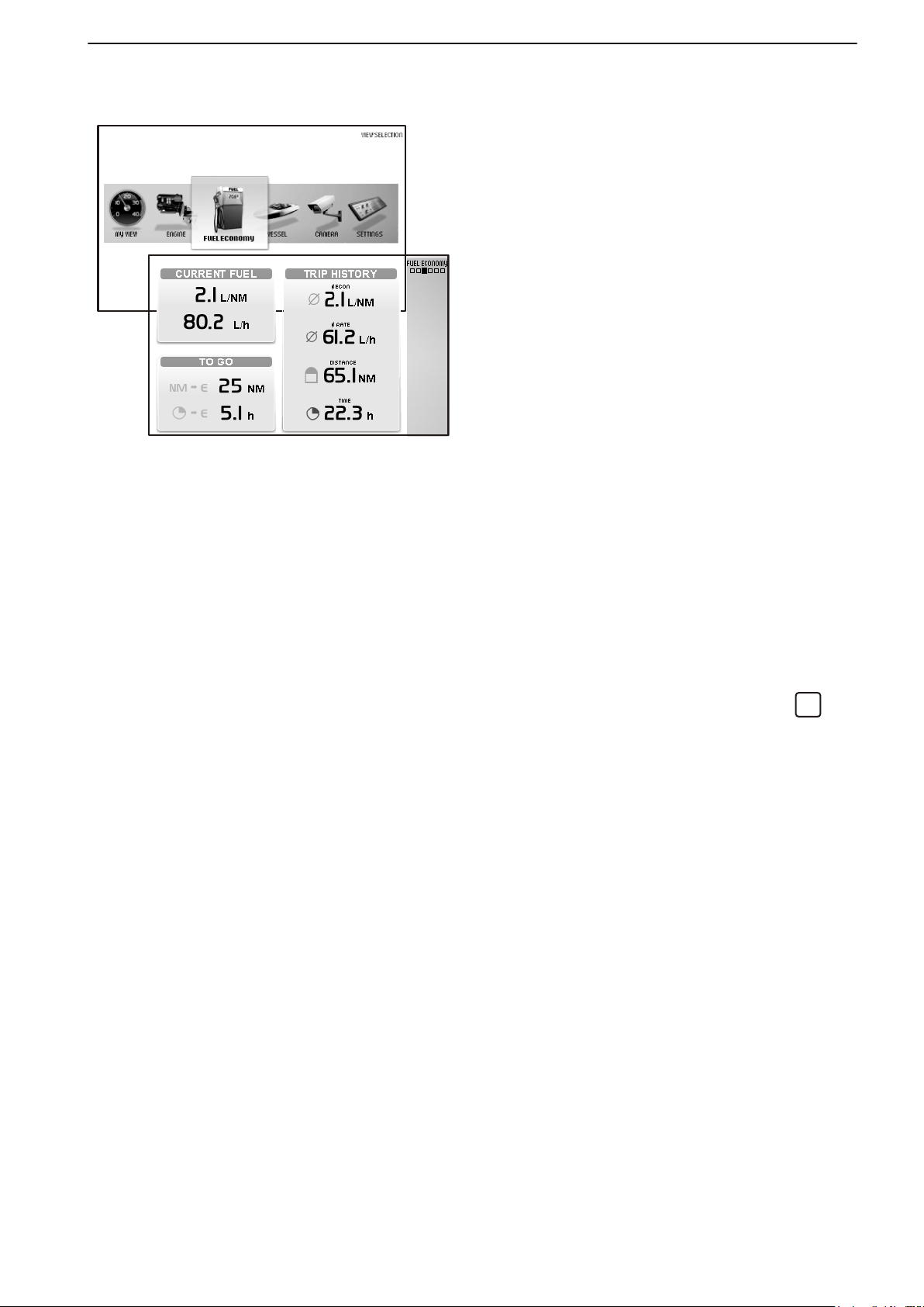
Fuel economy
This view functions as the boat's trip computer.
Depending on the functions installed in the boat, the
following can be displayed:
Current Fuel
Instant fuel rate, based on current fuel consump-
tion
Instant fuel economy, current fuel consumption
per hour.
To Go
Distance
remaining
, trip distance with fuel remaining in the tank based on current fuel consumption.
Time to empty, operating time with fuel remaining
in the tank based on current fuel consumption.
Trip History
Average fuel rate, average fuel consumption since
the last trip computer zero reset.
Average fuel economy, average since the last trip
computer zero reset.
Trip distance, distance travelled since the last trip
computer zero rest.
Trip Time, time travelled since the last trip computer
zero rest.
To zero all values in the trip computer press
.
The information in this view cannot be changed.
47705796 05-2014 © AB VOLVO PENTA 27
Page 30
P0001175
Instruments and Controls
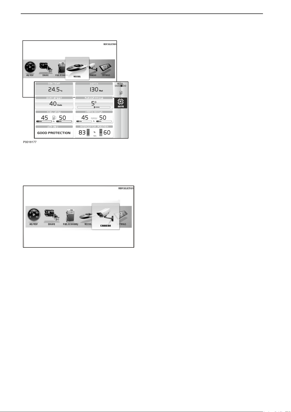
Vessel
Information concerning boat installations is displayed
in this view.
Depending on the functions installed in the boat, the
following can be displayed:
- Sea water temperature
- Depth,to set the echo sounder refer toDepth
Alarm in chapter Settings Menu page 120 .
- Boat Speed
- Rudder angle
- Fuel level
- Freshwater level
- ACP Info
Optional page 53 chapter.
- Interceptor position, for further information refer to
the Volvo Penta Interceptor System chapter.
The information in this view cannot be changed.
,for further ACP information, refer to the
Camera
It is possible to connect a camera to the screen (e.g.
for monitoring the engine compartment or swimming
platform).
If a camera is installed, images will be displayed in this
view.
28 47705796 05-2014 © AB VOLVO PENTA
Page 31

OK
OK
P0001098
P0001043
Instruments and Controls
Settings
Screen settings and different function settings are
made in
Mode
Choose between
background) or Night (light text on a dark background).
Press
Background
Choose between the background colors Gray, Aqua,
White, Carbon and Red.
this view. Turn to the desired menu and press
to access the sub menus.
the modes Day (dark text on a white
to switch between modes.
EVC Settings
Press OK to access the settings menu.
Settings for
audible alarm settings, alarm limits, language and
units. Information regarding boat installations is also
found here.
Neutral Beepswitching on and off the beeper that
sounds when the control is in the neutral position.
Info Beep Levelsetting the volume of the signal that
confirms when a function has been activated, or deactivated.
Trip Computer Resetzeroes all values in the trip computer.
Service
The drive is fitted with a sensor that monitors oil level
and quality. If the oil level in the drive is low or if there
is water in the oil, the helmsman is alerted by an audible alarm and a message is shown on the display
simultaneously. Every time oil is changed, the waterin-oil sensor must be calibrated; refer to
Service page 121
the display, switching functions on and off,
Camerafor laterally inverting the image shown or
showing the camera at a docking station.
Display Typefor selecting the engines the information
in the display concerns, and the type of installation the
display forms part of.
Infodisplay Contrast for adjusting the contrast on all
displays at the helm station.
Unitssetting units (metric/US/imperial) and unit of distance (km, NM or miles).
Languageselecting the display language.
47705796 05-2014 © AB VOLVO PENTA 29
Page 32

OK
3
4
1
2
5
P0001049
Instruments and Controls
Gauge Rangesetting the instrument's maximum
range.
Boat Speed10 – 100 knots in 10 knot stages.
Engine Speed2500, 3000, 4000, 5000, 6000 rpm.
Propeller speed1000, 2000, 3000 rpm.
EVC Informationthis information cannot be changed.
Featuresinstalled functions are marked blue.
Componentspress OK to see installed compo-
nents..
Softwareinformation regarding the software ID
number.
Calibration
The following is only displayed if the function is installed. For further information refer to the appropriate
section in the Settings Menu page 120
chapter.
Speed Correctionsetting the speed factor.
Depthsetting the echo sounder depth alarm. Follow
the instructions on the screen.
Fuel Tankfuel tank calibration. Follow the instructions
on the screen.
ACP Infosetting the ACP protection position.
PTAPTA calibration. Follow the instructions on the
screen.
Warning Manager
If the system discovers a fault, the helmsman is alerted
by a message on the display. The fault message must
be acknowledged by pressing
.
All faults are stored in Warning Manager.
The fault message indicates the driveline affected,
describes the fault and suggests suitable actions.
For further information on fault messages, refer to
Fault Handling page 67.
1 Symbol
2 Shows which driveline the fault was detected in.
3
List of registered faults; turn the knob to browse.
4 Fault message with description and suggestion for action.
5 Service information.
30 47705796 05-2014 © AB VOLVO PENTA
Page 33

OK
!
!
!
!
PT
SB
1
2
3
4
P 1993700
PT
N N
SB
STEERING GEAR
RUDDER ANGLE
OVERLOAD
ACTUATOR
BRAKE
POWER
COMMUNICATION
STEERING GEAR STATUS
DIRECTION OF THRUST
AUTOPILOT ACTIVE
0 0
1
2
3
P 1994600
Instruments and Controls
Alarm display
The alarm display shows a summary of current and
historical engine and transmission alerts.
1 Summary of registered engine and transmission
alerts.
Use the knob to browse between alerts.
Fault message with description and suggestion for
2
action.
3 Service information.
4 Engine status; the color of the lamp next to the
engine symbol shows engine status.
Gray lamp; engine stopped
Green lamp; engine running
Orange lamp; minor malfunction
Red lamp; major malfunction
If the system discovers a fault, the helmsman is alerted
by a message on the display. The fault message must
be acknowledged by pressing
For further information on fault messages, refer to
Fault Handling page 67.
Steering gear display
The rudder angle view is a monitor that shows drive
angle (1
- Direction of thrust
- Overload
- Actuator
- Brake
- Power
- Communication
- Steering gear status
The color of the lamp (2) shows the status of each
drive.
Gray lamp; drive stopped
Green lamp; status OK.
Orange lamp; drive malfunction, steering unaffected
Red lamp; steering affected
Autopilot (3) is shown when the autopilot is running.
) plus status and alerts for:
47705796 05-2014 © AB VOLVO PENTA 31
Page 34

Instruments and Controls
Controls
This section describes the controls Volvo Penta sells
for your engine. Contact your dealer if your boat is
equipped with controls other than those described
here, and you feel uncertain about their function.
Triple installation
Both the
function are controlled using the control levers. The
two control levers controls all engines and propulsion
units.
A If the control levers are in different positions the
B If one of the control levers is in neutral propulsion
C Are the control levers in different positions, one
adjustment of engine speed and the gear shift
centre engine (2) will operate in this range of revolutions.
the centre propulsion unit (2) is also in neutral.
engaged for forward motion and the other for reward
motion, the centre propulsion unit will be in neutral.
Quadruple Installation
Both the adjustment of engine speed and the gear
shift function are controlled using the control levers.
The port side control lever (A) controls the port side
engines and propulsion units 1 and 2. The starboard
control lever (B) controls the starboard engines and
propulsion units 3 and 4.
32 47705796 05-2014 © AB VOLVO PENTA
Page 35

R
F
N
T
T
P0012501
Instruments and Controls
N = Neutral position. Reverse gear/drive disengage-
dand engine at idle.
F = Reverse gear/drive engaged for forward motion.
R = Reverse gear/drive engaged for rearward
motion.
T = Engine rpm control (throttle).
Engine and drive features are controlled with push buttons on the control. What buttons and functions available is depending on the installation.
1 STATION
The
button lamp is lit if the helm station is active and
lit. Refer to Operation page 61 for further information.
2 CRUISE CONTROL
Switch on cruise control by pressing the button.
Fine tune the locked engine speed by increasing (+)
or reducing (-) engine rpm with the button on the
back of the control.
3 LOW SPEED
Refer to Optional page 36 for information.
4 THROTTLE ONLY
Disconnects the shift function so that the control
lever only affects engine speed; refer to "Disengaging shift function" in this chapter for further information.
5 SINGLE LEVER
Switch on the single-lever function by pressing the
button. The lever that is moved from its position first
becomes the control lever for both engines. The
other control lever has no function as long as the
single-lever function is activated. The button lamp
lights up to show that the function is active. Exit the
single-lever function by pressing the button again.
Read more about the single-lever function in
Optional page 37.
6
Neutral position. The symbol shows that the drive/
reverse gear is disengaged.
7
47705796 05-2014 © AB VOLVO PENTA 33
The warning triangle lights up if the system discovers a fault; refer to Fault Handling page 67 for
information.
The
warning triangle lights up on the same side as
the driveline with the indicated fault. In triple installations, both triangles light up if the center driveline
registers a fault.
8 This function is not available.
Page 36

Instruments and Controls
Disengaging the Shift Function
The gearshift function can be disconnected so that the
control lever only operates the throttle.
1 Put the control levers in neutral.
2 Press the control “Throttle Only” button or the
neutral button (N) on the helm station panel.
3 Release the button. The N symbol on the control
will light up as confirmation that the gearshift
function is disengaged and that the lever will
only affect engine revolutions.
To exit neutral mode, press the button again.
Adjusting the friction brake
The control lever has a friction brake that can be
adjusted for lighter or stiffer lever movement. Resistance in click mode can also be adjusted.
1
Switch off the engine.
Remove the cover (3).
2
3 Adjust the friction brake (1) and/or click mode (2)
by turning the screw clockwise for stiffer lever
movement, and counterclockwise for lighter
lever movement.
4 Replace the cover.
34 47705796 05-2014 © AB VOLVO PENTA
Page 37

1
2
3
4
P0016686
Instruments and Controls
Joystick
The joystick is optional. The features are controlled
with push buttons on the control. What buttons and
functions available is depending on the installation.
1 Docking
operation and further function information, refer
For
to Joystick for docking page 39.
2 Dynamic Positioning System
For operation and further function information, refer
to Optional page 49.
3 Joystick Driving
For operation and further function information, refer
to Joystick Driving page 42.
4 High Mode
For operation and further function information, refer
to Joystick for docking page 39.
47705796 05-2014 © AB VOLVO PENTA 35
Page 38

Optional
P0012978
B
B
R
F
N
A
A
P0012499
Low speed
The Volvo Penta low speed function is available for
engines with hydraulic transmissions.
Boats with powerful engines can have high speeds
even at low revolutions; the low speed function
reduces speed.
N = Neutral position.
Transmission is disengaged and engine revolutions are at idle.
F = Forward at idle.
The transmission is engaged for operations
ahead and the engine is at idle; this involves
maximum trolling in the transmission.
R = Reverse at idle.
The transmission is engaged for operations
astern and the engine is at idle; this involves
maximum trolling in the transmission.
A = Low speed engaged.
The transmission affects propeller revolutions.
The engine is not affected.
B = Low speed disengaged.
The control affects engine speed and propeller
revolutions.
Engaging the low speed function
1 Move the lever to the neutral position.
2
Press the Low Speed button on the control or
on the helm station panel to activate the
low speed function.
An audible signal and the message “Lowspeed
activated” (A) will be displayed on screen to
confirm that the function is on.
is shown on the screen if the low speed function
is active (B).
When the
occur when shifting.
Disengage the low speed function
1
2
low speed function is engaged a delay may
Move the lever to the neutral position.
Press the Low Speed button on the control or
on the helm station panel to disengage the
low speed function.
Two audible signals confirm that the function is
switched off and the “Lowspeed deactivated”
(C)message is displayed on the screen.
36 47705796 05-2014 © AB VOLVO PENTA
Page 39

Sport Fishing Mode
P0001219
P0002114
Optional
The Volvo
deep-sea fishing. When the function is activated, the
IPS units are angled outwards and the helmsman can
quickly rotate and maneuver forward/backwards to follow the movement of the fish. When activated, the
wheel is disconnected and the boat is maneuvered
solely via the control levers.
When the function is activated, the wheel is disconnected and the boat is steered with the control levers.
Penta sport fish function was developed for
WARNING!
There is a risk that the boat may take in water if the
movements are too violent.
The single-lever function used together with the sport
fish function makes it possible to control both engines
using just one of the control levers.
Sport fishing
Switching on the sport fishing function
1 Move both control levers to neutral.
2
Press the sport fishing button on the panel.
An audible signal and the message “Sport fishing
activated” will
to confirm that the function is activated.
If it is not possible to switch on the function, check that
the controls are in neutral.
Switching off the sport fishing function
When the function is switched off, both IPS units are
set to dead ahead.
IMPORTANT!
If the controls are at full throttle when the function is
switched off the boat will accelerate forward.
1 Exit the function by pressing the sport fish button
on the panel. An audible signal and the message
“Sport fish deactivated” will be displayed on screen
to confirm that the function is on.
2 It is also possible to exit the function by turning the
wheel more than 30 degrees.
be displayed on screen for 5 seconds
47705796 05-2014 © AB VOLVO PENTA 37
Page 40

P0002114
Optional
Single lever
Switching on the single-lever function
1 In
control levers in neutral.
2
Press the
function.
An audible signal and the message “Single lever
activated” will be displayed on screen to confirm
that the function is on.
3
When the single-lever function is activated, the
lever that is moved from its position first becomes
the control lever for both engines.
The other control lever has no function as long as
the single-lever function is activated.
Switching off the single-lever function
1 Move the levers to neutral.
2 Press the single lever button. A double audible sig-
nal and the message “Single lever deactivated” will
be displayed on screen to confirm that the function
is off.
to activate the single-lever function, put the
order
button to switch on the single-lever
Clear Wake Exhaust System
When running at idle it is possible to select exhaust
discharge above the waterline, which provides
improved comfort, lower noise and reduced vibrations
in the boat.
1
Press the
off.
button to switch the function on and
38 47705796 05-2014 © AB VOLVO PENTA
Page 41

Optional
Joystick
Joystick for docking
Volvo Penta Joystick is a control used for docking and
maneuvering. Practise using the joystick and its functions in a safe and proper manner. Practise how to
operate the boat with both joystick docking and steering functions.
CAUTION!
The joystick maneuvering works differently
depending on if the docking function or steering
function is active.
Practise using
all conditions.
The docking function is designed to be used when
docking or maneuvering in close quarters. Use the
steering wheel and throttle control levers in all other
situations.
The boat is maneuvered by moving the joystick forward, aft, abeam, twisting the top of the joystick and
combinations of the movements.
all means of steering and throttle under
47705796 05-2014 © AB VOLVO PENTA 39
Page 42

Optional
CAUTION!
The boat
even when the joystick has been released.
To slow the boat or reverse its direction, move the joystick in the opposite direction. In order to achieve a
diagonal movement, move the joystick diagonally and
use the joystick knob to adjust the boat’s direction
accordingly.
will continue to move in the selected direction
When the docking function is activated, engine revolutions are limited and the boat can only be steered by
the joystick.
In order to activate the docking function, the following
must be fulfilled:
engines running
•
control levers in neutral
•
helm station active
•
joystick in center position
•
Activating the docking function
Activate docking mode by depressing the docking button (A) on the joystick.
An audible signal will confirm that docking mode is
activated and the docking button lamp will light up.
Exiting the docking function
To exit the function, press the joystick docking button
(A). An audible signal will sound twice to confirm that
docking mode is deactivated, and the docking light will
go out.
The docking function is also deactivated if the controls
are moved from the neutral position.
40 47705796 05-2014 © AB VOLVO PENTA
Page 43

Optional
High Mode
If extra power, e.g. when there is a strong wind or
strong current, the High Mode function may be
engaged.
Activate High Mode
1 Activate the joy stick by depressing the docking
button (
stick is activated and the docking button lights up.
2 Activate the High Mode function by depressing but-
ton (B) on the joy stick.
3 An audible signal confirms that the function is acti-
vated and the high Mode button lights up.
Disengage High Model
Disengage the function by pressing the button again.
An audible signal will sound twice to confirm that docking mode is deactivated, and the light will go out.
The system is now in normal docking mode.
A). An audible signal confirms that the joy
47705796 05-2014 © AB VOLVO PENTA 41
Page 44

P0016372
P0004011
Optional
Joystick Driving
NOTICE! Joystick steering only works together with
Volvo Penta autopilot.
The joystick steering function allows the joystick to be
used during
maneuver the boat in the same way as with the autoplilot and helm steering unit.
Throttle and gear shift controls work in the normal
manner.
Learn to maneuver the boat with the joystick in calm,
open waters.
Joystick steering is activated and de-activated by
pressing the
passage to adjust the boat's heading and
button on the joystick.
When joystick
steering is activated the autopilot is also
started. While the boat is under joystick control the
autopilot is in standby mode; when the joystick is
released to its central position the autopilot is activated
and locks in on the new heading after a few seconds.
Like the autopilot, the helm steering unit is locked when
joystick steering is active but it may always be used for
e.g. changing course or giving way for an obstacle.
Twist the top of the joystick or move it sideways to
reengage joystick steering.
If the autopilot is put in standby mode manually by
means of the STBY button, joystick steering is
switched off and must be reengaged using the button
on the joystick.
Heading adjustments
Twist the top of the joystick to change heading incrementally. A short twist changes the heading by a fixed
increment while a twist held firm will change the heading through several increments.
The autopilot shows the heading with a digital value
and a indicator in shape of a blue triangle, a yellow
arrow shows the new heading that the boat will be set
to.
Maneuvering
The joystick can also be used to maneuver the boat in
the same manner as with a helm steering unit. Move
the joystick sideways to steer the boat in the same
direction. When the joystick is released the autopilot
will set a new heading that corresponds to boat heading.
NOTICE! Full joystick movement to one side corresponds to full helm.
Maneuvering abeam provides a faster response than
adjusting the heading by twisting the top of the joystick.
42 47705796 05-2014 © AB VOLVO PENTA
Page 45

P 1994500
P0004011
P0016372
Optional
Joystick steering, type approved installation
The joystick steering function allows the joystick to be
used during passage to adjust the boat's course and
maneuver
boat in the same way as with the steer-
the
ing wheel. Throttle and gear shift controls work in the
normal manner.
Learn to maneuver the boat with the joystick in calm,
open waters.
Joystick steering is activated and de-activated by
pressing the
button on the joystick.
The steering wheel can also be used when joystick
steering is active e.g. to change course or avoid an
obstacle. Twist the top of the joystick or move it sideways to re-activate joystick steering.
Maneuvering
Twist the top of the joystick to change rudder angle
gradually. A short twist changes the rudder one
degree while a twist held firm will change course
through several degrees.
The joystick can also be used to steer the boat in the
same way as a steering wheel. Move the joystick
sideways to steer the boat in the same direction.
When the
joystick is released the rudder angle reverts
to 0°.
Full joystick movement to one side corresponds to full
helm.
Maneuvering abeam provides a faster response than
adjusting the course by twisting the top of the joystick.
47705796 05-2014 © AB VOLVO PENTA 43
Page 46

STBY
P0016636
Optional
Autopilot
Volvo Penta Autopilot consists of a compass unit and
a 4" control panel. The autopilot constantly adjusts
boat steering to hold the boat on a straight course.
Several different
the autopilot also permits manual steering.
Read the instructions carefully and learn to maneuver
the boat with the aid of the autopilot in calm, open
waters.
The helmsman is responsible for piloting the boat in a
safe, reliable manner. Avoid navigational hazards and
never leave the helm unattended. Always be prepared
to quickly take over the helm.
The autopilot is automatically stand-by mode when the
boat's electrical systems are switched on. The display
will show the main menu or the last menu used.
steering patterns can be entered and
When the autopilot is active the helm steering unit is
locked but may always be used for e.g. changing
course or giving way to obstacles. The autopilot will
then default to stand-by mode and must be activated
again.
If the Shadow Drive function is activated in the Set-
tings menu the autopilot is re-activated automatically
after a course change has been made manually (with
steering wheel). The autopilot is activated on the new
course once the boat has held this course steady for a
few seconds. When Shadow Drive is activated a symbol is shown in the top right corner of the display.
Menus and settings are controlled by the control panel
buttons.
– Return to the previous menu. If the button is
held down
display.
the display will go to the Autopilot menu.
– Menu button functions are shown on the
– Sets the autopilot in standby mode.
44 47705796 05-2014 © AB VOLVO PENTA
Page 47

Main menu
<<10° <1°
1°> 10°>>
STBY
P0015539
STBY
P0015351
Autopilot
•
Optional
•
GPS
Steering,
a waypoint must be marked in a plot-
ter before this menu can be opened.
Pattern Steering
•
Settings
•
Autopilot
Active or stand-by autopilot status is shown in the top
the screen. A green arrow in the top right corner
part of
of the screen confirms activation; if the autopilot is put
in stand-by mode the arrow turns red and flashes for
five seconds.
The set course is shown on the display digitally and by
means of a course indicator in the form of a blue triangle.
ENGAGE — Activates the autopilot.
MENU — Goes to the main menu.
ROUTE — Activates the autopilot to follow a route
on the plotter. This alternative is only shown if a GPS
is connected and a route or waypoint has been created in the plotter. The display shows the distance
to the next waypoint along the plotted route. Refer
to GPS Steering for further information and settings.
Setting a course
The boat's course is set by means of the arrow buttons,
. One click on the button changes the
course 1° at a time; if the button is held down longer
the course is changed in larger steps. A yellow arrow
shows the
new course the boat will be set on. Step size
can be adjusted under the Settings > Navigation set-
tings> Step size menu.
NOTICE! The course shown in the autopilot may deviate from the course shown in a GPS/plotter. This is
because the autopilot shows boat heading, i.e. it does
not take leeway or drift into consideration. On the other
hand, the plotter shows the boats actual track.
47705796 05-2014 © AB VOLVO PENTA 45
Page 48

STBY
P0015810
STBY
P0015808
Optional
GPS Steering
A plotter must be connected for GPS steering to be
selected. A
route with one or more waypoints can then
be created in the plotter to be followed by the autopilot.
Different steering patterns can also be set based on a
marked waypoint.
Route to
1 Create a route using one or more waypoints in the
boat's plotter; refer to the plotter manual for settings.
Select Route to to get the autopilot to begin follow-
2
ing the set route. The distance to the next waypoint
is shown in the autopilot display. If the autopilot is
in stand-by mode, press ROUTE to get the autopilot
to revert to the route.
CAUTION!
Maintain attention
final waypoints.
to boat operation when approaching
Depending on the chartplotter model connected to the
autopilot and the settings input on the chartplotter, the
boat may make unanticipated maneuvers when
approaching the final waypoint in a series of waypoints.
GPS Pattern
Before a pattern is activated in the autopilot a waypoint
must be activated in the plotter; this point will be the
pattern's central marker. The selected pattern, helm
and any other settings are shown on the display.
Pattern steering is deactivated if the boat's course is
changed using the helm or autopilot buttons; reactivation is manual.
Orbit – The boat is steered on a circular course
around the active waypoint. The radius of the circle is
determined by the distance to the waypoint when the
pattern is activated. Setting orbit helm, port or starboard.
Cloverleaf – The boat is steered to the active
waypoint and
then follows a cloverleaf pattern with the
waypoint as the central marker. Setting pattern helm,
port or starboard. The size of the cloverleaf pattern
(from waypoint to outer turn points) can be set under
Settings > Cloverleaf, length; the default setting is 300
m (1000 ft).
Search – The boat is steered to the active way-
point and then follows a spiral pattern with ever greater
circles. Setting pattern helm, port or starboard. Spiral
distance can be set under Settings > Search area; the
default setting is 20 m (50 ft).
46 47705796 05-2014 © AB VOLVO PENTA
Page 49

STBY
P0015809
P0016494
Optional
Pattern Steering
The autopilot can be set to follow a fixed pattern even
when no GPS unit is connected. The set pattern and
its settings are shown on the display.
Pattern steering is deactivated if the boat's course is
changed using
the helm or autopilot buttons; reactiva-
tion is manual.
Zigzag – The boat is steered in a zigzag pattern
along the set course. Setting the angle and times the
pattern must follow.
Circles –
based on its position when the pattern is activated.
Setting
the helm, port or starboard, and the time taken
to complete a circle.
The boat is steered in a circular pattern
Circular pattern
180° turn – The boat turns through 180° and then
maintains the new course. Setting the helm, port or
starboard, for the direction of the turn.
Man over board (MOB) – Turns the boat to come
parallel with the position when MOB was activated.
Speed must be below plane speed for this pattern to
be activated. Setting the helm, port or starboard, for
the direction of the turn.
47705796 05-2014 © AB VOLVO PENTA 47
Page 50

STBY
P0015793
STBY
P0015823
Optional
Settings
Day/night mode
Setting Day mode (light background) or Night mode
(dark background).
Shadow Drive
Switch function on/offShadow Drive. When Shadow
Drive is activated a symbol is shown in the top right
corner of the display.
function is active the autopilot is put in stand-
the
When
by mode when boat steering is taken over manually,
but does not need to be reactivated manually. Once
the boat has held a fixed course for a few seconds the
autopilot is reactivated automatically.
tings menu the autopilot is not automatically reactivated again after the course is adjusted manually (with
steering wheel) and the autopilot has assumed standby mode. The autopilot must be manually reactivated.
Step size
Setting the number of degrees a course is changed
when the Autopilot menu arrow buttons are held down.
Dealer autopilot settings
Settings in this menu may only be changed by an
authorized Volvo Penta dealer.
System
Course
Setting a reference for calculating course information.
Magnetic – calculating a course based on magnetic
North
True – calculating a course based on true North
Declination
Setting declination based on true North. Declination
is only shown if Course is set to True.
Auto – automatically sets declination.
User – Declination is entered manually.
NOTICE! When Shadow Drive is activated in the set-
Operating position
Setting the display for normal operations or demonstration mode.
Factory reset
Settings will revert to the factory settings and zero
the autopilot calibration.
NMEA 2000 devices
List of connected NMEA 2000 units.
48 47705796 05-2014 © AB VOLVO PENTA
Page 51

Optional
Dynamic Positioning System
Volvo Penta IPS Dynamic Positioning system (DPS)
is a
function that aids holding a selected position and
compass heading by means of a GPS signal. The
function is intended as an aid e.g. while waiting for a
berth or for a bridge to open.
From a legal standpoint, the boat is under way when
the DPS is activated. The operator has the same
responsibility regarding supervision and maneuvering
as when making way through water. The helm station
must remain attended.
It is the operator's responsibility to inform passengers
of the risks and make sure no persons or any other
boat or object that can be affected by the operation of
the DPS function are in the water near the boat. When
DPS is active, precision is affected by wind, waves,
current, and GPS signal strength. Keep away from
swimmers or any other boat or object when DPS is
active. The dynamic positioning system can be
affected by strong electromagnetic signals as created
by radar and radio transmitters. Maintain a safe distance, with a minimum of 2 boat lengths to any object.
Show consideration! When the DPS is active, it gives
rise to noise and heavy propeller wash that may
annoy those around. You are responsible for the wake
from your boat.
WARNING!
Check that nobody is in the water before engaging
DPS. Maintain
boat lengths to any object.
Never use it in, or near, areas where people could be
in the water. Personal injury could result from contact
with propellers.
a safe distance, with a minimum of two
WARNING!
With DPS active, the propellers are spinning to keep
the boat in position, creating a slipstream. Keep away
from people in the water. Personal injury could result
from contact with propellers.
CAUTION!
When DPS is in use, the boat may move
unexpectedly. The operator should inform
passengers of
to hold on to prevent falls.
the possibility of abrupt movement and
47705796 05-2014 © AB VOLVO PENTA 49
Page 52

OK
MY VIEW
WARNI NG
PRESS TO
CUSTOMIZE
NW
NE
SE
SW
W
S
E
N
1 2 3 4 5
P0010264
WARNING:
When DPS in Use Boat is Underway
Maintain proper
LOOKOUT
STAY OUT of
water – spinning
propellers.
Failure to observe warnings may result in
SEVERE INJURY or DEATH.
ACCEPT
HOLD ON to
prevent falls – boat
can move suddenly
READ the
owner’s manual
P0010268
1
2
P0010270
Optional
Overview
The DPS view shows when the DPS function is activated.
you browse to another view, the DPS view will
If
be re-displayed after a brief period of inactivity.
1 Fuel level
2 GPS signal strength
3 Bearing
4 Direction of movement
5 DPS symbol
Activating the DPS
The DPS can only be activated when boat speed is
below 3 knots.
The function remains active for a maximum of 12
hours.
In order to engage the DPS, the warning message
shown when the engine is started must be acknowledged. The message is acknowledged by pressing the
button or the knob on the control panel.
Warning message at start
Activating the DPS at the main helm station
1 Make sure that swimmers and boats or other
objects are more than two boat lengths away.
Move the control levers to neutral.
2
3 Press the DPS button (1). An audible signal con-
firms that the DPS is active and the button light is
lit. The screen shows a brief warning message
before switching to the DPS image.
Activating the DPS at the docking station
1 Make sure that swimmers and boats or other
objects are more than two boat lengths away.
2 Press the DPS button (1). An audible signal con-
firms that the DPS is active and the button light is
lit.
50 47705796 05-2014 © AB VOLVO PENTA
Page 53

OK
FUEL LEVEL
RUDDER ANGLE
POWER THRUST LEVEL
The boat has lost
The boat has lost
its chosen position.
DPS is working to find
the chosen position.
P0010443
Optional
Switching off the DPS
The DPS can be switched off in one of the following
ways:
Moving
•
Pressing the DPS button (1).
•
Activating the joystick with button (2).
•
control levers out of the neutral position.
the
Two audible signals confirm that the DPS function is
switched off and the DPS button (1) light goes out.
DPS messages
Messages when active
Should a disturbance occur, the operator is warned by
an audible alarm and a message is displayed on the
screen. The message describes what has occurred
and DPS function status.
Acknowledge the message by pressing
panel or the knob on the control panel, the audible
alarm will stop.
Following is
a list of messages resulting from potential
disturbances:
The boat has lost the selected position. The DPS is
•
working to find the selected position.
on the
The boat has lost the selected heading. The DPS is
•
working to find the selected heading.
The DPS function has switched off. The slip function
•
is no longer accessible.
Unreliable GPS signal. The DPS function may be
•
switched off.
47705796 05-2014 © AB VOLVO PENTA 51
Page 54

Optional
Messages when activating
Should a disturbance occur that prevents activating
DPS, a
sage describes why the DPS cannot be activated.
•
•
•
message is displayed on the screen. The mes-
GPS signal too weak. DPS will not be activated.
If the GPS signal is too weak it may help to wait a
moment since the signal might be temporarliy weak.
Alternatively move the boat to a new position.
Bridges, cranes and tall buildings might obscure the
GPS signal and disturb the function.
Check that the antenna has free range.
DPS cannot be activated. Too few drivetrains accessible. Check that all engines are running. Take
action on possible faults.
All engines must be running in order to engage the
DPS. Make sure all engines are running. Make sure
there are no messages that needs to be acknowledged and attended to.
DPS cannot be activated. Control lever(s) not in
neutral. Move lever(s) to neutral and activate the
DPS.
The control lever(s) must be in neutral position in
order to engage the DPS.
DPS cannot be activated. The boat speed is too
•
high. Reduce speed to 3 knots and start the DPS.
DPS cannot be activated. The slip function is no
•
longer accessible. Take action on possible faults.
The slip function needs to be functioning in order to
engage the DPS. If the slip function isn't calibrated
or if a malfunction has occurred it will not be possible
to engage the DPS. Make sure there are no messages that needs to be acknowledged and attended
to.
DPS antenna failure. DPS will not be activated.
•
52 47705796 05-2014 © AB VOLVO PENTA
Page 55

Optional
Active Corrosion Protection
ACP (Active Corrosion Protection) is a system developed to
in salt water and brackish water.
ACP has three levels of protection that can be monitored by the boat's electrical system. Presentation of
protection status on boat displays can be selected in
My view.
When the system is active a small amount of chlorine
gas is given off. If the smell is disturbing the ACP function can be temporarily switched of as desired in the
settings menu; refer to Protection mode settings. The
system may be switched off for a maximum of 4 hours
during which time the IPS unit is protected against corrosion by means of the secondary system; refer to
Protection levels.
The ACP reverts automatically to normal mode after 4
hours; should you wish to leave chlorine-free mode
earlier do so via the settings menu or by switching on
the ignition.
provide optimum IPS unit corrosion protection
When berthed the boat should be connected to shore
power where provided. If shore power is lacking the
ACP uses the boat's batteries. If the batteries begin to
run down, disconnect the ACP and switch to the secondary system.
NOTICE! To avoid false alarms from the system when
running in freshwater environments where corrosion is
not so aggressive the function should be rendered
inactive. The IPS unit is protected by the secondary
system even when ACP is inactive.
Set the ACP to Normal mode if the boat is move to a
more aggressive environment.
47705796 05-2014 © AB VOLVO PENTA 53
Page 56

Optional
Protection levels
A Good
B Limited Protection (Limited Protection) – secondary
C No Protection (No Protection) – risk of corrosion,
D If the ACP is set to inactive the system cannot iden-
Protection
optimally protected by the ACP function. The ACP
adapts automatically to the corrosion environment
the boat is in.
protection. The IPS has full corrosion protection
from the zinc anode installed in the ACP unit on the
transom (secondary protection).
Check that the batteries are being charged by shore
power; alternatively, start the engine so that the
alternator charges the batteries.
When the boat is in saltwater or brackish water, and
if the system remains in this mode for more than 1–
2 weeks after shore power is connected or an adequate battery charge is achieved, a system check
service should be sought.
system alarm.
Seek system check service.
tify ACP status; three lines will be shown on the display. Should this occur when the system is not set
to inactive, seek service for checks. The three lines
are also shown for just under one minute when ignition is switched on before current protection level
can be shown.
(Good Protection) – the IPS unit is
54 47705796 05-2014 © AB VOLVO PENTA
Page 57

Setting protection level
A
B
C
P0012971
Optional
ACP
three levels of protection, which are selected
has
in the settings menu.
A Normal (Normal), means that protection is active
and functioning in the best way for the conditions the
boat is in.
B Chlorine Free (Chlorine Free); the system has
switched over to protection from the zinc anode for
4 hours and no chlorine gas will be given off.
C Inactive (Inactive Only at Haul) – this mode may only
be used when the boat is taken out of the water, is
on land or if it is to be run in freshwater.
Select this mode before the boat is lifted out of the
water to avoid false alarms. In this mode the IPS no
longer monitors corrosion conditions, but the IPS is
protected by the zinc anode.
When ignition is switched on the system is re-started
and goes to Normalmode.
Settings menu
1
Navigate to ACP in the settings menu. Press
to access the submenu.
2
Use the arrows to set the desired protection mode.
Press to confirm the selection.
47705796 05-2014 © AB VOLVO PENTA 55
Page 58

Starting
1
0
P0005851
Make a habit of visually checking the engine, engine bay and transmission before start. This will help you to
discover quickly if anything abnormal has happened, or is about to happen. Also check that instruments and
warning displays show normal values when you have started the engine.
To minimize
atures below +5°C (41°F) are encountered.
WARNING!
Never use start spray or similar agents to start an engine. This may cause an explosion in the inlet manifold.
Danger of personal injury.
cold start smoke we recommend the installation of an engine heater or engine bay heater if temper-
Before Starting
Check the engine and drive units oil level.
•
Check the coolant level.
•
Open the sea cock.
•
Open the fuel cock.
•
Turn the main switches on.
•
IMPORTANT!
disconnect the current with the main switches
Never
when the engine is running. The alternator and electronics could be damaged.
Start the engine bay fan, where fitted, and allow it to
•
run for at least four minutes.
Check there is sufficient fuel for the planned trip.
•
56 47705796 05-2014 © AB VOLVO PENTA
Page 59

Starting
Starting the Engine
Put the reverse gear in neutral
Put the drive in neutral by moving the control lever(s)
to neutral at all stations.
Turn the ignition on
Turn the starter key to position. I to switch the ignition
on.
Check the information display
a
fault is registered it will be shown in the information
If
display, please refer to Fault Handling page 67 for
further information and recommended actions.
47705796 05-2014 © AB VOLVO PENTA 57
Page 60

S
0
I
I
I
I
I
I
P0012497
Starting
Start the engine
If a station is locked the engines can only be started
and stopped from this station.
Start using the ignition switch
Turn the key for each engine to position III. Release
the key and let it spring back to position I as soon as
the engine has started.
repeated
If
turned back to position 0 first.
Starting with the starter button
Press the starter button for each engine. Release the
button as soon as the engine has started.
If you start from a secondary station, the starter key at
the main control station must be in position I.
Overheating protection
If the starter motor is engaged for its maximum activation time (30 seconds), the starter motor circuit is cut
automatically to protect the starter motor from overheating. If possible, leave the starter motor to cool for
at least five minutes before making a new start attempt.
start attempts are needed, the key must be
Read the instruments and warm the engine up
Allow the engines to idle for the first ten seconds.
Check that instruments and warning displays show
normal values.
Check that no messages are displayed and no warning
signs are showing. If a fault is registred, please refer
to section Fault Handling page 67 for further information and recomended actions.
Warm the engine up at low speed and low load, so
normal operating temperature is reached before full
power is used.
IMPORTANT!
Never race the engine when it is cold.
58 47705796 05-2014 © AB VOLVO PENTA
Page 61

Operation
Learn to handle the engine, controls and other equipment in a safe and proper manner before casting off on your
maiden voyage. Remember to avoid sudden and extreme rudder maneuvers and gear shifts. There is a risk for
passengers and crew falling over or falling overboard.
WARNING!
A rotating
Never drive near bathers or in areas where people could be in the water.
propeller can cause serious injury. Check that nobody is in the water before engaging ahead or astern.
Reading the Instruments
Read all instruments and alarm displays directly after
starting, and then regularly during the voyage.
Alarms
Alarms and messages are shown in the information
display, some alarms do also have a sound alarm. Is
there an alarm instrument installed the lamp in question will flash.
1 Read the message.
Acknowledge the alarm by pressing OK.
2
3 Take the indicated actions, see chapter Fault Code
Register page 71.
The fault will be stored as long as the fault remains. It
is possible to read out the fault code at an upcoming
service.
47705796 05-2014 © AB VOLVO PENTA 59
Page 62

Operation
Maneuvering
Shifting between forward and reverse should be done
at idling. Shifting at higher engine speeds can be
uncomfortable for
stress on the transmission or cause the engine to stop.
If you attempt to shift gear at an excessive engine
speed, a safety function cuts in automatically, and
delays shifting until engine speed has fallen to 1500
rpm.
Always do a forwards/reverse operation as
follows:
passengers and cause unnecessary
1 Reduce engine
or less lose way.
speed to idle and let the boat more
WARNING!
Never shift to reverse when the boat is planing.
2 Move the control lever to neutral with a rapid, dis-
tinct movement. Make a brief pause.
3
Then move the control lever to reverse with a rapid,
distinct movement and increase engine speed.
IMPORTANT!
It is important all engines are running during reversing
maneuvers, to avoid the risk of water entry via the
exhaust pipe into the stationary engine.
60 47705796 05-2014 © AB VOLVO PENTA
Page 63

1
2
3
2
3
P0012976
Operation
This section describes the interchange and activation
of helm stations for type-approved and non-typeapproved installations.
Helm Stations
Changing and activating helm stations
Helm station change
Move the control lever(s) to neutral.
1
The neutral lamp (1
the drive is in neutral.
2 Unlock the helm station being vacated, if it is
locked, by pressing (2). The padlock (3) is extinguished.
3 Activate the helm station being occupied by press-
ing (2).
The lamp in the control button will light up when the
helm station is active.
) on the control lights up when
If the helm station is inactive, the lamp will be extinguished.
If the padlock symbol (3) flashes, the helm station cannot be activated. Another helm station is active and
locked, or unlocked with a drive selected (not in neutral).
Locking/unlocking helm stations
If a helm station is locked it is only possible to start and
stop the engine or change helm stations from there.
Lock or unlock an active helm station by depressing
(2).
The padlock symbol (3) lights up when the helm station
is locked.
47705796 05-2014 © AB VOLVO PENTA 61
Page 64

1
2
P0016646
Operation
Station handling, type approved design
There are three different types of helm station a boat
can be steered from.
Local station
The local helm station has superiority over both the
main helm station and remote helm station. The local
helm station is always able to take over control from
another active helm station without unlocking the
active helm station first.
If there is an additional local helm station that is active
it must first be unlocked in order to transfer control to
another local helm station.
Main Station
The main helm station has superiority over the remote
helm station but is subordinate to the local helm station.
In order for the main helm station to take control from
an active local helm station or another main helm station the active helm station must be unlocked first. The
main helm station can take control from a remote helm
station without unlocking the remote helm station.
Remote station
The remote helm station is subordinate to the local
helm station and the main helm station.
The active helm station must first be unlocked in order
to activate the remote helm station.
Changing helm stations
1 Unlock the active helm station by depressing (1
The padlock (2) will go out on all helm stations.
2 Activate the helm station that is to take control by
pressing (1). The green lamp on the control will
begin flashing. It is possible to take over control
while the lamp is flashing.
Should helm station change not take place while
the lamp is flashing the transfer is interrupted and
command reverts to the previously active helm station.
3 When the control on the helm station assuming
control is synchronized with engine speed and
gear, the lamp in the control will burn continuously
to confirm the transfer. The padlock symbol (1)
lights up to show that the helm station is locked.
).
If the helm station is inactive, the lamp will be extin-
62 47705796 05-2014 © AB VOLVO PENTA
guished.
If the padlock symbol (2) is lit, the helm station cannot
be activated. Another helm station is active and locked,
or unlocked with a drive selected (not in neutral).
Page 65

Operation
Cruising Speed
For best fuel economy operations at full must be
avoided. We recommend a cruising speed that is at
least 10% below the maximum engine revolutions at
top speed (full throttle).
Depending on hull type, the choice of propeller, the
load and sea state etc., the maximum revolutions at
top speed may vary, but they should be within the full
throttle range; refer to Engines.
If the engine does not reach its maximum throttle rangeit can depend on a number of factors mentioned in
the Fault Handling page 69
Select a propeller with greater pitch if actual enginerevolutions exceed the full throttle range. Contact your
Volvo Penta dealer for advice.
Triple installation
Since the center propulsion unit is installed in a tunnel
a slight efficiency loss for engine 2 is to be expected at
cruising speed and wide open throttle.
At cruising speed engine 2 will show slightly higher fuel
burn than engine 1 and 3. At wide open throttle engine
2 will run at a slightly lower RPM (-40–80 RPM) than
engine 1 and 3.
sedtion.
47705796 05-2014 © AB VOLVO PENTA 63
Page 66

Engine Shutdown
Allow the engine to run at low idle, in neutral, for a few minutes after operations are completed. In this way afterboiling is avoided at the same time as temperature equalization takes place. This is especially important when
the engine has been run at high rpm or under heavy load.
Stop the Engine
If a station is active and locked the engines can only
be started and stopped from that station.
IMPORTANT!
Never disconnect the current with the main switches
when the engine is running. The alternator and electronics could be damaged.
IMPORTANT!
Make sure the starter key is in 0-position or removed
before main switches are switched off. Otherwise the
alternator and electronics could be damaged.
Stop with key
Disengage the drive by putting the control lever in
1
neutral.
2
Turn the keys to stop position “S”. Keep the key
turned until the engines stops. The key will automatically return to the “0” position when it is
released and can then be removed.
The starter keys must be in the “0” position or
removed before main switches are switched off.
Stopping with the stop button
1 Disengage the drive by putting the control lever in
neutral.
2 Push the stop buttons. Release the buttons when
the engines have stopped.
64 47705796 05-2014 © AB VOLVO PENTA
Page 67

STOP
P0009744
P0010432
Engine Shutdown
Auxiliary stop
If
engine cannot be stopped in a normal procedure,
the
it is possible to stop the engine via auxiliary stop
mounted on the side of the engine.
After Engine Shutdown
Check the engine and engine bay for leakages.
•
Close the fuel taps.
•
Close the sea cock.
•
Take an hour meter reading and carry out preven-
•
tive maintenance according to the maintenance
schedule.
Turn off the main switches before any long stop-
•
page.
47705796 05-2014 © AB VOLVO PENTA 65
Page 68

C
0
10
10
F
32
50
10
20
70
20
20
60
P0005905
Engine Shutdown
Operation Break
Operation break with the boat in water
boat is not used, but left in the water, the engine
If the
must be warmed up at least once every fortnight. This
prevents corrosion damage in the engine.
If you expect the boat to be unused for two months or
more, it must be inhibited, please refer to Storage.
Cold Weather Precautions
If the engine bay cannot be kept frost free, the raw
water system must be drained and the freshwater system coolant must have sufficient frost protection to
prevent frost bursting; refer to Seawater System,
Draining page 98 and Maintenance page 94
respectively for more detailed information.
Check the charge status of the battery. A poorlycharged battery can freeze and burst.
66 47705796 05-2014 © AB VOLVO PENTA
Page 69

Fault Handling
Battery voltage incorrect.
Check voltage level, alternator and
batteries
Acknowledge fault by pressing the
OK button
Contact a Volvo Penta workshop if the
faults remains.
P 1248900
Despite regular maintenance according to the maintenance schedule and perfect operation conditions faults may
occur which must be attended to before the boat can travel further. This chapter describes alarms and fault
handling.
Alarm handling
Message from engine and EVC system
malfunction is discovered the driver is warned by a
a
If
buzzer sounding and a message showing in the display.
The message toggles between cause of fault and tasks
to perform.
Information regarding ”cause of fault” and ”measures
to take” is found in chapter Fault Code Register.
The engine, transmission and EVC system is monitored by the diagnostic function. Should the diagnostic
function discover a malfunction it protects the engine
and ensures continued operation by affecting the
engine. Depending on how serious the malfunction is
the effect on the engine varies.
Minor malfunction which does not damage the
•
engine or transmission
Affect on engine: None.
Serious malfunction which will not immediately dam-
•
age the engine or transmission e.g. high coolant
temperature.
Affect on engine: Engine power is reduced until
faulty value becomes normal.
Serious malfunction which will cause serious dam-
•
age to engine or transmission.
Affect on engine: Engine power is reduced.
Serious malfunction which makes it impossible to
•
control the engine or transmission.
Affect on engine: Transmission is disengaged and
engine speed is reduced.
Serious malfunction on transmission or in the engine
•
fuel injection system.
Affect on engine: Engine is stopped.
47705796 05-2014 © AB VOLVO PENTA 67
Page 70

Fault Handling
Acknowledge message
1 Push OK to ackowledge the alarm. The buzzer
becomes silent.
Read the message.
2
3 Push OK again and the message disappears.
The alarm has to be acknowledged before the engine
can be started.
Faults list
If a fault is registered Faults (Faults) is displayed in the
information panel together with the number of faults.
1 Press OK to get to the submenu.
2 Browse through the fault list using the arrows if
more than one fault is registered.
3 Press OK twice to see information about the cause
of the fault and the remedy.
4
Return to the previous menu by pressing
.
Deleting faults from the list
Acknowledged faults that have been stored are
deleted automatically when the ignition key is turned
the
stop position. Stop the engine and check that the
to
ignition key is in position 0 at all helm stations.
When system power is reconnected, the diagnostic
function checks if there are any faults in the EVC system. If there are the fault message is shown on the
display.
Faults that have been remedied or have disappeared
are automatically deleted. Faults that have not been
remedied must be acknowledged every time system
power is switched on.
68 47705796 05-2014 © AB VOLVO PENTA
Page 71

Fault Handling
Fault Tracing
A number of symptoms and possible causes of engine malfunctions are described in the table below. Always
contact your Volvo Penta dealer if problems occur which you can not solve by yourself.
NOTICE! Read through the safety advice for care and maintenance work in the Safety
before starting work.
Symptoms and possible causes
Pop-ups are shown in the tachometer display See chapter Fault Code Register
Engine can not be stopped 2, 4, 5, 7, 8
Starter motor does not rotate 1, 2, 3, 4, 5, 6, 8, 9, 10, 35, 38
Starter motor rotates slowly 1, 2
Starter motor rotates normally but engine does not start 1, 11, 12, 13, 14, 37, 38
Engine starts but stops again 1, 11, 12, 13, 14, 19, 36, 38
Engine does not reach full operating speed at full throttle 12, 13, 14, 15, 16, 17, 18, 19, 20, 23, 33, 36, 38, 39
Engine runs unevenly 14, 15, 39
Engine vibrates 24
High fuel consumption 15, 16, 18, 21, 36
Black exhaust smoke 19
Blue or white exhaust smoke 21, 34
Lubrication oil pressure too low 22
Coolant temperature too high 25, 26, 27, 28, 29, 30, 31, 32
Coolant temperature too low 31
No charge or poor charge 2, 40
Information page 6 chapter
1. Flat batteries
2. Poor contact/open circuit in cables
3. Main switch turned off
4. One of the semi-automatic circuit breakers in the distribution box has tripped
5. Faulty key switch
6. Control lever not in neutral/control position not activated
7. Faulty stop relay
8. Faulty main relay
9. Faulty starter relay
10. Faulty starter motor/solenoid
11. Lack of fuel:
- fuel taps closed
-
fuel tank empty
- wrong tank connected
12. Blocked fine fuel filter/pre-filters
(caused by contamination or fuel stratification at low temperature)
13. Air in the fuel system
14. Water/contamination in fuel
15. Boat abnormally loaded
16. Fouling on hull/propeller
17. Cables for unit injector damaged (open circuit)
18. Faulty unit injectors (nozzles)
47705796 05-2014 © AB VOLVO PENTA 69
Page 72

Fault Handling
19. Insufficient air supply to engine:
- blocked air filter
-
air leakage between turbocharger and engine inlet manifold
- fouled compressor section in turbocharger
- faulty turbocharger
- poor engine bay ventilation
20. Excessive coolant temperature
21. Too low coolant temperature
22. Too low oil level
23. Faulty / wrong propeller
24. Faulty engine mounting
25. Coolant level too low
26. Air in the freshwater system
27. Faulty circulation pump
28. Closed seawater inlet
29. Blocked seawater inlet/pipe/filter
30. Defective impeller in seawater pump
31. Defective thermostat
32. Blocked heat exchanger insert
33. Blocked aftercooler
34. Too high oil level
35. Water entry into engine
36. High back pressure in exhaust system
37. Faulty engine speed sensor
38. Stored fault codes
39. Non-return valve in feed pump leaks
40. Alternator drive belt slips/broken
70 47705796 05-2014 © AB VOLVO PENTA
Page 73

Fault Code Register
1
2
3
4
5
6
7
P0004761
CAUTION!
Read the
When a malfunction is discovered the helmsman is warned by a sound alarm and at the same time a message
is shown in the display.
This chapter gives a more detailed description of the messages together with suggested actions to take.
safety precautions for maintenance and service in the Safety Information chapter before starting work.
Message
If a malfunction is discovered a message is shown on
the display.
together with a description of how the system might be
affected and suggested actions to take.
The message is presented in the list below
Alarm Display (optional)
If a lamp in the alarm monitor flashes a malfunction is
detected.
1 Is the orange “water in fuel” lamp lit there is to much
water in the water separator on the fuel pre-filter.
2 Is the charging lamp lit the alternator has stopped
charging.
3 Is the coolant temperature lamp lit the coolant tem-
perature is to high.
4 Is the orange coolant level lamp lit during operation
the coolant level is to low.
5 Is the orange oil level lamp lit during operation the
engine oil level is to low.
6 Is the red warning lamp lit during operation a seri-
ous malfunction has been discovered.
Is the orange warning lamp lit during operation a
malfunction has been discovered.
7 Is the red oil pressure lamp lit during operation the
engine oil pressure is to low.
47705796 05-2014 © AB VOLVO PENTA 71
Page 74

Fault Code Register
Emergency Stop Switch
Reset auxiliary stop button.
Battery Voltage
Check belt tension. Refer to Drive Belt, Check and Change page 86
Check battery fluid level. Refer to Battery, Maintenance page 105.
.
Check Corrosion Status
The active corrosion protection (ACP) status is unknown. Corrosion protection not guaranteed. Refer to Optional page 53.
The active corrosion protection (ACP) is not available. Check that the batteries are charged by land current or by the alternator.
Check Control Lever
Shift and throttle incorrect.
Slip function not available.
Acknowledge fault by moving control to neutral and press OK-button.
Engine power is reduced. Gear automatically set to neutral.
Check Engine
Miscellaneous system faults. Engine performance might be affected.
Some possible explanations to the disturbance listed.
• Battery voltage incorrect.
Check belt tension. Refer to Drive Belt, Check and
Change page 86
Check battery fluid level. Refer to Battery, Maintenance page 105.
• Fuel pressure incorrect. Engine performance might be affected.
• Communication failure. Gear automatically set to neutral. Engine performance might be affected.
• Oil pressure too low.
Engine power is reduced. Checking Engine Oil Level. Refer to Oil level,
checking and topping up page 87.
Check that no leakage occurs.
Please contact a Volvo Penta workshop if the fault remains.
.
Check EVC System
Internal fault in EVC system. Engine performance might be affected.
Some possible explanations to the disturbance listed.
• Limited or no steering. Please contact a Volvo Penta workshop.
• Shift and throttle unavailale. Gear automatically set to neutral. Engine
power is reduced. Helm station has lost communication with engine.
Use alternative helm station if possible.
• Control panel failure. Check if any button has stuck.
Please contact a Volvo Penta workshop if the fault remains.
Check Joystick(Check Joystick)
Joystick failure. Check if any button has stuck.
Joystick not available or limited function. Use steering wheel or choose alternative station.
Check Multilink
Limited instrumentation. Control unit has communication fault.
72 47705796 05-2014 © AB VOLVO PENTA
Page 75

Check transmission
Gear automatically set to neutral. Gear shift not available until fault acknowledged. Acknowledge
Gear shift malfunction. Engine is emergency stopped.
Gear shift malfunction.
Limited slip function.
Low speed not available.
Transmission oil pressure not available.
Transmission oil temperature not available.
Check the transmission oil level and that the oil does not show signs of water
emulsion. Refer to Transmission lubricant, checking and topping
up page 109.
Please contact a Volvo Penta workshop if the fault remains.
fault by moving control to neutral and press OK-button.
Check Control Lever
Gear shift unavailable.
Acknowledge fault by moving control to neutral and press OK-button.
Check Steering Wheel(Check Steering Wheel)
Limited or no steering.
Please contact a Volvo Penta workshop.
Fault Code Register
Coolant Level
Low coolant level. Check coolant level. Refer to Maintenance page 95
Check for coolant leakage.
.
Coolant Temperature
Coolant temperature too high.
Engine power is reduced.
Check coolant level. Refer to Maintenance page 95
Check that the seawater filter is not blocked. Refer to Seawater Filter, Check
and Cleaning page 101.
Check the impeller in the seawater pump. Refer to Impeller, Check and
Change page 100.
Check that no leakage occurs.
.
Engine Oil Level
Oil level too low.
NOTICE! In rough following seas or head seas, the system can incorrectly
sense that the engine oil level is too low. If this happens, acknowledge the
fault, and check the points below for safety reasons.
Check the oil level in the engine. Refer to Oil level, checking and topping
up page 87.
Check that no leakage occurs.
Engine Oil Pressure
Oil pressure too low.
Engine power is reduced.
Check the oil level in the engine. Refer to Oil level, checking and topping
up page 87
Check that no leakage occurs.
.
Engine Oil Temperature
Engine oil temperature too high.
Engine power is reduced.
Check the oil level. Refer to Oil level, checking and topping up page 87
Check that no leakage occurs.
47705796 05-2014 © AB VOLVO PENTA 73
.
Page 76

Fault Code Register
Engine Speed
Engine performance might be affected.
Engine power is reduced.
Please contact a Volvo Penta workshop.
Fuel pressure
Fuel pressure too low.
Check fuel level.
Check that
to Maintenance page 90.
Check for fuel leakage.
the fuel filters are not blocked. Replace filters if necessary. Refer
Helm Restarted
The engine has lost communication with a helm station.
Engine power is reduced.
Key Failure
A button on the e-Key panel depressed. Verify the button.
Primary Battery
Poor batteries or charging. Refer to Battery, Charging page 106
.
Sensor failure
Engine performance might be affected.
Please contact a Volvo Penta workshop if the fault remains.
Steering failure
Limited functionality.
Self test
cant, checking and topping up page 109.
failed. Verify hydraulic steering oil level. Refer to Transmission lubri-
Steering failure
Engine power is reduced. Limited steering
The helm station has lost communication with the steering actuator.
Please contact a Volvo Penta workshop.
Transmission Oil Pressure
Reverse gear oil pressure too low.
Check the oil level. Refer to Oil level, checking and topping up.
Check that the oil strainer is not blocked. Refer to Oil Strainer, Cleaning.
Water in Fuel
Empty the water trap underneath the fuel filters. Refer to
Maintenance page 90
.
74 47705796 05-2014 © AB VOLVO PENTA
Page 77

In Case of Emergency
Despite regular maintenance according to the maintenance schedule and perfect operation, faults may occur
which must
possible faults.
There are safety functions which are activated when certain faults occur, to protect the engine. The following can
occur:
• Engine can not be started.
• Gear in neutral and engine speed is limited to 1500 rpm, no steering.
• The engine stops.
If fault occurs, acknowlege any alarm and take the recommended measures. Please refer to this chapter and
Alarm handling page 67.
be attended to before the boat can travel further. This chapter contains tips for rectifying some of the
If one or two engine(s) stops working, or operates at
reduced engine speed, it is recommended to avoid
operating at wide open throttle or high speeds for longer periods. The engine load for the engine(s) that is
(are) still working will be much higher than it normally
should be when all engines are working and this could
cause excessive wear to the engine(s) and propulsion
unit(s).
Triple installation
A boat with a triple installation is not likely to experience a serious fault on all engines and propulsion units
simultaneously. If a serious fault occurs which prevents one or two engine(s) and propulsion unit(s) from
working normally it will still be possible to operate the
boat to your destination using the control levers and
the steering wheel.
If the engines and propulsion units on each side (1 &
3) are working it is also possible to operate the boat
with the joystick.
Running Aground
If the boat has been run aground or into an object in a
way that may have damaged any of the propulsion
units or propellers, the boat must be run (if possible) at
reduced speed or towed to the nearest harbor. Take
the boat out of the water and let an authorized Volvo
Penta workshop inspect the propulsion units and propellers. Undetected damage could lead to serious propulsion unit damage.
47705796 05-2014 © AB VOLVO PENTA 75
Page 78

P0002107
In Case of Emergency
Starting Using Auxiliary Batteries
WARNING!
Explosion hazard. Batteries contain and give off an
explosive gas which is highly flammable and
explosive. A short circuit, open flame or spark could
cause a violent explosion. Ventilate well.
WARNING!
Never confuse
batteries. Risk of arcing and explosion.
1 Check that the auxiliary battery has the same
voltage as the engine system voltage.
2 Connect the red positive cable to the plus (+)
terminal on the discharged battery and then to
the plus terminal on the auxiliary battery.
the positive and negative poles on the
3 Connect the black start cable to the minus (–)
terminal on the auxiliary battery and to a place
a little distance away from the discharged battery, e.g. the start motor's negative terminal.
WARNING!
Under no circumstances may the black jumper
cabel (–)
tion on the starter motor.
4 Start the engine and let it run at fast idle for
come in contact with the positive connec-
approximately 10 minutes to charge the batteries. Make sure there is no extra equipment connected to the electrical system.
WARNING!
Working with or approaching a running engine is a
safety risk. Watch out for rotating components and
hot surfaces.
WARNING!
Do not touch the connections during the start
attempt: Risk of arcing.
Do not bend over any of the batteries either.
5 Turn off the engine. Remove the start cables in
the exact opposite order to their connection.
76 47705796 05-2014 © AB VOLVO PENTA
Page 79

In Case of Emergency
Emergency Steering
Emergency Alignment, Propulsion Unit
If a
fault occurs which prevents one or several propulsion units from being operated with the steering wheel
it is possible to align the propulsion unit(s) for straight
forward operation manually using the description
below.
If one or several propulsion units can be operated by
the steering wheel, this emergency operation is not
necessary. However, it could be that the steering ability
is badly unbalanced if the non working propulsion
unit(s) is locked in a disadvantageous angle, then
alignment of the non working propulsion unit(s) will
improve the steering ability. The operator determines
whether the alignment is necessary or not, in order to
maneuver the boat in a safe way to the nearest harbor.
If steering is out of order on all propulsion units, align
all propulsion units and use control levers to steer the
boat.
The tools needed during this operation are delivered in
a special tool box together with the boat.
WARNING!
Working with or approaching a running engine is a
safety risk.
surfaces.
The following procedure can be carried out with the
engines running, even though it is not recommended.
Wear hearing protection when in the engine room as
there is a risk of harmful sound levels.
Watch out for rotating components and hot
47705796 05-2014 © AB VOLVO PENTA 77
Page 80

STOP
6
5
2
1
1
2
3
3
4
P0012503
In Case of Emergency
1 Unscrew and remove the plug (1). Disconnect the
cable by
time wiggle the connector in “forward” position.
2 Connect the switch (3) and fit the red crank tool (4).
3 Press the switch button (5) down and keep it
pressed while turning the crank tool carefully to an
end position (6). When the end position is reached,
stop turning. The end position feels like a compression spring.
IMPORTANT!
Do not force the crank tool beyond the end position,
it could damage the propulsion unit.
pressing down the lock (2) and at the same
78 47705796 05-2014 © AB VOLVO PENTA
Page 81

10
75
7
8
9
4
5
6
P0012504
In Case of Emergency
4 Turn the crank tool back 75 turns (7). The propul-
sion unit
5 Remove the crank tool. Disconnect the switch (8)
by pressing down the lock and at the same time
unplugg the switch by slowly wiggling it.
Screw back the plug (9).
6 Reconnect the cable (10) you disconnected in step
1.
is now aligned for straight forward motion.
47705796 05-2014 © AB VOLVO PENTA 79
Page 82

In Case of Emergency
Emergency steering with control levers
fault occurs which prevents all propulsion units from
If a
being operated with the steering wheel, align all the
propulsion units and use the steering method described below to reach nearest habor.
If one or several propulsion units can be operated by
the steering wheel, the steering method described
below is not needed.
Rotate the boat
Put one control lever in the position for forward and put
the other control lever in the position for reverse. Use
a suitable engine speed for maneuvring.
The direction of rotation is determined by the lever
which is put in the position for reverse. If the boat is to
move to starboard, the starboard control lever should
be put in the position for reverse.
Steering the boat
Put the control levers in forward. Use a suitable engine
speed for maneuvring.
The direction of the steering is determined by the use
of the control levers. If the boat is to turn to starboard,
reduce speed on starboard engine. The greater the
difference in speed between the control levers the
more the boat turns. To make a sharp turn, move one
of the control lever to reverse for a moment.
80 47705796 05-2014 © AB VOLVO PENTA
Page 83

Maintenance Schedule
Your Volvo Penta engine and its equipment are designed for high reliability and long life. The engines are built to
withstand the
transmission are serviced regularly according to the schedule, these qualities will be retained and unnecessary
malfunctions will be avoided.
Warranty inspection
During the initial period of use a special warranty inspection – a First service inspection – must be carried out by
an authorized Volvo Penta workshop. Instructions regarding how this must be done can be found in the Maintenance Schedule below and in the Warranty and service book.
Volvo Penta reserves the right to adjust service interval and content after the printing of the Operator’s Manual.
The current document can be found at Publication Search/Service Protocol at www.volvopenta.com.
FSI = First Service Inspection C = Clean
S1, S2, S3 = Special Interval Service R = Replace
A - F = Type of service (regular service) A = Adjustment
FSI = First Service Inspection
After the first 50-100 hours
Inspection with VODIA (Diagnostic Tool)
Coolant level and antifreeze mixture I
Drive belts, belt tensioner and idler wheels I
Air Filter I
Fuel pre-filter, draining water / contamination C
Seawater filter C
Start and warm up engine
Engine and transmission, abnormal noises I
Engine and transmission, oil / fuel / water leakage I
marine environment, but also to have the smallest possible environmental impact. If the engine and
L = Lubrication
I = Inspection (includes, if necessary, cleaning, adjust-
ment, lubrication and change)
(1)
(2)
I
1) Or within 180 days of the date of delivery, or the end of the first season, whichever comes first.
2) Readout if any fault codes and LVD
S1
Every 125-500 Hours / at Least Every 12 Months
Engine Oil and Oil Filters / By-pass filter R
1) Oil change intervals vary, depending on oil grade and sulfur content of the fuel.Change the filters during each oil change.
(1)
S2
Oil Analysis
See dealer's information
SB 17–0–2
I
S3
After the first 1000 hours
Valve clearance I
47705796 05-2014 © AB VOLVO PENTA 81
Page 84

Maintenance Schedule
A
Every 500 hours / At least every
(month)
12 24 48
Inspection with VODIA (Diagnostic Tool)
Coolant level and antifreeze mixture I ●
Drive belts, belt tensioner and idler wheels I ●
Batteries, electrolyte level I ●
Air Filter I ●
Fuel pre-filter, draining water / contamination C ●
Seawater filter C ●
Seawater pump, impeller and o-ring I ●
Transmission, oil and filter R ●
Drive unit, function check of exhaust cock I ●
Anode - Transom. (Must not be painted) I ●
Start and warm up engine
Engine and transmission, abnormal noises I ●
Engine and transmission, oil / fuel / water leakage I ●
(1)
I ●
1) Readout if any fault codes and LVD
B
Every 1000 hours / At least every
(month)
12 24 48
Fuel pre-filter, filter insert R ●
Fuel fine filter R ●
Air Filter R ●
Impeller, Seawater Pump R ●
Anodes - Charge air cooler and / or Heat exchanger. (Must not be painted) R ●
Engine and transmission, inspect hoses and cable clamping I ●
Engine and transmission, cleaning / painting I ●
C
Every 1500 hours / At least every
(month)
12 24 48
Propellershaft seal. (Lubrication of shaft splines) R
Anode - Lower Gear. (Must not be painted) R ●
82 47705796 05-2014 © AB VOLVO PENTA
Page 85

Maintenance Schedule
D
Every 2000 hours / At least every
(month)
12 24 48
Valve clearance I
Drive Belt R ●
Turbocharger, inspect / clean as required I ●
E
Every 8000 hours / At least every
(month)
12 24 48
Coolant VCS (yellow)
1) Different types of coolant must not be mixed with each other.
(1)
R ●
47705796 05-2014 © AB VOLVO PENTA 83
Page 86

Maintenance
This chapter contains general technical information and instructions on how the prescribed maintenance items
must be carried out. Read through the instructions carefully before starting work. The times when maintenance
items must be carried are indicated in the Service Protocol.
Read through
work on the engine is begun.
WARNING!
Care and
before opening or removing the engine hatch/hood. Make it impossible to start the engine by removing the start
key and cutting the system voltage with the main switches.
the safety precautions for maintenance and service in the Safety Information page 4 chapter before
maintenance work should be done with the engine stopped unless otherwise specified. Stop the engine
1 Expansion tank
2 Coolant filler cap
Fuel fine filter
3
4 Oil filter
5 By-pass filter for engine oil
6 Auxiliary stop
7 Air filter indicator
8 Air Filter
9 Alternator
10 Relays
11 Oil filler cap, engine (¹)
12
Oil dipstick, engine
13 Heat exchanger
14 Fuel feed pump (hand pump)
15 Seawater Pump
16 Oil filler, IPS
17 Oil drain, IPS
18 Oil dipstick, IPS
19 Exhaust tap, IPS
20 Anode
21 Oil drain, IPS
1 Steering Unit Servo (SUS)
(1)
2 Oilfilter, IPS
Turbo
3
4 Starter motor
5 Charge air cooler
6 Charge air cooler
7 Coolant Pump
1. May also be located on the right side of the engine.
84 47705796 05-2014 © AB VOLVO PENTA
Page 87

Maintenance
Engine, General
General inspection
Make a habit of visually checking the engine and
engine bay before starting, and after operations when
you have
cover abnormalities quickly, or if something is about to
happen.
Look especially carefully for oil, fuel and coolant leakages, loose bolts, worn or poorly-tensioned drive
belts, loose cable connections, damaged electrical
cables and hoses. This inspection only takes a few
minutes and can prevent serious malfunctions and
expensive repairs.
Accumulations of
in the engine room is a fire hazard and must be
removed immediately they are detected.
stopped the engine. This will help you to dis-
WARNING!
fuel, oil and grease on the engine or
WARNING!
oil, fuel or coolant leak is detected, the cause must
If an
be investigated and the fault rectified before the engine
is started.
Never direct the jet from a high-pressure washer at
seals, rubber hoses or electrical components. Never
use the high pressure setting for engine cleaning.
Air Filter, Change
1 If indicator is all red after the engine is stopped,
change the filter insert.
2 Undo the clamps and remove the lid from the filter
housing.
3 Remove the old filter. Be careful to ensure that no
contamination gets into the engine.
4 Install a new air filter and tighten the lid.
5 Reinstate the pressure drop indicator by pressing
in the indicator button.
IMPORTANT!
Scrap the old filter. It must not be cleaned.
47705796 05-2014 © AB VOLVO PENTA 85
Page 88

Maintenance
Drive Belt, Check and Change
WARNING!
Stop the
General
Check belt tension and condition regularly. The drive
belt has an automatic tensioner and need not be
adjusted. Check that the belt tensioner does not bottom.
IMPORTANT!
Always change a belt which looks worn or cracked.
Changing the alternator belt
engine before doing any maintenance work.
the
1 Remove
2 Put a socket wrench in the tensioning roller
square fitting. Turn the tensioning roller aside
and secure it by inserting a screwdriver or similar into the space which opens up.
protective cover over the drive belt.
3 Remove the drive belt.
4 Install the new drive belt and release the locking
of the belt tensioner. Make sure the drive belt fits
properly into the grooves.
5 Fit the protective cover over the drive belt.
86 47705796 05-2014 © AB VOLVO PENTA
Page 89

P0002089
1
2
P0009747
Maintenance
Lubrication System
Oil change intervals can vary depending on oil grade
and sulphur
cal Data page 130.
Oil change intervals must never exceed a period of 12
months.
If you want longer oil change intervals than given in the
table Technical Data page 130, the condition of the oil
must be checked by the oil manufacturers through regular oil testing.
Oil level, checking and topping up
content of the fuel, please refer toTechni-
The oil level must be inside the marked area on the
dipstick (1) and should be checked daily before the first
start.
Top up the oil through the filling hole on the side of the
engine (2). Check that the correct level has been achieved. Wait a few minutes to allow the oil to run down
into the sump.
IMPORTANT!
Do not fill up above the maximum oil level. Only use a
recommended grade of oil, please refer to Technical
Data, Lubrication System.
47705796 05-2014 © AB VOLVO PENTA 87
Page 90

1
P0009748
Maintenance
Engine Oil, Change
Always follow the recommended oil change interval.
manual or electric oil drain pump (optional equip-
Use a
ment.) to pump the oil out of the oil pan.
WARNING!
Hot oil and hot surfaces can cause burns.
WARNING!
Working with or approaching a running engine is a
safety risk.
surfaces.
1 Run the engine until warm so that the oil is easier
to pump. Then stop the engine.
2 Remove the plug (1) from the oil pan and connect
an oil drain pump. Pump out the oil.
3 Replace the oil filter and by-pass filter at every oil
change; refer to the Oil Filter/By-pass Filter,
Change page 89 section.
Watch out for rotating components and hot
4 Fill oil to the correct level vial the filler opening on
the side of the engine; refer to the Technical Data,
Lubrication System section for oil quantity.
IMPORTANT!
Use only oils of the recommended grades; refer to
the Oil Grade and Oil Change Interval section.
5 Start the engine and let it idle. Check that the low
oil pressure warning lamp goes out and that no
leaks are present at the filters.
6 Stop the engine. Wait a few minutes before check-
ing the oil level. Top up as needed.
Hand the old oil in to a re-cycling station.
88 47705796 05-2014 © AB VOLVO PENTA
Page 91

2
1
2
P0010347
Maintenance
Oil Filter/By-pass Filter, Change
The oil
oil change.
Remember to hand the old filters in to a re-cycling station.
filter and bypass filter must be replaced at every
WARNING!
Hot oil and hot surfaces can cause burns.
1 Place a collection vessel underneath the filter drip
tray to avoid oil spillage.
2
Clean the filter bracket.
3 Unscrew the bypass filter (1) and the oil filters (2)
with a suitable puller.
4 Check that the mating surfaces on the filter bracket
are clean and that no remains from the old gaskets
are left.
5 Moisten the gaskets on the new filters with engine
oil.
6 Screw on the filter by hand until the rubber gasket
touches the filter bracket mating surface. Then turn
a further 3/4 to 1 turn.
7 Start the engine, run at low idle, and check that no
leakage occurs. Check the oil level after the engine
has stopped.
47705796 05-2014 © AB VOLVO PENTA 89
Page 92

Maintenance
Fuel System
Only use the grades of fuel recommended in the fuel
specification, see Fuel System. Always observe the
greatest cleanliness
fuel system.
All work on the unit injectors of the engine must be
carried out by an authorized workshop.
WARNING!
Fire hazard.
make sure the engine is cold. A fuel spill onto a hot
surface or an electrical component can cause a fire.
Store fuel soaked rags so that they can not cause fire.
When carrying out work on the fuel system
Engine Fuel Filter Replacement
1 Close the fuel tap(s).
during re-fuelling and work on the
2 Place a collection vessel underneath the filter drip
tray to avoid oil spillage.
Clean the filter holder.
3 Undo the coupling piece from the connector (1) if
fitted with one
4 Relieve the pressure inside the filter by opening the
drain tap (2) at the bottom of the water separator, if
fitted with one.
5 Unscrew the filter. Use a filter tool if necessary.
6 Screw off the water separator (3), from the filter.
7 Clean the sealing surfaces on the filter holder.
Make sure that the filter is clean and that the sealing
rings are undamaged.
Moisten the sealing rings with engine oil, including
the rubber sea
IMPROTANT!
Do not fill the new filter with fuel before installation.
Dirt may get into the system and cause damage and
malfunctions.
8 Screw on the new filter by hand until the gasket just
bottoms on the sealing surface. Then tighten a further 1/2 turn. Install the water separator and connect the coupling piece. Close the drain tap.
9 Open the main fuel tap.
10 Pump up fuel with the handpump (4).
11 Start the engine and check that there are no leaks.
90 47705796 05-2014 © AB VOLVO PENTA
Page 93

Fuel system, bleeding
1
2
P0010381
Maintenance
The fuel
run dry and after a long-term stoppage.
1 Remove the protective cap from the bleed nipple
2 Open the bleeding nipple and pump fuel with the
3 Close and tighten the bleed nipple.
4 Start the engine.
system must be bled if the fuel tank has been
(1).
Connect a transparent hose to the bleed nipple.
Feed the hose to a container to avoid spillage.
hand pump (2) until the fuel is free from bubbles.
If the engine runs unevenly there might be air left in
the fuel system. To empty the system of remaining
air, open the bleed nipple while the engine is running.
WARNING!
Hot fuel can cause burns.
WARNING!
Working with or approaching a running engine is a
safety risk.
surfaces.
Watch out for rotating components and hot
5 Close the bleed nipple. Remove the hose and fit the
protective cap to the bleed nipple.
6 Make sure there are no leaks.
47705796 05-2014 © AB VOLVO PENTA 91
Page 94

3
1
2
P0010382
Maintenance
Emptying the water separator
WARNING!
Hot fuel can cause burns.
1 Open the drain tap (
sediments from the water separator (2) by pumping
with the hand pump (3) until clean fuel runs out.
1) and empty the water and
Fuel pre-filter
Volvo Penta fuel pre-filters are supplied in single and
double models.
Checks
The double filter is fitted with a pressure gauge 1 that
indicates when it is time to replace the filter cartridges.
The filter cartridges must be replaced according to
maintenance schedule recommendations, or earlier if
the pressure gauge shows a pressure drop of 6–10 in.
Hg at idle or 16–20 in. Hg at full rpm/engine load.
WARNING!
Working with or approaching a running engine is a
safety risk.
surfaces.
Watch out for rotating components and hot
Draining
Place a vessel under the filter. Empty the water and
sediment through the plugs (2).
92 47705796 05-2014 © AB VOLVO PENTA
Page 95

Maintenance
Replacing filter cartridges
Double filter cartridges can be replaced while the
engine is running, by shutting off the fuel flow to one
filter holder at a time.
Fuel flow is controlled by moving the lever (1) to the
following positions:
A
Normal operating position (both filters connected).
Left filter cartridge can be replaced.
B
C Right filter cartridge can be replaced.
D Both filters shut off.
If the engine is stopped, begin by shutting the fuel taps
at the tank before replacing the filters. If the engine is
running the fuel flow to the filter to be replaced must be
shut off using the lever (1).
1 Place a vessel under the filters and shut off the filter
to be replaced.
2 Undo the T-bolt (2) and remove the cover (3).
3 Carefully remove the cartridge with a turning move-
ment.
4 Empty the water and sediment through the drain
hole (4).
5 Insert a new filter cartridge and fill the holder with
clean fuel.
6 Replace the cover gasket and the T-bolt O-ring.
Moisten the gasket and the O-ring with fuel before
they are installed.
7 Install the cover and tighten it by hand.
8 Dry up any fuel spills.
9 Replace the other filter in the same way.
10 Open the fuel taps and put the lever in the normal
operating position. Check that there are no leaks.
47705796 05-2014 © AB VOLVO PENTA 93
Page 96

coolant vcs ready mixed
P0013077
Maintenance
Freshwater System
The freshwater
system is the engine's internal cooling
system that ensures that the engine operates at the
correct temperature. It is a closed system that must
always be filled with a coolant mixture in order to protect the engine against internal corrosion, cavitation
and frost bursting.
IMPORTANT!
Coolant of a suitable chemical composition must be
used all year round. This applies even when there is
no risk for frost damage, so that the engine always has
complete corrosion protection.
The use of anti-corrosion agents alone is not permitted
in Volvo Penta engines. Never use water alone as the
coolant.
The corrosion protection additives become less effective over time, which means that the coolant must be
changed at regular intervals; refer to Maintenance
Schedule. The cooling system must be flushed whenever the coolant is changed, refer to Freshwater sys-
tem, Flushing page 97.
Volvo Penta recommend ”Volvo Penta Coolant VCS,
Ready Mixed” or the concentrate ”Volvo Penta Coolant
VCS” mixed with pure water according to specifications, see Technical Data page 131.
Volvo Penta Coolant VCS and VCS Ready Mixed are
based on organic acid technology (OAT). Using other
types of coolant, such as conventional or hybrid types,
can drastically reduce the heat transfer and result in
overheating of the engine.
94 47705796 05-2014 © AB VOLVO PENTA
Page 97

P0009751
Maintenance
Coolant, Mixing
WARNING!
All coolant is hazardous and harmful to the environment. Do not consume. Coolant is flammable.
IMPORTANT!
types
Different
other!
Mix: 40% “Volvo Penta Coolant” (conc. coolant) and 60% water
This mixture protects against internal corrosion, cavitation and frost bursting down to –24°C (–11°F). At
60% glycol concentration, the freezing point is lowered
to –46°C (–51°F).
Never mix more than 60% concentrate (Volvo Penta
Coolant) in the coolant. A greater concentration provides reduced cooling effect with the risk for overheating and reduced frost protection.
of coolant must not be mixed with each
The coolant must be mixed with distilled, deionized
water. The water must fulfil the requirements specified
by Volvo Penta; refer to Technical Data page 131.
It is extremely important that the system is filled with
the correct coolant concentration. Mix in a separate
clean vessel before filling the cooling system. Make
sure that the liquids mix.
Checking the coolant level
WARNING!
Do not open the coolant filler cap when the engine is
hot, except in emergencies, this could cause serious
personal injury. Steam or hot fluid could spray out.
The coolant level must reach the filler pipe lower rim.
If a
separate expansion tank is fitted, the coolant level
must be between the MIN and MAX marks.
Where necessary, top up coolant in accordance with
the instructions below.
47705796 05-2014 © AB VOLVO PENTA 95
Page 98

P0009750
P0009751
Maintenance
Filling with coolant
WARNING!
Burn hazard.
the engine and allow it to cool before opening the filler
cap.
Steam and hot fluid may spray out. Stop
IMPORTANT!
Top up with the same type of coolant as already used
in the system. Different types of coolant must not be
mixed.
Topping up
Top up coolant to the correct level through the filler
opening on the expansion tank. Fill slowly, to allow air
that is displaced to flow out through the filler opening.
When filling an empty system, or if for some reason the
coolant level has sunk sow low that it cannot be seen
through the filler opening, filling must be carried out
according to “Filling a completely empty cooling system”.
Filling a completely empty cooling system
1 Mix a sufficient quantity of coolant in a vessel before
filling. Note that if a heating system, water heater or
similar is connected to the engine cooling system,
a correspondingly greater quantity of coolant will be
required.
2 Also make sure that any heating system, water
heater or similar connected to the engine cooling
system is vented (open the heater regulator valve).
3 Fill coolant through the filler opening in the expan-
sion tank.
Fill slowly, to allow displaced air to flow out through
the filler opening.
4 Fill coolant to the lower rim of the filler pipe.
5 Start the engine and let it idle untill it has reached
operating temperature.
IMPORTANT!
Do not let the engine work under load until the system is vented and completely filled.
96 47705796 05-2014 © AB VOLVO PENTA
6 Stop the engine and let it cool. Check the coolant
level.
7 Top up.
Page 99

F
1
F F
F
P0012485
P0009752
Maintenance
Coolant, Draining
WARNING!
Stop the
the cooling system. Hot fluids and hot surfaces can
cause burns.
All coolant is hazardous and harmful to the
environment. Do not consume. Coolant is flammable.
Drain the coolant via taps (F).
engine and let it cool before starting work on
WARNING!
1 Remove the filling cap (1) from the expansion
tank.
2 Connect a hose to each drain point. Open the
taps and allow all the coolant to drain off into a
suitable vessel.
Check that all coolant really does drain out.
Deposits may need to be cleared away, inside
the drain plug(s)/tap(s).
Also drain the heating system, tap water heater
3
etc., if connected to the engine’s freshwater system.
4 Close all drain taps.
5 Collect the old coolant and hand it to a re-cycling
station for destruction.
Freshwater system, Flushing
The cooling system should be flushed when the coolant is changed, to avoid loss of cooling performance
due to deposits in the cooling system.
1 Drain the coolant, please refer to Coolant, Drain-
ing page
2 Put a hose into the filling hole in the heat exchanger
and flush with fresh water.
3 Flush until the water which runs out of the drain
points is clean.
4 Close all drain points when all coolant has run out.
97.
5 Fill up with coolant, please refer to Mainte-
nance page 95.
47705796 05-2014 © AB VOLVO PENTA 97
Page 100

S
S
S
P0010321
Maintenance
Seawater System
The seawater system is the engine’s external cooling
system. The seawater system sucks in water through
the seawater inlet and pumps it through the heat
exchanger and
is protected from galvanic corrosion by means of zinc
anodes located in the heat exchanger and the reverse
gear oil cooler.
WARNING!
Risk of water entry. Water will flow into the boat if any
hose, plug
when the boat is in the water. Always close the sea
cock.
Seawater System, Draining
The seawater system must be drained in cold weather,
if there is a risk of frost, to prevent frost damage.
the reverse gear oil cooler. The system
etc. located below the waterline is removed
WARNING!
Risk of water entry. Close the seawater cocks before
doing any work on the seawater system.
An alternative to draining is to keep the engine bay
above freezing
which is approved for outdoor use.
1 Close the sea cock.
2 Connect a hose to each drain tap before opening
the tap (one at a time).
3 Open the drain taps/remove the drain plugs (S) and
allow the water to run out.
Drain points:
- tap under the heat exchanger
- tap above seawater pump
- plug below seawater pump
IMPORTANT!
Check that all water really does drain out. Deposits may need to be cleared away, inside the drain
plug/tap.
temperature, by means of a fan heater
4 Also drain/empty any auxiliary equipment such as
the seawater filter etc.
5 Close/install all drain taps and plugs before you
leave the boat.
98 47705796 05-2014 © AB VOLVO PENTA
 Loading...