

Page 1
Page 2
Z~ Safety Warning
This Workshop Manual will alert you to certain procedures that
must be done very carefully. If you ignore this information,
you could...
® injure yourself or people around you
®
Injure the boat operator, boat passengers, or
people around the boat
®
Damage the Volvo Penta product or its systems
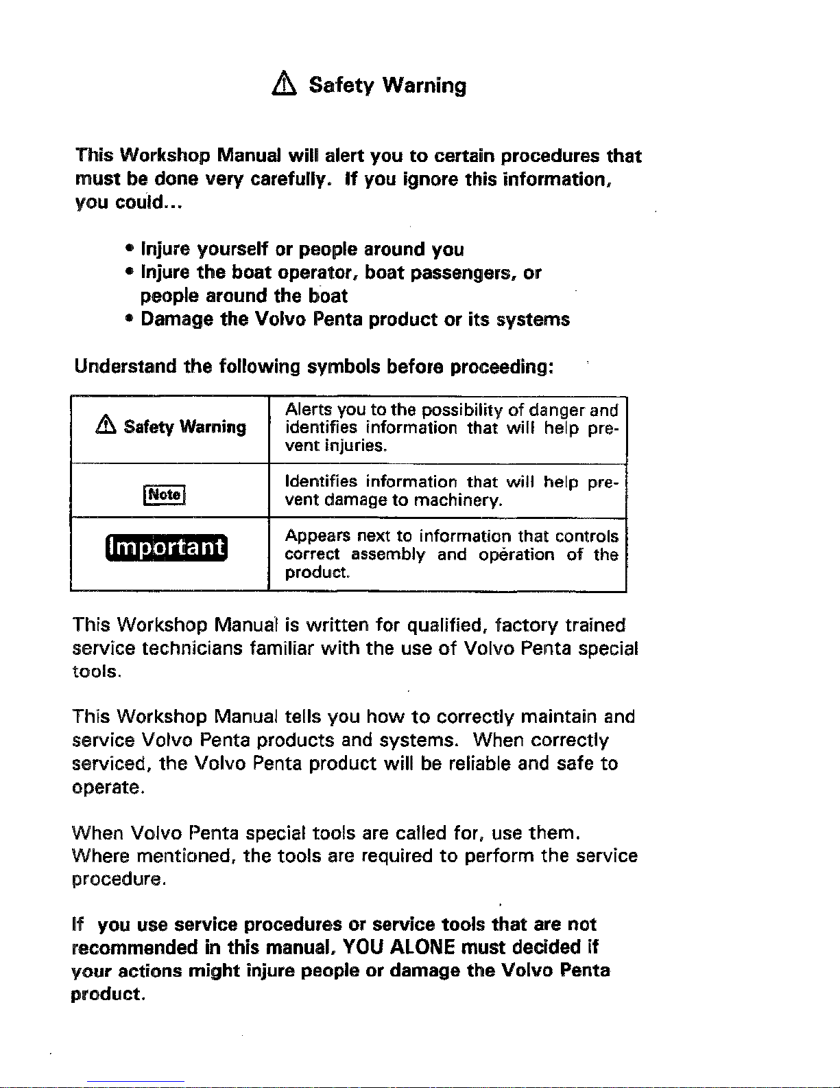
Understand the following symbols before proceeding:
Z~I Safety Warning
Alerts you to the possibility of danger and
identifies information that will help pre-
vent injuries.
identifies information that will help prevent damage to machinery.
Appears next to information that controls
correct assembly and operation of the
product.
This Workshop Manual is written for qualified, factory trained
service technicians familiar with the use of Volvo Penta special
tools.
This Workshop Manual tells you how to correctly maintain and
service Volvo Penta products and systems. When correctly
serviced, the Volvo Penta product will be reliable and safe to
operate.
When Volvo Penta special tools are called for, use them.
Where mentioned, the tools are required to perform the service
procedure.
If you use service procedures or service tools that are not
recommended in this manual, YOU ALONE must decided if
your actions might injure people or damage the Volvo Penta
product.
Page 3
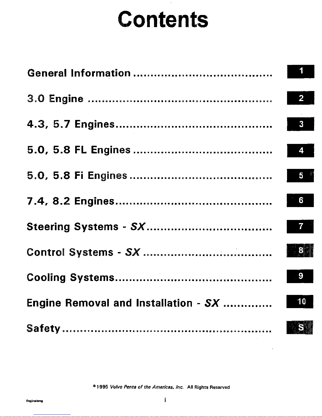
Contents
General Information ........................................
3.0 Engine ............... . .....................................
4.3, 5.7 Engines .......................... . ..................
5.0, 5.8 FL Engines ........................................
5.0, 5.8 Fi Engines .........................................
7.4, 8.2 Engines. ......................... ......... ......... .
Steering Systems - SX ....................................
Control Systems - SX .....................................
Cooling Systems ....
.... .................. .......... .........
Engine Removal and Installation - SX ..............
Safety ...............
..... ..................... . ..................
© 1995 Volvo Penta of the Americas, Inc. All Rights Reserved
i
Page 4
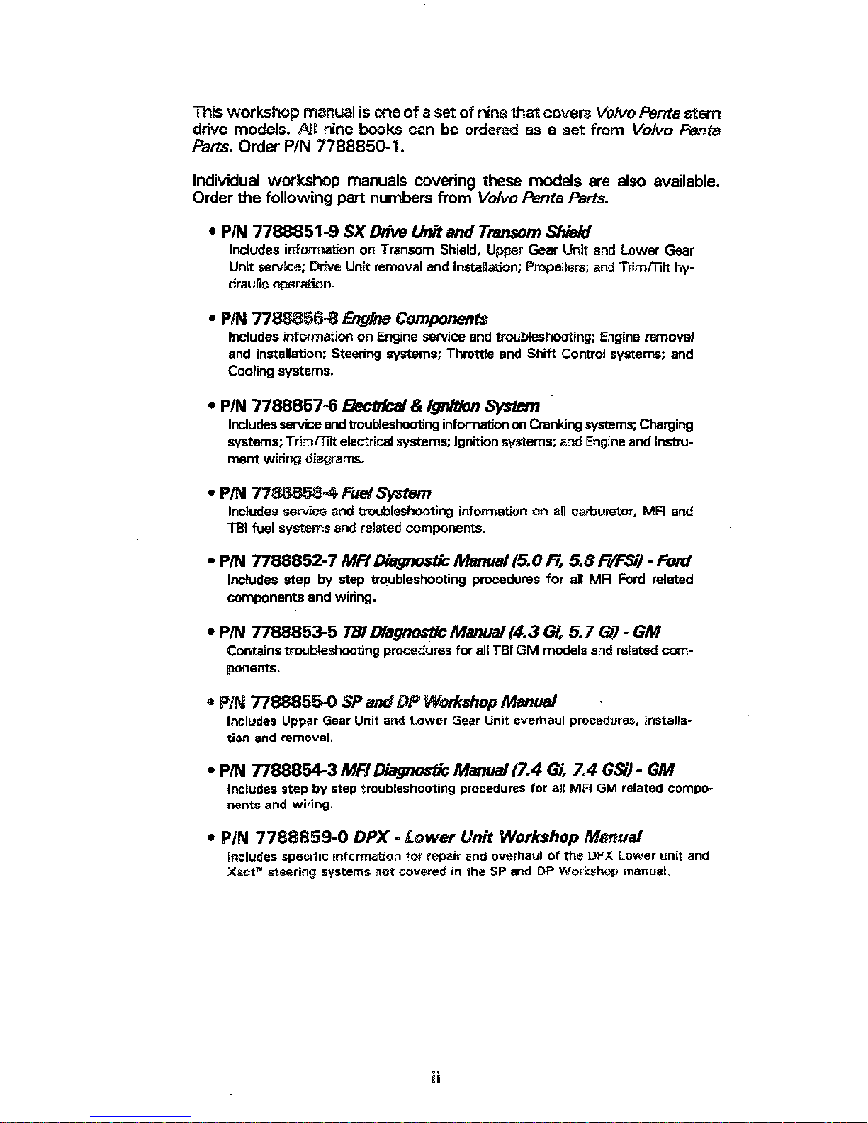
This workshop manual is one of a set of nine that covers Volvo Penta stem
drive models. All nine books can be ordered as a set from Volvo Penta
Parts. Order P/N 7788850-1.
Individual workshop manuals covering these models are also available.
Order the following part numbers from Volvo Penta Parts.
® P/N 7788851-9 SX Dfve Unit and Transom Shield
Includes information on Transom Shield, Upper Gear Unit and Lower Gear
Unit service; Drive Unit removal and installation; Propellers; and Trim/Tilt hy-
draulic operation.
® P/N 7788856-8 E~g/ne Components
Includes information on Engine service and troubleshooting; Engine removal
and installation; Steering systems; Throttle and Shift Comrol systems; and
Cooling systems.
¯ P/N 7788857-6 BectffcN &/gnit~n System
IncJudes service and troubleshooting information on Cranking systems; Charging
systems; Trim/Tilt electrical systems; Ignition systems; and Engine and Instrument widng diagrams.
¯ P/N 7788858-4 Furl System
Includes service and troubleshooting information on all carburetor, MR and
TB! fuel systems and related components.
¯ P/N 7788852-7 MR L~’agno~ Manual (5.0 R, 5.8 F~:Si) - Ford
Includes step by step troubleshooting procedures for all MFI Ford related
components and wiring.
, P/N 7788853-5 TBIDiagimsti
c"
Manual (4.3 G~ 5. 7 Gi) -
Contains troubleshooting procedures for all TBI GM models and related cornponents.
® P/N 77888550 SP and DP Workshop Manual
Includes Upper Gear Unit and Lower Gear Unit overhaul procedures, installa-
tion and removal.
, P/N 7788854-3 MR Diagnostic Manual (7.4 Gi. Z4 G~) -
includes step by step troubleshooting procedures for all MFi GM related components and wiring,
¯ P/N 7788859-0 DPX- Lower Unit Workshop Manual
includes specific information for repair and overhaul of the DPX Lower unit and
Xact
TM
steering systems not covered in the SP and DP Workshop manual°
ii
Page 5
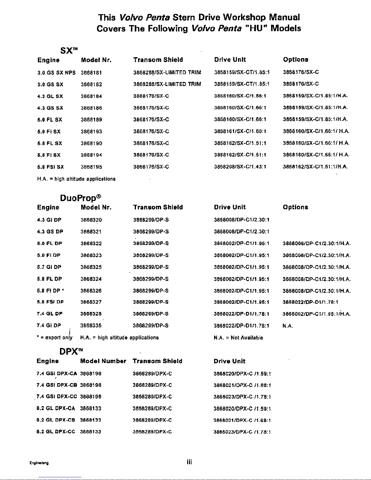
This Volvo Penta Stern Drive Workshop Manual
Covers The Following Volvo Penta "HU" Models
SX
~,
Engine
Model Nr.
Transom Shield
3.0 GS SX NPS 3868181
38682881SX-LIMITED TRIM
3,0 GS SX 3868182
3868288/SX-LIMITED TRIM
4.3 GL SX 3868184 3868176/SX-C
4.3 GS SX 3868186 3868178/SX-C
5,0 FL SX 3868189
38681761SX-C
6,0 Fi SX
3868193
3868176/SX-C
6=8 FL SX 3868190 3868176/SX-C
5.8 FI SX 3868194 38681761SX-C
5.8 FSi SX 3868195 3868176/SX-C
H.A. = high altitude applications
DuoProp
®
Engine Model Nr. Transom Shield
4.3 Gi DP 3868320 38682991DP-S
4.3 GS DP 3868321
3868299/DPOS
5.0
FL DP
3868322 38682991DP-S
5.0 F| DP 3868323 3868299/DP-S
5.7 Gi DP
3868325
3868299/DP-S
5.8 FL DP 3868324 3868299/DP-S
5.6 Fi DP * 3868326 38682991DP-S
5.8 FSi DP 3868327 3868299/DP-S
7.4 GL DP
3868328 38682991DP-S
7.4 G| DP 3868335 38682991DP-S
t
" = export on!y H.A. = high altitude applications
DPX
~
Engine
Model Number Transom Shield
7.4 GSi DPX-CA 3868198
3868289/DPX-C
/
7.4 GS| DPX-CB3868198 38682891DPX-C
7.4 GSi DPX-CC3868198 3868289/DPX-C
8.2 GL DPX-CA 3868133 3868289/DPX-C
8.2 GL DPX-CB 3868133 3868289/DPX-C
8.2 GL DPX-CC 3868133 38682891DPX-C
Drive Unit
3868159/SX-CTIl.85:l
3868159/SX-CT/l.85:l
38681601SX-C/1.66:1
3868160/SX-Cll .66"1
3868160/SX-C/1.66:1
38681611SX-CI1.60:1
38681621SX-C/1.51:1
38681621SX-CI1.51:1
38682081SX-CI1.43:1
Drive Unit
3868008/D P-C 112.30:1
3868008/D P-C 112.30:1
3868002/DP-Cl!1.95:1
38680021DP-Cl/1.95:1
38680021DP-C 1/1.95:1
38680021DP-C 1/t .95:1
3868002/DP-Cl11.95:1
38680021DP=Cl/1.95:1
3868022/DP-D111.78:1
38680221DP-DlI1.78:l
N.A. = Not Available
Drive Unit
38680201DPX-C/1.59:1
3868021/DPX-C I1 °68:1
3868023/DPX-C/1,78:1
3868020/DPX-C 11.59:1
38660211DPX-C I1.68:1
3868023/DPX-C I1 o76:1
Options
3868176/sx-c
3868t76/SX-C
3868159/SX-C/1.85:llH.A.
3868159/SX-C/1.85:11H.A.
38681591SX-CI1.85:11H.A.
38681601SX-CI1.66:11 HoA.
3868160/SX-CI1.66:11 H.A.
38681601SX.CI1.68:11 H.A.
3868162/SX-C/1.51:l/H.A.
Options
3868008/DP-C 1/2.30:1/H.A.
38680081DP-CII2.30:llH.A.
3868008/DP-C1/2.30:11H.A.
38680081DP-C1/2.30: l lH.A.
3868008/DP-C l12.30: l lH.A.
38680221DP-D1/1.78:1
38680021D P-C 1/1.95: I/H,A.
N.A.
Page 6
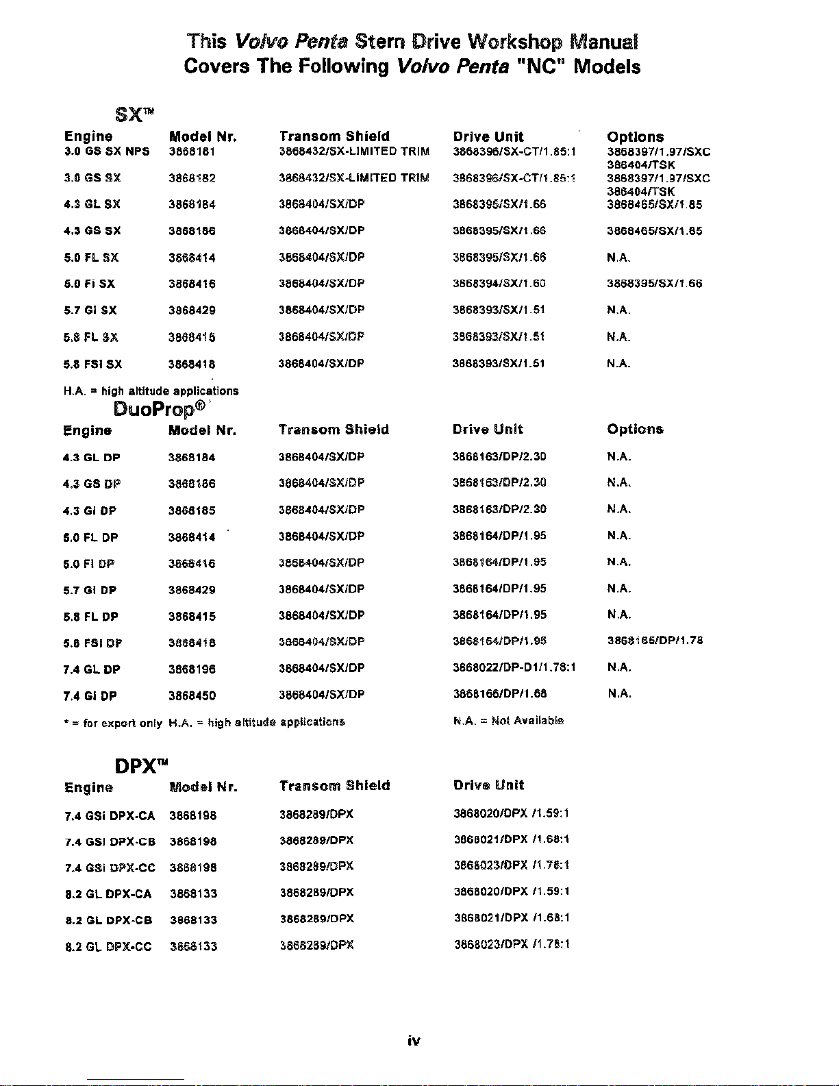
This Volvo Penta Stern Drive Workshop Manual
Covers The Following Volvo Penta "NC" Models
SX"
Engine
3.0 GS SX NPS
3.0 GS SX
4.3 GL SX
4.3 GS SX
5.0 FL SX
5.0 Fi SX
6.7 Gi SX
5.8 FL SX
6.8 FSi SX
Model Nr. Transom Shield Drive Unit
3868181 36684321SX-LIMITED TRIM 38683961SX.CTI1.85:l
3868182
38684321SX-LIMITED TRIM
38683961SX-CTI1.85:l
3868184 38684041SXIDP 3868395/SXll .66
3868186 38684041SXIDP 3868395/SXI1 °66
3868414 3868404/SXIDP 38683951SX/1.66
3868416 38684041SXIDP 3868394/SXl1.60
3868429 38684041SX/DP 3668393/SXI1.51
3868415 38684041SXIDP 3868393/SXI1.51
3868418
38684041SXIDP 38683931SXI1.5t
H.A. = high altitude applications
DuoProp
®’
Engine Model Nr. Transom Shield
4.3 GL DP
3868164
38684041SX/DP
4.3 GS DP 3868186
38684041SXIDP
4.3 Gi DP
3868185 38684041SX/DP
6.0 FL DP 3868414
38684641SXIDP
5.0 Fi DP
3868416 38684041SXIDP
6.7 Gi DP
3868429 3668404/SX/DP
8.8 FL DP 3868415
38684041SXIDP
5,8 FSi DP 3868418
38684041SXIDP
7.4
GL DP
3868196
38684041SXIDP
7.4 Gi DP 3868450
38684041SX/DP
* = for export only H.A. = high altitude applications
Drive Unit
3868163/DPI2.30
38681631DPI2.30
38681631DPI2.30
38681641DPI1.95
3868164/DPll .95
38681641DP/1.95
38681641DPIl.g5
3868164/DP/1.95
3868022/DP-D111,78:1
3868166/DPI1.68
N.A. = Not Available
Options
386839711.97/SXC
386404/TSK
386839711.971SXC
386404/TSK
3868465/SXl1.85
3868465/SXI1.65
N.A.
3868395/SXll .66
N.A.
N.A.
N.A.
Options
N.A.
N.A.
N.Ao
N.A.
N.Ao
N.A.
N.A.
38681651DPII.78
N.Ao
N,A.
Engine Model Nr.
Transom Shield
7.4 GSi DPX-CA 3868198
3868289/DPX
7.4 GSi DPX-CB 3868198
38682891DPX
7.4 GSi DPX-CC 3868198
38682891DPX
8.2 GL DPX-CA 3868133
38682891DPX
8.2 GL DPX-CB 3868133
38682891DPX
8.2 GL DPX-CC 3868133
38682891DPX
Drive Unit
38680201DPX 11.59:1
38680211DPX 11,68:1
38680231DPX It ,78:1
3868020/DPX 11.59:1
38680211DPX 11.68:1
38680231DPX 11.78:1
iv
Page 7

Section 1
General Information
Table of Contents
Belt Adjustments
Alternator ....................................
1-24
Power Steering ................................ 1-22
Raw-water Pump ............................... 1-24
Belt Tension .................................... 1-21
Compression Pressure Limit Chart ................... 1-7
conversion Charts
Drill ......................................... 1-39
Metric ....................................... 1-38
Crankcase Oil ................................... 1-9
Engine Break-in ..................................
1-18
Engine compression Testing ........................
1-5
Engine Troubleshooting Guides .....................
1-26
Gasolines Containing Alcohol .......................
1-8
Gasoline Requirements ............................
1-8
Introduction ....................................
1-2
Lubrication
Inspection Chart ...............................
1-41
Steering System ............................... 1-11
Off-Season Storage Preparations .................... 1-11
Oil Filter ....................................... t-10
Power Steering Ruid Level .........................
1-11
Power Trim/Tilt Fluid Level - SX Models ......... ......
1-11
Preparation for Boating After Storage ................
1-17
Submerged Engine ...............................
1-20
Symbols .......................................
%40
Torque Specifications, General ......................
1-37
Troubleshooting - System Isolation ..................
1-25
Tune-up Specifications ............................
1-33
Tuning the Engine ................................
1-5
20-Hour Check ..................................
1-20
Safety Warning
Before working on any part of an Volvo Penta®stern drive, read
the section called Safety at the end of this manual.
Page 8

introduction
This workshop manual covers Volvo Penta stern drive models. It is
divided into sections concerning various systems and assem-
blies. Refer to the Contents to locate the section covering the
system or assembly requiring service. Each section title page has
an additional listing that will describe the section’s contents in
more detail. Be sure to read the Safety Section at the end of this
manual, and pay special attention to all safety warnings as they
appear throughout the text. Since models are subject to change at
any time, some photos may not depict actual product.
Good Service Practice
Service required for Volvo Penta stern drives is generally one of
three kinds:
Normal care and maintenance -which includes putting a
new stern drive into operation, storing engines, lubrication, and care under special operating conditions such as
salt water and cold weather.
e Operating malfunctions - due to improper engine or
drive mounting, propeller condition or size, boat condition, or the malfunction of some part of the engine. This
includes engine servicing procedures to keep the engine
in prime operating condition.
¯
Complete disassembly and overhaul - such as major
service or rebuilding a unit.
It is important to determine before disassembly just what the
trouble is and how to correct it quickly, with minimum expense to
the owner.
When repairing an assembly, the most reliable way to ensure a
good job is to do a complete overhaul on that assembly, rather
than just to replace the bad part. Wear not readily apparent on
other parts could cause malfunction soon after the repair job.
Repair kits and seal kits contain all the parts needed to ensure a
complete repair, to eliminate guesswork, and to save time.
Repair time can also be minimized by the use of special tools.
Volvo Penta special tools are designed to perform service pro-
cedures unique to the product that cannot be completed using
tools from other sources. They also speed repair work to help
achieve service fiat rate times. In some cases, the use of substi-
tute tools can damage the part.
Do not operate engine out of water even momentarily, if
operated in test tank, use proper test wheel. Failure to do so can
damage raw-water pump, overheat engine, or allow excessive
engine RPM.
Page 9

Preparation for Service
Proper preparation is extremely helpful for efficient service work.
A clean work area at the start of each job will minimize tools and
parts becoming misplaced. Clean an engine that is excessively
dirty before work starts. Cleaning will occasionally uncover
trouble sources. Obtain tools, instruments and parts needed for
the job before work is started. Interrupting a job to locate special
tools or repair kits is a needless delay.
Z~ Use proper lifting and handling equipment. Working on stern
drives without proper equipment can cause damage and personal injury.
Always use clean fresh fuel when testing engines. Troubles can
often be traced to the use of old or dirty fuel.
Service Policy
Whether within or following the warranty period, Volvo Penta has
a constant interest in their products.
It is Volvo Penta’s policy to provide dealers with service knowl-
edge so they can give professional service demanded by today’s
consumer. The Volvo Penta Service Schools, frequent mailing of
Service Bulletins, Letters and Promotions, Special Tools and this
Workshop Manual represent Volvo Penta’s efforts to assist deal-
ers in giving consumers the best and most prompt service
possible. This Workshop Manual covers all phases of servicing
the Volvo Penta stern drive unit. If a service question does not
appear to be answered in this manual, you are invited to write to
the Volvo Penta Service Department for additional help. Always
be sure to give complete information, including engine model
number and serial number.
Be sure that you are familiar with Volvo Penta’s Warranty. if you
have any questions, write the Volvo Penta Service Department. If
other than genuine Volvo Penta replacement components or parts
are used, Volvo Penta may refuse subsequent warranty claims
involving that engine.
When a brand-name product or specific tool is called for, another
item may be used. However, the substitute must have equivalent
characteristics, including type, strength, and material. You must
determine if incorrect substitution could result in product mal-
function and personal injury to anyone. To avoid hazards, equiva-
lent products which are used must meet all current U.S. Coast
Guard Safety Regulations and ABYC standards.
Page 10

Replacement Parts
/~ When replacement parts are required, always use genuine
Volvo Penta parts, or parts with equivalent characteristics, in-
cluding type, strength, and material. Failure to do so may result
in product malPdnclion and possible injury to the operator and/or
passengers.
Parts Catalogs
/~ Parts Catalogs are a good source of information for ordering
parts. They are NOT a good source for disassembly and reas-
sembly of the engines and drives. The exploded views in g-~
Parts Catalogs are for illustxal~on of parts only, not a source of
assembly ins~uctJons. The workshop manual has det=led information and is the only source of inforn~on for disassembly and
reassembly.
Fagure to fogow workshop manuai ~ and
cau~ns may result in dea~, pemonal injury to
yourself or bystanders and damaged equipment.
Special Service Tools
Volvo Penta has specially designed tools to simplify disassembh/
and reassembly operations. These tools are illustrated in this
Workshop Manual. All Volvo Penta special tools can be ordered
from Volvo Penta Parts Department. Non-dealer users of Work-
shop Manuals must order Special tools through and authorized
Volvo Penta Dealer.
Product References, Illustrations and Specificadons
Volvo Penta reserves the right to make changes at anytime, with-
out notice, to specifications, models, and procedures. Also, the
fight to change any specifications or parts at any time without
incurring any obligation to equip same on models manufactured
prior to date of such change. All information, illustrations and
specifications, contained in this manual are based on the latest
product information available at the time of printing. The right is
reserved to make changes at any time without notice.
Photographs and illustrations used in this manual may not depict
actual models or equipment. The continuing accuracy of this
manual cannot be guaranteed.
Safety Related
1-4
Page 11

Tuning The Engil~
The purpose of an engine tune-up is to restore power and performance that has been lost through wear and deterioration of one or
more components. In the normal operation of an engine, these
changes can take place gradually at a number of points. It is seldom
advisable to attempt improvement in performance by correcting one
or two items only. Lasting results will be obtained by following a
definite and thorough procedure of analysis and correcting all items
affecting power and performance.
Economical, dependable operation can be ensured if a complete
tune up is performed once every boating season, preferably at the
beginning of the season when boat is brought out of off season
storage. Components that affect power and performance can be
divided into three groups:
e Components affecting compression
¯ Components affecting ignition
eComponents affecting fuel system
Procedures for performing a complete engine tune-up will be covered in this manual.
Engine Compression Tesling
1. Compression Check: Proper compression is essential for good
engine performance. An engine with low or uneven compression
cannot be properly tuned.
AWAR~ Use~c~earomTd~3~ew/~nx~vgorc~r-
/rig. Remove/oose do~i~g andjewe/ty to prevent
entangleme~ wiU~ rotating pulleys and ddve belts.
a. Run engine up to normal operating temperature.
Engine must NOT be started and run without water for
cooling.
Page 12

b. Remove any foreign matter from around spark plugs
by blowing out with compressed air.
WARNING Heating and eye protecO’on required to prevent injury
while using compressed air.
c.
Remove and inspect all spark plugs. Install thread
type compression gauge in spark plug hole.
d. To Prevent Sparking:
¯
3.0, GS, 4.3 GL, GS, Gi, 5.7 Gi, and 7.4 Gi, GSi
Models - remove 2-wire connector from d’~uibutor.
¯
5.O, 5.8 FL, and 7.4, 8.2 GL Models - remove both
distributor primary wires from th~ ignition coil, and
tape wire terminals to prevent accidental grounding.
¯
5.0, 5.8 Fi, FSi Models - unplug 2-way connector
at ignition coil.
e. With choke and throttle plates wide open, crank engine
through at least four compression strokes, or until compression gauge reading stops rising.
Test Conclusion
The indicated compression pressures are considered normal if the
lowest reading cylinder is within 75% of the highest reading cylinder.
Example:
if the highest pressure reading was 140 psi, 140 X .75 = 105.
Therefore, any cylinder reading less than 105 psi indicates valve,
piston, or piston ring problems.
if one or more cylinders read low, squirt approximately one tablespoon (25 ml) of engine oil in the cylinders with the low readings.
Repeat test on the cylinders with low readings. This is commonly
referred to as a "Wet Test."
1. If compression improves considerably, the piston rings are at
fault.
2.
if compression does not improve, valves are seating poorly or
bumt valves are suspect.
if two adjacent cylinders indicate low compression pressures,
and a wet test does not improve compression on either cylinder, the head gasket may be leaking between the cylinders.
This problem may or may not be accompanied by coolant in
the cylinders. If coolant is discovered in the cylinders, this may
be cause for further investigation on fresh water cooled engines with unexplained coolant loss.
3.
A Safety Related
1-6
Page 13

it is recommended the following quick reference chart be used when checking cylinder compression
pressures. The chart has been calculated so that the lowest reading number is 75% of the highest
reading.
Compression Pressure Limit Chart
Max. Min.
PSR PSi
134 101
136 102
138 104
140 105
142 107
144 108
146 110
148 111
150 113
152 114
Max. Min.
PSI
PSI
154
115
156 117
158 118
Max. Min.
PSi PSi
174
131
176 132
178 133
Max.
Min.
PSI
PSi
194 145
196 147
198 148
200 150
202 151
204 153
206 154
208 156
210 157
212 158
160 120
162 121
164 123
166 124
168 126
170 127
172 129
180 135
182 136
184 138
186 140
188 141
190 142
192 144
After checking cylinder compression, repairs should be made as
necessary. Subsequent adjustments to an engine that does not
have proper compression will not measurably improve performance or correct operational problems. After verifying compres-
sion, check ignition and fuel system components.
¯ Spark Plugs
¯ Spark Plug Leads
¯ Distributor Cap
¯ Rotor
¯ ignition Coil
¯ High Tension Lead
¯ ignition Switch
¯ Circuit Wiring and Connectors
¯ ECM
¯
Fuel Tank Pickup and Screen
¯
Fuel Tank Vent
¯
Anti-Siphon Valve (if equipped)
¯
Fuel Octane and Quality
¯
Boat Fuel Lines and Valves
¯
External Engine Fuel Filter
¯ Fuel Pump and Line
¯
Carburetor Fuel Filter or Screen
¯
Carburetor Adjustments
¯
Engine PCV Valve (if equipped)
¯
Flame Arrestor
¯
Pressure Regulator and injectors
¯
TB! Unit
All of the above listed components are not necessarily part of an
engine tune-up, but must be considered when attempting to
correct engine/boat performance problems. Repair or replace
components only as required.
___~ Do not substitute automotive parts. Volvo Penta marine
components meet U.S. Coast Guard regulations for external
ignition proof operation and marine use. Volvo Penta marine
components are specially designed not to cause ignition of fuel
vapors in the bilge or engine compartment The use of automotive parts can result in fire and explosion,
s~+.~,~ Z~ Safety Related
1-7
Page 14

Gasoline Requirements ,
Volvo Penta models are designed for maximum performance with the
use of lead-free gasoline with the following minimum or higher octane
specification:
Inside the U.S., (R + M)/2 (AKI)
Outside the U.S., (RON) -
4.3 GL Models - The ignition timing will have to be retarded if lower
octane fuels, with minimum 86 AKI {90 RON) octane, are used. Refer
to "Timing" in Tune-up Specifications. When ignition timing is retarded,
a slight decrease in power can be expected.
Use of gasoline with lower than 89 AKI (93 RON) octane in 4.3
models, without retarding ignition timing as specified, will result in seri-
ous damage to your engine and will void the engine warranty.
All Other Models - Lower octane fuels, with minimum 86 AKI (90 RON)
octane, can be used. With the use of lower octane fuel, a slight decrease in power can be expected.
Engine damage resulting from the use of gasoline with octane
lower than 86 AKI {90 RON) is considered misuse of the engine and will
void the engine warranty.
Some marinas sell fuel with lead addles. Do not use leaded fuel as it
may plug the fuel injecton. Premium fuel contains injector cleaners and
other additives that protect the fuel system and provide optimum performance. The use premium grade fuels in all modds is s~ongly recom-
mended. To prevent gum formation and corrosion in the fuel system,
use Fuel Conditioner in the gasoline. Fuel Conditioner is available from
your Volvo Penta stem drive dealer.
i
A Gasoline is extremely flammable and highly explosive under cer-
tain conditions, Always stop engine and do not smoke or allow open
flames or sparks near the boat when refueling gas tanks. Sparks or
flames may cause an explosion resuking in personal injury.
A When filSng the gas tank, ground the tank to the source of gasoline
by hdc6ng the hose nozzle firmly against the side of the deck filler plate,
or ground it in some other manner. This action prevents static electricity
build-up which could cause sparks and ignite fuel vapors. Sparks or
flames may cause an explosion resulting in personal injury.
Gasolines Containing Alcohol
Many gasolines being sold today contain alcohol. Two commonly used
alcohol additives are Ethanol (ethyl alcohol} and Methanol (methyl alccP
hol).
A Safety Related
1-8
Page 15

See the boat’s Operators Manual to determine if the boat’s fuel
system is compatible with alcohol blended fuels. If it is, your
engine may use gasolines blended with no more than 10%
Ethanol (ethyl alcohol) meeting the minimum octane specification. Do not use any gasoline which contains METHANOL (meth-
yl alcohol).
[~ Continued use of METHANOL (methyl alcohol) fuel will
cause serious damage to the boat or engine fuel systems.
if you use gasoline containing alcohol, be aware of the following:
The engine will operate leaner. This may cause engine
problems such as vapor lock, low speed stalling, or hard
starting.
Alcohol blended fuels attract and hold moisture. Mois-
ture can cause fuel tank corrosion. Inspect fuel tanks at
least annually. Replace corroded or leaking fuel tanks.
¯
Frequently inspect non-metallic parts of fuel system and
replace if excessively stiff, deteriorated or leaking.
Z~ Fuel leakage can contribute to a fire and/or explosion.
Crankcase Oil
[~] Initial factory fill is a high quality motor oil for APi Service
SG/CD. During the break-in period (20 hours), frequently check
the oil level. Somewhat higher oil consumption is normal until
piston rings are seated. The oil level should be maintained in the
safe range between the Add and Full marks on the dipstick. This
range represents approximately 1 liter (1 quart), if it is necessary
to add or change the motor oil, use a quality oil with API service
category SG/CD that meets Genera/Motors Standard GM-6094-M
or Ford Specification ESE-M2C153-E. Volvo Penta DuraPlus
TM
Motor Oils are recommended.
At the end of the break-in period (20 hours), change the crankcase
oJi and replace the oil filter. Refer to Lubrication and Inspection
Chart for recommended oil change intervals.
The use of multi-viscosity oils, such as 10W-30 or 10W-40,
is not recommended.
Draining and Riling the Engine Crankcase
Drain and refill crankcase every 100 hours of operation or once a
season, whichever occurs first.
Z~ To prevent fire and explosion, always make sure engine
compartment is free of gasoline fumes before using any spark-
producing tools such as the electric drill motor used with oil
withdrawal pump kit. Fire and explosion can result in personal
injury.
Page 16

~ Check the motor oil frequently. When oil is to be
changed, remove dipstick and draw oil from crankcase through dipstick t"ube with a suction pump. The dipstick tube is intended to be
used for drainage of the engine oil so it will not have to be drained into
the bilge.
Fill the crankcase to recommended capacity with a quality motor oil
labeled for SAE service category SG which meets General Motors
Standard GM-8094-M or Ford Specification ESE-M2C153-E. Oils
conforming to this standard contain detergent and anti-wear additives
that will prolong engine life. Volvo Penta Dura Plus
TM
Synthetic Motor
Oil P/N 3851230-7 exceeds both manufacturers standards.
When changing motor oil, select the viscosity that matches the ternperature range in which the boat will be operated. Use the same
viscosity when adding motor oil, do not mix different viscosity oils.
32°F (O°C) and above
SAE 30
0°F (-18°C) to 32°F (0°C)
SAE 20W-20
Below 0°F (-’18°C)
SAE 10W
Do not fill above full mark. Overfilling results in high operating ternperatures, foaming the oil (mixing air in the oil), loss of power, and
reduced engine life.
3.0 GS ....
3.5 qts. (3,3 liters)
4.3 GL, GS, and Gi
4.0 qts. (3,8 liters)
5.0 FL
5.0 qts. (4,7 liters)
5.7 Gi
5.0 qts. (4,7 Riters)
5.8 FL
5.0 qts. (4,7 I~ers)
5.0 Fi
5.0 qts. (4,7 liters)
5.8 Fi, FSi
4.0 qts. (3,8 liters)
7.4, 8.2 GL
6.0 qts. (5,7 liters)
7.4 Gi, GSi
8.0 qts. (7,5 liters)
~th Filter
4.0 qts. (3,8 liters)
4.5 qts. (4,3 liters)
6.0 qts. (5,7 liters)
6.0 qts. (5,7 liters)
6.0 qts. (5,7 liters)
6.0 qts. (5,7 liters)
5.0 qts. (4,7 liters)
7.0 qts. (6,6 Eiters)
9.0 qts. (8,5 liters)
N
34101
..,~.: : ; ::. -_ ,_ ~,~._%,-~ " ~ ~ -’ - ’,;. 0,,~:% j:.~,._~ -~ l= .
[~ Replace the oil filter whenever the motor oil is changed. This
filter is a self-contained, screw-on type. To remove, unscrew filter
canister counterclockwise and discard. When attaching a new filter,
be sure the gasket is lightly lubricated with motor oil. Hand tighten
only, run engine and check for leaks. Do not run engine without
suppling cooling water. See Tunsmp $~~ns for model and
filter requirements. 1-~ 0
Page 17

Power Steering Fluid Level
[~ ~] Maintain the level With Volvo Penta power trin~ilt &
steering fluid. Approved power steering fluids such as GM power
steering fluid or Dexron II automatic transmission fluid can also
be used. Do not overfill the pump reservoir.
Steering System Lubrication
[~] [~ Every 60 days, grease the steering ram ~) with Volvo
Penta Grease.
Power Trim/Tilt-Fluid Level - SX Models
7L~_J At the beginning of each boating season, check the fluid
level in the reservoir as follows:
/~ The trim/tilt hydraulics are pressurized when the drive unit is
in the down position. The drive unit must be tilted fuji up to
relieve hydraulic pressure before removing level/fill plug (~.
Failure to tilt the drive unit to the full up position before
removing level/fi|l plug would result in a hazardous spray of
hydraulic oil. Caution should always be taken when removing
level/fill plug by placing 8 rag over the level/fill plug to prevent
residual pressure from spraying oil,
1. With the drive unit tilted full up, slowly and carefully remove
the level/fill plug.
2. Check the fluid level. The fluid should be level with the bottom
of the fill hole when the drive unit is at full tilt. If necessary, add
Volvo Penta power trim/tilt & steering fluid. Replace the level/fill
plug and tighten securely.
Off-Season Storage Preparations
[~ There are nine steps that must be completed for off-season
storage preparation.
Step 1. Condition Fuel System:
Add Fuel Conditioner to fuel system. Follow instructions for
adding conditioner and running engine as stated on the con-
tainer. This will stabilize the fuel and prevent formation of
varnish and gum in entire fuel system. Do this before continu-
ing with the following procedures.
[~ Models equipped with 4 BBL carburetors should be run
under a load at a high enough throttle setting to circulate
conditioner through the secondary fuel system.
E.~,~ ~ Safety Related
1-11
24074
COA6781A
Page 18

Step 2. Change Motor Oil and Oil Filter:
e Engine should first be operated under load until oil is
thoroughly warmed up. if oil is allowed to warm up
before draining, a more complete draining will be ac-
complished. In addition, accumulated impurities will be
held in suspension by the oil and be removed during
draining operation;
Remove motor oil by siphoning it out of oil withdrawal
tube. Follow the procedure under Draining and Filling
the Engine Crankcase.
Install a new oil filter and fill crankcase with recommended oil. With drive unit in full down position, run
engine at a fast idle for a few minutes to distribute clean
oil through engine.
Shut off engine and check oil level. Check oil filter gasket
for leaks. Add oil if necessary to bring oil level up to, but
not over, the full mark.
Drive unit must be submerged in water or an accessory
flushing adaptor must be used while operating engine.
When using a flushing adaptor, remove propeller before
starting engine to prevent accidental contact with moving
propeller. If propeller is not removed, personal injury may
result.
Step 3. Change Drive Unit Lubricant:
Drain and refill with fresh DuraPlus synthetic GL5gear oil. Refer
to Drive Unit Workshop Manual
Step 4. Fog Engine:
Carbureted and TBI Models
Warm up engine to ensure fuel conditioner is throughout
fuel system. Use 1,~ pint (0,24 litre) of Fogging Oil or
oz. (355 mi) spray can to fog engine.
e
Remove flame arrestor from carburetor. Following instructions on container, bring engine up to a fast idle and
slowly pour or spray % of fogging oil into carburetor.
Keep engine running while pouring fogging oil into
carburetor throat.
Rapidly add remaining 1~ of fogging oil to carburetor,
then reduce throttle to idle and let engine die. Turn off
ignition and replace flame arrestor. Close fuel shutoff
valve (if so equipped).
)/~ Safety Related
1-12
Page 19

Fi Models
Preparing an engine "storage mixture" in a six gallon fuel tank.
It must consist of a 5 gallons (! 8,9 liters) fuel; 4 pints (64 oz.,
1892.7 ml) Fogging Oil; and 1/3 cup (2.5 oz., 73.9 ml) Fuel
Conditioner. Mix these ingredients thoroughly.
¯
Disconnect fuel line at the engine. Connect the
"storage mixture" and run engine .for approxi-
mately 5 minutes at 1500 RPM. This will ensure
that all fuel systems and internal engine components are thoroughly protected. Shut off engine
before the "storage mixture" is depleted.
ACAUTION
Do not run engine out of fuel. The e/ectric fuel
pumps wJ be damaged~
Step 5. Drain Cooling System:
CAUTION When dra/n/ng en,~ne, ra~e orlower the bow to
engine in a ho~ontal plane. This wi
provide for complete drainage of block and mani-
folds, ff bow of boat is tu’gher or lower than
stern, some water may be trapped in the en~ne
Nock or mmdfoids. Improper or incomp~=W drain-
ing may result in freeze d~,nage to the en~e,
manifolds, drive unit or other components.
FREEZE DAMAGE IS NOT COVERED UNDER
VOLVO PENTA "S L/M/TED WARRANTY.
’~ nPt3
[~] Front
Loosen and slide clamp back. Remove and drain long hose
at thermostat housing.
Disconnect an drain large hose at circulating pump.
[~] Port
@ Remove exhaust manifold petcock stem. Clear hole with a
small wire to ensure complete drainage.
Remove cylinder block petcock stem. Clear hole with a
small Wire to ensure complete drainage.
34093
Front
Disconnect and drain long hose at thermostat housing.
® Disconnect and drain large hose at circulating pump.
1-13
Page 20

[~ Starboard
@ Loosen clamp and remove hose.
~) Remove cylinder block petcock stem.
wire to ensure complete drainage.
Port
® Loosen clamp and remove hose.
® Remove cylinder block petcock stem.
wire to ensure complete drainage.
Clear hole with a small
Clear hole with a small
~
5.0 and 5.8 Fi, FSi Models
Front
Disconnect the lower water bypass hose at large diameter of
check-valve.
¯
Drain or blow out check-valve and short hose to
thermostat housing.
¯ Drain or blow out long hose to fuel reservoir.
341O2
All 5.0 and 5.11 Models
Front
Disconnect and drain long hose at thermostat housing.
Disconnect an drain large hose at circulating pump.
Starboard
® Loosen clamp and remove rubber hose.
® Remove cylinder block petcock stem. Clear hole with small
wire to ensure complete drainage.
34161
34t34
 Loading...