

Volvo Penta D65A MS, D65A MT Workshop Manual

Workshop Manual
Plus d'informations sur : www.dbmoteurs.fr
D65A MS, D65A MT
H
2(0)

Plus d'informations sur : www.dbmoteurs.fr

Marine Engines
Plus d'informations sur : www.dbmoteurs.fr
D65A MS/MT
Content
Safety Information ................................................. 5
Warning labels ....................................................... 8
General Information ............................................ 10
Presentation ........................................................ 16
Identification numbers ......................................... 18
Specifications ...................................................... 19
Maintenance Standards Table ............................. 22
Tightening torques ............................................... 40
Sealants and Lubricants Table ............................ 46
Special Tools ....................................................... 47
Determination of overhaul timing ...................... 50
Adjustments and Benchtesting .......................... 51
Engine auxiliaries removal ................................. 61
Engine Auxiliaries Installation ............................ 73
Group 21:Engine Body
Cylinder heads and valve mechanism
Disassembly ........................................................ 77
Inspection and Repair .......................................... 80
Reassembly......................................................... 87
Cylinder liners, Pistons and Connecting rods
Disassembly ........................................................ 91
Inspection and Repair .......................................... 95
Reassembly....................................................... 104
Viscous damper and front gears
Disassembly ...................................................... 108
Inspection and Repair ........................................ 111
Reassembly....................................................... 113
Oil pan and Oil strainer ........................................ 115
Flywheel, Timing gears, and Camshaft
Disassembly ...................................................... 117
Inspection and Repair ........................................ 120
Reassembly....................................................... 124
Crankcase, Crankshaft and Main bearings
Disassembly ...................................................... 128
Inspection and Repair ........................................ 130
Reassembly....................................................... 137
Group 22:Lubrication system
Oil Pump and Safety Valve
Disassembly ...................................................... 139
Inspection .......................................................... 140
Reassembly....................................................... 142
Oil Filter, Relief Valve, Left Cooler and Thermostat
Disassembly ...................................................... 143
Inspection .......................................................... 144
Reassembly....................................................... 145
Right Side Oil Cooler and Oil Thermostat
Disassembly ...................................................... 146
Inspection .......................................................... 146
Reassembly....................................................... 146
Group 23:Fuel System
Fuel Filters
Disassembly ...................................................... 147
Reassembly....................................................... 148
Fuel Injectors
Disassembly ...................................................... 149
Inspection and Adjustment ................................ 150
Reassembly....................................................... 152
Fuel Injection Pump
Disassembly ...................................................... 153
Inspection .......................................................... 157
Reassembly....................................................... 160
Adjustment of Injection Timing ........................... 167
Feed Pump
Disassembly ...................................................... 169
Reassembly....................................................... 170
Testing .............................................................. 170
PSG Woodward Governor and Drive
Disassembly ...................................................... 171
Inspection .......................................................... 172
Reassembly....................................................... 173
3

Content
Plus d'informations sur : www.dbmoteurs.fr
Group 25:Inlet and Exhaust System
Air Cooler
Disassembly ...................................................... 174
Inspection .......................................................... 175
Turbocharger
Disassembly ...................................................... 177
Inspection .......................................................... 180
Reassembly....................................................... 182
Group 26:Cooling System
Fresh Water Pump
Disassembly ...................................................... 188
Inspection .......................................................... 190
Reassembly....................................................... 191
Thermostats ........................................................ 193
Heat Exchanger ................................................... 194
Raw Water Pump
Disassembly ...................................................... 195
Inspection .......................................................... 196
Reassembly....................................................... 197
Group 30:Electrical System
Starter
Disassembly ...................................................... 200
Inspection and Repair ........................................ 203
Reassembly....................................................... 207
Alternator
Disassembly ...................................................... 210
Inspection and repair ......................................... 211
Reassembly....................................................... 211
All rights reserved. Content subject to change without notice.
4
© 2003 AB VOLVO PENTA
Printed on environmentally friendly paper.
Safety information
Plus d'informations sur : www.dbmoteurs.fr
Safety Information
Introduction
The Manual contains technical data, descriptions, and repair instructions for the designated Volvo Penta engines
or engine versions. Make sure that the correct workshop literature is used.
Read the following safety information and the General Information and Repair Instructions in the Workshop Manual carefully before starting service work.
Important
The following special warning symbols are used in the Workshop Manual and on the engine.
WARNING! Warns of risk of bodily injury, serious damage to product or property, or that a serious malfunction can occur if the instructions are not followed.
IMPORTANT! Used to attract attention to things that can cause damage or malfunction to product or property.
NOTE! Used to attract attention to important information, to simplify work procedures or handling.
The following list provides an overview of the risks and cautionary procedures that should always be observed.
Prevent the engine from being started by disconnecting the power with the main switch
(switches) and locking it (them) in the disconnected position. Post warning signs stating
“Work in progress!” in every position from wich
the engine can be started.
Maintenance and service should be performed
on a stationary engine. However, some procedures, e.g. certain adjustments, require the engine to be running. Approaching an engine that
is running is a safety risk. Remember that loose
clothes or long hair can fasten in rotating parts
and cause severe injury.
A careless movement or dropped tool while
working in the vicinity of an engine that is running, can in the worst case lead to injury. Observe caution with hot surfaces (exhaust pipe,
turbo, charge air pipe, starter element etc.) and
hot fluids in the lines and hoses of an engine
that is running, or has just been stopped. Refit
all guards dismantled during service work before starting the engine.
Make sure that the warning or information decals on the product are always clearly visible.
Replace labels that have been damaged or
painted over.
Never start the engine unless the air filter is fitted. The rotating compressor wheel in the turbo
can cause severe injury. Foreign objects in the
inlet pipe can also damage the machine.
Never use starter spray or the like. Risk of in
the inlet pipe. Risk of personal injury.
Avoid opening the coolant filler cap when the
engine is hot. Steam or hot coolant can spray
out, and built up pressure will be lost. Open the
filler cap slowly and release the overpressure in
the cooling system if the filler cap or cock must
be opened, or if a plug or coolant pipe must be
removed when the engine is hot. Steam or hot
coolant can flow out in an unpredicted direction.
5
Safety information
Plus d'informations sur : www.dbmoteurs.fr
Hot oil can cause burn injuries. Avoid skin contact with hot oil. Make sure that the oil system is
not pressurised before working on it. Never
start, or run the engine with the oil filler cap removed due to the risk of ejecting oil.
Stop the engine and close the bottom valve before working on the cooling system.
Only start the engine in a well-ventilated area.
Exhaust fumes and crankcase gases should be
bled out of the engine compartment or workshop when working in closed environments.
Always use protective glasses for work where
there is a risk of splintering, sparks, or splashing of acid or other chemicals. The eyes are extremely sensitive, and an injury could cause
blindness!
Avoid skin contact with oil! Prolonged or frequent skin contact with oil can degrease the
skin, resulting in irritation, drying out, eczema,
and other skin complaints. Used oil is more
dangerous than new oil from a health care point
of view. Use protective gloves and avoid oildrenched clothes and rags. Wash your hands
regularly, especially before meals. Use special
hand cream to counteract drying out, and to
simplify cleaning the skin.
All fuels, as well as many chemicals, are inflammable. Make sure no naked flames or sparks
can cause ignition. Petrol, certain thinners, and
hydrogen from batteries are extremely inflammable and explosive when mixed with air.
Smoking is prohibited! Ventilate well and take
the necessary precautions before welding or
grinding in the immediate vicinity. Always have
a fire extinguisher handy in the workshop.
Make sure that rags drenched in oil and petrol,
including old fuel and lubricant filters, are stored
safety. Oil drenched rags can in certain conditions self-ignite. Old fuel and oil filters are environmentally hazardous waste, and together with
spent lubricant, contaminated fuel, paint residue, solvent, degreasing agent and suds,
should be handed in to a waste-handling unit for
destruction.
Batteries must never be exposed to naked
flames or electrical sparks. Never smoke in the
vicinity of batteries. Hydrogen develops when
batteries are charged, which in combination
with air forms an explosive gas. This gas is
highly inflammable and very explosive. One
spark from connecting the batteries incorrectly
is sufficient to cause the battery to explode and
cause injury. Do not touch the connection when
starting (risk of spark) and do not lean over the
batteries.
The majority of chemicals intended for the product (e.g. engine and timing gear oils, glycol,
petrol and diesel oil) or chemicals for workshop
use (e.g. degreasing agent, enamels and solvents) are hazardous to health. Read the instructions on the pack carefully. Always follow
the given safety instructions (e.g. the use of
breathing protection, protective glasses, or
gloves, etc.) Make sure that other personnel are
not exposed to hazardous substances, e.g. by
inhaling the air. Make sure there is adequate
ventilation. Handle consumed and surplus
chemicals in the prescribed manner.
Observe extreme caution when tracing fuel
leaks in fuel systems and when testing fuel nozzles. Wear protective glasses. The jet from a
fuel nozzle has a very high pressure and penetrating force. The fuel can penetrate deeply into
bodily tissue and cause serious injury. Risk of
blood poisoning.
Never confuse the plus and minus terminals
when fitting the batteries. This can cause serious damage to the electrical equipment. Check
the wiring diagram.
Always use protective glasses when charging
and handling batteries. The battery electrolyte
contains strongly corrosive sulphuric acid. Upon
contact with the skin, wash with soap and plenty of water. If battery acid gets into the eyes,
rinse immediately with water, and contact a
doctor without delay.
Stop the engine and turn off the power with the
main switch (switches) before working on the
electrical system.
The clutch should be adjusted when the engine
is idle.
6

Safety information
Plus d'informations sur : www.dbmoteurs.fr
Use the lifting hooks mounted on the engine/reversing gear when lifting the drive unit. Always
check that the lifting equipment is in good condition and has the correct capacity for the lift
(weight of engine plus reversing gear and extra
equipment where appropriate).
For safe handling, and to avoid damaging the
components mounted on top of the engine, the
engine should always be lifted with a lifting bar
adjusted to the engine. All chains or wires
should run in parallel with each other and as
perpendicular to the top of the engine as possible. Special lifting equipment may be required to
ensure the right balance and safe handling if
other equipment connected to the engine alters
its centre of gravity.
Never work on an engine supported only by lifting equipment.
Never work alone when heavy components are
to be dismantled, even when safe lifting (e.g.
lockable block and tackle) equipment is used. In
most cases, two persons are required even
when lifting equipment is used: one to handle
the equipment and one to make sure that components are not damaged. When working onboard a boat always make sure in advance that
there is sufficient space to allow dismantling in
situ, without the risk of personal injury or material damage.
WARNING! The components in the electrical
system and fuel system on Volvo Penta products are designed and manufactured to minimise the risks of explosion and fire. The engine
must not be run in environments surrounded by
explosive media.
Pressure pipes must not bent, turned, or exposed to other strain. Replace damaged pressure pipes.
Observe the following when cleaning with highpressure wash: Never point the jet of water at
seals, rubber hoses, or electrical components.
Never use the high-pressure function when
washing the engine.
Always use Volvo Penta recommended fuel.
See the instruction manual. The use of inferior
quality fuel could damage the engine. The use
of inferior fuel in a diesel engine could cause
the control rod to jam and the engine to overspeed, with the risk of personal injury or damage to the machine. Inferior fuel can also lead
to higher maintenance costs.
7
Safety information
Plus d'informations sur : www.dbmoteurs.fr
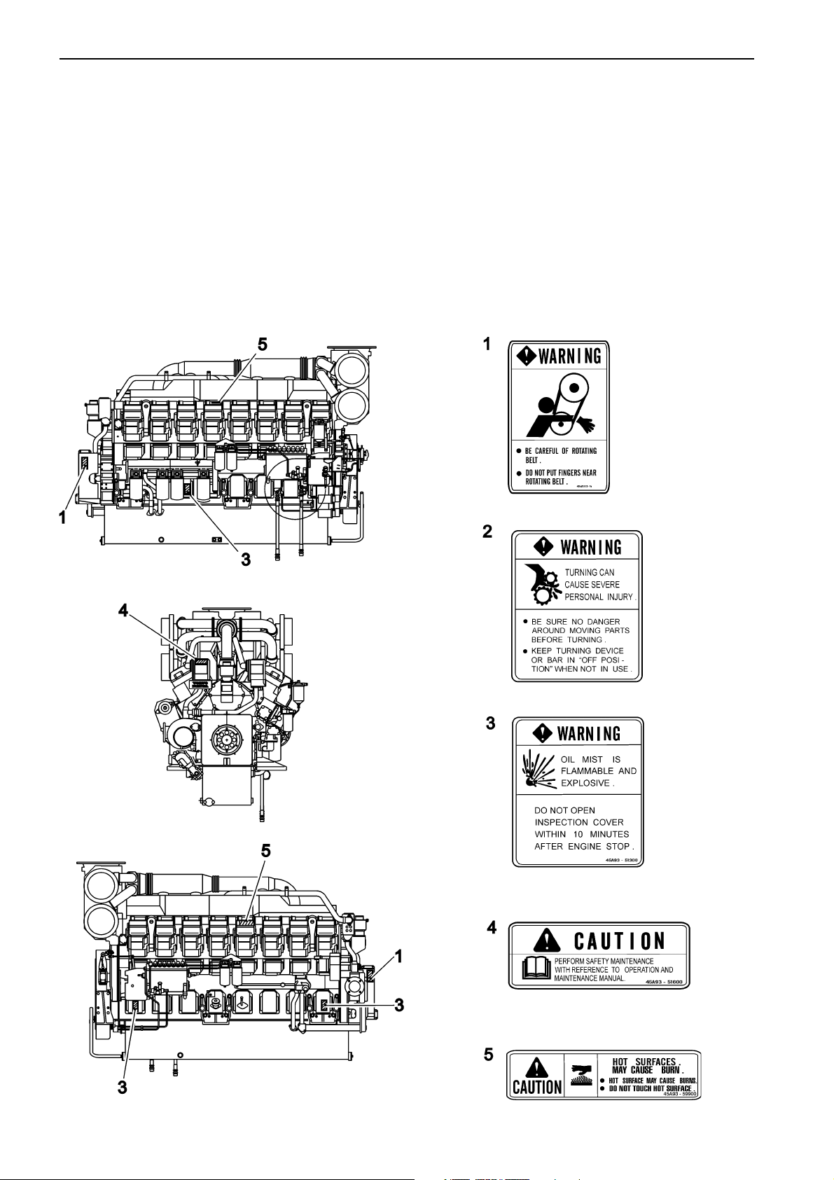
Warning labels D65A MS
The engine carries ‘Warning Labels’ at places where you are required to pay special attention. Please read
them carefully and make sure you understand the content of each label and the meaning of their position.
1. Make sure the labels are legible. If you find any letter or picture illegible in a label, remove soil from the
label, or replace it.
2. Clean the label with cloth and water or cleanser. Do not use organic solvent or gasoline, this would dissolve
the label’s adhesive and cause the label to fall off.
3. If any label is damaged, lost or illegible, replace it. When replacing a label, make sure the new label is
identical to the old one. For new labels, please contact your dealer.
8
Safety information
Plus d'informations sur : www.dbmoteurs.fr
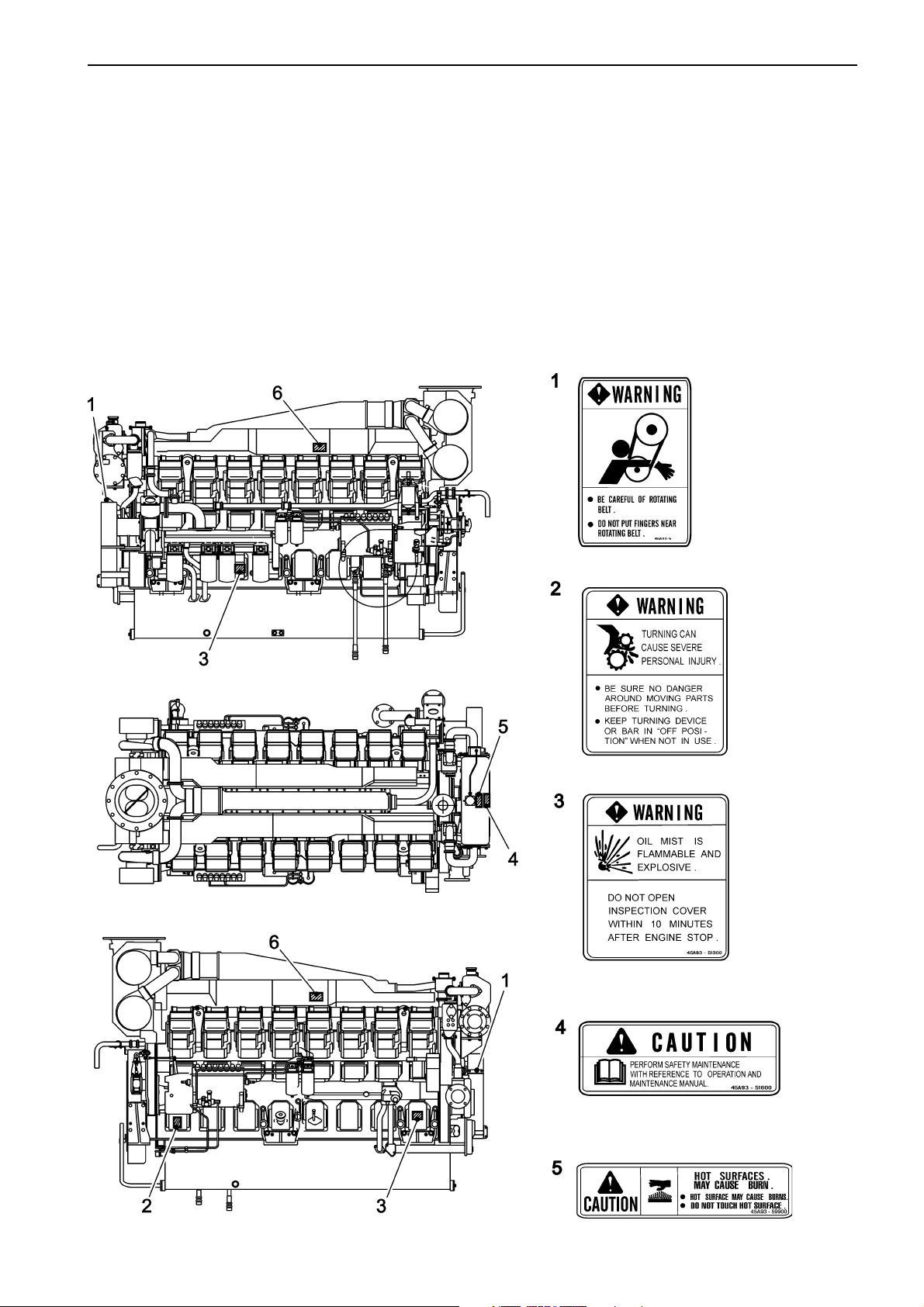
Warning labels D65A MT
The engine carries ‘Warning Labels’ at places where you are required to pay special attention. Please read
them carefully and make sure you understand the content of each label and the meaning of their position.
1. Make sure the labels are legible. If you find any letter or picture illegible in a label, remove soil from the
label, or replace it.
2. Clean the label with cloth and water or cleanser. Do not use organic solvent or gasoline, this would dissolve
the label’s adhesive and cause the label to fall off.
3. If any label is damaged, lost or illegible, replace it. When replacing a label, make sure the new label is
identical to the old one. For new labels, please contact your dealer.
9

General information
Plus d'informations sur : www.dbmoteurs.fr
General Information
About the Workshop Manual
This Workshop Manual contains technical information, descriptions, and instructions for the standard versions of
the D65A engines. The engine designation and numbers are to be found on the engine identification plate, refer
to section “Identification numbers”. The motor designation and number should always be given during all correspondence with Volvo Penta.
The Workshop Manual is primarily produced for Volvo Penta service workshops and their qualified personnel. It
is therefore assumed that persons using this manual have a basic knowledge of marine drive systems, and are
able to carry out the related mechanical and electrical nature. Volvo Penta is continuously developing their products. We therefore reserve the right to make changes. All the information contained in this book is based on
product data available prior to publication. Any essential changes or modifications in production or updated or revised service methods introduced after publication will be communicated by means of Service Bulletins.
Spare parts
Spare parts for the electrical and fuel systems are subject to different national safety requirements, e.g. U.S.
Coast Guard Safety Regulations. Volvo Penta Genuine Spare Parts comply with these requirements. All types of
damage resulting from the use of non genuine Volvo Penta spare parts for the product in question will not be regulated by the warranty undertakings of Volvo Penta.
Certified engines
For service and repair on an engine certificated for any area where exhaust emissions are regulated by law, the
following is important:
Certification means that an engine type is inspected and approved by the authorities. The engine manufacturer
guarantees that all engines manufactured of that type correspond to the certified engine.
This places special requirements on maintenance and service as follows:
●●
●
The maintenance and service intervals recommended by Volvo Penta must be observed.
●●
●●
Only genuine Volvo Penta replacement parts may be used.
●
●●
●●
The service of injection pumps and injectors or pump settings must always be carried out by an authorized
●
●●
Volvo Penta workshop.
●●
●
The engine must not be modified in any way except with accessories and service kits approved by Volvo
●●
Penta.
●●
No modifications to the exhaust pipes and air supply ducts for the engine may be undertaken.
●
●●
●●
Seals may only be broken by authorized personnel.
●
●●
Otherwise the general instructions contained in the Operator’s manual concerning operation, service and maintenance must be followed.
IMPORTANT! Neglected or deficient maintenance/service and the use of non-original spare parts will entail
Volvo Penta renouncing any responsibility for the engine corresponding to the certified version. Volvo Penta will not compensate for damage and/or costs arising from the above.
10

General information
Plus d'informations sur : www.dbmoteurs.fr
Repair instructions
The working methods described in the Service Manual apply to work carried out in a workshop. The engine has
been removed from the boat and is installed in an engine fixture. Unless otherwise stated reconditioning work
which can be carried out with the engine in place follows the same working method.
Warning symbols occurring in the Workshop Manual (refer to section “Safety information”) are not in any way
comprehensive since it is impossible to predict every circumstance under which service work or repairs may be
carried out. For this reason we can only highlight the risks that can arise when work is carried out incorrectly in a
well-equipped workshop using working methods and tools developed by us.
All procedures for which there are Volvo Penta special tools in this Workshop Manual are carried out using
these. Special tools are developed to rationalize working methods and make procedures as safe as possible. It is
therefore the responsibility of any person using tools or working methods other than the ones recommended by
us to ensure that there is no danger of injury, damage or malfunction resulting from these.
In some cases there may be special safety precautions and instructions for the use of tools and chemicals contained in this Workshop Manual. These special instructions should always be followed if there are no separate instructions in the Workshop Manual.
Certain elementary precautions and common sense can prevent most risks arising. A clean workplace and engine eliminates much of the danger of injury and malfunction.
It is of the greatest importance that no dirt or foreign particles get into the fuel system, cooling system, lubrication
system, intake system, turbocharger, bearings and seals when they are being worked on. The result can be malfunction or a shorter operational life.
Our joint responsibility
Each engine consists of many connected systems and components. If a component deviates from its technical
specification the environmental impact of an otherwise good engine may be increased significantly. It is therefore
vital that wear tolerances are maintained, that systems that can be adjusted are adjusted properly and that Volvo
Penta Genuine Parts as used. The engine Maintenance Schedule must be followed.
Some systems, such as the components in the fuel system, require special expertise and special testing equipment for service and maintenance. Some components are sealed at the factory for environmental reasons. No
work should be carried out on sealed components except by authorized personnel.
Bear in mind that most chemicals used on boats are harmful to the environment if used incorrectly. Volvo Penta
recommends the use of biodegradable degreasing agents for cleaning engine components, unless otherwise
stated in a workshop manual. Take special care when working on-board, that oil and waste is taken for destruction and is not accidentally pumped into the environment with bilge water.
11

General information
Plus d'informations sur : www.dbmoteurs.fr
How to Use This Manual
1. Parts in illustrations are numbered to correspond
with references to these numbers in text.
2. Items or conditions to be inspected during disassembly are listed in the disassembled views.
3. Maintenance standards for inspection and repair
are described in text where relevant. For a quick
summary of maintenance standards refer to section “Maintenance Standards” of this manual.
4. The sequence in which parts are to be reassembled is summarized below each assembled view.
Such as:
5. Tightening torque under wet conditions is indicated as “(wet)” in text, drawings, and tables. When
so indicated, apply engine oil to the threaded portion of the fastener. Unless indicated as (wet), the
tightening torque should be dry.
Terms used in this manual
Before you read this manual, note that the following
special terms are used in dimensional and other
specifications.
Assembly standard
Indicates the dimension of a part, the dimension to be
attained at the time of reassembly or the standard
performance.
Norminal value
Indicates the standard dimension of a part.
Repair limit
A part which has reached this limit must be repaired.
Service limit
A part which has reached this limit must be replaced.
Standard clearance
Indicates the clearance to be obtained between mating parts at reassembly.
12

General information
Plus d'informations sur : www.dbmoteurs.fr
Disassembly and Reassembly
This service manual covers recommended procedures to be followed when servicing diesel engines. It also contains information on special tools required and basic safety precautions.
It is the responsibility of service personnel to be familiar with these requirements, precautions, and potential hazards and to discuss these points with their foreman or supervisor.
Study this manual carefully and observe the following general precautions to prevent serious personal injury and
to avoid damage to the engine, equipment, and parts.
WARNING! Use the correct tools and instruments. Serious injury or damage to the engine can result from
using the wrong tools and instruments
WARNING! When lifting or carrying heavy parts, get someone to help you if the part is too awkward for one
person to handle. Use jacks and chain blocks when necessary.
IMPORTANT! Use an overhaul stand or work bench if necessary.
IMPORTANT! Always read the Service Bulletins to learn about changes in procedures and/or technical data.
NOTE! Pay attention to the marks on assemblies, components, and parts for positions or directions. Put on your
own marks, if necessary, to aid reassembly.
NOTE! Carefully check each part for faults during removal or cleaning. Signs of abnormal wear will tell if parts or
assemblies are functioning improperly.
NOTE! Use assembly bins to keep the parts in order of removal and lay down disassembled or cleaned parts in
the order in which they were removed. This will save you time at reassembly
NOTE! Wash all engine parts, except oil seals, O-rings, rubber seals, etc. in cleaning solvent and dry them with
compressed air
NOTE! Use a torque wrench to tighten parts when specified tightening torques are required.
NOTE! Use only good quality lubricating oils and greases. Be sure to apply a coat of oil, grease, or sealant be-
fore reassembly, to parts as specified.
NOTE! Replace all gaskets and packing. Apply appropriate amount of adhesive or liquid gasket when required.
NOTE! Always apply “high temperature anti-seizing compound” to bolts and nuts that are exposed to high tem-
peratures, e.g. exhaust manifold, turbo charger, exhaust flanges, etc.
13
General information
Plus d'informations sur : www.dbmoteurs.fr
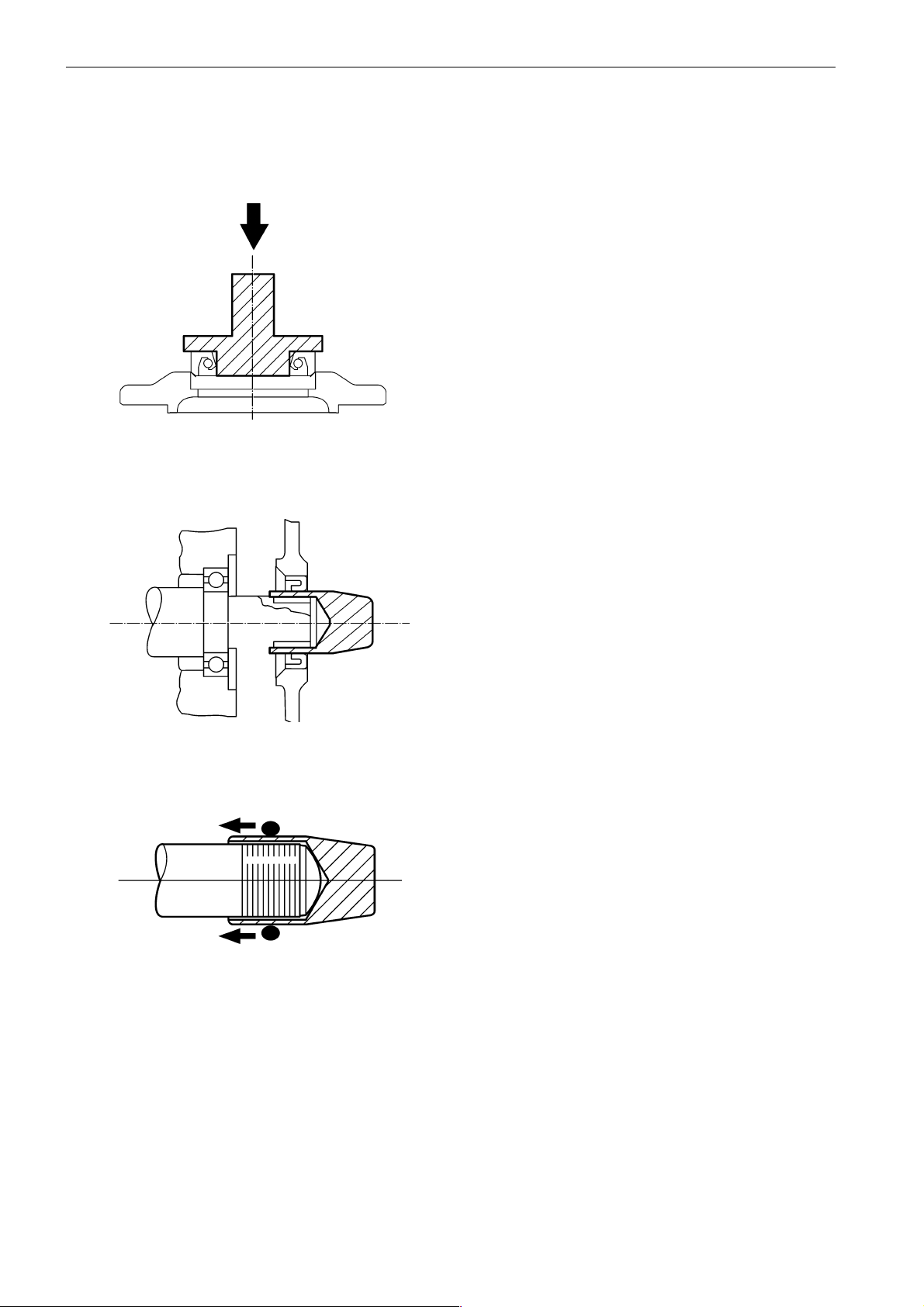
Oil Seals
When installing oil seals, carefully observe the following points.
Driving oil seals into housings
1. Check the seal lip for damage, and be sure to position correctly in the housing.
2. Apply a smear of grease to the surface of the oil
seal (to be fitted into the housing bore).
3. Use an oil seal driver shown to guide the seal lip
and drive the outer diameter squarely. To avoid
damage to the oil seal and leaking, never hammer on it directly.
Driving oil seals onto shafts
1. Apply a smear of grease to the oil seal lip.
2. Use an oil seal guide of the type shown when
driving the oil seal over the stepped portion,
splines, threads, or key way to prevent damage
to the oil seal lip.
O-rings
Use an O-ring guide to install an O-ring over stepped
parts, splines, threads, or key way to prevent damage
to the ring. Apply a smear of grease to the O-ring before installation.
14
General information
Plus d'informations sur : www.dbmoteurs.fr
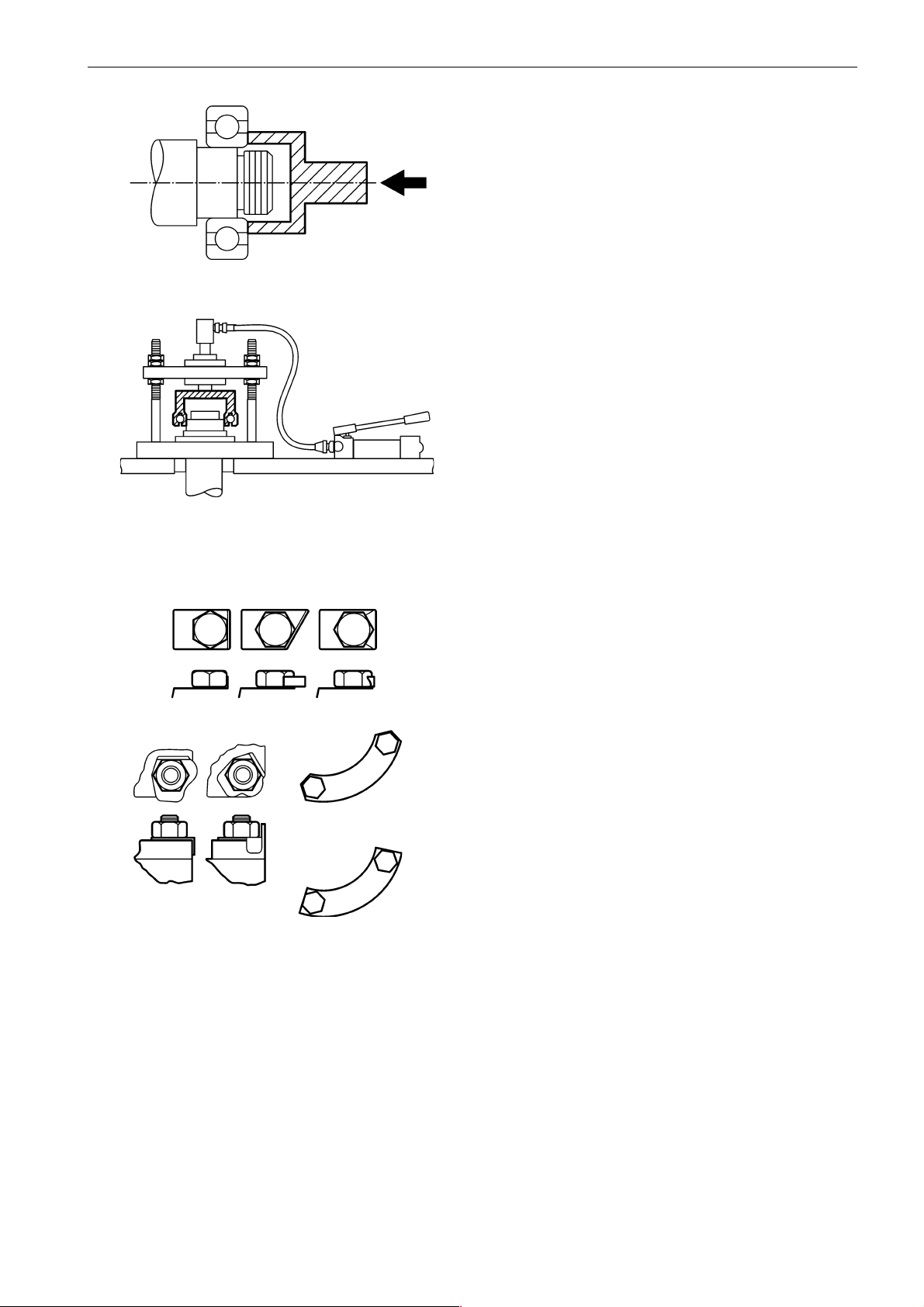
Bearings
1. When installing a rolling bearing, be sure to push
the inner or outer race by which the bearing is fitted. Be sure to use a bearing driver like the one
shown.
2. Whenever possible, use a press to minimize
shock to the bearing and to assure proper installation.
Lock Plates
Bend lock plates against the flats of the nuts or bolt
heads as shown.
Split Pins and Spring Pins
Generally, split pins are to be replaced once disturbed. Insert the pin fully and spread it properly.
Drive each spring pin into position to hold it in place
after later installation of parts has been completed.
15
General information
Plus d'informations sur : www.dbmoteurs.fr
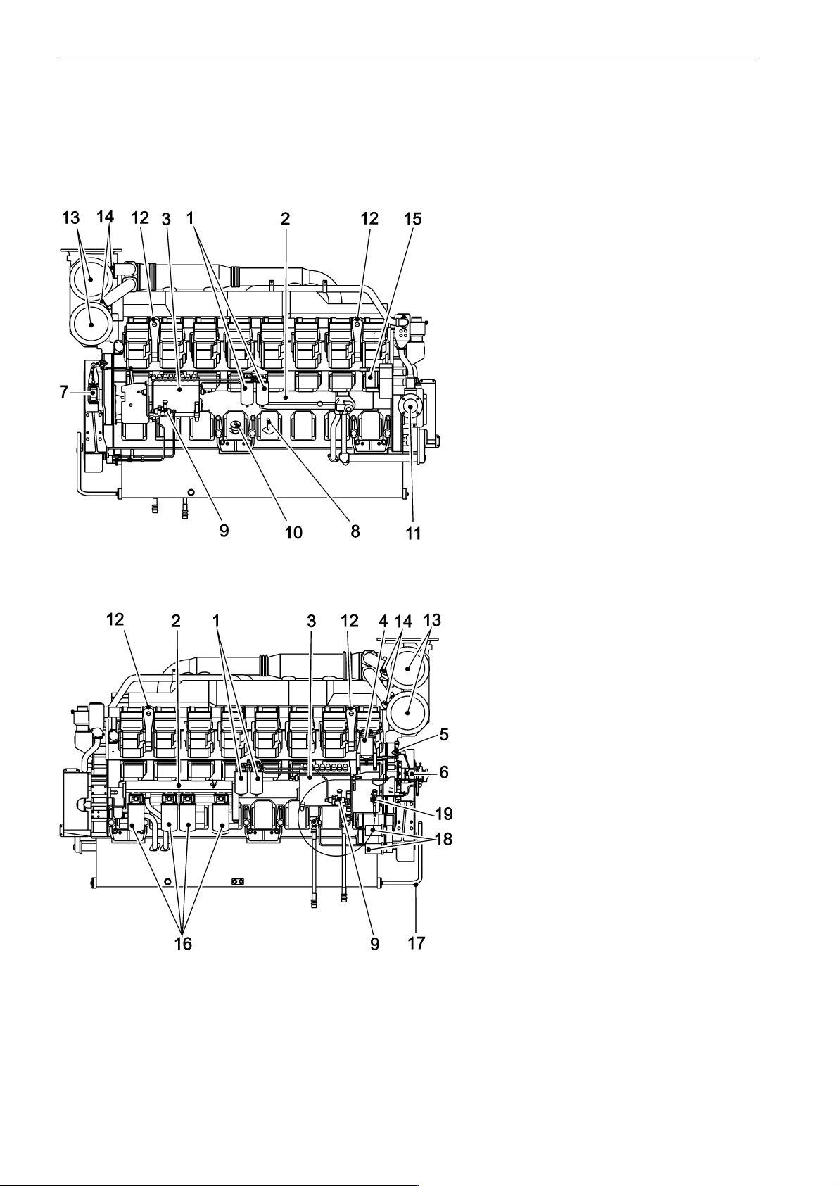
Presentation D65A MS
D65A MS
1. Fuel filters
2. Oil cooler
3. Fuel injection pump
4. Governor oil filter
5. Manual stop lever
6. Governor
7. Stop solenoid
8. Oil dipstick
9. Fuel feed pump
10. Oil filler cap
11. Fresh water pump
12. Lifting eye
13. Intake air silencer
14. Turbocharger
15. Alternator
16. Oil filters
17. Engine oil drain pipe
18. Starter motor
19. Manual speed control knob
16
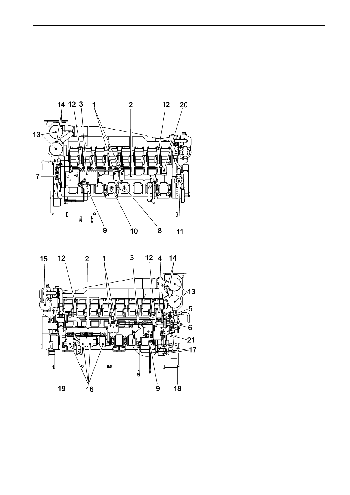
Presentation D65A MT
Plus d'informations sur : www.dbmoteurs.fr
D65A MT
1. Fuel filters
2. Oil cooler
3. Fuel injection pump
4. Governor oil filter
5. Manual stop lever
6. Governor
General information
7. Stop solenoid
8. Oil dipstick
9. Fuel feed pump
10. Oil filler cap
11. Fresh water pump
12. Lifting eye
13. Intake air silencer
14. Turbocharger
15. Heat exchanger
16. Oil filters
17. Starter motor
18. Engine oil drain pipe
19. Sea water pump
20. Alternator
21. Manual speed control knob
17
General information
Plus d'informations sur : www.dbmoteurs.fr
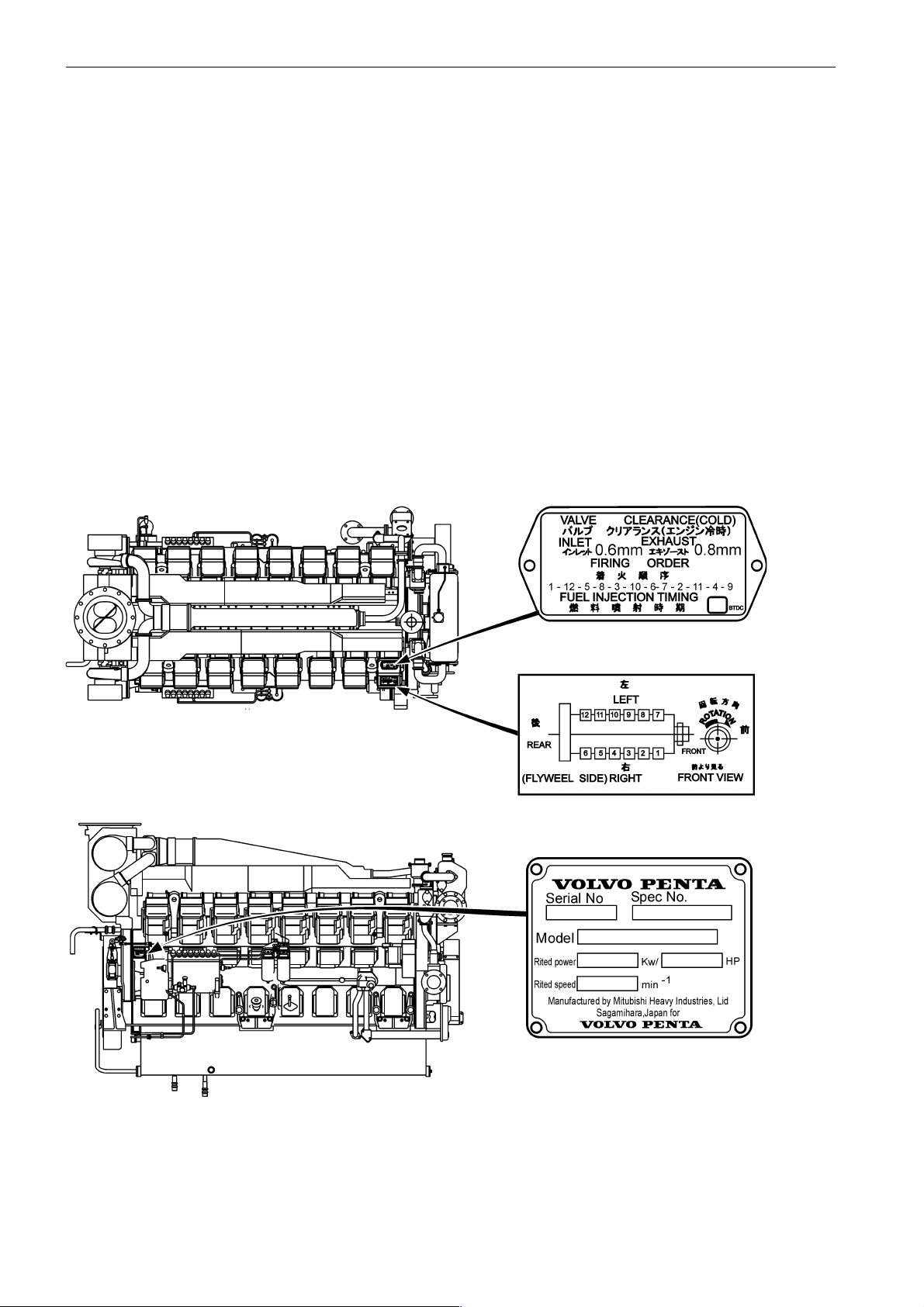
Identification numbers D65A
Type plates with identification numbers can be found on the engine and the transmission or generator. This information must always be used as a reference when ordering service and spare parts.
Engine ........................................................................................................................................
Product designation ....................................................................................................................
Serial and basic engine number .................................................................................................
Product number ..........................................................................................................................
Certification, IMO ........................................................................................................................
Decal, part No. ...........................................................................................................................
Approval No. ...............................................................................................................................
Transmission / Generator ...........................................................................................................
Product designation ....................................................................................................................
Serial number .............................................................................................................................
Product number ..........................................................................................................................
18

Specifications
Plus d'informations sur : www.dbmoteurs.fr
Specification D65A MS & MT
General specification
Model ........................................................................... Water-cooled,4-stroke, turbocharged diesel with air-cooled intercooler
No. of cylinders ............................................................. 16
Arrangement ................................................................. vertical V type
Combustion type ........................................................... Direct injection
Valve mechanism .......................................................... Overhead
Cylinder bore,mm [in.] ................................................... 170[6.70]
Cylinder stroke,mm [in.] ................................................ 180 [7.10]
Displacement, litres [U.S. gal] ........................................ 65.37 [17.27]
Compression ratio ......................................................... 14.0:1
Firing order ................................................................... 1-9-6-14-2-10-4-12-8-16-3-11-7-15-5-13
Rotational direction ........................................................ Counterclockwise as viewed from flywheel
Weight (Dry)(without marine gear), kg [lb] ..................... MS: 6220[13713] MT: 6400 [14112]
Engine main parts
Cylinder liner type ........................................................ Wet type
Piston rings:
Compression rings, pcs ............................................... 2
Oil ring(w/expander), pcs ............................................. 1
Valve timing (when warm):
Inlet valve ..................................................................... open BTDC 37°
Inlet valve ..................................................................... close ABDC 44°
Exhaust valve .............................................................. open BBDC 57°
Exhaust valve .............................................................. close ATDC 24°
Engine support method ................................................ 4 point support
Fuel system
Fuel
JIS K2204 .................................................................... TYPE 1, TYPE 2, TYPE 3
ASTM. D975 ................................................................ No.1-D, No.2-D
BS2869 ........................................................................ CLASS-A1, CLASS-A2,
DIN51601 ..................................................................... DIESEL-FUEL
ISO8217 ....................................................................... DMX-CLASS
Injection pump
Model ........................................................................... PS6 type
Manufacturer ................................................................ Mitsubishi Heavy Industries, Ltd.
Plunger outside diam., mm [in.] ................................... 17 [0.67]
Plunger lead, mm [in.] .................................................. Counterclockwise, left-hand 35 [1.38] lead
Cam lift, mm [in.] .......................................................... 15 [0.59]
Fuel feed pump
Model ........................................................................... Zexel
Manufacturer ................................................................ Zexel
Cam lift, mm [in.] .......................................................... 12 [0.47]
Governor
Control system ............................................................. Woodward Hydraulic PSG
19

Specifications
Plus d'informations sur : www.dbmoteurs.fr
Fuel system cont.
Fuel injector
Type ............................................................................. Hole type
Manufacturer ................................................................ Zexel
No. of spray holes ......................................................... 10
Spray hole diameter, mm [in.] ........................................ 0.325 [0.013]
Spray angle, deg. .......................................................... 160°
Injection press., Mpa(kgf/cm²)[psi] ................................ 34.32 to 34.81 (350 to 355) [4979 to 5050]
Fuel filter
Type ............................................................................. Paper element cartridge changeover, spin-on type
Oil system
Lubricating type ........................................................... Forced circulation type (pressure feed by oil pump)
Engine oil Standard ...................................................... CF oil (API service classification)
Engine oil volume:
Oil sump,liter [U.S. gal] ................................................ 200 [52.8] approx
Complete engine, liter [U.S. gal] .................................. 230 [60.8] approx
Oil pump
Type ............................................................................. Gear pump
Delivery capacity, liter [U.S. gal] .................................. 240 [63.4] (at engine speed 800 rpm)
Relief valve
Type ............................................................................. Piston valve type
Opening press., MPa(kgf/cm³)[psi] .............................. 0.51 +/-0.02 (5.2 +/-0.2) [73.97+/-2.84}
Oil cooler
Type ............................................................................. Water-cooled, multi-plate type (housed in the crankcase)
Full-flow oil filter
Type ............................................................................. Paper element changeover type (spin on)
Oil thermostat
Type ............................................................................. Wax type
Valve opening temp., °C [°F] ....................................... 80 to 84 [176 to 183.2]
Cooling system
Cooling type ................................................................. Water-cooled, forced circulation
Coolant capacity (whole engine), liter [U.S. gal] ............. MS: 170 [44.9] MT: 280 [74.0]
Fresh water pump
Type ............................................................................. Centrifugal
Pump capacity, liter [U.S. gal]/min. ................................ 1600 [423], Total head 0.20 MPa (20 mAq) (at 3292 rpm pump speed)
Thermostat
Type ............................................................................. Wax
Valve opening temp.,°C [°F] ........................................... 71+/-2 [159.8 +/- 3.6]
Raw water pump (only on MT)
Type ............................................................................. Rubber rotor
Pump capacity, liter [U.S. gal]/min. ................................ 800 [211], Total head 0.10 MPa (10 mAq)(at 1600 rpm pump speed)
Pump drive belt type ..................................................... V-belt
Outside circumference, mm [in] ..................................... 2085 [82] or 2115 [83]
20

Inlet and exhaust system
Plus d'informations sur : www.dbmoteurs.fr
Turbocharger
Type ............................................................................. MS: TD10 or TD13 MT: TD10 or TD13
No. of units .................................................................... 2
Electrical system
Voltage-polarity ............................................................. 24V earth float
Starter
Manufacturer ................................................................ Nikko Electric Industry
Pinion mesh type ........................................................... Pinion shift (Reduction type)
Output ........................................................................... V (kW) 24 (7.5)
No. of starters ............................................................... 2
No. of pinion tooth/ring gear tooth .................................. 15 / 182
Alternator
Type ............................................................................. 3-Phase alternating generator, Internal IC regulator
Manufacturer ................................................................ Mitsubishi Electric
Output ........................................................................... V-A 24-35
Rated generated ........................................................... min-1 5000 (at 27V, 35A)
Regulated voltrage ........................................................ V 28.5 +/- 0.5
Drive belt type ............................................................... V-belt
Outside circumference, mm [in.] .................................... 1000 [39.4]
Specifications
21

Maintenance Standards
Plus d'informations sur : www.dbmoteurs.fr
Maintenance Standards Table
General
Max
imum rpm
Nominal Value ....... 5 – 10 % higher than rated rpm
Repair limit ............ Lower or 20 % higher than rated rpm
NOTE! Rated rpm stamped on the nameplate. Check governor setting.
Minimum rpm
Nominal value ....... 600 to 650 rpm
Compression pressure MPa (Bar) [psi]
Nominal Value ....... 2.85 (28.5) [263] minimum (at 120 rpm)
Repair limit ............ 2.30 (23.0) [185] or lower
NOTE! Oil and water temp. 20 to 30°C [68 to 86°F]
Lube oil pressure MPa (Bar) [psi]
Nominal Value ....... 0.20 – 0.29 (2.0 – 2.9) [28 to 43] at idling
Repair limit ............ 0.10 (1.0) [14] or lower
NOTE! Oil temp. 60 to 70°C [140 to 158°F]
Valve timing (2 mm[0.8 in.] clearance valve side, cold)
Nominal Value:
Inlet valve opens ... 2.5° BTDC ±2° (crank angle)
Inlet valve closes .. 13° ABDC ±2° (crank angle)
Exh. valve opens .. 26° BBDC ±2° (crank angle)
Exh. valve closes . 10.5° BTDC ±2° (crank angle)
NOTE! Values are only for checking valve timing and are different from the actual ones.
Valve clearance (cold), mm [in.]
Inlet valves:
Standard Clearance 0.6 [0.024]
Exhaust valves:
Standard Clearance 0.8 [0.031]
Injection timing
Nominal Value ....... XX° BTDC ±1° (crank angle)
NOTE! XX varies according to specifications. Refer to caution plate on No. 1 rocker cover.
Engine main parts
Valves
Valve stem diameter, mm [in.]
Nominal Value ....... Ø10 [0.39]
Assembly Standard 9.940 to 9.960 [0.39134 to 0.39213]
Service Limit ......... 9.910 [0.39016]
NOTE! The same for both inlet and exhaust valves.
22
Valve guide inside diameter, mm [in.]
Plus d'informations sur : www.dbmoteurs.fr
Nominal Value ........... Ø10 [0.39]
Assembly Standard ... 10.000 to 10.015 [0.39370 to 0.39429]
Service Limit ............. 10.060 [0.39606]
NOTE! The same for both inlet and exhaust valves.
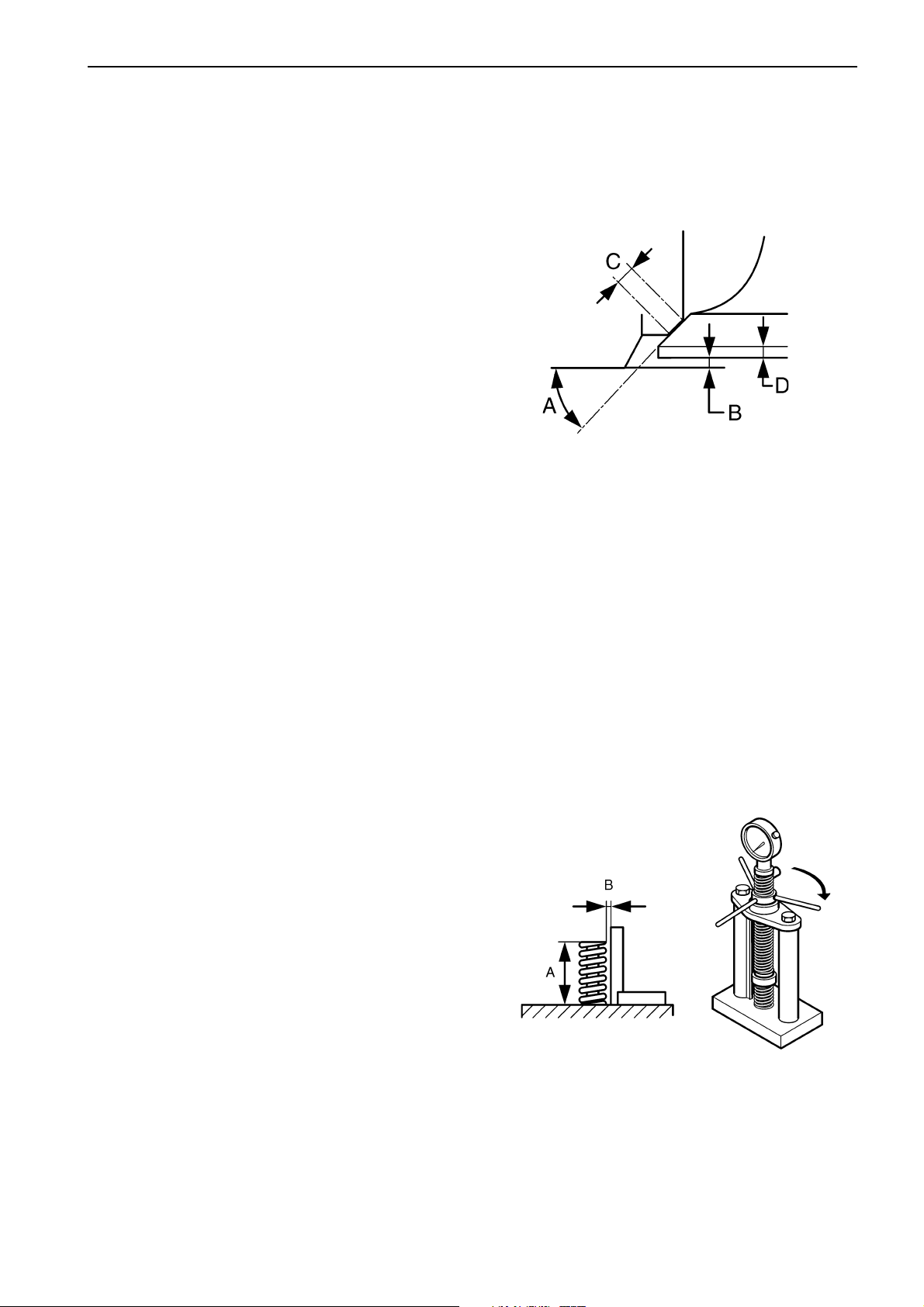
Valve seat angle(A)
Nominal Value ........... 30°
Valve depth(B), mm [in.]
Nominal value ........... 0
Assembly Standard ... -2.0 – 0.2 [-0.008 – 0.008]
Repair Limit ............... 1.0 [0.039]
Seat width(C), mm [in.]
Nominal value ........... 2.3 [0.091]
Assembly Standard ... 2.15 to 2.45 [0.0846 to 0.0965]
Repair Limit ............... 2.8 [0.110]
Valve margin(D), mm [in.]
Nominal Value ........... 3.0 [0.12]
Assembly Standard ... 2.8 – 3.2 [0.110 to 0.126]
NOTE! Refacing permissible up to 2.5 [0.098]
Maintenance Standards
Cylinder head bore and valve seat diameter, mm [in.]
Nominal Value ........... Ø60 [2.36]
Assembly Standard ... -0.070 – -0.130 [-0.00276 – -0.00512]
NOTE! - (minus) indicates interference
Valve push rods
Deflection, mm [in.]
Assembly Standard ... 0.5 [0.020] maximum
Service Limit ............. 0.5 [0.020]
Valve springs
Free length (A), mm [in.]
Assembly standard ... 73 [2.87]
Service limit .............. 71 [2.80]
Perpendicularity (B), mm [in.]
Service limit .............. 2.2 [0.087] (at end)
Length under test force, mm [in.]
Assembly standard ... 66.0 [2.6]
Test force, N (kgf) [lbf]
Assembly standard ... 289–319 (29.45 to 32.55) [65 to 72]
23

Maintenance Standards
Plus d'informations sur : www.dbmoteurs.fr
Rockers
Rocker bushing inside diameter, mm [in.]
Nominal Value ........... Ø36 [1.42]
Assembly Standard ... 36.000 to 36.040 [1.41732 to 1.41889]
Service Limit ............. 36.090 [1.42086]
Rocker shaft diameter, mm [in.]
Nominal Value ........... Ø36 [1.42]
Assembly Standard ... 35.966 to 35.991 [1.41598 to 1.41697
Service Limit ............. 35.940 [1.41496]Cylinder heads
Flatness of gasket surface, mm [in.]
Assembly Standard ... 0.03 [0.0012] or less
Repair Limit ............... 0.07 [0.0028]
Service Limit ............. 0.50 [0.0197]
NOTE! Reface if necessary
Thickness of gasket when tightened, mm [in.]
Nominal Value ........... 1.8 [0.07]
Assembly Standard ... 1.77 to 1.83 [0.0697 to 0.0720]
Cylinder liners
Inside diameter, mm [in.]
Nominal Value ........... Ø170 [6.69]
Assembly Standard ... 170.000 to 170.040 [6.69290 to 6.69447]
Repair Limit ............... 170.200 [6.70078]
Service Limit ............. 170.500 [6.71259]
Roundness, mm [in.]
Assembly Standard ... 0.02 [0.0008] or less
Cylindricity, mm [in.]
Assembly Standard ... 0.02 [0.0008] or less
Squareness of flange lower face to liner center line, mm [in.]
Assembly Standard ... 0.03 [0.0012] or less
Protrusion of cylinder liner at flange, mm [in.]
Assembly Standard ... 0.11 to 0.20 [0.0043 to 0.0089]
Pistons and cylinderheads
Clearance between piston top and cylinder head, mm [in.]
Standard Clearance .. [1.22 to 1.95) ([0.0480 to 0.0768])
Pistons
Outside diameter, mm [in.]
Nominal Value ........... Ø170 [6.69]
Assembly Standard ... 169.76 to 169.80 [6.6835 to 6.6850]
Service Limit ............. 169.66 [6.6795]
NOTE! Meaure diameter perpendicular to pin at piston skirt.
24

Weight difference between pistons in one engine
Plus d'informations sur : www.dbmoteurs.fr
Assembly Standard ... ±10 g [±0.35 oz]
Pin bore diameter, mm [in.]
Nominal Value ........... Ø70 [2.76]
Assembly Standard ... 70.002 to 70.015 [2.75598 to 2.75649]
Service Limit ............. 70.040 [2.75747]
Protrusion, mm [in.]
Assembly Standard ... 0.06 to 0.65 [0.0024 to 0.0256]
NOTE! From the cylinder block
Piston rings
Gaps Top ring, mm [in.]
Assembly Standard ... (0.6 to 0.8) ([0.024 to 0.031])
Service Limit ............. (2.0) ([0.079])
NOTE! If gauge is not available, the general value can be obtained at the cylinder bore.
Gaps Second ring, mm [in.]
Assembly Standard ... (0.6 to 0.8) ([0.024 to 0.031])
Service Limit ............. (2.0) ([0.079])
NOTE! If gauge is not available, the general value can be obtained at the cylinder bore.
Maintenance Standards
Gaps Oil ring, mm [in.]
Assembly Standard ... (0.3 to 0.45) ([0.012 to 0.018])
Service Limit ............. (2.0) ([0.079])
NOTE! If gauge is not available, the general value can be obtained at the cylinder bore.
Piston pins
Diameter, mm [in.]
Nominal Value ........... Ø70 [2.76]
Assembly Standard ... 69.987 to 70.000 [2.75539 to 2.75590]
Service Limit ............. 69.970 [2.75472]
Connecting rods
Bushing inside diameter, mm [in.]
Nominal Value ........... Ø70 [2.76]
Assembly Standard ... 70.020 to 70.040 [2.75669 to 2.75747]
Service Limit ............. 70.070 [2.75866]
Bend and twist, mm [in.]
Assembly Standard ... 0.05/100 [0.0020/3.9] or less
End play (rod and crankpin widths), mm [in.]
Nominal Value ........... 60 [2.36] x 2
Assembly Standard ... (0.4 to 0.9) ([0.016 to 0.035])
Service Limit ............. (1.4) ([0.055])
Weight difference between connecting rods in one engine
Assembly Standard ... ±30 g [±1.06 oz]
25

Maintenance Standards
Plus d'informations sur : www.dbmoteurs.fr
Big end bore diameter, mm [in.]
Nominal Value ........... Ø131 [5.16]
Assembly Standard ... 131.000 to 131.025 [5.15747 to 5.15845]
Service Limit ............. 131.050 [5.15944]
NOTE! To be measured in combination with caps. Roundness less than (0.1 mm [0.004 in.] - service limit)
Connecting rod bearings
Thickness of center, STD, mm [in.]
Nominal Value ........... 3.000 [0.11811]
Assembly Standard ... 2.972 to 2.985 [0.11701 to 0.11752]
Service Limit* ............ 2.930 [0.11535]
Thickness of center, –0.25 [–0.0098], mm [in.]
Nominal Value ........... 3.125 [0.12303]
Assembly Standard ... 3.097 to 3.110 [0.12193 to 0.12244]
Service Limit* ............ 3.055 [0.12028]
Thickness of center, –0.50 [–0.0197], mm [in.]
Nominal Value ........... 3.250 [0.12795]
Assembly Standard ... 3.222 to 3.235 [0.12685 to 0.12736]
Service Limit* ............ 3.180 [0.12520]
Thickness of center, –0.75 [–0.0295], mm [in.]
Nominal Value ............ 3.375 [0.13287]
Assembly Standard ... 3.347 to 3.360 [0.13177 to 0.13228]
Service Limit* ............ 3.305 [0.13012]
Thickness of center, –1.00 [–0.0394], mm [in.]
Nominal Value ........... 3.500 [0.13780]
Assembly Standard ... 3.472 to 3.485 [0.13669 to 0.13720]
Service Limit ............. 3.430 [0.13504]
*NOTE! Replace bearings if worn down to service limit. Regrind crankpins and use undersize bearings if necessary.
Oil pump drive
Cover bearing journal inside diameter, mm [in.]
Nominal Value ........... Ø110 [4.33]
Assembly Standard ... 110.000 to 110.035 [4.33070 to 4.33208]
Plate bearing journal inside diameter, mm [in.]
Nominal Value ........... Ø110 [4.33]
Assembly Standard ... 109.987 to 110.022 [4.33019 to 4.33157]
Bearing, Outside diameter, mm [in.]
Nominal Value ........... Ø110 [4.33]
Assembly Standard ... 109.985 to 110.000 [4.33012 to 4.33071]
Bearing, Inside diameter, mm [in.]
Nominal Value ........... Ø50 [1.97]
Assembly Standard ... 49.988 to 50.000 [1.96803 to 1.96850]
Gear shaft bearing journal diameter, mm [in.]
Nominal Value ........... Ø50 [1.97]
Assembly Standard ... 49.993 to 50.013 [1.96822 to 1.96901]
26

Flywheel
Plus d'informations sur : www.dbmoteurs.fr
Face runout, mm [in.]
Assembly Standard ... 0.336 [0.0132] to less
Radial runout, mm [in.]
Assembly Standard ... 0.13 [0.0051] or less
Injection pump accessory drive
Bearing bore inside diameter, mm [in.]
Nominal Value ........... Ø90 [3.54]
Assembly Standard ... 89.987 – 90.022 [3.54279 – 3.54417]
Bearing bore inside diameter, mm [in.]
Nominal Value ........... Ø100 [3.94]
Assembly Standard ... 99.987– 100.022 [3.93649 – 3.93787]
Bearing, Outside diameter, mm [in.]
Nominal Value ........... Ø90 [3.54]
Assembly Standard ... 89.985 – 90.000 [3.54272 – 3.54331]
Maintenance Standards
Bearing, Outside diameter, mm [in.]
Nominal Value ........... Ø100 [3.94]
Assembly Standard ... 99.985 – 100.000 [3.93642 – 3.93701]
Bearing, Inside diameter, mm [in.]
Nominal Value ........... Ø45 [1.77]
Assembly Standard ... 44.988 to 45.000 [1.77118 to 1.77165]
Bearing, Inside diameter , mm [in.]
Nominal Value ........... Ø50 [1.97]
Assembly Standard ... 49.988 to 50.000 [1.96803 to 1.96850]
Drive shaft bearing journal diameter, mm [in.]
Nominal Value ........... Ø45 [1.77]
Assembly Standard ... 45.002 to 45.013 [1.77173 to 1.77216]
Drive shaft bearing journal diameter, mm [in.]
Nominal Value ........... Ø50 [1.97]
Assembly Standard ... 50.002 to 50.013 [1.96858 to 1.96901]
Damper
Radial runout (at periphery), mm [in.]
Assembly Standard ... 0.5 [0.020] or less
Service Limit .............. 1.5 [0.059]
Face runout, mm [in.]
Assembly Standard .... 0.5 [0.020] or less
Service Limit ............. 1.5 [0.059]
27

Maintenance Standards
Plus d'informations sur : www.dbmoteurs.fr
Front gears
Backlash, mm [in.]
Assembly Standard ... (0.12 to 0.18) ([0.0047 to 0.0071])
Repair Limit ............... (0.30) ([0.0118])
Service Limit ............. (0.50) ([0.0197])
NOTE! Replace gears, if necessary
Idle gear shaft bushing inside diameter, mm [in.]
Nominal Value ........... Ø50 [1.97]
Assembly Standard ... 50.000 to 50.025 [1.96850 to 1.96948]
Service Limit ............. 50.060 [1.97086]
Idle gear shaft diameter, mm [in.]
Nominal Value ........... Ø50 [1.97]
Assembly Standard ... 49.950 to 49.975 [1.966553 to 1.96752]
Service Limit ............. 49.900 [1.96456]
Idle gear end play, mm [in.]
Assembly Standard ... (0.2 to 0.4) ([0.008 to 0.016])
Service Limit ............. (0.6) ([0.024])
Timing gears
Backlash, mm [in.]
Assembly Standard ... (0.12 to 0.18) ([0.0047 to 0.0071])
Repair Limit ............... (0.30) ([0.0118])
Service Limit ............. (0.50) ([0.0197])
Idle gear shaft bushing inside diameter, mm [in.]
Nominal Value ........... Ø65 [2.56]
Assembly Standard ... 65.000 to 65.030 [2.55906 to 2.56024]
Service Limit ............. 65.060 [2.56142]
Idle gear shaft diameter, mm [in.]
Nominal Value ........... Ø65 [2.56]
Assembly Standard ... 64.951 to 64.970 [2.55713 to 2.55787]
Service Limit ............. 64.900 [2.55512]
Idle gear end play, mm [in.]
Assembly Standard ... (0.3 to 0.6) ([0.118 to 0.236])
Service Limit ............. (1.0) ([0.0397])
28

Camshaft
Plus d'informations sur : www.dbmoteurs.fr
Cam lift (A-B), mm [in.]
Nominal Value ........... 9.247 [0.36405]
Assembly Standard ... 9.197 to 9.297 [0.36209 to 0.36602]
Service Limit ............. 8.45 [0.3327]
Deflection, mm [in.]
Assembly Standard ... 0.05 [0.0020] or less
Repair Limit ............... 0.08 [0.0031]
NOTE! Deflection at center bushing measured with both ends supported. Repair or replace, if necessary.
Journal diameter, mm [in.]
Nominal Value ........... Ø84 [3.31]
Assembly Standard ... 83.92 to 83.94 [3.3039 to 3.3047]
Service Limit ............. 83.87 [3.3020]
Camshaft bushing inside diameter (as installed in crank case), mm [in.]
Nominal Value ........... Ø84 [3.31]
Assembly Standard ... 84.00 to 84.035 [3.30708 to 3.30846]
Service Limit ............. 84.10 [3.3110]
NOTE! Replace bushings and ream them, if necessary
Maintenance Standards
End play, mm [in.]
Nominal Value ........... 8 [0.3]
Assembly Standard ... 0.10 to 0.25 [0.0039 to 0.0098]
Service Limit ............. 0.40 [0.0157])
NOTE! Replace thrust bearing, if necessary.
Crankshaft
Crankpin diameter, mm [in.]
Nominal Value ........... Ø125 [4.92]
Assembly Standard ... -0.050 – -0.070 [0.00197 – -0.00276]
Repair Limit ............... -0.110 [-0.00433]
Crankpin journal diameter, mm [in.]
Nominal Value ........... Ø170 [6.69]
Assembly Standard ... -0.060 – -0.080 [0.00236 – -0.00315]
Repair Limit ............... -0.110 [-0.00433]
Journal and crankpin center to center distance, mm [in.]
Nominal Value ........... 90 [3.54]
Assembly Standard ... ±0.1 [±0.004]
Parallelism between journals and crankpins, mm [in.]
Assembly Standard ... 0.01 [0.0004] or less at pin length
Repair Limit ............... 0.03 [0.0012]
Roundness of journals and crankpins, mm [in.]
Assembly Standard ... 0.01 [0.0004] or less in diameters
Repair Limit ............... 0.03 [0.0012]
Cylindricity of journals and crankpins, mm [in.]
Assembly Standard ... 0.02 [0.0008] or less in diameters
Repair Limit ............... 0.03 [0.0012]
29

Maintenance Standards
Plus d'informations sur : www.dbmoteurs.fr
Fillet radius of crankpins, mm [in.]
Nominal Value ........... 7 [0.28]
Assembly Standard ... 7.0 – 7.2
[0.268 – 0.276]
Fillet radius of journals, mm [in.]S
Nominal Value ........... 8.5 [0.33]
Assembly Standard ... 8.3 – 8.5
[0.327 – 0.335]
Hardness of journals and crankpins
Assembly Standard .... Hv>590
Angularity
Assembly Standard ... ±0°20’
Deflection, mm [in.]
Assembly Standard ... 0.04 [0.0016] or less
Repair Limit ............... 0.10 [0.0039]
NOTE! Repair or replace if necessary
Crankshaft end play, mm [in.]
Nominal Value ........... 67 [2.64]
Assembly Standard ... 0.20 to 0.40 [0.0079 to 0.0157]
Service Limit .............. 0.50 [0.0197] + 1.18[0.0465] (crank shaft width)
NOTE! Replace thrust bearings if worn down to service limit. Use oversize thrust bearings if worn beyond repair limit.
Main bearing
Thickness of center, STD, mm [in.]
Nominal Value ........... 4.500 [0.17717]
Assembly Standard ... 4.467 to 4.480 [0.17587 to 0.17638]
Service Limit ............. 4.425 [0.17421]
NOTE! Replace bearings if worn down to service limit. Regrind crankpins and use undersize bearings if worn beyond service limit.
Thickness of center, –0.25 [–0.0098], mm [in.]
Nominal Value ........... 4.625 [0.18209]
Assembly Standard ... 4.592 to 4.605 [0.18079 to 0.18130]
Service Limit ............. 4.550 [0.17913]
NOTE! Replace bearings if worn down to service limit. Regrind crankpins and use undersize bearings if worn beyond service limit.
Thickness of center, –0.50 [–0.0197], mm [in.]
Nominal Value ........... 4.750 [0.18701]
Assembly Standard ... 4.717 to 4.730 [0.18571 to 0.18622]
Service Limit ............. 4.675 [0.18405]
NOTE! Replace bearings if worn down to service limit. Regrind crankpins and use undersize bearings if worn beyond service limit.
Thickness of center, –0.75 [–0.0295], mm [in.]
Nominal Value ........... 4.875 [0.19193]
Assembly Standard ... 4.842 to 4.855 [0.19063 to 0.19114]
Service Limit ............. 4.800 [0.18898]
NOTE! Replace bearings if worn down to service limit. Regrind crankpins and use undersize bearings if worn beyond service limit.
Thickness of center, –1.00 [–0.0394], mm [in.]
Nominal Value ........... 5.000 [0.19685]
Assembly Standard ... 4.967 to 4.980 [0.19555 to 0.19606]
Service Limit ............. 4.925 [0.19390]
NOTE! Replace bearings if worn down to service limit. Regrind crankpins and use undersize bearings if worn beyond service limit.
30
 Loading...