

Volvo Penta IPS, IPS 350, IPS 400, IPS 450, IPS 500 Operator's Manual
...
OPERATOR’S MANUAL
Volvo Penta IPS

An English version of this Operator’s Manual may
be ordered free of charge up to 12 months after delivery, via
internet, mail or fax. Refer to the order form in the back of
the book.
All information is stored internally at AB Volvo Penta and will
not be passed on to third parties.
Diese deutsche Version dieses Handbuches kann
innerhalb von 12 Montane ab Lieferung kostenlos online,
per Brief oder per Fax bestellt werden. Bitte Bestellformular
hinten im Buch verwenden.
Alle Angaben werden bei AB Volvo Penta gespeichert und
nicht Dritten übermittelt.
Une version française de ce manuel d’instructions
peut être commandée gratuitement, jusqu’à 12 mois après
la date de livraison, via Internet, la poste ou par fax. Voir à
la n de ce document.
Toutes les informations sont stockées en interne chez AB
Volvo Penta et ne sont divulguées à aucun tiers.
Hay disponible una versión en español gratuita de
este manual de instrucciones, la cual puede pedirse, a través de Internet, correo postal o fax, en el plazo de 12 meses
después de la entrega del producto. Véase el formulario de
pedido en las últimas páginas del manual.
Todos los datos recibidos son almacenados de forma in-
En svensk version av denna instruktionsbok kan
beställas kostnadsfritt, upp till 12 månader efter leverans,
via internet, post eller fax. Se beställningsformulär i slutet av
boken.
Alla uppgifter lagras internt hos AB Volvo Penta och lämnas
inte ut till tredje part.
Een Nederlandse versie van dit instructieboek kan
kosteloos worden besteld tot 12 maanden na aevering, internet, post of fax. Zie het bestelformulier achterin het boek.
Alle gegevens worden intern opgeslagen bij AB Volvo Penta
en niet verstrekt aan derden.
En dansk version af denne instruktionsbog kan
bestilles gratis, op til 12 måneder efter levering, via internet,
post eller telefax. Se bestillingsformular i slutningen af bogen.
Alle oplysninger gemmes internt hos AB Volvo Penta og
overgives ikke til tredje part.
Tämän ohjekirjan suomenkielisen version voi tilata
veloituksetta 12 kuukauden sisällä toimituksesta internetistä,
postin kautta tai faksilla. Katso tilauslomake kirjan lopusta.
AB Volvo Penta tallentaa kaikki tiedot sisäisesti eikä niitä
luovuteta kolmannelle osapuolelle.
Pode-se encomendar uma versão gratuita deste
manual de instruções em português, até 12 meses após a
entrega, através de Internet, correio ou fax. Consultar o for-
mulário de encomenda no m do manual.
Todas as informações são armazenadas internamente pela
Volvo Penta e não são partilhadas com terceiros.
Εντός 12 μηνών από την παράδοση μπορείτε να
παραγγείλετε μέσω Internet, ταχυδρομικής επιστολής ή φαξ
μια ελληνική έκδοση του Βιβλίου χρήσης χωρίς χρέωση.
Χρησιμοποιήστε το δελτίο παραγγελίας στο τέλος του
βιβλίου.
Όλες οι πληροφορίες αποθηκεύονται από την AB Volvo Pen-
Вариант настоящего руководства по
эксплуатации на русском языке можно заказать
бесплатно в течение 12 месяцев после доставки по
Интернету, электронной почте или по факсу. См. бланк
заказа на обложке руководства.
Вся информация используется компанией AB Volvo Penta конфиденциально и не передается третьим сторонам.
Bu Kullanım Kılavuzunun Türkçe versiyonu teslim-
den 12 ay sonrasına kadar internet, posta veya faks yoluya
sipariş edilebilir. Kitabın arka kısmında bulunan sipariş formuna bakınız.
Tüm bilgiler AB Volvo Penta’da saklıdır ve üçüncü kişilere
verilmez.
Una versione in lingua italiana di questo manuale di
istruzioni può essere ordinata gratuitamente, no a 12 mesi
dopo la consegna, via internet, per posta o via fax. Vedere il
modulo per l’ordinazione alla ne del manuale.
Tutti i dati forniti saranno memorizzati internamente presso
AB Volvo Penta e non saranno divulgati a terzi.
CALIFORNIA
Proposition 65 Warning
Diesel engine exhaust and some of its constituents are known
to the State of California to cause cancer, birth defects, and
other reproductive harm.

Content
Foreword ...................................................................................................... 2
Safety Information ...................................................................................... 3
Introduction ................................................................................................. 8
Presentation .............................................................................................. 10
Instruments and Controls ........................................................................ 12
Optional ..................................................................................................... 26
Starting ...................................................................................................... 31
Operation ................................................................................................... 34
Engine Shutdown ...................................................................................... 38
Fault Handling ........................................................................................... 41
Fault Code Register .................................................................................. 45
In Case of Emergency .............................................................................. 57
Maintenance Schedule ............................................................................. 65
Maintenance .............................................................................................. 67
Storage ....................................................................................................... 98
Calibration and Settings ......................................................................... 102
Technical Data ......................................................................................... 114
Alphabetical index .................................................................................. 120
1

Foreword
Volvo Penta marine engines are used all over the world. They are used in all possible operating conditions for
professional as well as leisure purposes. This is not a coincidence. After 100 years as an engine manufacturer
the Volvo Penta name has become a symbol of reliability, technical innovation, top of the range performance and
long service life. We also believe that this is what you demand and expect of your Volvo Penta engine.
We would like you to read this operator’s manual thoroughly and consider the advice we give on running and
maintenance before your maiden voyage so that you will be ensured of fulfilling your expectations. Please pay
attention to the safety instructions contained in the manual.
As owner of a Volvo Penta marine engine, we would also like to welcome you to a worldwide network of dealers
and service workshops to assist you with technical advice, service requirements and replacement parts. Please
contact your nearest authorized Volvo Penta dealer for assistance.
You will find your closest dealer at our home page on the Internet www.volvopenta.com - amongst other
useful information about your Volvo Penta engine - we invite you to visit!
2 7748921 04-2008
Safety Information
Read this chapter very carefully. It has to do with your safety. This describes how safety information is presented
in the instruction book and on the product. It also gives you an introduction to the basic safety rules for using and
looking after the engine.
Check that you heave received the correct instruction book before you read on. If not, please contact your
Volvo Penta dealer.
!
This symbol is used in the instruction book and on the product, to call your attention to
the fact that this is safety information. Always read such information very carefully.
Safety texts in the instruction book have the following order of priority:
DANGER!
Indicates a hazardous situation which, if not avoided, will result in death or serious
injury.
WARNING!
Indicates a hazardous situation which, if not avoided, could result in death or serious
personal injury.
CAUTION!
Indicates a hazardous situation which, if not avoided, could result in minor or moderate
personal injury.
IMPORTANT!
Indicates a situation which, if not avoided, could result in property damage.
NOTICE! Used to draw attention to important information that will facilitate work or
operations.
This symbol is used on our products in some cases and refers to important information
in the instruction book. Make sure that warning and information symbols on the engine
are clearly visible and legible. Replace symbols which have been damaged or painted
over.
7748921 04-2008 3

Your new boat
Read the instruction books and other information
carefully, which came with your new boat. Learn to
handle the engine, controls and other equipment in a
safe and correct manner.
If this is your first boat, or a type of boat you are not
experienced in using, we recommend that you practice operating the boat in peace and quiet. Get to know
the way the boat reacts to sea and to the controls
under different speed, sea and loading conditions
before you cast off for your first “real” maiden voyage.
Remember that the captain of every boat is required
by law to know and to observe applicable rules for
traffic and safety at sea. Get to know the rules which
apply to you and your waters, by contacting the relevant authority or sea safety organization.
It is a good idea to go on some kind of boat operation
course. We recommend that you contact a regional
boat or sea safety organization to find a suitable
course.
Fuel filling
There is always a risk of fire and explosion during fuel
filling. Smoking is not permissible, and the engine
should be stopped.
Never over-fill the tank. Shut the tank cap securely.
Only use the fuel recommended in the instruction
book. The wrong grade of fuel can cause serious malfunctions, power loss or stop the engine.
Daily checks
Make it a habit to give the engine and engine bay a
visual check before driving (before starting the
engine) and after operation (when you have stopped
the engine). This helps you to quickly discover
whether any leakage of fuel, coolant, oil or any other
abnormal event has happened, or is about to happen.
Do not start the engine
Do not start the engine if you suspect a fuel or LPG
leak in the boat, close to explosive media, or if there
is a spillage of explosive media. An explosive environment entails a risk of fire and/or explosion.
Manoeuvring
Avoid sudden or surprising rudder movements and
gear shifting. There is a risk that passengers could fall
over, or overboard.
A rotating propeller can cause severe injury. Check
that there is nobody in the water before you engage
forward / astern (reverse) drive. Never drive close to
bathers or in areas where you could reasonably
expect that people could be in the water.
Accidents and near misses
Life saving statistics show that inadequate care of
boats and engines, and deficiencies in safety equipment are frequent causes of accidents and near
misses at sea.
Make sure that your boat and engine are maintained
in accordance with the advice in each instruction
book, and that the necessary safety equipment is on
board, and is in working condition.
Safety Information
4 7748921 04-2008

Carbon monoxide poisoning
When a boat moves forwards, an area of low pressure
air forms behind the boat. In adverse conditions, this
low pressure can be so strong that the boat’s own
exhaust fumes are sucked into the cockpit or cabin,
which entails a risk of carbon monoxide poisoning for
all aboard.
The problem of low-pressure suction is worst in high,
wide boats with a square transom. But even in other
types of boats, low-pressure suction can be a problem
in some conditions, such as if you drive with the hood
up. Other factors which increase the low-pressure
effect are wind conditions, load distribution, pitching,
trimming, open windows and ventilators etc.
Most modern boats are designed so that the problem
of low-pressure suction is very rare, however. If lowpressure suction does occur anyway, do not open
hatches or ventilators in the forward part of the boat.
Strangely enough, this makes the problem worse. Try
changing speed, trimming or load distribution instead.
Also try taking down/opening the hood or modifying it
in some other manner. Ask your boat dealer for advice
about the best solution for your particular boat.
P0003073
Remember
• Safety equipment: Life jackets for everybody aboard, communication equipment, emergency
rockets, approved fire extinguisher, first aid kit, life buoy, anchor, paddle, torches etc.
• Spare parts and tools: Impeller, fuel filters, fuses, tape, hose clamps, engine oil, propeller and
tools for the jobs you could be expected to have to do.
• Take your chart out and study your planned route. Calculate distance and fuel consumption.
Listen to weather reports.
• Tell your friends/relatives about route plans if you undertake a long journey. Remember to
notify changed plans or delays.
• Inform everybody aboard about where the safety equipment is located, and how it works. Make
sure that there is more than one person aboard who can start and operate the boat safely.
This list can be extended, since the need for safety equipment varies with the type of boat, and
where or how it is used etc. We recommend that you ask a regional boat or sea safety organization
for more detailed maritime safety information.
Safety Information
7748921 04-2008 5

Preparations
Knowledge
The operator’s manual contains instructions on how
to carry out general maintenance and service operations safely and correctly. Read the instructions carefully before starting work.
Service literature covering more complicated operations is available from your Volvo Penta dealer.
Never carry out any work on the engine if you are
unsure of how it should be done, contact your Volvo
Penta dealer who will be glad to offer assistance.
Stop the engine
Stop the engine before opening or removing engine
hatches. Unless otherwise specified all maintenance
and service must be carried out with the engine stopped.
To prevent accidental start of the boat engine, remove
the ignition key, turn off the power supply to the engine
at the main switches and lock them in the OFF position before starting work. Put up a warning sign in the
control position that work on the engine is being carried out.
Approaching or working on an engine which is running
is a safety risk. Loose clothing, hair, fingers or a dropped tool can be caught in the rotating parts of the
engine and cause serious personal injury. Volvo
Penta recommend that all servicing with the engine
running should be undertaken by an authorized Volvo
Penta workshop.
Lifting the engine
When lifting the engine, use the lifting eyes installed
on the engine. Always check that lifting equipment is
in good condition and has sufficient load capacity to
lift the engine (engine weight including any extra
equipment installed). For safety’s sake lift the engine
using an adjustable lifting beam. All chains and cables
should run parallel to each other and as perpendicular
as possible in relation to the top of the engine. Bear
in mind that extra equipment installed on the engine
may alter its center of gravity. Special lifting equipment may then be required in order to maintain the
correct balance and make the engine safe to handle.
Never carry out work on an engine suspended on a
hoist.
Before starting the engine
Reinstall all protective parts removed during service
operations before starting the engine. Check that no
tools or other items have been left on the engine.
Never start a turbocharged engine without installing
the air cleaner (ACL). The rotating compressor in the
Turbocharger unit can cause serious personal injury.
Foreign objects can also be sucked in and cause
mechanical damage to the unit.
Fire and explosion
Fuel and lubrication oil
All fuel, most lubricants and many chemicals are
inflammable. Read and follow the instructions on the
packaging.
When carrying out work on the fuel system, make sure
the engine is cold. A fuel spill onto a hot surface or
electrical components can cause a fire.
Store fuel soaked rags and other flammable material
so that there is no danger of them catching fire. Fuelsoaked rags can self-ignite under certain conditions.
Do not smoke when filling fuel, oil or in proximity of a
filling station or in the engine room.
Non-original components
Components used in the fuel and electrical systems
on Volvo Penta products are designed and constructed to minimize the risk of fire and explosion.
Using non-original Volvo Penta parts can result in fire
or explosion on board.
Batteries
The batteries contain and emit oxyhydrogen gas,
especially during charging. This gas is easily ignited
and highly volatile.
Do not under any circumstances smoke or use naked
flame or allow sparks in the vicinity of the batteries or
battery compartment.
An incorrect connection of a battery terminal cable or
jump-start cable can cause a spark which in its turn
can be sufficient to cause an explosion.
Start spray
Never use start spray or similar agents to start an
engine equipped with air pre-heating (glow plugs/
starter element). This may cause an explosion in the
inlet manifold. Danger of personal injury.
Safety Information
6 7748921 04-2008

Hot surfaces and fluids
There is always a risk of burns when working with a
hot engine. Beware of hot surfaces. For example: the
exhaust pipe, turbo unit, oil pan, charge air pipe,
starter element, hot coolant and hot oil in oil lines and
hoses.
Carbon monoxide poisoning
Only start the engine in a well-ventilated area. If operating the engine in an enclosed space, ensure that
there is proper ventilation in order to remove exhaust
gases and crankcase ventilation emissions from the
working area.
Chemicals
Most chemicals such as anti-freeze, rustproofing
agent, inhibiting oil, degreasing agent etc. are hazardous to health. Read and follow the instructions on
the packaging.
Some chemicals such as inhibiting oil are inflammable
and dangerous if breathed in as well. Ensure good
ventilation and use a protective mask when spraying.
Read and follow the instructions on the packaging.
Store chemicals and other hazardous materials out of
the reach of children. To protect the environment,
please dispose of used or leftover chemicals at a
properly designated disposal site for destruction.
Cooling system
There is a risk of flooding when working on the seawater system. Turn off the engine and close the sea
cock before starting work on the system.
Avoid opening the coolant filler cap when the engine
is hot. Steam or hot coolant can spray out and cause
burns.
If work must be carried out with the engine at operating temperature and the coolant filler cap or a cock
open or a coolant hose disconnected, open the coolant filler cap carefully and slowly to release pressure
before removing the cap completely. Note that the
coolant may still be hot and can cause burns.
Lubrication system
Hot oil can cause burns. Avoid skin contact with hot
oil. Ensure that the lubrication system is not under
pressure before commencing work on it. Never start
or operate the engine with the oil filler cap removed,
oil can spray out.
Fuel system
Always use protective gloves when tracing leaks. Liquids ejected under pressure can penetrate body tissue and cause serious injury. There is a danger of
blood poisoning.
Always cover the generator if it is located under the
fuel filter. The generator can be damaged by spilled
fuel.
Steering system
The boat has a advanced steering system. DO NOT
change connectors, wiring or splice of the components.
Service must be done by approved workshops which
have certifed personnel with qualified professional
training.
Electrical system
Cutting off power
Always stop the engine and break the current using
the main switches before working on the electrical
system. Isolate shore current to the engine block
heater, battery charger, or accessories mounted on
the engine.
Batteries
The batteries contain an extremely corrosive electrolyte. Protect your skin and clothes when charging or
handling batteries. Always use protective goggles and
gloves.
If battery electrolyte comes into contact with unprotected skin, wash off immediately using plenty of
water and soap. If battery acid comes into contact with
the eyes, flush immediately with plenty of water and
obtain medical assistance without delay.
Safety Information
7748921 04-2008 7

Introduction
This Operator's Manual has been prepared to give you the greatest possible benefit from your Volvo Penta marine
engine. It contains the information you need to be able to operate and maintain the engine safely and correctly.
Please read the Operator's Manual carefully and learn to handle the engine, controls and other equipment in a
safe manner before you cast off on your maiden voyage.
Always have the Operator's Manual available. Store it safely and do not forget to hand it over to the next owner
if you sell your boat.
The Operator’s Manual describes the engine and equipment sold by Volvo Penta. The illustrations in this book
covers several varieties and might differ, the essential information is always correct though. Installations with e.g.
different controls and instrumentation might occur, in these cases we refer to this products manual.
Warranty
Your new Volvo Penta marine engine is covered by a
limited warranty, under the conditions and instructions
compiled in the Warranty and Service book.
Please note that AB Volvo Penta’s liability is limited to
the specification in the Warranty and Service book.
Read it carefully, as soon as possible after delivery. It
includes important information about warranty cards,
service, maintenance, which it is the responsibility of
the owner to know, check and carry out. If this is not
done, AB Volvo Penta may fully or partly refuse to
honour its warranty undertakings.
Please contact your Volvo Penta dealer if you
have not received a Warranty and Service book,
or a customer copy of the warranty card.
Environmental care
All of us want to live in a clean, healthy environment.
Where we can breathe clean air, see healthy trees,
have clean water in lakes and seas, and be able to
enjoy the sunlight without fearing for our health.
Unfortunately, this is not self-evident these days, it is
something all of us must work hard for.
As a manufacturer of marine engines, Volvo Penta
has particular responsibility and for this reason, environmental care is a core value in our product development. Volvo Penta has a wide engine programme
these days, where considerable progress has been
made in reducing exhaust fumes, fuel consumption,
engine noise etc.
We hope that you will be want to preserve these values. Always observe the advice in the Operator's
Manual about fuel grades, operation and maintenance, to avoid unnecessary environmental impact.
Please contact your Volvo Penta dealer if you notice
any changes such as increased fuel consumption or
increased exhaust smoke.
Moderate your speed and distance so that wake and
noise do not disturb or damage animal life, moored
boats, jetties etc. Leave the archipelago and harbours
in the same state you would like to find them. Remember to always hand in drained oil, coolant, paint and
wash residue, used batteries etc. for destruction at a
recycling station.
If we all pull together, we can make a valuable contribution to the environment together.
Running in
The engine must be “run in” during its first 10 hours,
as follows:
Use the engine in normal operation. Full load should
only be applied for short periods. Never run the engine
for a long period of time at constant speed during this
period.
Higher oil consumption is normal during the running
in period. For this reason, check the oil level more
frequently than normally recommended.
After the first period of operation, the specified warranty inspection “First service inspection” can be
done. For more information: Please refer to the Maintenance Schedule.
Fuel and oils
Only use the fuels and oils recommended in the Operator's Manual. Other grades can cause malfunctions,
increased fuel consumption and eventually even
shorten the life of the engine.
Always change the oil, oil filters and fuel filter at the
specified intervals.
8 7748921 04-2008

Service and spare parts
Volvo Penta marine engines are designed for high
reliability and long life. They are built to withstand a
marine environment, but also to have the smallest
possible environmental impact. Through regular service and use of by Volvo Penta approved spare parts,
these qualities are retained.
Volvo Penta’s world-wide network of authorised dealers is at your service. They are Volvo Penta product
specialists, and have the accessories, original spares,
test equipment and special tools needed for high quality service and repair work.
Always observe the maintenance intervals in the
Operator's manual, and remember to note the engine/
transmission identification number when you order
service and spare parts.
Certified engines
If you own or operate an emission certified engine it
is important to be aware of the following:
Certification means that an engine type has been
checked and approved by the relevant authority. The
engine manufacturer guarantees that all engines
made of the same type are equivalent to the certified
engine.
This makes special demands on the care and
maintenance you give your engine, as follows:
• Maintenance and service intervals recommended by Volvo Penta must be complied with.
• Only Volvo Penta original spares may be used.
• Service on injection pumps, pump settings and
injectors must always be done by an authorised
Volvo Penta workshop.
• The engine must not be converted or modified,
except for the accessories and service kits
which Volvo Penta has approved for the engine.
• Installation changes to the exhaust pipe and
engine air inlet ducts must not be done.
• No seals may be broken by unauthorised personnel.
The general advice in the Operator's manual about
operation, care and maintenance apply.
Late or inadequate maintenance/service or the use of
spare parts not approved by Volvo Penta will invalidate AB Volvo Penta’s responsibility for the engine
specification being in accordance with the certificated
variant.
Volvo Penta accepts no responsibility or liability for
any damage or costs arising due to the above.
Introduction
7748921 04-2008 9
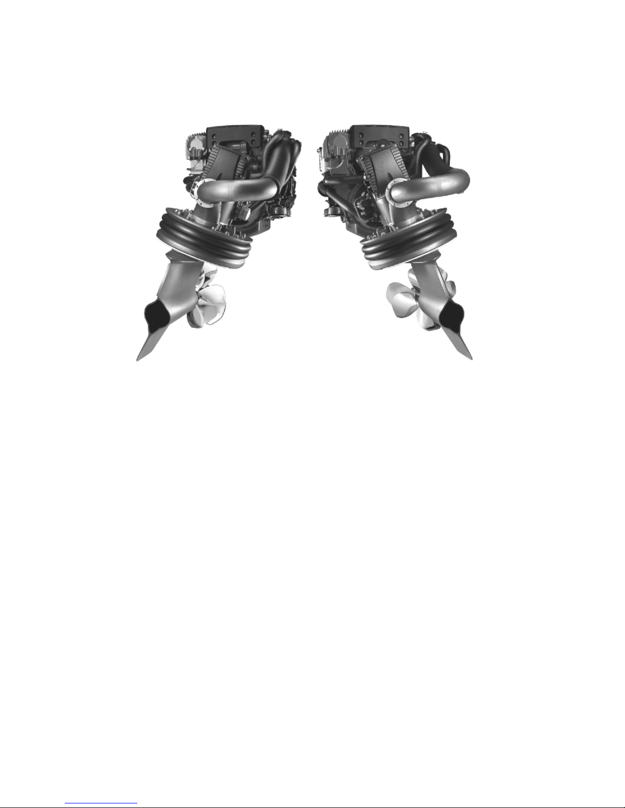
Presentation
Volvo Penta IPS - Inboard
Performance System
p0006599
Volvo Penta IPS overview
Volvo Penta IPS is setting a new standard:
- Much improved efficiency, higher top speed,
reduced fuel consumption/extended range and
great acceleration.
- Low-speed maneuvering is easier than ever
before, and high speed handling is a dream.
- Onboard comfort is greatly enhanced thanks to
much lower levels of sound and vibrations.
- Installation is greatly simplified.
- More space available for accommodation.
- Improved safety and quality.
- Ease of service and a complete system supported by one supplier.
- Improved overall environmental care.
Maneuvering and handling
The reasons for the amazing maneuverability are:
- The Volvo Penta IPS drive-units are steerable,
turning and pointing the entire thrust in the
desired direction. This results in much higher
efficiency and far greater response to driver
commands.
- Two counter-rotating propellers on each propulsion unit means that there are no lateral forces
to consider and that tracking is completely
straight.
- Electronic controls give a distinct and precise
feeling, and shifting is immediate. Thanks to the
progressive electronic steering, the wheel spins
easier at low speed, further reducing driver
effort.
All this is combined with the usual benefits of a traditional inboard such as a robust, high strength construction, excellent corrosion resistance and the
propellers under the hull.
10 7748921 04-2008

Comfort
Volvo Penta IPS new technology leads to major
improvements for all comfort enhancing factors.
- The propulsion forces and vibrations are absorbed by the combined rubber suspension and
sealing.
- A U-joint in the drive shaft makes it possible to
have the engine soft suspended, which efficiently reduces engine vibrations.
- The propellers are working in undisturbed water
with no cavitation, and have good clearance
from the hull.
- There is an increased number of propeller
blades to distribute the forces. This means that
the pulses created by the propellers have very
little effect on the hull.
- Exhaust fumes are truly minimized. First of all,
the new engine has very low exhaust emissions,
and secondly, the exhausts are emitted through
the propulsion unit into the prop wash and carried well behind the boat.
Environmental care
The Volvo Penta IPS has been developed as a complete system with excellent environmental performance as one of the main design targets. The very high
efficiency of the Volvo Penta IPS system gives greatly
reduced overall emissions.
Volvo Penta’s new D4/D6 in-line engines have been
developed from the latest design in modern diesel
technology. The engines have common rail fuel injection system, double overhead camshafts, 4 valves per
cylinder, turbocharger, compressor (Volvo Penta IPS
500), and aftercooler. The interaction of these, the
large swept volume, and the EVC system results in
exceptional diesel performance combined with low
emissions.
Installation
The Volvo Penta IPS system can be installed in various ways, either as a compact system or with an
extended jackshaft, giving opportunities for different
boat designs.
The system is always used in twin engine installation
configuration.
Safety and quality
Heavy duty material throughout means excellent corrosion resistance. Everything in contact with seawater
is either made from a specially formulated nickel-aluminum- bronze alloy or stainless steel. Propulsion
unit, bearings, couplings, etc. are all robustly dimensioned to cope with the unexpected and ensure a
really long and trouble-free service life.
EVC handles all communication and monitoring
including shift, throttle and steering. Several safety
functions in the system minimize the risk of damage
to engine or propulsion unit.
The Volvo Penta IPS system is designed with full
redundancy, i.e. even if you have a total breakdown
in one driveline, the remaining one will bring you home
safely.
Presentation
7748921 04-2008 11
Instruments and Controls
This chapter describes the instruments, panels and controls Volvo Penta sells for your engine.
If you would like to complement your instrumentation, or if your boat is equipped with instruments not described
here, we ask that you contact your Volvo Penta dealer.
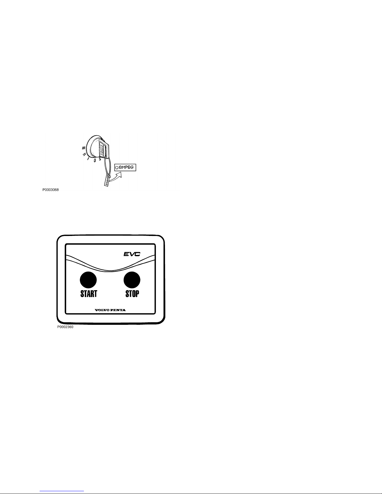
Ignition Lock
The start keys are supplied with a plate bearing the key
code to be used when ordering spare keys. Keep the
code beyond the reach of unauthorized people.
S = Stop position.
0 = The key can be inserted or removed.
I = Operating position. System voltage is connected.
II = Not used.
III = Start position. Start motor is engaged.
Read the starting instructions in chapter Starting page 31 to ensure you use the correct start
procedure.
Start/Stop Panel
The start/stop panel is used for starting and stopping
the engine.
To start the engine it is necessary for the start key at
the main station to be in the ”I” operating position. The
engine can only be stopped from an activated control
panel.
Read the starting instructions in chapter Start-
ing page 31 to ensure you use the correct start
procedure.
12 7748921 04-2008
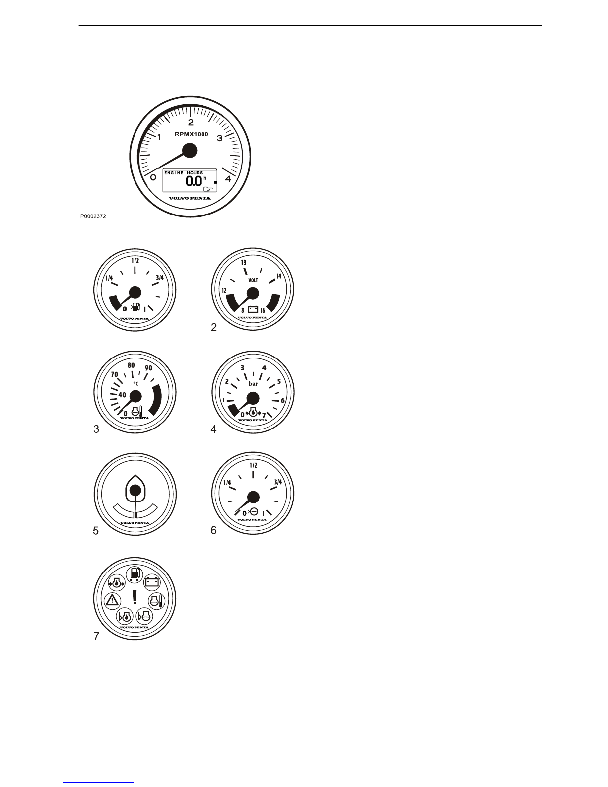
Gauges
Tachometer
The tachometer displays engine speed; multiply the
value shown on the dial by 1,000 to get the number of
engine revolutions per minute.
Boat and engine information is displayed in the tachometer window. Information displayed depends on
engine type, the number of sensors and which accessories are installed.
Optional instruments
These instruments are sold as engine options by Volvo
Penta.
1 Fuel level gauge
The fuel level gauge shows the quantity of remaining fuel.
2 Voltmeter, battery charging
The meter shows the alternator charge current.
During operations the charge voltage should be
around 14 V. When the engine is stopped and electrical power switched on the battery voltage should
be around 12 V.
If a 24 V system is installed, the charge voltage
should be around 28 V during operations.
3 Coolant temperature gauge
The instrument shows engine coolant temperature.
During operations coolant temperature should normally be between 75-90°C (167-194°F).
4 Oil pressure gauge
The oil pressure gauge displays engine oil pressure. During operations the oil pressure gauge
should normally show 4-5.5 bar. At idle, lower values are normal.
5 Rudder position indicator
The instrument shows rudder position.
6 Fresh water level sensor
Freshwater tank level gauge.
7 Alarm monitor
The alarm monitor gives a visual warning to call
attention to any alarms that occur.
1
P0005255
Instruments and Controls
7748921 04-2008 13
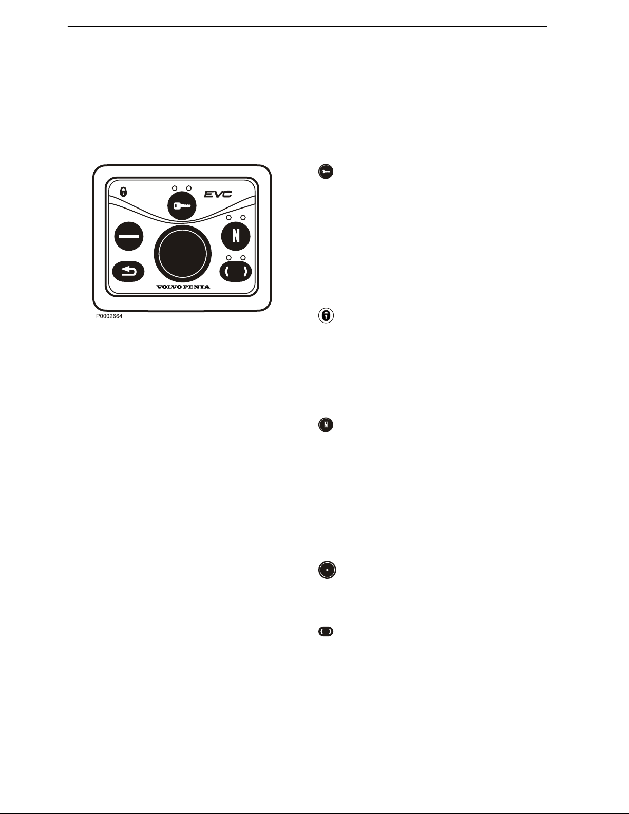
Control Panel
The control panel is used for station handling, disengaging the drive and to navigate the EVC system
menu.
Always push the buttons firmly and for at least one
second.
Activation button
The control panel and station are activated by pushing
the activation button once. Push twice to lock the station. On boats with only one station, this is always
active.
The lamp above the activation button shows the status
of the station.
Red lamp: Active station.
Lamp off: Station not activated.
Lamp flashing: A fault that limits the function of the
station has been detected.
Padlock
The padlock symbol lights when the station is locked
with the activation button or if change of stations is
under way, please refer to section Helm Sta-
tions page 36.
Lit: The station is locked and the boat can only be controlled from this station.
Flashing: Another station is locked.
Neutral button
The neutral button is used to disengage the drive enabling the engine rpm to increase without affecting the
drive, to warm up the engine. The lamp above the neutral button shows the status of the station.
Green lamp: Gear in neutral. The drive is in neutral
position and the engine runs at idle speed.
Lamp off: The drive is engaged for movement forward/
astern.
Flashing lamp: The drive is disengaged and the
engine speed can be adjusted.
Knob
Navigate the display menu by turning the knob.
Push the knob to confirm a selection or acknowledge
an alarm.
Tachometer Display Selection
Boats with one tachometer for port engine and one for
starboard can choose which engine menu to handle
from the station. The lamp above the button shows
which engine is chosen, green lamp for starboard
engine and red lamp for port engine.
Lamp off: Menu inactivated.
Lamp lit: Menu activated.
Instruments and Controls
14 7748921 04-2008
Multifunction Button
With the multifunction button the instruments and panels backlighting is adjusted.
Push the button for over a second to turn the backlighting on or off. The backlighting can be adjusted in
five stages by repeatedly pushing the multifunction
button quickly (less than 1 second).
If the button is pressed on an inactive station, operating
information is shown on the display(s) and the menu
structure is activated.
Back Button
Used to return a step up in the menu structure.
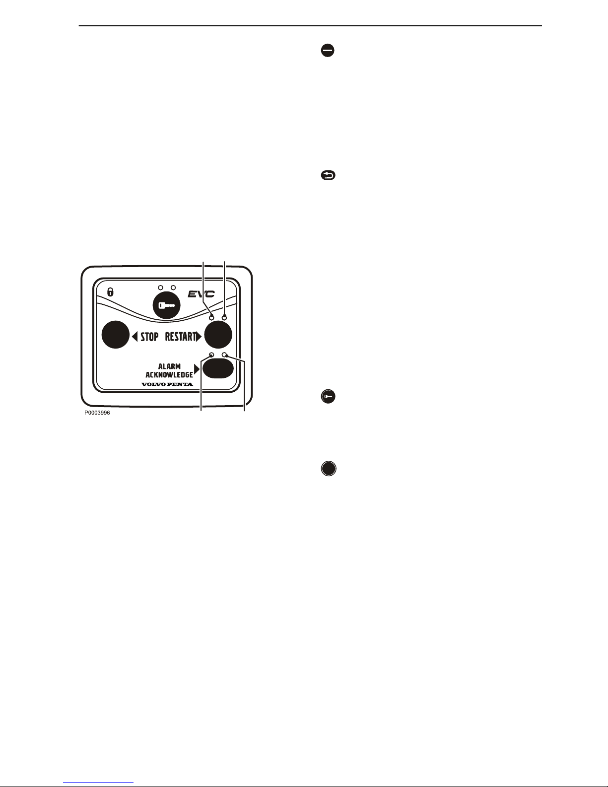
Docking Station Panel
The docking station panel allow stopping and restarting of the engines and handling of faults when operating the boat from a docking station.
The docking function (maneuvering with the joystick)
is enabled when the docking station is activated.
Please refer to the section Joystick page 23 for further information on docking.
Docking station can only be activated when the
engines are running.
Always push the buttons firmly and for at least one
second.
Activation button
Push this button on the docking station panel to activate and lock/unlock the docking station. Please refer
to section Instruments and Controls page 14 for further
information.
Stop and start buttons
Push these buttons to stop or restart the engines.
Both engines must be running when using the docking
function.
Lamp above the button: White
Lit: Port engine (1)/Starboard (2) engine are/is running.
Off: Port engine (1)/Starboard (2) engine are/is shut
off. Flashing and accompanied with a buzzer: The
engine(s) has stopped without a stop request. Silence
the buzzer with the Alarm acknowledge button and
restart the engine(s).
1
1
2
2
Instruments and Controls
7748921 04-2008 15
Alarm acknowledge button
Push this button to acknowledge an alarm of a fault. A
fault is always indicated with a flashing lamp above the
button and a more serious faults is also indicated with
a buzzer. When the fault is acknowledged the lamp will
light continuously and the buzzer will silence. The fault
pop-up must be read and acknowledged on a station
that is equipped with displays. Please refer to the
“Operation” chapter, section “Acknowleging alarms
and messages”.
Lamp above the button: Red
Flashing: Port (1)/Starboard (2) engine has a fault. Lit:
The fault is acknowledged.
Acknowledging faults on Docking Station
Since a docking station is not equipped with displays
and a control panel, an alarm of a fault is handled in a
different way.
On a docking station a fault is always indicated with a
flashing red lamp above the
Alarm acknowledge
button the docking station panel. The flashing lamp
indicates which engine (1/2/3) is faulty. A more serious
fault is also indicated with a buzzer.
1
Acknowledge the fault with the
Alarm acknowl-
edge button. The lamp above the button stops
flashing and lights continuosly. The buzzer is
silenced.
2 Activate a station that is equipped with displays in
order to read and acknowledge the fault pop-up.
3 Take the recommended actions. Please refer to
Fault Code Register page 45.
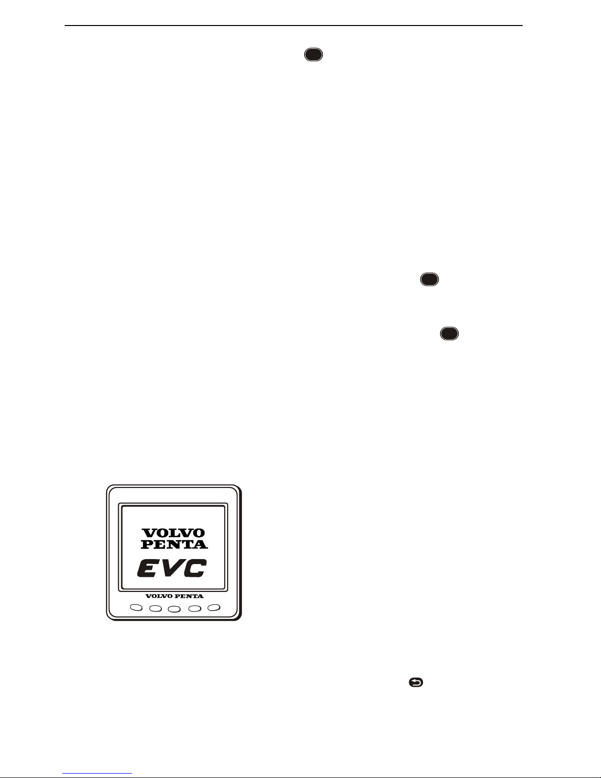
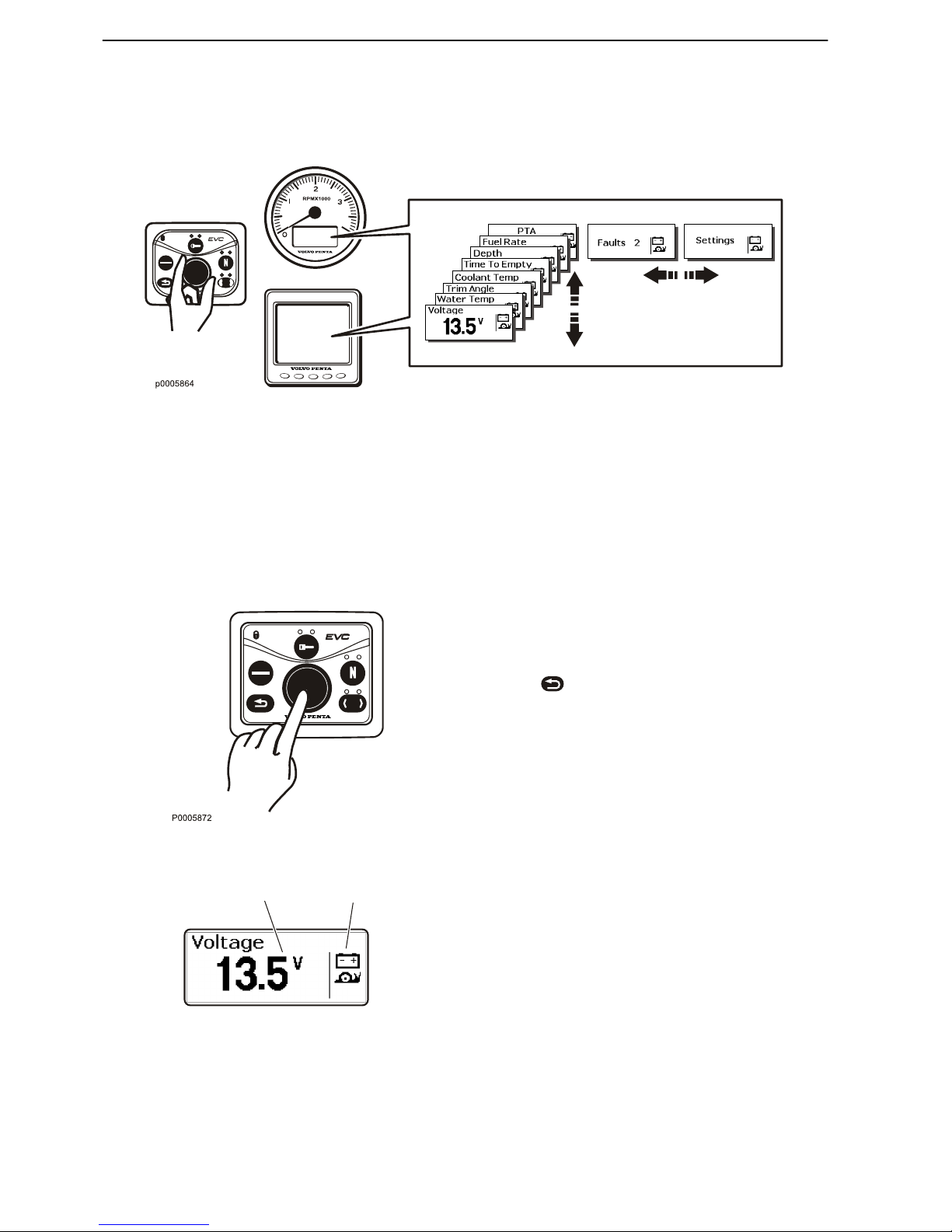
EVC System Display
In the EVC system display it is possible to show multiple windows with different information. There are four
display modes that can be chosen with the buttons on
the instrument.
Button 1–4 shows the different display modes. Button
5 i used to adjust the contrast and to access the configuration menu. Please refer to section Konfiguration-
smeny.
The EVC menu can be shown in the display by entering
Systeminformation (se section Multi, button 2) or the
Configuration menu. In this mode the display works the
same way as the display in the tachometer and is handled via the separate control panel, see chapter Instru-
ments and Controls page 20. If there is no tachometer installed the EVC meny can be reached by
pressing the knob on the control panel. To get back to
the display modes, press
.
At start up, the display performs a self-test. If an constant signal is heard, the system has discovered a
P0002383
Instruments and Controls
16 7748921 04-2008
malfunction. The display will work but may act in an
unexpected way.
NOTICE! Only installed functions will be shown in the
display.
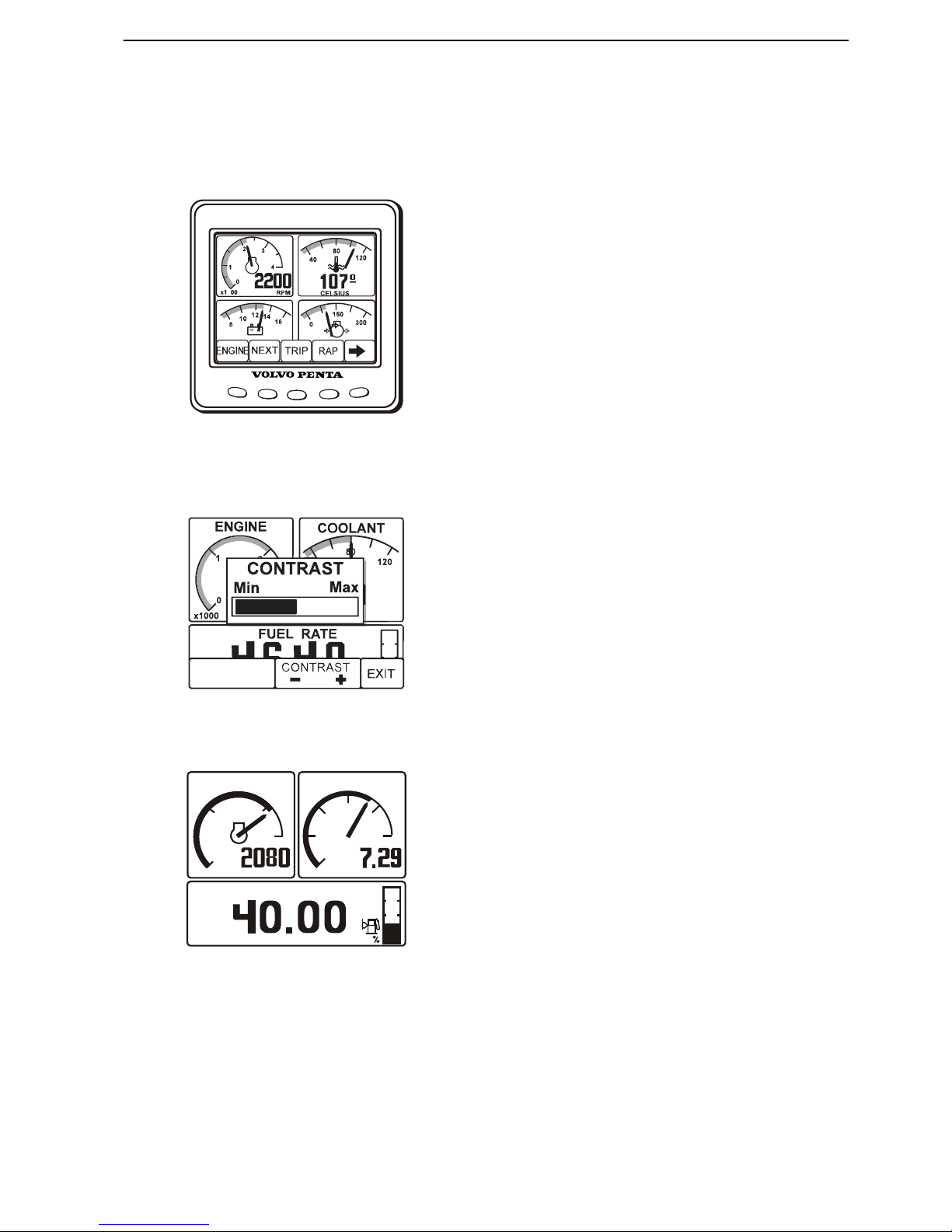
Display modes
Press button 1–4 to view the function menu for the
buttons, apperaring in the lower part of the display.
Press button 1–4 to choose the desired display mode.
1 Engine
2 Multi
3 Trip
4 Graph
To leave the menu, wait a few seconds or press button
5 (EXIT).
Contrast
In the display modes Engine, Trip and Graph, it is possible to adjust the contrast.
Press button 5 outside the menu and then + (button 4)
and – (button 3).
Engine, button 1
Rpm and speed is shown in the upper part of the display. In the lower part it will show trip computer and a
fuel level indicator, if these function are installed.
If speed information is missing, coolant temperature
will be shown instead.
Navigate in the trip computer by repeatedly press button 1.
•
Fuel Rate, fuel consumption per hours
•
Fuel Economy, fuel consumption per distance
•
Trip Fue, fuel used since last reset
•
Fuel Remaining, remaining fuel in tank
•
Dist. to Empty, remaining distance until tank
isempty, based on fuel consumption per distance
•
Trip Distance, trip distance since last reset
1 2
3
4 5
G H
P0002382
P0002403
ENGINE
FUEL RATE
SPEED
0
0
2
4
6
8
10
1
2
RPM KTS
L/H
29
x1000
P0002401
Instruments and Controls
7748921 04-2008 17
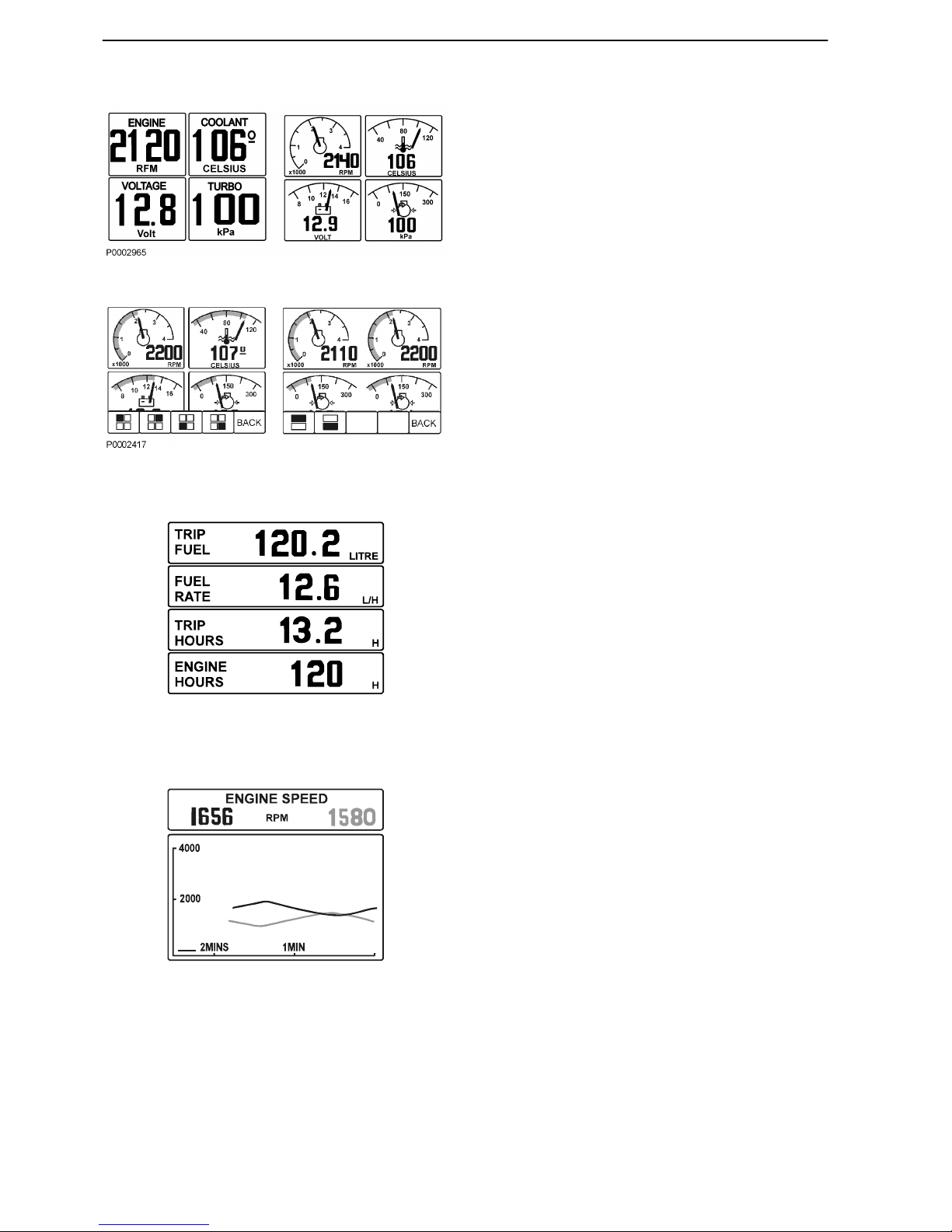
Multi, button 2
In the multi mode the information can be shown in several windows, analogue or digital. The display can
show windows with different information or be dividedto show windows and system information. To handle
the system information, see chapter Instruments and
Controls page 20. To go between the different display modes press button 2 repeatedly.
By pressing button 5, the right arrow, you choose what
information to be shown in the different windows. Press
repeatedly on the button that correspond to the window, until desired information is shown.
Trip, button 3
The display works as trip computer and shows:
Trip Fuel, since last reset
Fuel Rate, fuel consumption
Trip hours, since last reset
Engine hours, total amount of operating hours
Reset by pressing button 3 for three seconds until a
beep is heard.
The values from the engines are summarized, except
for engine hours that are shown for each engine.
Graph, button 4
The information is shown as graphs. Press button 4
repeatedly to choose what information will be shown.
The time interval is set in the Configuration menu.
If the connection is broken there will be a straight linein
the display.
The port engine is shown as a black line and the starboard engine as a grey line.
P0002418
P0002421
Instruments and Controls
18 7748921 04-2008
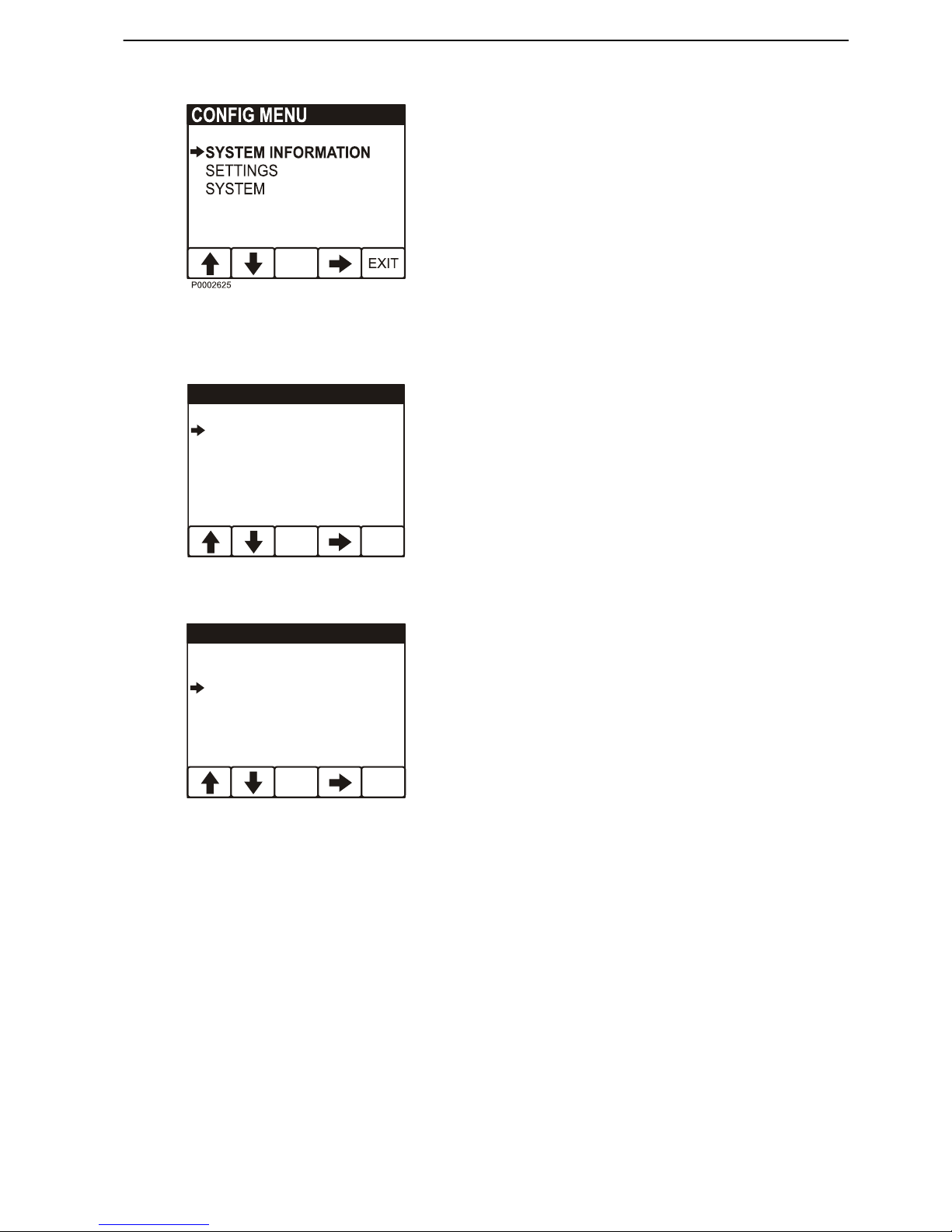
Configuration menu
Press button 5 for five seconds to enter the Configuration menu. Navigate with the up and down arrows,
select with the right arrow.
NOTICE! The port engine, or both engines must have
the ignition on when display settings are made.
System information
System information shows the EVC-menyn and is han-
dled by the knob on the control panel. For more information, see chapter Instruments and Con-
trols page 20.
Settings
- Language: Setting of what language the information is to be presented in are made in the EVCmenu, see Instruments and Controls page 20.
- Bleep: On/Off, setting if pressing the instrument
buttons will be followed by a beep or not.
- Engine: Setting of what kind of installation the display is a part of and which engine is to be shown
inthe display.
- Display: Setting of intervals (unit settings are made
in the EVC-menu, see Instruments and Con-
trols page 20):
Rpm interval, 2500–9000 rpm, in steps of 500 rpm
Speed, on/off
Speed interval, 10–100 knots, in steps of 10 knots
Graph interval, 2 min, 10 min, 30 min, 60 min, 2 h,4
h or 8 h
BACK
SETTINGS
LANGUAGE
BLEEP
ENGINE
DISPLAY
ENGLISH
OFF
PORT
P0002408
BACK
UNITS
SPEED
OIL PRESSURE
TURBO PRESSURE
FUEL RATE
DISTANCE
KM/H
KM
kPa
kPa
L/H
P0002409
Instruments and Controls
7748921 04-2008 19
EVC Menu
The EVC menu can be shown in both the EVC system
display and the tachometer display. The main menu
shows operating information, the settings menu and
the fault menu (only shown when a fault in the system
is detected).
Only installed functions are shown in the menu.
Turn the knob to navigate through the menus.
Press the knob to access sub menus and to confirm
selections in the settings menu.
It is always possible to return to the previous menu by
pressing
. Press repeatedly to return to the main
menu; alternatively, hold down the button for a couple
of seconds.
A This field displays engine operating data.
B This field displays warning symbols and active func-
tion symbols.
A
B
P0001006
Instruments and Controls
20 7748921 04-2008
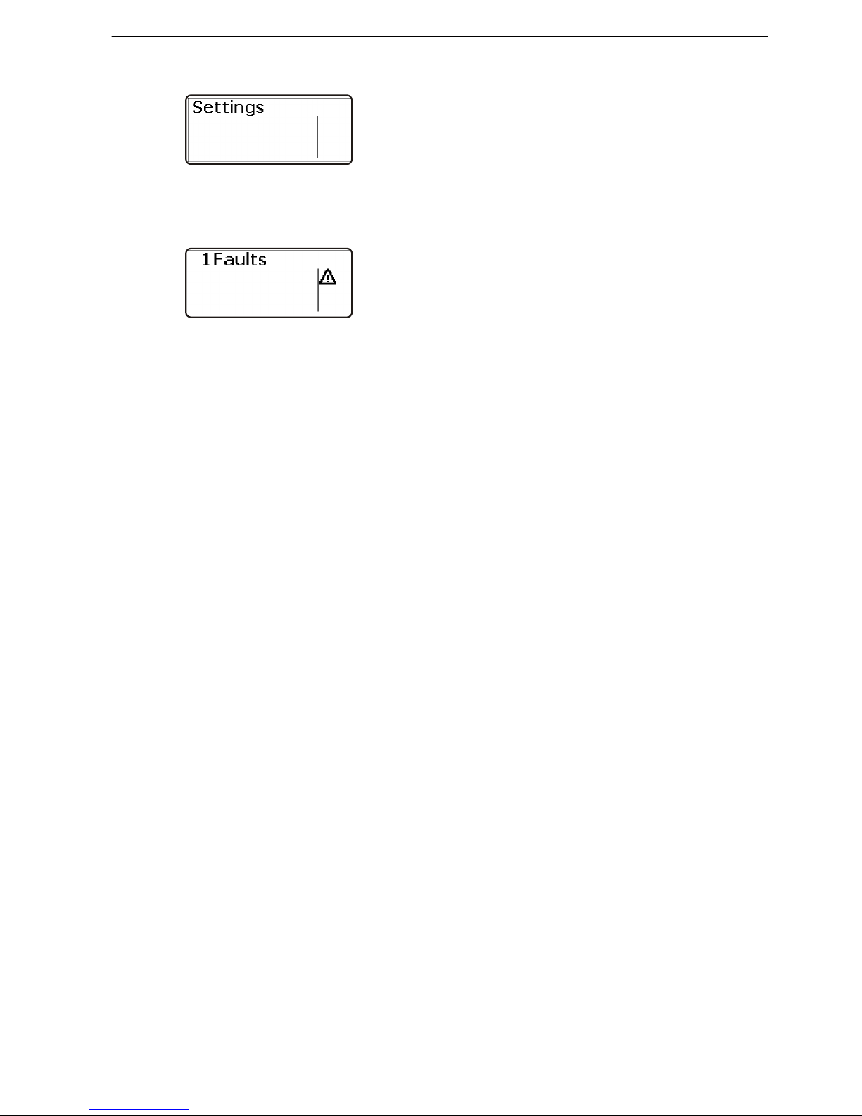
Settings
Turn the control panel wheel until the start screen for
the settings menu is displayed. Press the wheel to
reach the sub menus.
Turn to move between the available setting functions.
For further information, refer to section Settnings
menu page 102.
Fault
The fault window is only shown in the main menu if a
fault has been detected.
For further information, refer to section Fault Han-
dling page 41.
P0001015
P0001315
Instruments and Controls
7748921 04-2008 21

Controls
Single Lever Control
Maneuvering
A single-lever control operates both gearshift and
throttle functions with the same lever.
The engine can only be started with the control lever
in the neutral position.
N = Neutral position. Reverse gear/drive disengaged
and engine at idle.
F = Reverse gear/drive engaged for forward motion.
R = Reverse gear/drive engaged for rearward
motion.
T = Engine rpm control (throttle).
Disconnecting the gearshift function
The gearshift function can be disconnected so that the
control lever only operates the throttle.
1 Put the control lever in neutral (N).
2 Depress the neutral button (N) and keep it
depressed at the same time as the lever is moved
forwards to the gearshift position (F).
3 Release the neutral button. The green indicator will
flash as confirmation that the gearshift function is
disconnected and the that lever will only affect
engine revolutions.
The gear shift function is reconnected automatically
when the lever is returned to the neutral position. This
is confirmed by the green indicator shining continuously.
CAUTION!
Take care not to engage the gear by mistake.
P0006664
Instruments and Controls
22 7748921 04-2008
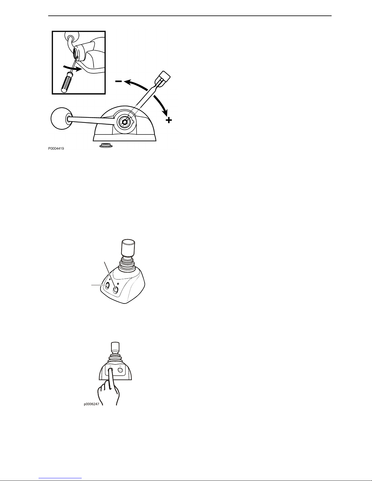
Adjusting the friction brake
The lever is fitted with a friction brake to allow adjustment for easier or stiffer movement as required. The
friction brake only affects movement of the throttle control lever.
1 Stop the engine.
2 Move the control lever forward so that the groove
in the lever hub is accessible.
3 Remove the plug with the aid of a screwdriver.
4 Adjust the friction brake (wrench, 8 mm) by turning
the bolt clockwise (+) for stiffer lever movement,
and counterclockwise (–) for easier movement.
5 Reinstall the plug.
Joystick
Volvo Penta IPS Joystick is a control used for docking
and maneuvering in low speed. The joystick makes it
possible to rotate the boat and maneuver the boat in
different directions – sideways, diagonally, forward
and backward.
Learn to handle the joystick in a safely and correct
manner before you start using the function in a marina.
When the docking function is active the engine speed
is reduced and the boat can only be maneuvered with
the joystick.
Activating the docking function
Before activating the docking function the following has
to be fulfilled:
•
the engines must to be running
•
the controls must to be in neutral
•
the helm station must be active
•
the joystick in its middle position
A
B
p0005186
A. Docking (ON/OFF)
B. Boost (ON/OFF)
Instruments and Controls
7748921 04-2008 23
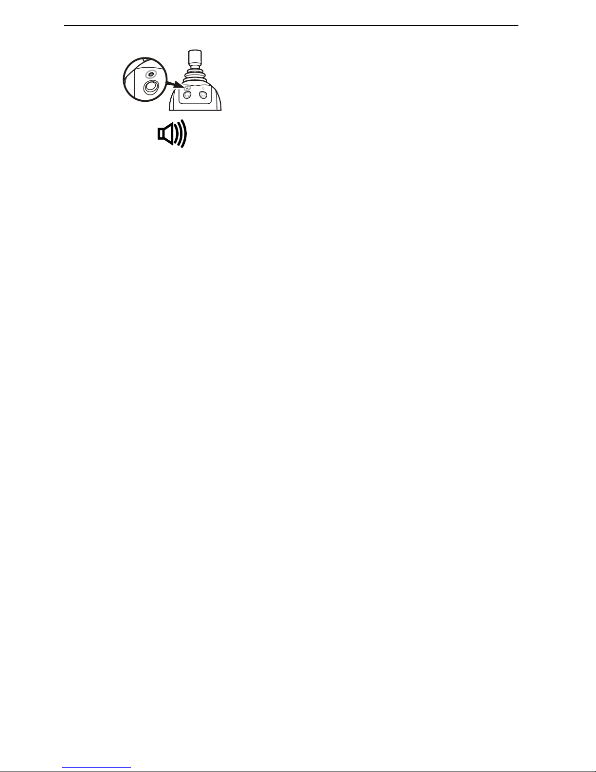
1 Activate the docking function by pressing the dock-
ing button (A) on the joystick.
2 A sound signal confirms that the docking function is
active and the lamp by the docking button is lit.
3 To inactivate the function press the docking button.
To confirm that the function is inactivated the signal
sounds twice and the lamp goes out.
4 The docking function is also deactivated if the con-
trols is moved out of neutral.
Activating the boost function
If the driver needs extra power, e.g. in windy weather
or if there is a strong currant, the boost function can be
activated.
1 Activate the boost function by pressing the boost
button (B) on the joystick.
2 A sound signal confirms that the function is active
and the lamp by the button is lit.
3 Inactivate the function press the boost button. To
confirm that the function is in active the signal
sounds twice and the lamp goes out.
4 The system is now back in docking mode.
P0006292
Instruments and Controls
24 7748921 04-2008
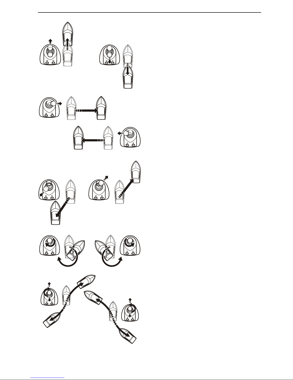
Maneuvering with joystick
To maneuver the boat move the joystick forwards, backwards, sideways or by turning the top of the joystick, see
figure.
IMPORTANT!
The boat keeps moving even after the joystick is
released, compensate this by moving the joystick in
opposite direction.
P0001191
Instruments and Controls
7748921 04-2008 25
Optional
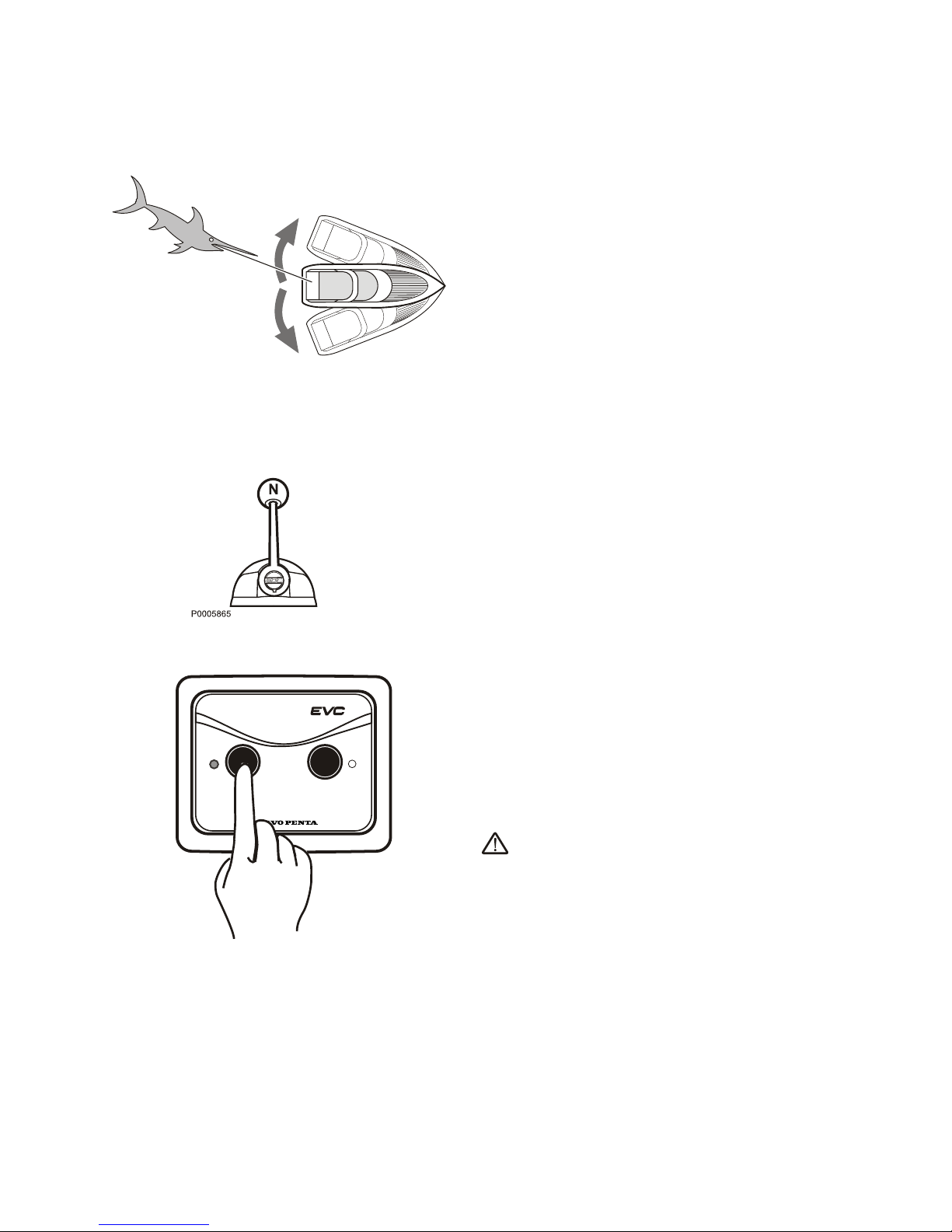
Sport Fishing Mode
Volvo Penta's sport fish function has been developed
by deep-sea fishermen. When the function is activated,
the IPS units are angled outwards and the helmsman
can quickly rotate and maneuver forward/backwards
to follow the movement of the fish. When activated, the
wheel is disconnected and the boat is maneuvered
solely via the control lever.
When the function is disengaged, both the IPS units
are set to straight forward.
The single-lever function used together with the sport
fish function makes it possible to control both engines
with just one of the control levers.
Activating the sport fish function
1 Move both control levers to neutral.
2 Press the sport fish button on the panel. The acti-
vation of the function is acknowledged by an acoustic signal and the lamp next to the button lighting.
An image stating that the sport fish function is active
is shown on the display for 5 seconds.
3 If the lamp flashes, all is not in order, e.g. the control
levers are not in neutral.
4 When the function is activated, the wheel is discon-
nected and the boat is steered with the control
lever.
5 Exit the function by pressing the sport fish button
on the panel. Inactivation of the function is acknowledged by an acoustic signal and the lamp next to
the button going out. An image stating that the function is inactive is shown on the display.
It is also possible to exit the function by turning the
wheel more than 30 degrees.
WARNING!
There is a risk that the boat may take in water if the
movements are too violent.
P0001219
SINGLE LEVER
SPORT FISH
P0001215
26 7748921 04-2008
Activating single-lever function
1 In order to activate the single-lever function, the
control levers must be roughly the same position,
max 10% difference.
2 Press the single lever button. The activation of the
function is acknowledged by an acoustic signal and
the lamp next to the button lighting. An image stating that the function is active is shown on the display
for 5 seconds.
3 When the function is activated, the control lever that
is moved first steers the boat and steers both
engines. The other control lever now has no function as long as the single lever function is activated.
4 To inactivate the function, the control levers must
again be in roughly the same position. Press the
single lever button; that the function is inactive is
confirmed by an acoustic signal and the lamp going
out. An image stating that the function is inactive is
shown on the display.
SINGLE LEVER
SPORT FISH
P0001214
Optional
7748921 04-2008 27
ACP
Volvo Penta ACP (Active Corrosion Protection) protects against galvanic corrosion by controlling an electric current that can be monitored by the engine
electrical system.
It is preferable to connect the boat to shore supply, if
such is available. If shore power is unavailable, ACP
utilizes the batteries, as it is connected to the boat's 12
V/24 V system. If the batteries begin to discharge, the
ACP switches from primary to secondary protection.
The IPS is then protected by the consumption of a
sacrificial zinc anode installed in the ACP unit on the
transom.
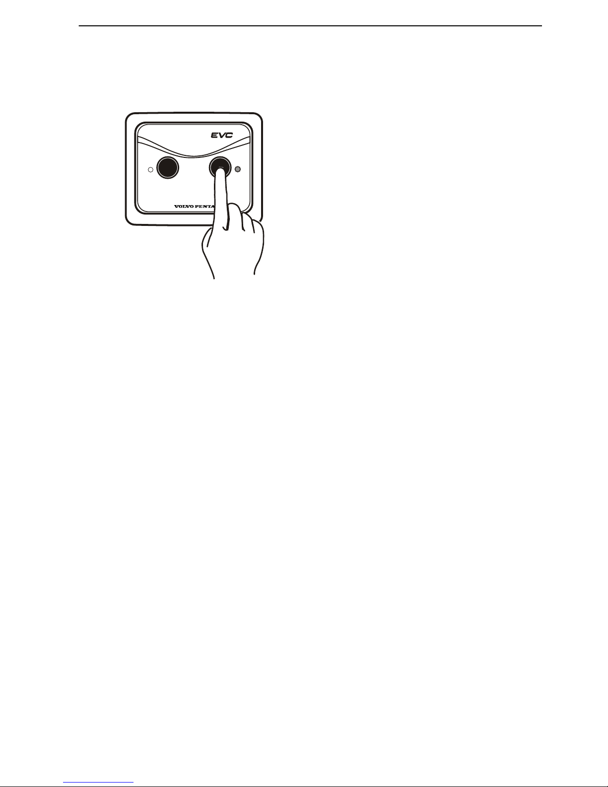
When the primary protection is in use, a small quantity
of chlorine gas is produced by the ACP; if desired it can
be switched off temporarily. The ACP then switches
over to secondary protection.
The ACP reverts automatically to normal mode after 4
hours; earlier reversion can be arranged in the settings
menu (see below) or when ignition is switched on.
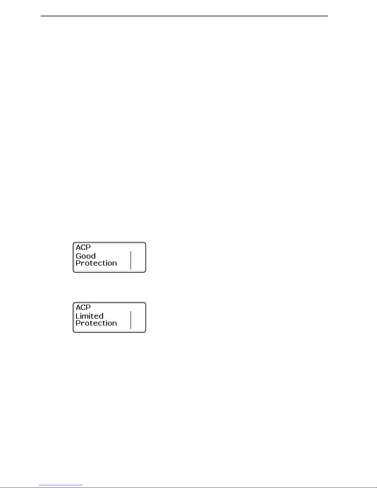
Protection levels
The ACP has three protection levels; the active level
is displayed in the EVC menu.
•
Good Protection; the IPS unit is optimally protected
by the ACP function.
•
Limited Protection; secondary protection - the IPS
has complete corrosion protection via the sacrificial
anode.
Check that the batteries are being charged by shore
power; alternatively, start the engine so that the
alternator charges the batteries.
There is no risk of corrosion as the sacrificial anode
protects the IPS. However, seek service for system
checks at the first suitable opportunity if the system
remains in the limited protection mode for more than
approx. 2 hours.
If the system remains in this mode for a longer break
in operations, more than 8 weeks, service should be
sought for system checks.
P0001217
P0003747
Optional
28 7748921 04-2008
 Loading...