

Volvo Penta D4, D6 Operator's Manual

OPERATOR’S MANUAL
D4, D6
CALIFORNIA
Proposition 65 Warning
Diesel engine exhaust and some of its constituents are known
to the State of California to cause cancer, birth defects, and
other reproductive harm.
This operator‘s manual is available in
English.
Compelte the form t the end of the operator‘s
manual to order a copy.
Diese Betriebsanleitung ist auch auf
Deutsch erhältlich.
Ein Bestellcoupon ist am Ende der Betriebsanleitung zu finden.
Ce manuel d’instructions peut être
commandé en français.
Vous trouverez un bon de commande à la fin
du manuel d’instructions.
Este libro de instrucciones puede solicitarse en español.
El cupón de pedido se encuentra al final del
libro.
Den här instruktionsboken kan beställas på svenska.
Beställningskupong finns i slutet av instruktionsboken.
Questo manuale d’istruzioni può essere ordinato in lingua italiana.
Il tagliando per l’ordinazione è riportato alla
fine del manuale.
Dit instructieboek kan worden besteld
in het Nederlands.
De bestelcoupon vindt u achter in het instructieboek.
Denne instruktionsbog kan bestilles
på dansk.
Bestillingskupon findes i slutningen af instruktionsbogen.
Tämän ohjekirjan voi tilata myös suomenkielisenä.
Tilauskuponki on ohjekirjan lopussa.
Este manual de instruções pode ser
encomendado em português.
O talão de requerimento encontra-se no fim
do manual.
Бхфь фп егчейсЯдйп чсЮузт
дйбфЯиефбй уфзн бгглйкЮ глюууб.
Гйб нб рбсбггеЯлефе Энб бнфЯфхрп,
ухмрлзсюуфе фз цьсмб рпх всЯукефбй уфп
фЭлпт бхфпэ фпх егчейсйдЯпх чсЮузт.
This operator’s manual is available in
Turkish/Russian.
Complete the form at the end of the operator’s
manual to order a copy.
Bu kullanýcý el kitabý Türkçe dillerinde mevcuttur.
Birnüshasýný sipariþ etmek için kullanýcý el
kitabýnýn sonundaki formu doldurun.
Welcome aboard
Volvo Penta marine engines are used all over the world. They are used in all possible operating
conditions for professional as well as leisure purposes. That’s not surprising.
After 100 years as an engine manufacturer the Volvo Penta name has become a symbol of reliability, technical innovation, top of the range performance and long service life. We also believe
that this is what you demand and expect of your Volvo Penta engine.
We would like you to read this operator’s manual thoroughly and consider the advice we give on
operation and maintenance before your maiden voyage so that you will be ensured of fulfilling
your expectations. Please pay attention to the safety instructions contained in the manual.
As owner of a Volvo Penta marine engine, we would also like to welcome you to a worldwide
network of dealers and service workshops to assist you with technical advice, service requirements and replacement parts. Please contact your nearest authorized Volvo Penta dealer for
assistance.
We also invite you to visit our home page on the Internet at www.volvopenta.com
With warm regards
AB VOLVO PENTA

Safety Information ............................................ 3–7
General ................................................................... 3
Boat travel...............................................................4
Maintenance and service ....................................... 6
Introduction ................................................... 8–12
Running-in ............................................................. 8
Fuel and oil types .................................................. 8
Certificated engines ............................................... 9
Warranty information ............................................. 9
Identification numbers ..........................................
12
Presentation ................................................... 13–20
Technical Description
............................................ 13
Engine monitoring and EVC ................................
14
Orientation ...........................................................
17
Instrumentation ..............................................21-44
Ignition lock ........................................................... 21
Start/stop panel ....................................................21
Instruments ........................................................... 22
Alarm display ........................................................ 23
EVC control panel................................................. 26
EVC system tachometer .......................................
27
EVC system display .............................................. 37
Controls .......................................................... 45-47
Starting the engine ........................................48-50
Before starting ......................................................
48
General about starting .......................................... 48
Starting method .................................................... 50
Operation .........................................................51-57
Reading instruments ...........................................
51
Acknowleging alarms and messages ................. 51
Cruising speed .....................................................
52
Synchronising engine speed .............................. 52
Changing helm station ........................................ 53
Operation ............................................................ 54
Power trim
........................................................... 54
Power trim Assistant ............................................ 58
Volvo Penta Lowspeed ....................................... 59
Running aground ..................................................
60
Stopping the engine ...................................... 61-62
Stopping ..............................................................
61
Laying up ............................................................. 61
Cold weather precautions .................................... 62
Maintenance schedule ................................... 63-65
Maintenance ................................................... 66–96
Engine, general ....................................................66
Lubrication system ............................................... 70
Freshwater system ............................................... 73
Seawater system .................................................. 76
Fuel system ......................................................... 80
Electrical system ..................................................
83
Reverse gear ........................................................
88
Drive ..................................................................... 90
Steering ................................................................ 93
Propellers .............................................................96
Laying up/Launching .....................................97-99
Inhibiting ............................................................... 97
Bringing out of winter storage ...............................
98
Painting the drive and underwater hull ................. 99
In case of emergency ..................................100-106
Starting using auxiliary batteries ........................ 100
Emergency shifting ............................................. 101
Emergency trimming .......................................... 102
Engine stop after crash-stop ............................... 102
Fault-tracing ........................................................ 103
Diagnostic function ............................................. 104
Malfunction message engine and EVC-system .. 105
Faults list ............................................................106
Erasing faults ..................................................... 106
Fault register ............................................... 107-113
Technical Data ............................................ 114-116
Engine ................................................................114
Fuel specification ............................................... 115
Drive .................................................................. 116
Reverse gear ...................................................... 116
Power Trim .......................................................... 116
Steering .............................................................. 116
© 2007 AB VOLVO PENTA
All rights to changes or modifications reserved.
Printed on environmentally friendly paper.
(Cover: Department of transport (shipping), license 9809095)
Contents
Safety Information
Read this chapter carefully. It concerns your safety. This section describes how safety information is presented in
the operator’s manual and on the engine. It also gives a general account of basic safety precautions to be taken
when operating the boat and maintaining the engine.
Check that you have the correct operator’s manual before you read on. If this is not the case please contact your Volvo Penta dealer.
If operations are performed incorrectly it could result in personal injury, or damage to property
or the engine. Read the operator’s manual carefully before operating or servicing the engine. If
anything is unclear please contact your Volvo Penta dealer for assistance.
This symbol is used in the book and on the engine to make you aware of safety information.
Always read these safety precautions very carefully.
In the operator’s manual warning texts have the following priority:
WARNING! If these instructions are not followed there is a danger of personal injury, exten-
sive damage to the product or serious mechanical malfunction.
IMPORTANT! Used to draw your attention to something that can cause damage, product
malfunction or damage to property.
NOTE! Used to draw your attention to important information that will facilitate work or opera-
tions.
This symbol is used in certain cases on our products and refers to important information in
the operator’s manual. Ensure that warning and information symbols on the engine and transmission are always visible and legible. Replace symbols that have been damaged or painted
over.
3
Safety precautions to be taken when operating the boat
Your new boat
Read operator’s manuals and other information
supplied with your new boat. Learn to operate the
engine, controls and other equipment safely and correctly.
If this is your first boat, or is a boat type with which
you are not familiar, we recommend that you practice controlling the boat in peace and quiet. Learn
how the boat behaves at different speeds, weather
conditions and loads before casting off for your “real”
maiden voyage.
Remember that the person driving a boat is legally
required to know and follow the current rules regarding traffic and safety at sea. Make sure you know the
rules that apply to you and the waters you are sailing
in by contacting the relevant authorities or organization.
A good piece of advice is to take a course in seamanship. We recommend that you contact your local
boating organization to find a suitable course.
Accidents
Statistics show that poor maintenance of boats and
engines and a lack of safety equipment are often the
cause of accidents at sea.
Ensure that your boat is maintained in accordance
with the relevant Instruction Manual and that the necessary safety equipment is on-board and is serviceable.
Daily checklist
Make a habit of checking the engine and engine
compartment visually before operating the boat (be-
fore the engine is started) and after operating the
boat (after the engine has been stopped). This will
help you to quickly detect fuel, coolant or oil leaks
and spot anything else unusual that has or is about to
happen.
Maneuvering
Avoid violent and unexpected changes in course and
gear engagement. This could cause someone on the
boat to lose their balance and fall over or overboard.
A rotating propeller can cause serious injury. Check
that nobody is in the water before engaging ahead or
astern. Never drive near bathers or in areas where
people could be in the water.
Avoid trimming an outboard drive too much, as steering will be severely reduced.
Refueling
When refueling there is always a danger of fire and
explosion. Smoking is forbidden and the engine must
be switched off.
Never overfill the tank. Close the fuel tank filler cap
properly.
Only use the fuel recommended in the operator’s
manual. The wrong grade of fuel can cause operating problems or cause the engine to stop. On a diesel
engine poor quality fuel can cause the control rod to
seize and the engine to overrev with a resultant risk
of damage to the engine and personal injury.
Do not start the engine
Do not start or run the engine with a suspected fuel
or LPG leak in the boat, nor when you are close to or
in a discharge of explosive media, etc. There is risk
for fire and/or explosion in explosive surroundings.
Safety breaker
We recommend that you install and use a safety
breaker (accessory), especially if you boat can travel
at high speeds. The safety breaker stops the engine if
the driver falls down and loses control over the boat.
Safety Information
4
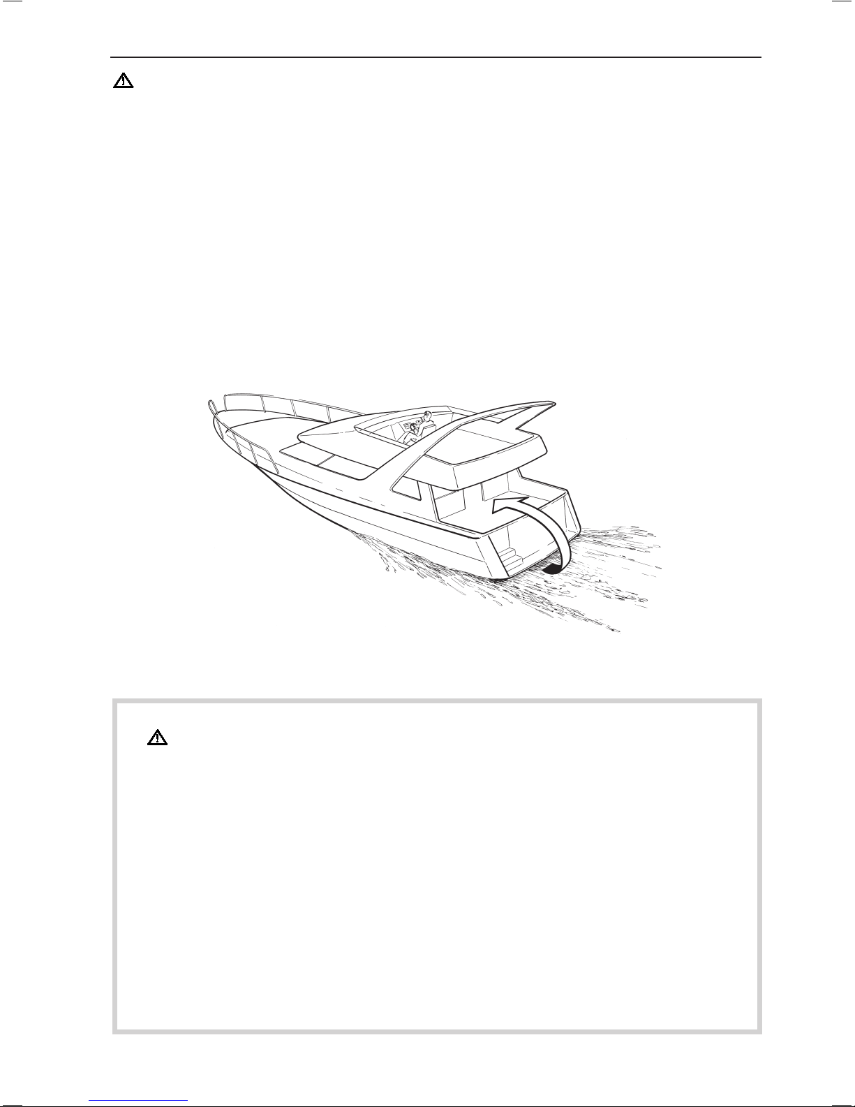
Carbon monoxide poisoning
When a boat is moving forward, it will cause a certain vacuum to form behind the boat. In unfortunate
circumstances, the suction from this vacuum can be
so great that the exhaust gases from the boat are
drawn into the cockpit or cabin and cause carbon monoxide poisoning.
This problem is most prevalent on high, wide boats
with abrupt stern. In certain conditions, however, this
suction can be a problem on other boats, e.g. when
running with the cover up. Other factors that can increase the effect of the suction are wind conditions,
load distribution, swells, trim, open hatches and portholes, etc.
Most modern boats, however, are designed in such
a way that this problem is very rare. If suction should
arise anyway, do not open hatches or portholes at
the fore of the boat. Surprisingly, this will otherwise
increase the suction. Try changing speed, trim or load
distribution instead. Try taking down/opening or in any
other way changing the setup of the cover as well.
Get in touch with your boat dealer for help in obtain
-
ing the best solution for your boat.
Checklist
● Safety equipment Life jackets for all passengers, communication equipment, emergency rockets,
approved fire extinguisher, first-aid equipment, life belt, anchor, paddle, torch etc.
● Replacement parts and tools: impeller, fuel filters, fuses, tape, hose clamps, engine oil, propeller
and tools for any repairs that might have to be carried out.
● Get out your charts and go over the planned route. Calculate distance and fuel consumption. Lis-
ten to the weather reports
● Make sure that relations or contact persons are informed when planning a longer voyage. Re-
member to inform them if your plans have changed or been delayed.
● Tell your passengers and crew where the safety equipment is stored and how to operate it. Make
sure you are not the only person on board who knows how to start the boat and operate it safely.
This list can be added to because safety equipment and other requirements vary depending on the
type of boat and how it is used. We recommend that you contact your local boating organization for
more detailed information on safety afloat.
Safety Information
5

Safety precautions for maintenance and service operations
Preparations
Knowledge
The operator’s manual contains instructions on how
to carry out general maintenance and service opera
tions safely and correctly. Read the instructions carefully before starting work.
Service literature covering more complicated operations is available from your Volvo Penta dealer.
Never carry out any work on the engine if you are
unsure of how it should be done, contact your Volvo
Penta dealer who will be glad to offer assistance.
Stop the engine
Stop the engine before opening or removing engine
hatches. Unless otherwise specified all maintenance
and service must be carried out with the engine
stopped.
To prevent accidental start of the boat engine remove
the ignition key, turn off the power supply to the engine at the main switches and lock them in the OFF
position before starting work. Put up a warning sign
in the control position that work on the engine is being carried out.
Approaching or working on an engine that is running is a safety risk. Loose clothing, hair, fingers or
a dropped tool can be caught in the rotating parts of
the engine and cause serious personal injury. Volvo
Penta recommend that all servicing with the engine
running be undertaken by an authorized Volvo Penta
workshop.
Lifting the engine
When lifting the engine use the lifting eyes installed
on the engine (reverse gear where installed). Always
check that lifting equipment is in good condition and
has sufficient load capacity to lift the engine (engine
weight including reverse gear and any extra equipment installed). For safety’s sake lift the engine using an adjustable lifting beam. All chains and cables
should run parallel to each other and as perpendicular as possible in relation to the top of the engine.
Bear in mind that extra equipment installed on the
engine may alter its center of gravity. Special lifting
equipment may then be required in order to maintain
the correct balance and make the engine safe to handle. Never carry out work on an engine suspended on
a hoist.
Before starting the engine
Reinstall all protective parts removed during service
operations before starting the engine. Check that no
tools or other items have been left on the engine.
Never start a turbocharged engine without installing
the air cleaner (ACL). The rotating compressor in the
Turbocharger unit can cause serious personal injury.
Foreign objects can also be sucked in and cause me
-
chanical damage to the unit.
Fire and explosion
Fuel and lubrication oil
All fuel, most lubricants and many chemicals are
inflammable. Read and follow the instructions on the
packaging.
When carrying out work on the fuel system make
sure the engine is cold. A fuel spill onto a hot surface
or electrical components can cause a fire.
Store fuel soaked rags and other flammable material
so that there is no danger of them catching fire. Fuelsoaked rags can self-ignite under certain conditions.
Do not smoke when filling fuel, oil or in proximity of a
filling station or in the engine room.
Non-original components
Components used in the fuel and ignition system
(gasoline engines) and electrical systems on Volvo
Penta products are designed and constructed to
minimize the risk of fire and explosion.
Using non-original Volvo Penta parts can result in fire
or explosion on board.
Batteries
The batteries contain and give off oxyhydrogen gas,
especially during charging. This gas is easily ignited
and highly volatile.
Do not under any circumstances smoke or use naked
flame or allow sparks in the vicinity of the batteries or
battery compartment.
Incorrectly connection a battery terminal cable or
jump-start cable can cause a spark which in its turn
can be sufficient to cause an explosion.
Start spray
Never use start spray or similar agents to start an engine equipped with air pre-heating (glow plugs/starter
element). This may cause an explosion in the inlet
manifold. Danger of personal injury.
Safety Information
6
Hot surfaces and fluids
There is always a risk of burns when working with
a hot engine. Beware of hot surfaces. For example:
the exhaust pipe, Turbo unit, oil pan, charge air pipe,
starter element, hot coolant and hot oil in oil lines and
hoses.
Carbon monoxide poisoning
Only start the engine in a well-ventilated area. If operating the engine in an enclosed space, ensure that
there is proper ventilation in order to remove exhaust
gases and crankcase ventilation emissions from the
working area.
Chemicals
Most chemicals such as anti-freeze, rustproofing
agent, inhibiting oil, degreasing agent etc. are hazardous to health. Read and follow the instructions on
the packaging.
Some chemicals such as inhibiting oil are inflammable and dangerous if breathed in as well. Ensure
good ventilation and use a protective mask when
spraying. Read and follow the instructions on the
packaging.
Store chemicals and other hazardous materials out
of the reach of children. To protect the environment
please dispose of used or leftover chemicals at a
properly designated disposal site for destruction.
Cooling system
There is a risk of flooding when working on the seawater system. Turn off the engine and close the sea
cock (where installed) before starting work on the
system.
Avoid opening the coolant filler cap when the engine
is hot. Steam or hot coolant can spray out and cause
burns.
If work must be carried out with the engine at operating temperature and the coolant filler cap or a cock
open or a coolant hose disconnected, open the coolant filler cap carefully and slowly to release pressure
before removing the cap completely. Note that the
coolant may still be hot and can cause burns.
Lubrication system
Hot oil can cause burns. Avoid skin contact with hot
oil. Ensure that the lubrication system is not under
pressure before commencing work on it. Never start
or operate the engine with the oil filler cap removed,
oil can spray out.
Fuel system
Always use protective gloves when tracing leaks.
Liquids ejected under pressure can penetrate body
tissue and cause serious injury. There is a danger of
blood poisoning.
Always cover the generator if it is located under the
fuel filter. The generator can be damaged by spilled
fuel.
Electrical system
Cutting off power
Always stop the engine and break the current using
the main switches before working on the electrical
system. Isolate shore current to the engine block
heater, battery charger, or accessories mounted on
the engine.
Batteries
The batteries contain an extremely corrosive electrolyte. Protect your skin and clothes when charging
or handling batteries. Always use protective goggles
and gloves.
If battery electrolyte comes into contact with unprotected skin wash off immediately using plenty of water and soap. If battery acid comes into contact with
the eyes, flush immediately with plenty of water and
obtain medical assistance without delay.
Safety Information
7

Introduction
This operator’s manual has been compiled to help you get the most from your Volvo Penta engine. It contains
all the information you need in order to operate and maintain your engine safely and correctly. Please read the
operator’s manual carefully and learn how to operate the engine, controls and other equipment safely.
Always have the operator’s manual available. Keep it in a safe place and do not forget to give it to the new owner
if you sell your boat.
Care of the environment
We would all like to live in a clean and healthy environment. Somewhere where we can breathe clean
air, see healthy trees, have clean water in our lakes
and oceans, and are able to enjoy the sunshine without being worried about our health. Unfortunately,
this cannot be taken for granted nowadays but is something we must work together to achieve.
As a manufacturer of marine engines, Volvo Penta has
a special responsibility, why care of the environment is
a core value in our product development. Today, Volvo
Penta has a broad range of engines where progress
has been made in reducing exhaust emissions, fuel
consumption, engine noise, etc.
We hope you will take care in preserving these qualities. Always follow any advice given in the instruction manual concerning fuel grades, operation and
maintenance and you will avoid causing unecessary
interference to the environment. Get in touch with your
Volvo Penta dealer if you notice any changes such as
increased fuel consumption exhaust smoke.
Adapt speed and distance to avoid wash and noise
disturbing or injuring animal life, moored boats, jetties,
etc. Leave islands and harbours in the same condition
as you want to find them. Remember to always leave
hazardous waste such as waste oil, coolant, paint and
wash residue, flat batteries, etc., for disposal at a destruction plant.
Our joint efforts will make a valuable contribution
to our environment.
Running-in
The engine must be run in for its first 10 operating
hours as follows: Operate the engine normally. Do not
operate it at full load except for short periods. Never
run the engine at a constant engine speed for long periods during the running-in period.
The engine can be expected to use more engine oil
during the running-in period than would otherwise be
normal. Check the oil level more often than is normally
recommended.
A First Service Inspection must be carried out after
20–50 running hours. For further information: See the
Warranty and Service Book.
Fuel and oils
Only use the fuel and oils recommended in the chapter Technical Data. Other grades of fuel and oil can
cause operating problems, increased fuel consumption and, in the long-term, a shorter engine service
life.
Always change oil, oil filters and fuel filters at the recommended intervals.
Service and replacement parts
Volvo Penta marine engines are designed for high
operational reliability and long service life. They are
constructed to withstand the marine environment
while also affecting it as little as possible. Through
regular service and the use of Volvo Penta original
spare parts, these qualities will be retained.
The Volvo Penta worldwide network of authorized
dealers are at your service. They are specialists in
Volvo Penta products and have accessories and
the original replacement parts, test equipment and
special tools necessary for high quality service and
repair work.
Always follow the maintenance intervals contained
in the operator’s manual. Remember to state the engine/transmission identification number when ordering service and replacement parts.
8
Warranty
Your new Volvo Penta marine engine is covered by a limited warranty according to the conditions and
instructions contained in the Warranty and Service book.
Note that AB Volvo Penta’s liability is limited to that contained in the Warranty and Service Book. Read
this book as soon as you take delivery of the engine. It contains important information about warranty
cards, service and maintenance which you, the owner, must be aware of, check and carry out. Liability
covered in the warranty may otherwise be refused by AB Volvo Penta.
Contact your Volvo Penta dealer if you have not received a Warranty and Service Book and a
customer copy of the warranty card.
Certified engines
It is important to be aware of the following information
if you own or run an engine that is exhaust emission
certified:
Certification means that an engine type is inspected
and approved by the authorities. The engine manufacturer guarantees that all engines manufactured of
that type correspond to the certified engine.
This places special requirements for maintenance
and service as follows:
● The maintenance and service intervals recom-
mended by Volvo Penta must be observed.
● Only genuine Volvo Penta replacement parts may
be used.
● The service of injection pumps and injectors or
pump settings must always be carried out by an
authorized Volvo Penta workshop.
● The engine must not be modified in any way
except with accessories and service kits approved
by Volvo Penta.
● No modifications to the exhaust pipes and air sup-
ply ducts for the engine may be undertaken.
● Seals may only be broken by authorized person-
nel.
Otherwise the general instructions contained in the
Operator's Manual concerning operation, service and
maintenance must be followed.
IMPORTANT! Late or inadequate maintenance/
service or the use of spare parts other than
Volvo Penta original spare parts will invalidate
AB Volvo Penta’s responsibility for the engine
specification being in accordance with the certificated variant.
Volvo Penta accepts no responsibility or liabil
ity for any damage or costs arising due to the
above.
Introduction
9
Declaration of Conformity for Recreational Craft Propulsion Engines with the
exhaust emission requirements of Directive 94/25/EC as amended by 2003/44/EC
Engine manufacturer:
AB Volvo Penta
Gropegårdsgatan
405 08 Göteborg
Sweden
This declaration of conformity is issued under the sole responsibility of the manufacturer. I declare on behalf of the engine manufacturer that the engine(s) mentioned above complie(s) with all applicable essential requirements in the way specified and is in conformity with the type for which above mentioned EC type examination certificate(s) has been issued.
Body for exhaust emission assessment
International Marine Certification Institute
Rue Abbé Cuypres 3
B-1040 Bruxells
Belgium
ID Number:0609
Module used for exhaust emission assessment .........B+C
Other Community Directives applied ...........................EMC 89/336/EEC
Description of engine(s) and essential requirements
Engine type .........................................................4 stroke diesel engine with stern drive with integral exhaust
Engine model(s) covered by this declaration EC Type certificate number
D4-180 ................................................................................EXVOLV001
D4-210 ................................................................................EXVOLV001
D4-225 ................................................................................EXVOLV001
D4-260 ................................................................................EXVOLV001
D4-300 ................................................................................EXVOLV001
D6-280 ................................................................................EXVOLV001
D6-310 ...............................................................................EXVOLV001
D6-330 ...............................................................................EXVOLV001
D6-350 ...............................................................................EXVOLV001
D6-370 ...............................................................................EXVOLV001
D6-435 ................................................................................EXVOLV001
D4, D6
Essential requirements
Annex I.B – Exhaust Emissions
Engine identification
Exhaust emission requirements
Durability
Operator’s manual
EMC Directive
Standards Used
Volvo Penta std
EN ISO 8178-1:1996
Volvo Penta std
ISO 10240:2004
EN 61000-3-2,
EN 61000-3-3,
CISPR 25
Other normative
document used
Annex 1.B.1
Annex 1.B.2
Annex 1.B.3
Annex 1.B.4
PL-99/07
Name and function: Sam Behrmann, Laws and Regulations
(identification of the person empowered to sign on behalf of the
engine manufacturer or his authorised representative)
Signature and title:
(or an equivalent marking)
Date and place of issue: (yr/month/day) 2007/04/26 Göteborg
10
Declaration of Conformity for Recreational Craft Propulsion Engines with the
sound emission requirements of Directive 94/25/EC as amended by 2003/44/EC
Engine manufacturer:
AB Volvo Penta
Gropegårdsgatan
405 08 Göteborg
Sweden
This declaration of conformity is issued under the sole responsibility of the manufacturer. I declare on behalf of the engine manufacturer that the engine(s) mentioned above complie(s) with all applicable essential requirements in the way specified and is in conformity with the type for which above mentioned EC type examination certificate(s) has been issued.
Module used for sound emission assessment ...... Aa
Internal production control
Test according to Annex VI
Other Community Directives applied ......................EMC 89/336/EEC
Description of engine(s) and essential requirements
Engine type .......................................................4 stroke diesel engine with stern drive with integral exhaust
Engine model(s) covered by this declaration EC Type certificate number
D4-210 drive DPH ........................................................ SDVOLV002
D4-225 drive DPH ........................................................
SDVOLV002
D4-260 drive DPH ........................................................ SDVOLV002
D4-300 drive DPH ........................................................ SDVOLV002
D6-280 drive DPH ........................................................ SDVOLV003
D6-310 drive DPR/DPH ................................................ SDVOLV003
D6-330 drive DPR/DPH ................................................ SDVOLV003
D6-350 drive DPR/DPH ................................................ SDVOLV003
D6-370 drive DPR/DPH ................................................ SDVOLV003
Body for sound emission assessment
International Marine Certification Institute
Rue Abbé Cuypres 3
B-1040 Bruxells
Belgium
ID Number:0609
D4, D6
Essential requirements
Annex I.C – Noise Emissions
Sound emission levels
Operator’s manual
EMC Directive
Standards Used
Other normative
document used
Annex 1.C.1
Annex 1.C.2
EN ISO 14509:2000/
prA1:2004
ISO 10240:2004
EN 61000-3-2,
EN 61000-3-3,
CISPR 25
PL-100/07
Name and function: Sam Behrmann, Laws and Regulations
(identification of the person empowered to sign on behalf of the
engine manufacturer or his authorised representative)
Signature and title:
(or an equivalent marking)
Date and place of issue: (yr/month/day) 2007/04/26 Göteborg
11

Identification numbers
Always provide the engine and transmission identification numbers when ordering service or replacement components.
The identification numbers are on an information decal located on the front edge of the engine. Note the information below. Make a copy of the page. Store the information so that it is available in event of the boat being
stolen.
Engine
Product designation (1*)
Serial number (2*)
Product number (3*)
Drive/Reverse gear
Product designation (4*)
Gear ratio (5*)
Serial number (6*)
Product number (7*)
Shield (Drive)
Product designation (8*)
Serial number (9*)
Product number (10*)
* The numbers refer to the position of the
identification numbers on the information decal
Introduction
Engine plate
Warranty decal, IMO decal and EPA decal
Drive plate
Reverse gear plate
Transom shield plate
Warranty decal
(Engine/Transom shield/Drive/Reverse gear )
Engine plate
Transom shield plate
Drive plate
Reverse gear plate
Location of information decal and identification plates:
12

Presentation
Volvo Penta’s D4 and D6 is developed from the latest design in modern diesel technology. The engine has common rail fuel injection system, double overhead camshafts, 4 valves per cylinder, turbocharger, compressor, and
aftercooler. The interaction of these, the large swept volume, and the EVC system results in exceptional diesel
performance combined with low emissions.
Technical description:
Engine block and head
— Cylinder block and cylinder head made of cast-
iron
— Combined ladder frame and balance shafts (D4)
— Ladder frame fitted to engine block (D6)
— Double overhead camshafts
— Oil-cooled pistons with two compression rings and
one oil scraper ring
— Integrated cylinder liners
— Replaceable valve seats
— Seven-bearing crankshaft
— Rear-end transmission
Engine mounting
— Flexible engine mounting
Lubrication system
— Easily replaceable separate full-flow and by-pass
oil filter
— Seawater-cooled tubular oil cooler
Fuel system
— Common rail fuel injection system
— Control unit for processing the injection
— Fine filter with water separator
— Emergency stop device
Air inlet and exhaust system
— Belt-driven compressor with silencer of absorption
type on both inlet and output port
— Air filter with replaceable insert
— Crankcase gases vented into the air inlet
— Exhaust elbow or exhaust riser
— Freshwater-cooled turbocharger
Cooling system
— Thermostatically regulated freshwater cooling
— Tubular heat exchanger with separate large vo-
lume expansion tank
— Coolant system prepared for hot water outlet
— Seawater strainer and easily accessible impeller
pump
Electrical system
— 12V/24V two-pole electrical system
— 115A/80A marine alternator with Zener-diodes to
protect the system from peak voltage, and integra-
ted charging regulator with battery sensor cable
for maximum use of alternator
— Fuses with automatic reset
Instruments/control
— Complete instrumentation including key switch
and interlocked alarm
— Digital Power trim instrument with analog or digital
reading
— EVC monitoring panels for single or twin installa-
tions
— Electronic remote control for throttle and shift
— Plug-in connections
Drive
— Complete with transom shield, and installation
components
— Max tilt angle 50° (adjustable)
— Protective zinc anodes to prevent corrosion
— Built-in kick-up function to reduce possible da-
mage, in the event the drive strikes an underwater
object
— Electrical shifting performed by electronic actuator
— Power trim with one-button operation in twin in-
stallation
— Fully integrated water inlet and exhaust system
— Fully hydraulic power-assisted steering system
— Isolated propellers to prevent corrosion
Reverse gear
— Reverse gear with matched drop center and 8°
down angel for compact installation and minimum
propeller shaft angel. V-drive available
— Bevel gears which resualts in smooth running at
all speeds
— Hydraulically operated clutch for smooth shifting
— Electrical shifting performed by elctromagnetic
valves.
— When under sail propeller shaft can rotate 24
hours without engine start.
— Seawater-cooled oilcooler
Accessories
— An extensive range of accessories are available.
For detailed information, please see Accessory
catalogs.
13
Engine Management System
The engines are equipped with common rail system
and electronically controlled injectors with an electronic control module.
The injectors contain an electro-magnetic valve which
sets the amount of fuel injected and the correct timing. The monitoring system measures the charge air
pressure and temperature, and calculates the available air mass. This determines the maximum amount
of fuel that can be injected (smoke limiter function).
The system also limits the maximum torque available
at the engine speed registered to protect the engine
from overload.
Engine Management and EVC system
To protect the engine at too high coolant or charge air
temperatures and boost pressure as well as oil pressure the monitoring system reduces the amount of
fuel (reduced engine output) until the current values
normalises.
The engine monitoring system also has a diagnostic
system, which helps users and service technicians to
determine the cause of malfunctions.
Users get information about faults by pop-ups that
are shown on the EVC system tachometer display.
Helm station Con-
trol Unit
(HCU)
Power train
Control Unit
(PCU)
Engine Management
System
(EMS)
Helm station Con
-
trol Unit
(HCU))
CAN bus
14
Presentation

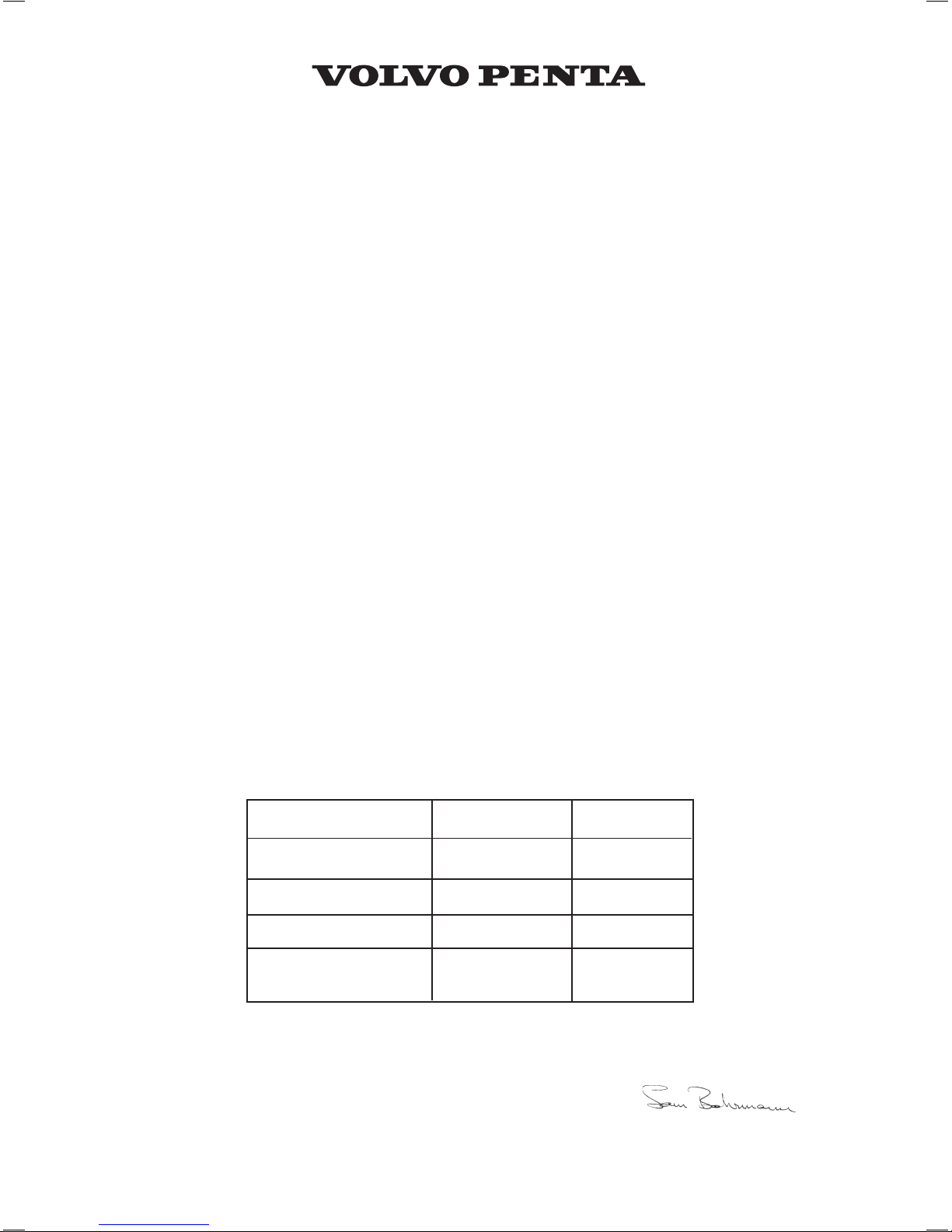
The EVC system
The Electronic Vessel Control (EVC) system is a so
called distributed system. The principle of a distributed system is to have many small electonic units,
called nodes, located on suitable places in the boat.
The EVC nodes are the Powertrain Control Unit
(PCU) and the Helm station Control Unit (HCU).
Nodes are located close to the components they
control. A helm node is located close to the helm. A
powertrain node is mounted in the engine room.
Each node controls a number of adjacent components, for example sensors, controls, instruments and
actuators.
Each PCU and HCU is programmed for a specific
engine individual. On the PCU and HCU there is a
sticker with chassis no. The chassis no. shall correspond to the sticker on the engine.
A data bus, a CAN bus, connects the nodes to each
other. Together they form a network and exchange
information and take advantage of each others’ services. The principle of forming a network of nodes to
which all components are connected reduces wiring
radically.
CAN stands for Controller Area Network, an industry
standard for communication between nodes in distributed systems.
A distributed system supports a growing multiplicity
of system configurations and optional features. New
nodes can be connnected to the network with minimal wiring redesign. New effective functionality can
be created by letting the nodes interact and combine
their capabilities, creating a more useful and safe
product.
Functionalities
Engine speed and gear shift
Speed and gear shift contol is handled electronically.
The reverse gear or stern drive has high speed shifting protection. Dual function electronic controls works
in the EVC system as well as mechanical controls
with control adapters.
Engine synchronization
Engine synchronization results in better comfort,
good fuel ecomomy and minimized wear due to less
vibration and reduced noise level. To enable synchronization the master (port) and slave (starboard)
systems must be able to communicate. Therefore a
synchronization cable has to be installed at the each
helm.
Instrumentation
The instruments use a serial communication bus. The
serial communication bus in combination with EVC
radically reduces wiring and simplifies installation.
Gauges are available with white or black dial face
and chromed or black bezel.
EVC system tachometer
The EVC system tachometer is mandatory for boats
with EVC, unless the optional EVC system display
is installed. The tachometer display shows operation
information, information massages and alarms. The
user selects what operation information to display
with the control panel.
NOTE! Only one operation in-
formation can be displayed at one and the same time.
The EVC system tachometer and control panel is
also used when calibrating EVC functions.
Power Trim
The function is considerably improved compared
to non EVC governed Power trim systems. EVC introduces a new trim panel with the same design as
other EVC control panels. If you have a twin engine
installation the stern drives can be both individually
and simultaneously controlled.
Trimming in and out can be calibrated to suit the specific installation. To protect the drive it cannot be tilted
when engine is running above a certain rpm.
The Power trim control panel shall be connected to
the multilink bus and the gauge to the instrument
cable harness from the HCU. The cable harness for
stern drives has connectors for the power trim angle
sensor and the power trim pump.
Extra optional equipment
EVC system display
The EVC system display is a complement or replacement for EVC system tachometer and optional instruments. The display shows operation information,
information massages and alarms. The user selects
what operation information to display with the buttons
on the display. The EVC system display can display
more than one operation information at one and the
same time. The display also has access to the same
display mode and calibration functions as for the EVC
system tachometer display.
Trim indicator
A trim indicator sender is included in all aquamatic
drives. The trim angle can be displayed on the EVC
system tachometer. It is also advised to install a trim
instrument. The instrument shows trim angle and trim
range. If a trim instrument is used it must be connected to the instrument serial communication bus.
Fuel level
Fuel level can be displayed on the EVC system tachometer if a (3-180 ohm or 240-30 ohm) fuel level
sender is installed in the fuel tank. The sender is
connected to the PCU–engine cable harness. If a
fuel level gauge is used it must be connected to the
instrument serial communication bus.
15
Presentation

Fresh water level
Fresh water level can be displayed on the EVC system tachometer if a (3-180 ohm) fuel level sender is
installed in the water tank. The sender is connected to
the PCU–engine cable harness. If a fresh water level
gauge is used it must be connected to the instrument
serial communication bus.
Rudder indicator
Rudder angle can be displayed on the EVC system
tachometer if a (3-180 ohm) rudder indicator is installed to the drive/rudder. The sender is connected to
the PCU–engine cable harness. If a rudder instrument
is used it must be connected to the instrument serial
communication bus.
Multisensor (Boat speed, depth and water temp)
Boart speed, depth and water temperature canbe displayed on the EVC system tachometer if a multi sensor is installed on the boat. The sensor is connected
to the multilink cable. If instruments (speed, depth,
water temp.) are used they must be connected to the
instrument serial communication bus.
Power Trim Assistant
The function power trim assistant adjust trim angle
automatically according to engine speed (rpm). EVC
supports power trim assistant if software for powertrim assistance is installed (order and download from
VODIA website).
Boat speed
Boat speed can be shown on the EVC system tachometer, if a multisensor or NMEA 0183/NMEA 2000
compatible component (plotter, GPS, paddle wheel
etc) is installed. If a speedometer is used it must be
connected to the instrument serial communication
bus. .
Trip computer
EVC supports trip computer functions if following are
installed.
- Multisensor or NMEA 0183/NMEA 2000 compatible component (plotter, GPS, paddle wheel etc)
- Fuel level sender
- Software for trip computer (order and download
from VODIA website).
Trip computer information can be displayed on the
EVC system tachometer or/and on the optional EVC
system display.
16
Presentation
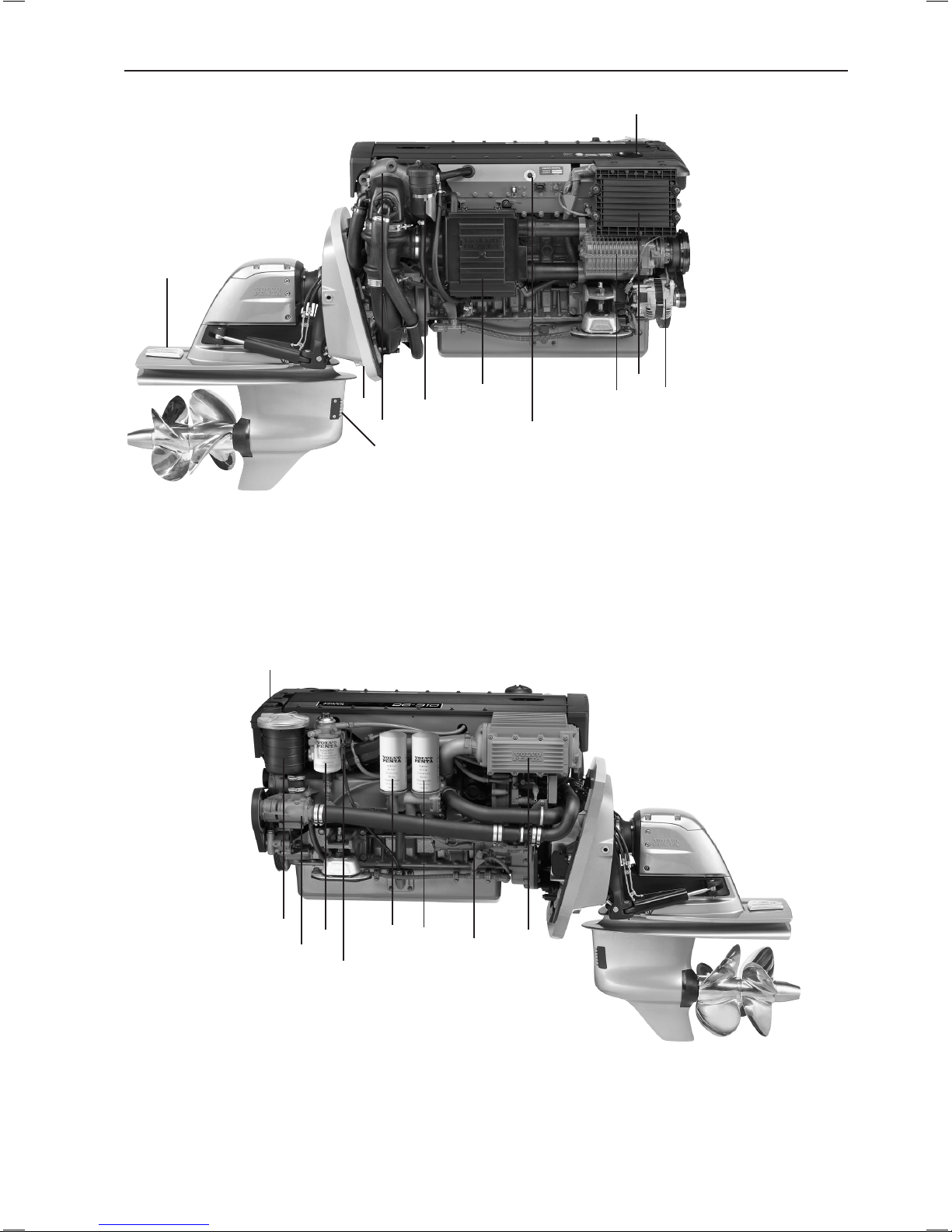
Orientation
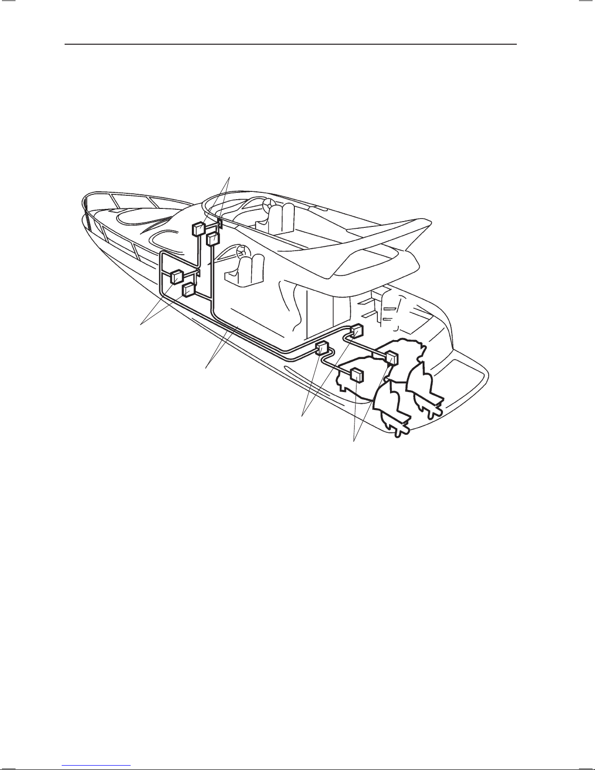
D4 with drive, port
11. Sea water filter
12. Sea water pump
13. Fuel filter
14. Oil dipstick
15. Oil bypass filter
16. Oil filter
17. Starter
18. Charge air cooler
19. Expansion tank
D4 with drive, starboard
1. Zinc anode
2. Cooling water intake
3. Zinc anode
4. Turbocharger
5. Crankcase ventilation filter
6. Aux Stop
7. Air filter
8. Compressor
9. EDC control module
10. Generator
11. Oil filler cap
1
2
3
4
5
6
7
8
9
11
10
11
12
13
14
15
16
17
18
19
17
Presentation
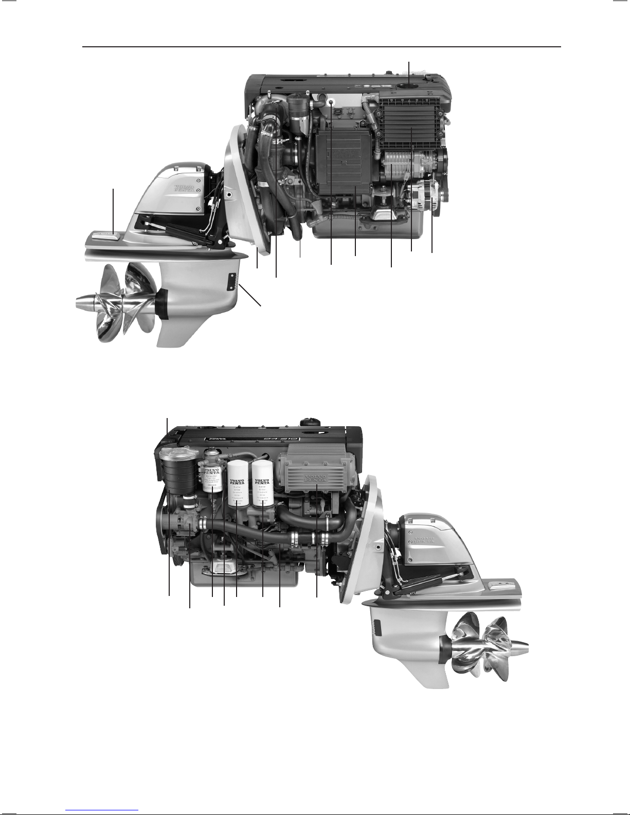
D4 with reverse gear, port
8. Sea water pump
9. Fuel filter
10. Oil dipstick (engine)
11. Oil bypass filter
12. Oil filter
13. Starter
14. Charge air cooler
15. Oil dipstick (reverse gear)
16. Expansion tank
D4 with reverse gear, starboard
1. Turbocharger
2. Crankcase ventilation filter
3. Aux Stop
4. Air filter
5. EDC control module
6. Generator
7. Oil filler cap
8
9
10
11
12
13
14
15
16
1
2
3
4
5
6
7
18
Presentation
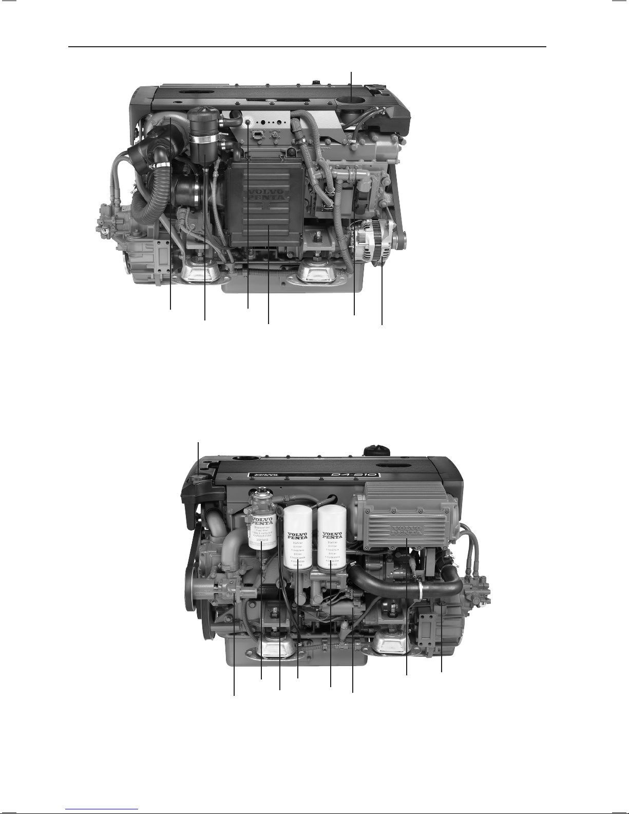
D6 with drive, starboard
1. Zinc anode
2. Cooling water intake
3. Zinc anode
4. Turbocharger
5. Crankcase ventilation filter
6. Aux Stop
7. Air filter
8. Compressor
9. EDC control module
10. Generator
11. Oil filler cap
D6 with drive, port
11. Sea water filter
12. Sea water pump
13. Fuel filter
14. Oil dipstick
15. Oil bypass filter
16. Oil filter
17. Starter
18. Charge air cooler
1
2
3
4
5
7
6
8
9
11
11
12
13
14
15
16
17
18
19
10
19
Presentation
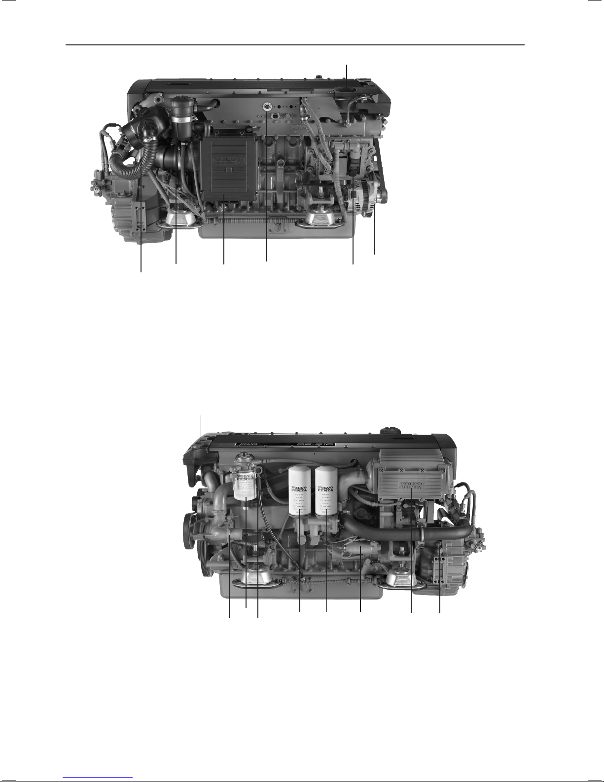
D6 with reverse gear, starboard
1. Turbocharger
2. Crankcase ventilation filter
3. Air filter
4. Aux Stop
5. EDC control module
6. Generator
7. Oil filler cap
D6 with reverse gear, port
8. Sea water pump
9. Fuel filter
10. Oil dipstick (engine)
11. Oil bypass filter
12. Oil filter
13. Starter
14. Charge air cooler
15. Oil dipstick (reverse gear)
16. Expansion tank
8
9
10
11
12
13 14 15
16
1
2
3
4
5
6
7
20
Presentation
Instruments
This chapter describes the instrument and control panels sold by Volvo Penta for your engine.
If you want to supplement the instrumentation, or if your boat is equipped with instruments not described here,
or you are not sure about their function, please contact your Volvo Penta dealer.
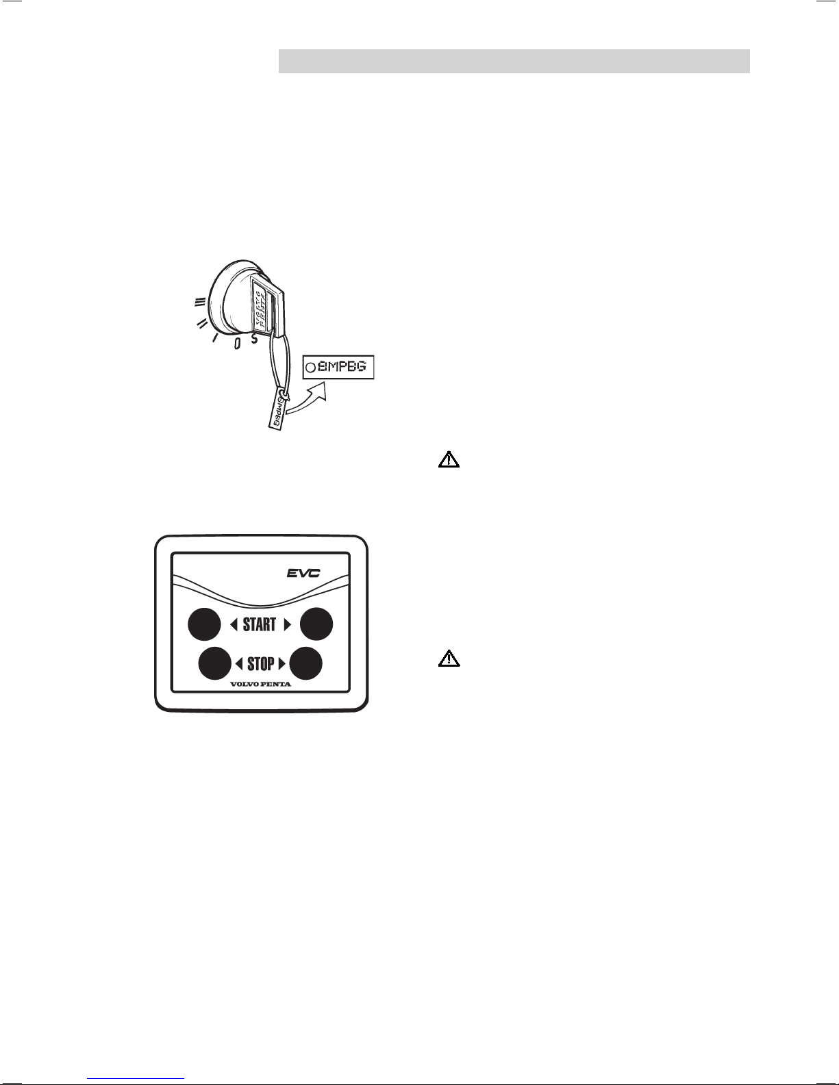
Ignition lock
A tab with the key code accompanies the ignition
keys, and is used to order extra ignition keys. Do not
store the code where it is accessible to unauthorized
persons.
S = Stop position.
0 = Key can be inserted and removed.
I = System voltage on (drive position).
II = Not used.
III = Start position.
IMPORTANT! Read the starting instructions in
the “Engine starting” chapter.
Start/stop panel
The start/stop panel is used to start or stop the engine. The starter key on the main helm station must be
in position “I” (driving position) for the engine to start.
The engine can only be stopped if the control panel is
activated.
IMPORTANT! Read the starting instructions in
the “Engine starting” chapter.
21
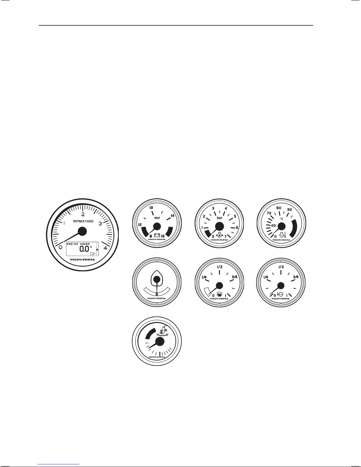
Instruments
1. EVC system tachometer (with display)
Extra optional instruments
2. Voltmeter
3. Oil pressure gauge
4. Temperature gauge
5. Rudder indicator
6. Fuel level gauge
7. Water level gauge
8. Trim instrument
2.
3.
4.
1.
6.
7.
5.
8.
22
Instruments
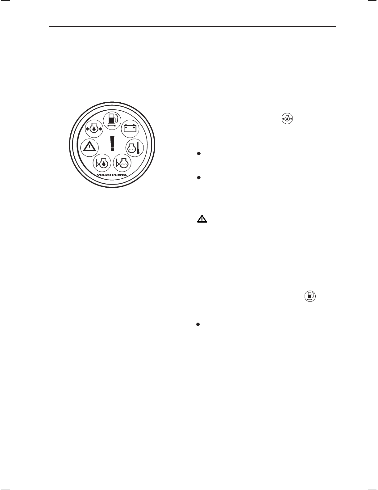
Alarm display (extra optional)
The following warning lamps should never light up during operation. On the other hand, the warning lamps light
up when the starter key is first turned to the drive position. Check that all lamps function. When the engine has
started, all lamps should have gone out. The lamps flash if the diagnostic function has registered malfunction.
When the fault has been acknowledged, the lamp gives continuous light.
Warning lamps (should never light up
during operation).
Oil pressure (red indication)
If the oil pressure lamp lights up during operation, the
oil pressure in the engine is too low. Stop the engine at
once.
Check the oil level in the engine. Please refer to
“Maintenance: Lubrication” to check and top the oil
up.
Also check that the oil filters are not blocked.
Please refer to “Maintenance: Lubrication system”
Please refer to the “In case of emergency” chapter,
and you will find detailed information about recommended action in the “Diagnostic function” section.
WARNING! Continued operation when the oil
pressure is too low can cause serious engine damage.
Water in fuel filter (orange indication)
If the lamp lights up, there is too much water in the water trap in the fuel filters.
Empty the water trap underneath the fuel filter on
the engine and pre filters. Please refer to “Maintenance: Fuel system”.
23
Instruments
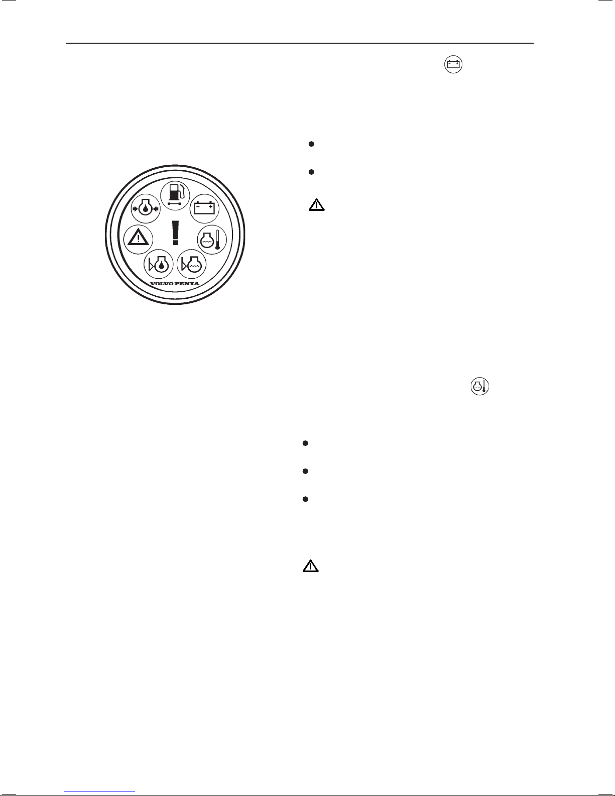
Battery (orange indication)
The battery lamp lights up if the alternator is not
charging. Stop the engine if this lamp lights up during
operation. If the lamp lights up, this can be due to a
fault in the electrical system or because the alternator
drive belt is slack.
Check the alternator drive belts. Please refer to
“Maintenance: Engine, general”.
Also check that there is no poor contact/broken wires.
WARNING! Do not continue operation if there is
any problem with the alternator drive belts. This
could cause serious engine damage.
Coolant temperature (red indication)
The coolant temperature lamp lights up when the
coolant temperature is too high. Stop the engine if this
lamp lights up during operation.
Check the coolant level. Please refer to “Maintenan-
ce: Fresh water system”.
Check that the sea water filter is not blocked. Please
refer to “Maintenance: Sea water system”
Also check the impeller in the sea water pump.
Please refer to “Maintenance: Sea water system”.
Please refer to the “In case of emergency” chapter, and
you will find detailed information about recommended
action in the “Diagnostic function” section.
WARNING! Do not open the coolant filler cap
when the engine is warm, except in emergencies.
Steam or hot fluid could spray out.
24
Instruments
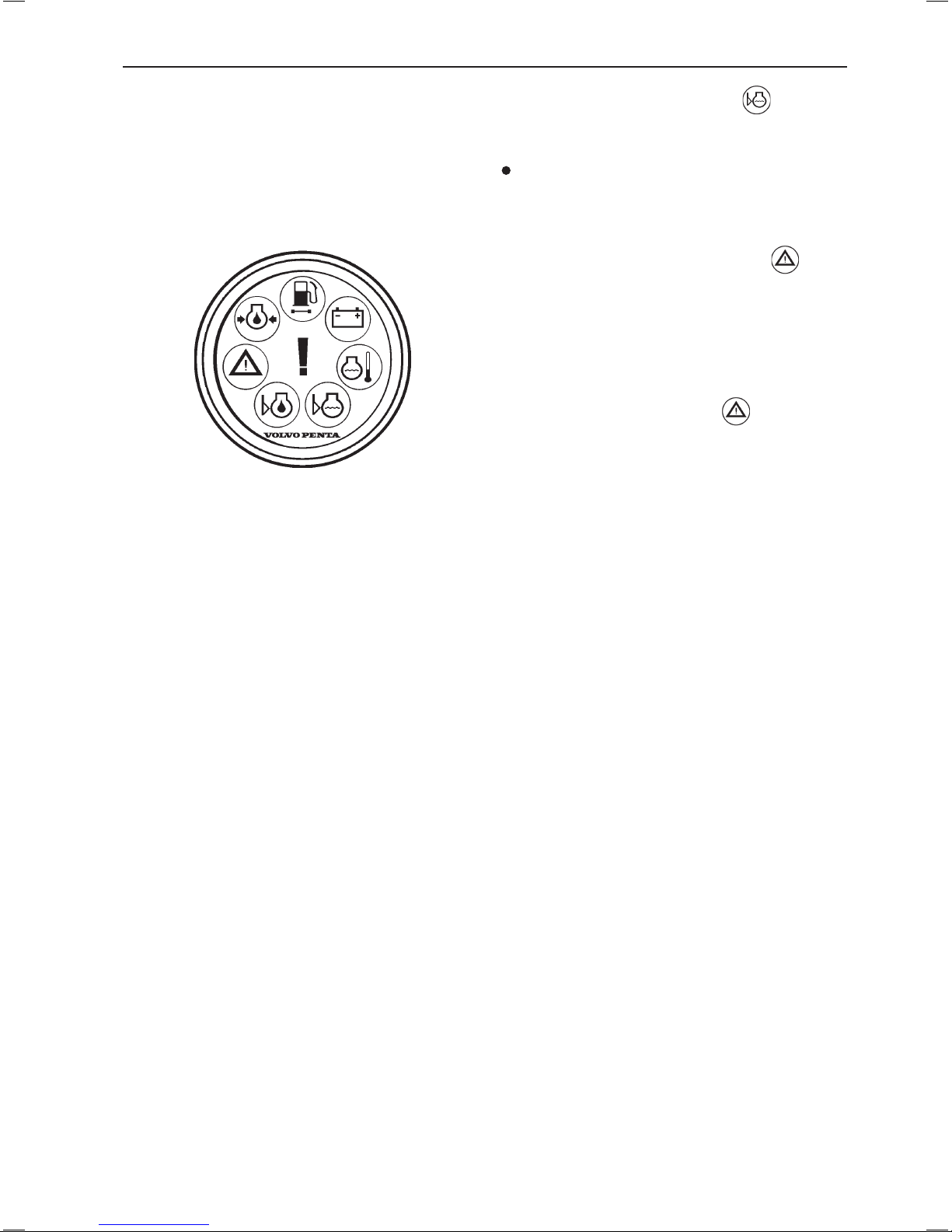
Coolant level (orange indication)
The coolant lamp lights up when the coolant level is
too low.
Check coolant level. Please refer to “Maintenan-
ce: Fresh water system”.
Red warning indication, serious fault
If the red warning indication is shown during operation, a serious fault has occured.
Please refer to the “In case of emergency” chapter,
and you will find detailed information about recommended action in the “Diagnostic function” section.
Orange alarm indication, fault
If the orange alarm indication is shown during opera
-
tion, a fault has occured.
Please refer to the “In case of emergency” chapter,
and you will find detailed information about recommended action in the “Diagnostic function” section.
25
Instruments
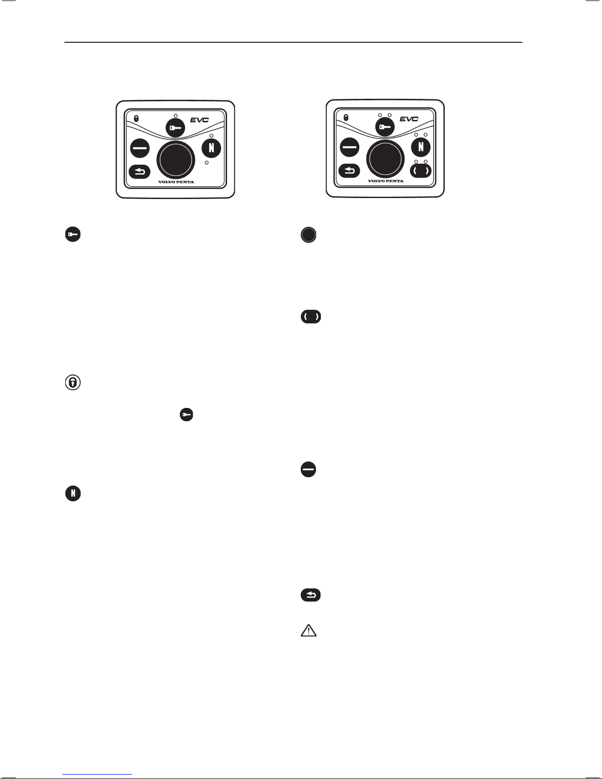
Navigation wheel
Used to navigate through the menus shown on the
tachometer EVC system display. Navigate through
the menus by turning the wheel. Depress the wheel to
confirm a selection.
Tachometer display selection (twin installa-
tion, port or starboard tachometer)
Is used to select which of the engines menu systems
should be navigable from the control panel. The menu
is shown on the display of the corresponding engines
tachometer. Select port or starboard.
Indication (red/green):
Off: Not possible to navigate in menu.
Lit: Possible to navigate in menu for selected engine,
port (red), starboard (green).
Multifunction button
Used to increase or decrease the instrument’s and
panel’s backlighting.
Depress the button for at least 1 second to turn the
backlighting on or off. The backlighting can be adjust
-
ed in five stages by pressing the multifunction button.
If the button is pressed on a inactive control panel, op
erating information is shown on the display(s) and it is
possible to navigate in the menus.
Back button
Used to back a step in the menu.
IMPORTANT! Always press the buttons firmly,
and for at least one second each time.
Activation button
Used to activate and lock the control panel and the
helm station.
Indication (red):
Off: Control panel not activated.
Lit: Control panel activated.
Flashes: Control panel not activated due to the con-
trol lever not being in neutral or the system has been
locked from another control panel.
Padlock
The padlock symbol lights if the control panel is locked
manually by depressing the -button, or if exchange
has been activated by routine ”Change of control
panel during journey”.
Lit: The system is locked and the engine can only be
controlled from the activated control panel.
Neutral button
Used to disengage the drive/reverse gear so that the
engine speed can be increased without driving (warm
-
ing up mode).
Indication (green):
Off: Drive/reverse gear engaged.
Lit: Control lever in neutral.
Flashes: Drive/reverse gear disengaged or system in
calibration mode.
This button is also used for:
- Activation of the Volvo Penta Lowspeed/Trolling func
tion (optional). For more information please refer to
chapter “Operation” section “Volvo Penta Lowspeed/
Trolling”.
- Enabeling of emergency trimming. For more informa-
tion please refer to chapter “In case of emergency:
Emergency trimming”.
EVC control panel
The control panel is used in combination with the EVC system tachometer. The tachometer display shows operating information and menus that can be navigated from the control panel.
26
Instruments
Main menu structure
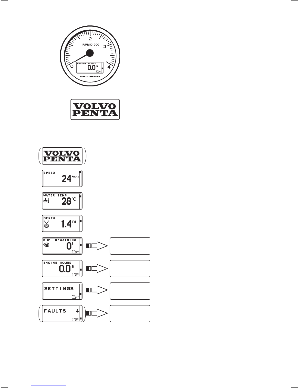
EVC System Tachometer
Introduction
Volvo Penta EVC System Tachometer presents relevant boat and engine information to the helmsman. Information is presented on a display in the tachometer.
Information is depending on engine model, number of
sensors and type of accessories.
Using the instrument
Start-up screen
This is the start-up screen for the EVC System Tachometer. After a few seconds the first item in MAIN
MENU will appear.
Main menu
Navigating the menus
Navigate the menus by turning NAVIGATION WHEEL
clockwise or counter-clockwise. Views with a POINTING HAND-symbol indicates a SUB-MENU. To enter
a SUB-MENU, push NAVIGATION WHEEL.
Speed (Optional)
Boat speed. Requires multisensor or GPS.
Water temp (Optional)
Water temperature. Requires multisensor.
Depth (Optional)
Water depth. Requires multisensor.
Trip menu (Optional)
Shows trip information. Requires the following:
- Multisensor or NMEA 0183/NMEA 2000 compatible
component (plotter, GPS, paddle wheel etc)
- Fuel level sender
- Trip computer software
Gauges menu
Shows data parameters.
Settings menu
The SETTINGS MENU allows the user to set various
options for the EVC System and to calibrate various
parameters.
Faults list
Number after word FAULTS indicates number of faults
stored in FAULTS LIST. List is reset when system is
rebooted.
NOTE! Faults list is not shown if no faults are registered.
Trip menu
Gauges menu
Settings menu
Faults list
27
Instruments
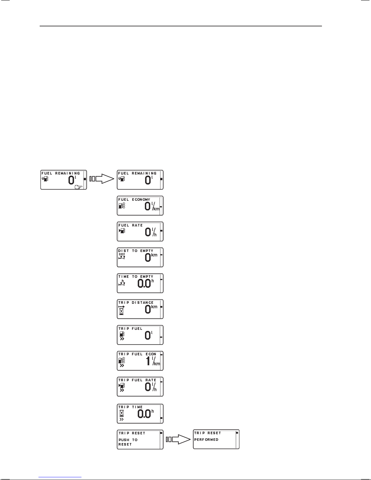
Trip menu (extra optional)
In the TRIP MENU the user gets trip information from the EVC System and the user is allowed to select which
view that should be presented in the EVC System Tachometers MAIN MENU as trip information. To get trip information following are required:
- Multisensor or NMEA 0183/NMEA 2000 compatible component (plotter, GPS, paddle wheel etc)
- Fuel level sender
- Trip computer software
NOTE! The accuracy of trip information concerning, and based on, remaining fuel volume depends on which
method the user has choosen for calibrating the fuel tank.
When in TRIP MENU, select view by turning NAVIGATION WHEEL. To select view as favorite, push NAVIGATION WHEEL. System returns to MAIN MENU.
Push BACK BUTTON to return to MAIN MENU without setting a new favorite.
Units are user selectable. See section "Units"
TRIP RESET: Reset all trip data.
FUEL REMAINING: Fuel remaining (l, Gal).
FUEL ECONOMY: Instantaneous fuel rate per dis-
tance (l/nm, l/km, l/mile, Gal/nm, Gal/km, Gal/mile).
FUEL RATE: Instantaneous fuel rate per hour (l/h,
Gal/h).
DISTANCE TO EMPTY: Distance to empty based on
instantaneous fuel rate, remaining fuel and speed
(nm, km, miles).
TIME TO EMPTY: Time to empty based on instantaneous fuel rate and remaining fuel (h).
TRIP DISTANCE: Trip distance since last reset (nm,
km, miles).
TRIP FUEL: Trip fuel used since last reset (l, Gal).
TRIP FUEL ECONOMY: Average fuel rate per dis-
tance since last reset (l/nm, l/km, l/mile, Gal/nm, Gal/
km, Gal/mile).
TRIP FUEL RATE: Average fuel rate per hour since
last reset (l/h, Gal/h).
TRIP TIME: Trip engine hours since last reset (h).
Trip menu structure
28
Instruments
 Loading...