

Page 1

OPERATOR’S MANUAL
Plus d'informations sur : www.dbmoteurs.fr
D25A MS/MT
D30A MS/MT
Page 2

CALIFORNIA
Plus d'informations sur : www.dbmoteurs.fr
Proposition 65 Warning
Diesel engine exhaust and some of its constituents are known
to the State of California to cause cancer, birth defects, and
other reproductive harm.
Page 3

Foreword
Plus d'informations sur : www.dbmoteurs.fr
Thank you for purchasing this Volvo Penta diesel engine.
This manual contains operation instructions and maintenance and inspection information. In order to ensure safety and bring out the maximum performance of the engine, do not operate the
engine until you have read and fully understood the contents of this manual. Do not hesitate to
consult your Volvo Penta dealer.
Failure to follow the instructions and cautions in this manual may result in serious accidents.
* Keep this manual at hand for easy reference.
* If this manual is damaged or misplaced, immediately order a new copy from your dealer.
Page 4

Contents
Plus d'informations sur : www.dbmoteurs.fr
Foreword .................................................................. 3
Safety Information ................................................... 6
Safety regulations during engine operation ............. 7
Safety directions for maintenance and service ....... 8
Warning labels D25A / D30A MS ......................... 10
Warning labels D25A / D30A MT .......................... 11
Introduction ............................................................ 12
Care of the environment ....................................... 12
Fuel and oil .......................................................... 12
Service and spare parts ....................................... 12
Certified engines .................................................. 13
Warranty .............................................................. 13
Presentation ........................................................... 14
D25A/D30A MS ................................................... 14
D25A/D30A MT .................................................... 15
New Engine Initial service ...................................... 16
General ................................................................ 16
External Inspection .............................................. 16
Valves and Plugs ................................................. 16
Electrical Wiring ................................................... 16
Fill Fuel system ................................................... 16
Fill Lubrication system ......................................... 16
Fill Cooling system .............................................. 16
Starting .................................................................. 17
Before starting ..................................................... 17
Warming-up .......................................................... 17
Standard control system ........................................ 18
Instrument panels ................................................ 18
Warning displays .................................................. 19
After an alarm ...................................................... 19
Alarm test ............................................................ 19
Starting switch ..................................................... 19
Starting procedure ................................................ 20
Operation ............................................................. 21
Alarms and fault indication ................................... 22
Stopping the engine ............................................. 22
Emergency stop ................................................... 22
Operation ............................................................... 23
General ................................................................ 23
Applying Load ...................................................... 24
Running in ............................................................ 24
Forced propeller rotation ....................................... 24
Manoeuvring ........................................................ 24
Manual speed control ........................................... 25
Start using auxiliary batteries ............................... 27
Stopping ................................................................ 28
Manual Stop Lever ............................................... 28
After stopping ........................................................ 29
General ................................................................ 29
Anti-freezing measures ........................................ 29
Breaks in operation [not using the engine]............ 29
Maintenance .......................................................... 30
Maintnenance schedule D25A/D30A MS .............. 31
Maintnenance schedule D25A/D30A MT .............. 34
Overhaul information ............................................ 37
Recommendation of Daily Operation Records ...... 39
Engine ................................................................... 40
Valve Clearance ................................................... 40
Firing order ........................................................... 41
Vibration Damper Inspection ................................ 42
Re-tighten Bolts and Nuts .................................... 42
How to use the Turning Gear ............................... 43
Fuel system ........................................................... 44
Fuel system bleeding ........................................... 44
Fuel filter change ................................................. 46
Fuel tank drain ..................................................... 47
Fuel injection nozzle tip change ........................... 47
Fuel injection pressure ......................................... 48
Injection timing inspection .................................... 50
Fuel control .......................................................... 51
Twin fuel pre-filter/water separator ........................ 52
Lubrication system ................................................. 54
Lubrication oil level check .................................... 54
Lubrication oil filling .............................................. 54
Lubrication oil change .......................................... 56
Oil filter change .................................................... 57
Lubrication oil by-pass filter change ..................... 58
Hydraulic governor oil filter change ....................... 58
Freshwater system ................................................ 59
Coolant level check .............................................. 59
Coolant filling ....................................................... 60
Coolant drain ........................................................ 60
Freshwater system flushing ................................. 61
Seawater system ................................................... 62
Draining the seawater system .............................. 62
Check and Change the zinc anodes ..................... 62
Seawater filter check/change ............................... 62
Seawater pump impeller check/hange .................. 63
Heat exchanger cleaning ...................................... 63
4
Page 5

Air Inlet and Exhaust Systems .............................. 64
Plus d'informations sur : www.dbmoteurs.fr
Turbocharger Inspection ....................................... 64
Cleaning the Air Cooler ........................................ 64
Check air cooler drain pipe ................................... 64
Wash the air filter ................................................. 65
Electrical system ................................................... 66
Protective Devices Inspection.............................. 66
Check the electrical wiring ................................... 66
Starter motor inspection ....................................... 66
Alternator Inspection ............................................ 66
Drive belts. Check/Adjust/Change ........................ 66
Inhibiting ................................................................ 67
General ................................................................ 67
Preparation .......................................................... 67
Care during storage .............................................. 67
Return the engine to service ................................ 67
Storage of Engine in operating condition .............. 68
Troubleshooting ..................................................... 69
Technical Data ....................................................... 70
D25A MS ............................................................. 70
D25A MT ............................................................. 71
D30A MS ............................................................. 72
D30A MT ............................................................. 73
Fuel specification ................................................. 74
Lubrication oil specification .................................. 75
Coolant specification ............................................ 76
Tightening Torque Tables ..................................... 77
Identification numbers D25A / D30A .................... 83
Sea trial data ....................................................... 84
5
Page 6
Safety Information
Plus d'informations sur : www.dbmoteurs.fr
Read this chapter thoroughly. It concerns your safety. This section describes how safety information is presented
in this manual and on the product. It also includes a summary of basic safety regulations for operation and maintenance of the engine.
Make sure you are in possession of the right operator’s manual before reading on. If this is not the case,
please get in touch with your Volvo Penta dealer.
If operations are performed incorrectly it could result in personal injury or damage to property or the engine. Read the Operator’s Manual carefully before operating or servicing the engine. If anything is unclear
please contact your Volvo Penta dealer for assistance.
This symbol is used in the book and on the engine to make you aware of safety infor-
mation. Always read these safety precautions very carefully.
In the Operator’s Manual warning texts have the following priority:
WARNING! If these instructions are not followed there is a danger of personal injury,
extensive damage to the product or serious mechanical malfunction.
IMPORTANT! Used to draw your attention to something that can cause damage,
product malfunction or damage to property.
NOTE! Used to draw your attention to important information that will facilitate work or
operations.
This symbol is used in certain cases on our products and refers to important information in the Operator’s Manual. Ensure that warning and information symbols on the engine
and transmission are always visible and legible. Replace symbols that have been damaged
or painted over.
6
Page 7

Safety regulations during engine operation
Plus d'informations sur : www.dbmoteurs.fr
Safety information
The new engine
Read instruction manuals and other information accompanying the new vessel thoroughly. Accustom
yourself with handling the engine, controls and other
equipment in a safe and correct manner.
Remember that when operating a vessel, you have a
legal responsibility to be aware of and follow regulations concerning traffic and safety at sea. Inform yourself of the regulations applicable to your vessel and
the waters your in by getting in touch with the relevant
authorities or marine safety organization.
Accidents and other incidents
Sea rescue statistics show that deficient maintenance
of vessels and engines together with defective safety
equipment often causes accidents and other incidents
at sea.
Make sure your vessel and engine are maintained in
accordance with directions in the instruction manuals
and that the safety equipment on board is in good
working order.
Daily inspection
Make a habit of visually inspecting the engine and
engine room before starting and after stopping the
engine. This will help you to quickly detect any fuel,
coolant or oil leaks and any other abnormalities that
have occurred or are about to occur.
Maneuvering
Avoid violent and rapid rudder movement and gear
shifting. There is a risk of the passengers falling down
or falling overboard. A rotating propeller can cause serious injury. Make sure there is nobody in the water
before engaging forward/reverse. Never run close to
bathers or in places where you have reason to
believe there are people in the water.
Filling fuel
There is a risk of fire and explosion when filling fuel.
Smoking is prohibited and the engine must be turned
off. Never overfill the tank. Close the filler cap
securely. Use only fuel recommended in the operators
manual. The incorrect grade of fuel can disturb operation or cause breakdown. This can also lead to the
control rod jamming on diesel engines, which will cause the engine to overspeed and risk damaging machinery and causing personal injury.
Combustible enviroment
Due to the risk of fire and/or explosion, do not start or
continue to run the engine if there is a suspected leak
or discharge of combustible media, e.g. fuel oil or
LPG, in the engine surroundings.
Carbon monoxide poisoning
When a vessel is moving forward, it will cause a certain vacuum to form behind the vessel. In unfortunate
circumstances, the suction from this vacuum can be
so great that the exhaust gases from the vessel are
drawn into the bridge or cabin and cause carbon monoxide poisoning. This problem is most prevalent on
high, wide vessels with abrupt stern. Other factors
that can increase the effect of the suction are wind
conditions, load distribution, swells, trim, open hatches and portholes, etc. Most modern vessels, however, are designed in such a way that this problem is
very rare. If suction should arise anyway, do not open
hatches or portholes at the fore of the vessel. Surprisingly, this will otherwise increase the suction. Try
changing speed, trim, or load distribution instead. Get
in touch with your Volvo Penta dealer for help in obtaining the best solution for your vessel.
7
Page 8

Safety information
Plus d'informations sur : www.dbmoteurs.fr
Safety directions for maintenance and service
Preparations
Knowledge
The operator’s manual contains directions for performing normal maintenance and service in a safe and
correct manner. Read the directions carefully before
starting work. More detailed service literature is available from your Volvo Penta dealer. Never perform a
task unless you are absolutely sure how it is to be
carried out; call your Volvo Penta dealer for assistance instead.
Stop the engine
Stop the engine before opening or dismantling the
engine hatch/hood. Maintenance and service must be
carried out with the engine stationary unless stated
otherwise in the instructions. Prevent inadvertent start
of the engine by removing the starter key and turning
off the power with the main switch, locking it in the off
position. Place warning signs stating that service is in
progress in every position from which the engine can
be started. Working on or approaching a running engine is a safety hazard. Loose clothing, hair, fingers or
a dropped tool can be caught in rotating parts and
cause serious bodily injury. Volvo Penta recommend
leaving all work requiring the engine to be running to
an authorized Volvo Penta dealer.
Lifting the engine
Always use the lifting eyes mounted on the engine
when lifting the engine. Always make sure lifting
equipment is in good condition and constructed for the
lift (engine weight together with possible reverse gear
and extra equipment). Use an adjustable lifting boom
to ensure safe handling when lifting the engine. All
chains and wires must run parallel with each other and
as much at right angle as possible to the top of the
engine. Note that any extra equipment mounted on the
engine can change the center of gravity. Special lifting
devices may be required to obtain the right balance
and safe handling. Never perform service on an engine suspended only from a lifting device.
IMPORTANT! Engine must only be lifted
horizontally.
IMPORTANT! Engine lifting eyes are designed
only for lifting an engine. Do not use the engine
lifting eyes when lifting a complete genset or an
engine with a gearbox mounted.
Before starting
Refit all guards and covers that have been removed
before starting the engine. Make sure there are no
tools or other objects left on the engine. A turbocharged engine must never be started without the air filter
fitted. The rotating compressor wheel in the turbocharger can cause severe personal injury.
There is also a risk of foreign objects being drawn in
and causing mechanical damage.
Fire and explosion
Fuel and lubricants
All fuels, most lubricants, and many chemicals are
flammable substances. Always read and follow the
directions on the packaging. Work performed on the
fuel system must be done on a cold engine. Fuel
leaks and spills on hot surfaces or electrical
components can cause fires.
Keep oil- and fuel drenched rags and other hazardous
materials where they are safe in case of fire. Oil drenched rags can selfignite in certain conditions. Never
smoke when refueling, topping up with oil or when in
the vicinity of the fuel station or the engine room.
Non-original parts
Components in fuel, lubrication, ignition and electrical
systems on Volvo Penta engines are designed and
manufactured to minimize the risk of explosion and
fire in compliance with existing legislation.
The use of non-original parts can result in explosion
or fire.
Batteries
Batteries contain and generate oxyhydrogen gas,
especially when charging. Oxyhydrogen is easily
ignited and extremely explosive. Smoking, open flames and sparks must never occur in, or close to, the
batteries or battery compartment. A faulty battery connection or jumper cable can generate sparks that can
cause the battery to explode.
Start spray
Never use start spray or similar start help. Explosions
can occur in the intake manifold. Risk for personal
injury.
8
Page 9

Safety information
Plus d'informations sur : www.dbmoteurs.fr
Hot surfaces and fluids
At operating temperature, the engine and its components are hot. A hot engine always involves risk for
burn injuries. Take care with hot surfaces. E.g.: exhaust manifold, turbocharger, oil pan, charge air pipe,
starting heater, hot coolant and warm lubricant in pipes and hoses.
WARNING! Do not open the crankcase
covers while the engine is still hot.
Carbon monoxide poisoning
Start the engine in well-ventilated spaces only. When
running in confined spaces, the exhaust gases and
crankcase gases must be evacuated.
Chemicals
Most chemicals such as glycol, anti-corrosion agent,
preservatives, degreasing agent, etc., are hazardous
to health. Always read and follow the directions on
the packaging.
Certain chemicals such as preservatives are
flammable and harmful to inhale. Provide good
ventilation and use breathing protection when
spraying. Always read and follow the directions on the
packaging. Store chemicals and other hazardous
materials out of reach of children. Leave left over or
used chemicals to a destruction plant.
Always cover any electric component if it is located
under the fuel filter. Otherwise it might be damaged by
fuel spills.
Electrical system
Turn off the power before commencing work on the
electrical system, the engine must be stopped and the
powered turned off with the main switch/switches.
Shore power to the engine heater, battery charger or
other extra equipment fitted to the engine must be disconnected.
Batteries
Batteries contain a highly corrosive electrolyte. Protect your eyes, skin and clothing when charging and
handing batteries. Always use protective goggles and
gloves.
In case of splashes on the skin, wash with soap and
plenty of water. In case of splashes in the eyes, rinse
immediately with plenty of water and call a doctor.
Avoid burns and crushing or cutting!
At operating temperature, the engine coolant is hot
and under pressure. Steam can cause personal
injury. Check the coolant level only after the engine
has been stopped and the coolant filler cap has cooled enough to touch with your hand. Never adjust the
V-belts while the engine is running.
Cooling system
There is a risk of water entering when working on the
seawater system. Therefore, stop the engine and
close the seawater cock before starting work.
Avoid opening the coolant filler cap when the engine is
warm. Steam or hot coolant may spurt out and cause
burn injuries.
If the filler cap, coolant pipe, cock, etc., must
nevertheless be opened or dismantled while the
engine is warm, the filler cap must be opened
carefully to release the pressure before removing it
completely and starting work. Note that the coolant
can still be hot and cause burn injuries.
Lubricating system
Hot oil can cause burn injuries. Avoid skin contact
with warm oil. Make sure the lubricating system is
depressurized before starting work. Never start or run
the engine with the oil filler cap removed or there will
be a risk of the oil being thrown out.
Fuel system
Always protect your hands when carrying out leak detection.
Service batteries carefully!
If you spill electrolyte on yourself, flush skin immediately with lots of water. Apply baking soda to help neutralize the acid. If electrolyte gets in your eyes, rinse
immediately with large amounts of water then contact
a doctor at once.
Handle antifreeze carefully!
Antifreeze contains alkali. Avoid contact with skin
and eyes to prevent personal injury. Dispose of
drained antifreeze coolant according to local
regulations. For disposal, consult your dealer.
Dress properly for the job!
Wear protective devices - hard hat, face shield, safety
shoes, goggles, heavy gloves, ear protectors, etc. for your own safety.
Recommended fuel, lubrication oil and coolant!
Use of any other fuel oil, lurication oil or coolant than
the recommended can cause engine damage and reduce engine service life.
Perform all recommended inspections!
Perform pre-start inspection and periodic inspection
on items listed in this manual. Failure to follow this
recommendation can cause serious engine damage.
Escaping fluids under pressure can pierce bodily tissue and cause serious injury. Risk of blood poisoning.
9
Page 10
Safety information
Plus d'informations sur : www.dbmoteurs.fr
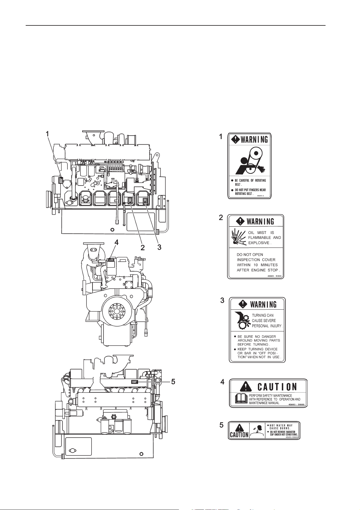
Warning labels D25A / D30A MS
The engine carries ‘Warning Labels’ at places where you are required to pay special attention. Please read them
carefully and make sure you understand the content of each label and the meaning of their position.
1. Make sure the labels are legible. If you find any letter or picture illegible in a label, remove soil from the label,
or replace it.
2. Clean the label with cloth and water or cleanser. Do not use organic solvent or gasoline, this would dissolve
the label’s adhesive and cause the label to fall off.
3. If any label is damaged, lost or illegible, replace it. When replacing a label, make sure the new label is
identical to the old one. For new labels, please contact your dealer.
10
Page 11

Safety information
Plus d'informations sur : www.dbmoteurs.fr
Warning labels D25A / D30A MT
The engine carries ‘Warning Labels’ at places where you are required to pay special attention. Please read them
carefully and make sure you understand the content of each label and the meaning of their position.
1. Make sure the labels are legible. If you find any letter or picture illegible in a label, remove soil from the label,
or replace it.
2. Clean the label with cloth and water or cleanser. Do not use organic solvent or gasoline, this would dissolve
the label’s adhesive and cause the label to fall off.
3. If any label is damaged, lost or illegible, replace it. When replacing a label, make sure the new label is
identical to the old one. For new labels, please contact your dealer.
11
Page 12

Introduction
Plus d'informations sur : www.dbmoteurs.fr
This operator’s manual has been produced to give you the greatest benefit of your Volvo Penta marine engine. It
contains the information necessary to handle and maintain your engine in a safe and correct manner. We would
like you to read this operator’s manual thoroughly and learn how to handle the engine, controls and other equipment in a safe manner before starting to operate the engine.
Keep the operator’s manual within reach at all times.
Care of the environment
We would all like to live in a clean and healthy environment. An environment where we can breathe clean air, see healthy trees, have clean water in our lakes and oceans, and are able to enjoy the sunshine
without being worried about our health. Unfortunately,
this cannot be taken for granted nowadays but is something we must work together to achieve.
As a manufacturer of marine engines, Volvo Penta
has a special responsibility, why care of the environment is a core value in our product development. Today, Volvo Penta has a broad range of engines where
progress has been made in reducing exhaust emissions, fuel consumption, engine noise, etc. We hope
you will take care in preserving these qualities.
Always follow any advice given in the operator’s manual concerning fuel grades, operation and maintenance and you will avoid causing unnecessary interference to the environment. Get in touch with your
Volvo Penta dealer if you notice any changes such as
increased fuel consumption exhaust smoke.
Adapt speed and distance to avoid wash and noise
disturbing or injuring animal life, moored boats, jetties,
etc. Leave islands and harbours in the same condition as you want to find them. Remember to always
leave hazardous waste such as waste oil, coolant,
paint and wash residue, flat batteries, etc., for disposal at a destruction plant. Our joint efforts will make a
valuable contribution to our environment.
Fuel and oil
Use only fuel and lubrication oil grades recommended
in the technical data section of this Operator’s Manual. Other grades can cause operational problems, increase fuel consumption and have long-range effects
on engine service life.
Service and spare parts
Volvo Penta marine engines are designed for high
operational reliability and long service life. They are
constructed to withstand the marine environment while affecting it as little as possible. Through regular
service and the use of Volvo Penta original spare
parts, these qualities will be retained.
The worldwide Volvo Penta network of authorized
dealers is at your service. They are specialists in
Volvo Penta products and stock accessories, original
spare parts, test equipment and the special tools required to perform high-quality service and repairs.
Always follow the maintenance intervals specified in
the operator’s manual and remember to specify the
engine number when ordering service and spare
parts.
12
Page 13

Introduction
Plus d'informations sur : www.dbmoteurs.fr
Certified engines
It is essential that owners and operators of emission certified engines, used in areas where exhaust emissions
are regulated by law, are aware of the following points:
A certification involves the engine type being checked and approved by applicable authorities. Engine manufacturers guarantee that all engines of the same type correspond with the certified engine.
This puts special demands on the maintenance and service of your engine:
* Maintenance and service intervals recommended by Volvo Penta must be followed.
* Only Volvo Penta original spare parts may be used.
* Service of injector pumps, pump settings and injectors must always be performed by an authorized Volvo
Penta service person.
* The engine must not be modified in any way with the exception of accessories and service kits approved by
Volvo Penta for use on the engine.
* Installation modifications must not be made to the engine exhaust pipe or inlet channels.
* Sealed sections must not be broken by anyone other than authorized personnel.
Otherwise, general directions concerning running, care and maintenance given in the operator’s manual apply.
IMPORTANT! Neglected or deficient maintenance/service and the use of non-original spare parts will
entail Volvo Penta renouncing any responsibility for the engine corresponding to the certified version.
Volvo Penta will not compensate for damage and/or costs arising from the above.
Warranty
Your new Volvo Penta marine engine is covered by a limited warranty complying with the conditions and instructions given in the Warranty and Service Book.
Note that AB Volvo Penta’s responsibility is limited to what is specified in the Warranty and Service Book. Read it
carefully as soon as possible after delivery. It contains important information concerning the warranty card, service, maintenance and what the owner is responsible to be aware of, check and perform. AB Volvo Penta will otherwise decline warranty liability completely or fully.
Get in touch with your Volvo Penta dealer if you have not received a Warranty and Service Book or a
copy of the warranty card.
13
Page 14
Presentation
Plus d'informations sur : www.dbmoteurs.fr
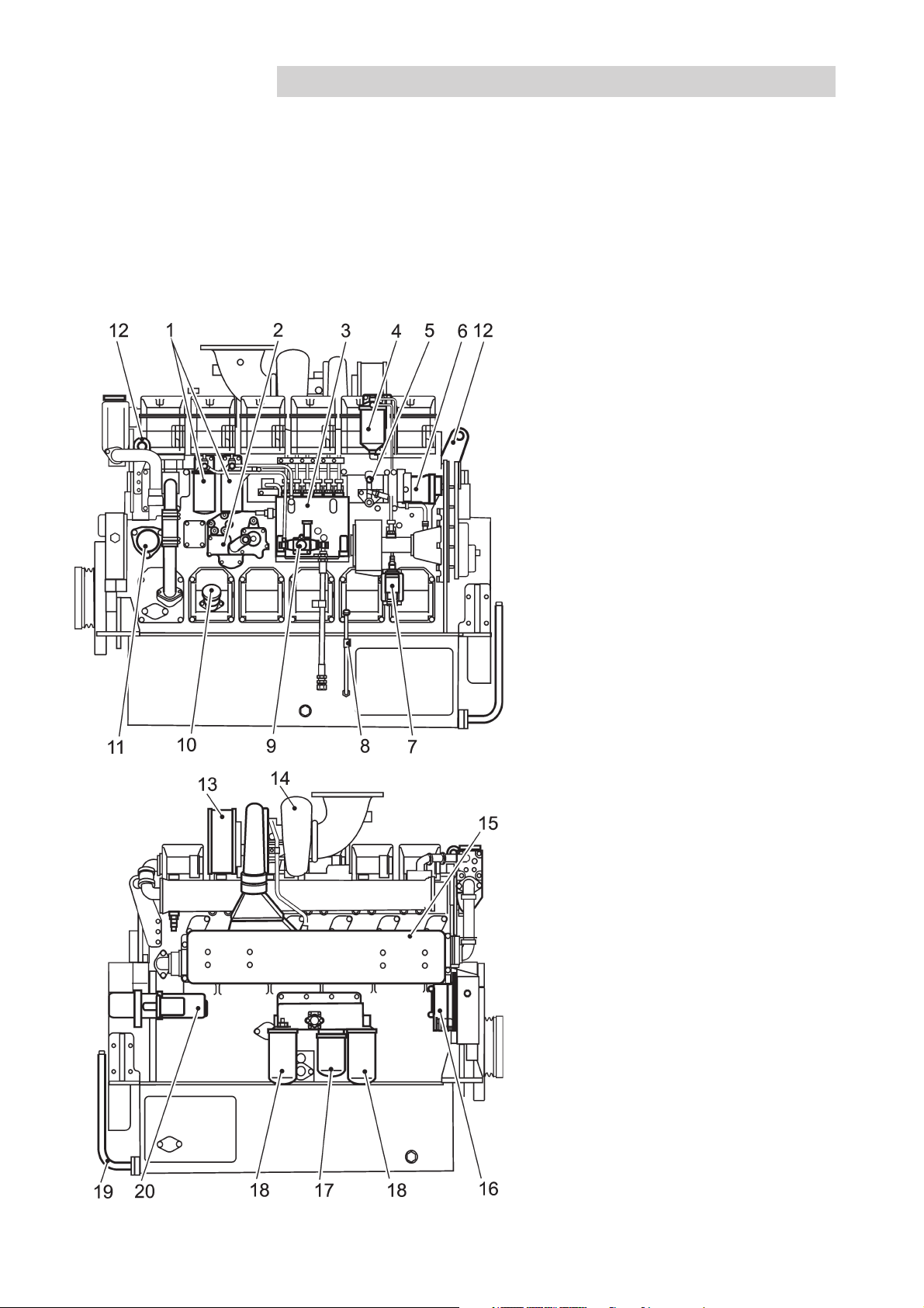
D25A/D30A MS
The D25A and D30A are in-line, direct injection, 6-cylinder, 4-stroke marine diesel engines. They are equipped
with turbocharger and fitted with either a heat exchanger for thermostat-regulated freshwater cooling or connections for keel cooling.
An optimal combination of combustion chambers, fuel injection system, effective turbocharger and charge air
cooling, provide excellent fuel consumption over the whole range of engine speeds where the engine is economical in operation.
D25A/D30A MS
1. Fuel filters
2. Oil cooler
3. Fuel injection pump
4. Governor oil filter
5. Manual stop lever
6. Governor
7. Stop solenoid
8. Oil dipstick
9. Fuel feed pump
10. Oil filler cap
11. Fresh water pump
12. Lifting eye
13. Intake air silencer
14. Turbocharger
15. Charge air cooler
16. Alternator
17. By-pass filter for engine oil
18. Oil filters
19. Engine oil drain pipe
20. Starter motor
14
Page 15
Presentation
Plus d'informations sur : www.dbmoteurs.fr
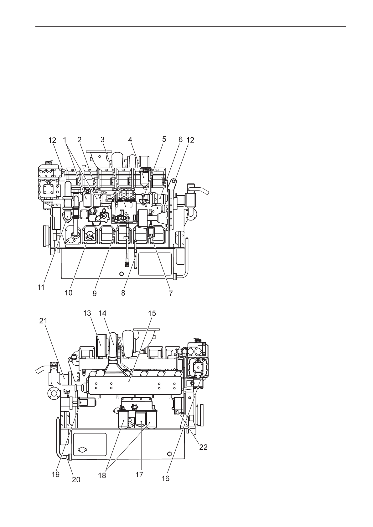
D25A/D30A MT
The D25A and D30A are in-line, direct injection, 6-cylinder, 4-stroke marine diesel engines. They are equipped
with turbocharger and fitted with either a heat exchanger for thermostat-regulated freshwater cooling or connections for keel cooling.
An optimal combination of combustion chambers, fuel injection system, effective turbocharger and charge air
cooling, provide excellent fuel consumption over the whole range of engine speeds where the engine is economical in operation.
D25A/D30A MT
1. Fuel filters
2. Oil cooler
3. Fuel injection pump
4. Governor oil filter
5. Manual stop lever
6. Governor
7. Stop solenoid
8. Oil dipstick
9. Fuel feed pump
10. Oil filler cap
11. Fresh water pump
12. Lifting eye
13. Intake air silencer
14. Turbocharger
15. Charge air cooler
16. Heat exchanger
17. By-pass filter for engine oil
18. Oil filters
19. Starter motor
20. Engine oil drain pipe
21. Sea water pump
22. Alternator
15
Page 16

New Engine Initial service
Plus d'informations sur : www.dbmoteurs.fr
General
Before starting a new or reconditioned engine for the first time, give it an initial inspection. This to guarantee your
own safety as well as the maximum service life of the engine.
External Inspection
1. Check the engine control system for loose terminals.
2. Check defects of engine parts.
3. Check the following components for loose bolts or
nuts:
* Plugs and covers of fuel, lubrication and cooling
system
* Coupling of fuel injection pump and shaft
* Crankshaft pulley and vibration damper
* Mounting brackets
* Fuel control linkage
* Turbocharger
* Timing gear case
* Exhaust manifolds
* Cylinder heads
* Air-duct connection-hose clamp
4. Check for Fuel, Oil, Coolant and Air leaks and repair if needed.
Electrical Wiring
Check for loose or damaged electrical wiring around
the engine and if necessary firmly reconnect to terminals or cable-joint portions. Damaged cables must
be replaced.
If your engine is reconditioned, make sure the wiring
is according to the drawings.
Fill Fuel system
Refer to chapter maintenance fuel system.
Fill Lubrication system
Refer to chapter maintenance lubrication system.
Fill Cooling system
Refer to chapter maintenance cooling system.
5. Make commissioning report for new or overhauled
engine.
IMPORTANT! All covers must be mounted before
attempting to start your engine.
Valves and Plugs
Make sure the following valves and plugs are open or
closed properly:
Fuel supply valve Open
Coolant drain cock (engine) Closed
Coolant drain cock (water pump) Closed
Coolant drain cock (heat exchanger) Closed
IMPORTANT! If the coolant drain cocks are not
closed the coolant will drain from the engine and
this may cause severe damage to the engine.
16
Page 17

Starting
Plus d'informations sur : www.dbmoteurs.fr
Before starting
WARNING! Before starting the engine make sure that neither people, nor tools, are in contact with
moving parts of the engine. Notify the people in the vicinity of the engine when starting it.
WARNING! Make sure that you know how to stop the engine before you start it (in case of emergency).
If you are starting the engine for the first time, have someone stand-by at the emergency stop lever to
stop the engine in case abnormal noise occurs during start up. Block air intake in case of stop lever
malfunction, this has to be prepared in advance.
WARNING! Make sure that the manual speed control knob is locked in neutral position before starting
the engine (refer to page 26 of this manual).
IMPORTANT! If the starter motor has been engaged for the maximum time (30 seconds), it must be
allowed to cool down for at least one minute before a new attempt is made at starting.
Warming-up
WARNING! Do not conduct warm-up operation for an extended period of time. Prolonged warm-up
operation causes carbon buildup in the cylinders that leads to inperfect combustion.
* Operate at low idle speed for 5 to 10 minutes to warm up the engine.
* The oil pressure will be 0.20 to 0.29 MPa [28 to 43 psi] after the warm-up run. If the engine speed is increased
immediately after start-up, the oil pressure, due to cold lubrication oil and therefore higher viscosity, will exceed the normal level - 0.49 to 0.64 MPa [71 to 92 psi] (at rated speed) but it will normalize with increasing oil
temperature.
* If the Lubrication oil pressure does not increase when you have started the engine, immediately stop the engi-
ne and do not restart until the problem has been fixed.
* Make sure that the cooling water flow is sufficient.
* Make sure there is enough fuel aboard the vessel for the planned duration of operation.
17
Page 18
Standard control system
Plus d'informations sur : www.dbmoteurs.fr
This chapter describes the standard Volvo Penta instruments that are available for your engine. Note that that
tachometer, oil gauge, temperature gauge, charge gauge, starting switch, etc., that are shown here as panel
mounted, in some cases may be mounted separately.
If the vessel is equipped with instruments not described here and you are not sure of their function, please get in
touch with the shipyard or the company that installed the installation aboard the vessel.
IMPORTANT! Read the chapter “Starting” before starting your engine.
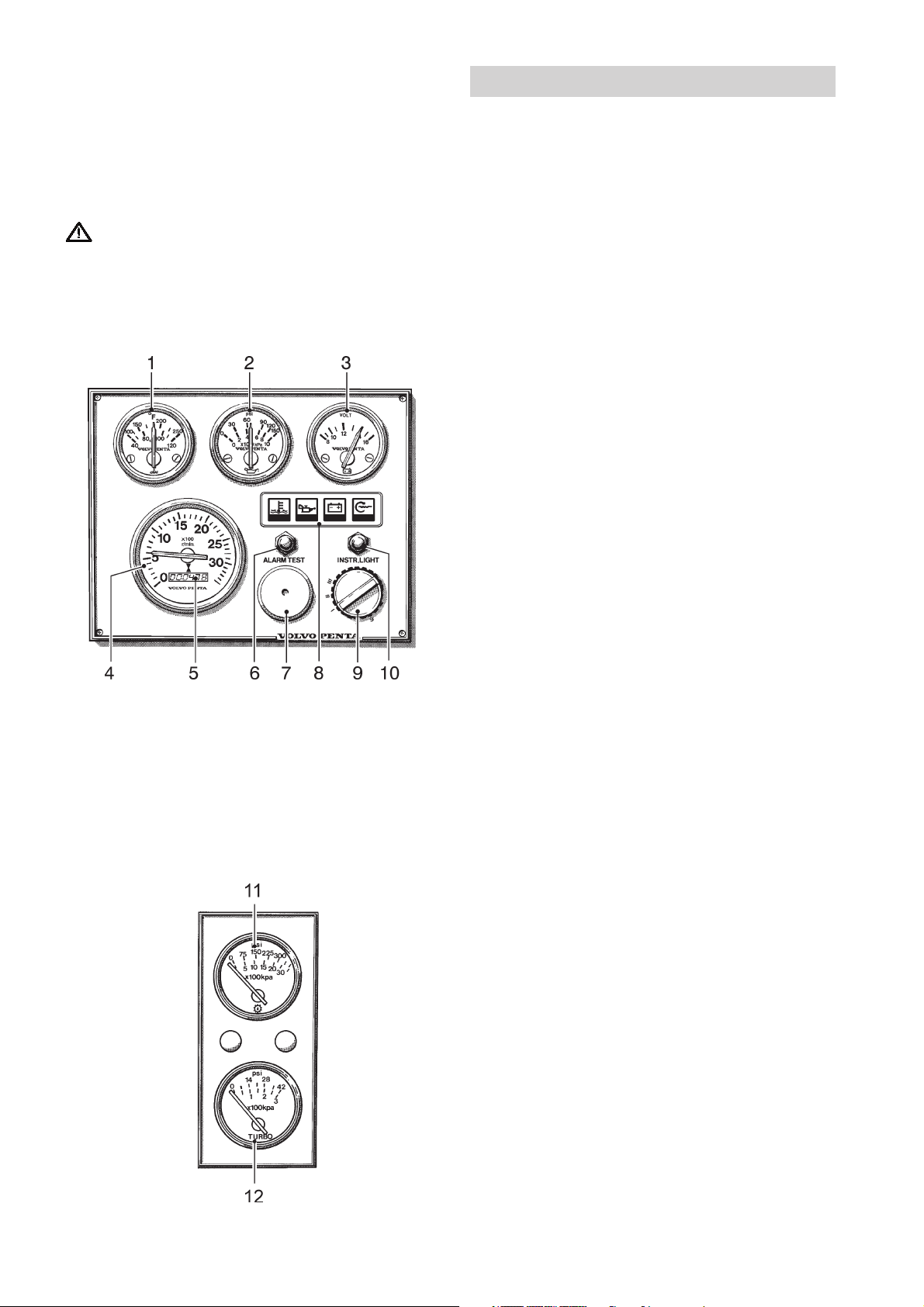
Instrument panels
Instrumentation for the main control position and auxiliary control position.
1. Temperature gauge. Indicates the engine coolant
temperature.
2. Oil pressure gauge. Indicates the pressure of the
engine lubricant.
3. Voltmeter. Indicates the charge voltage from the
generator when the engine is running and the battery voltage when the engine is stopped.
4. Tachometer. Indicates the speed of the engine in
rpm.
5. Hour counter. Shows the total number of engine
running hours as a decimal number.
6. Press button for testing and acknowledging
alarms (see next page “Warning displays”).
7. Siren for acoustic alarm that sounds if one of the
warning lamps comes on.
8. Warning display (see section “Warning displays”,
pos 1–3).
9. Starting switch (see next page).
10. Press button for instrument illumination.
11. Oil pressure gauge. Indicates the oil pressure in
the reverse gear.
12. Charge air pressure gauge. Indicates the turbocharger boost pressure.
18
Page 19
Standard Control System
Plus d'informations sur : www.dbmoteurs.fr
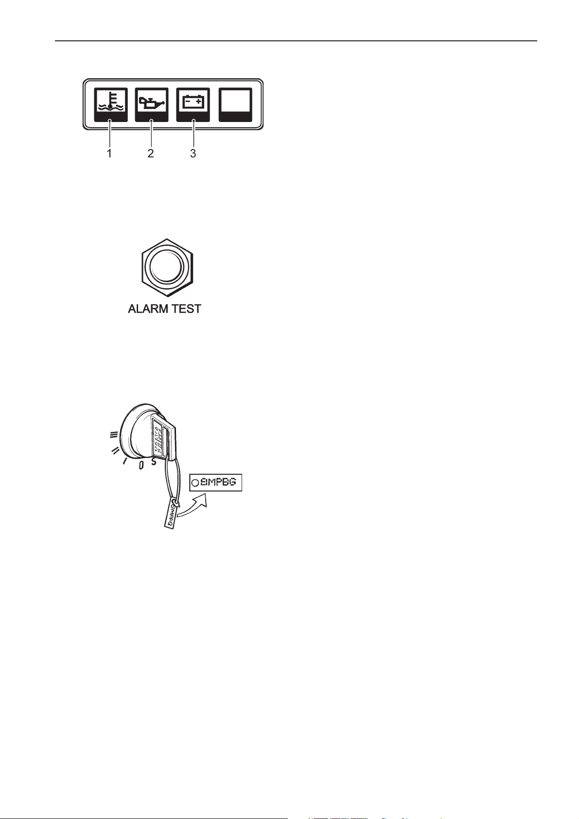
Warning displays
If the acoustic alarm sounds, one of the warning display lamps will immediately start to flash to indicate
the cause of the alarm.
1. Coolant temperature too high.
2. Lubricant pressure too low.
3. Generator not charging
After an alarm
Press the “Alarm test” button to acknowledge and
terminate the acoustic alarm. The relevant warning
lamp will continue to flash until the fault has been rectified.
Alarm test
After pressing the “Alarm test” button, the warning
lamps will come on and the acoustic alarm will start to
sound. Make a habit of always performing an alarm
test before starting.
Starting switch
Together with the starter keys a plate containing the
key code is delivered. This code is required when
ordering additional starter keys. Keep the code in a
safe place.
S = Stop position.
0 = Key can be inserted and removed.
I = Voltage on (drive position).
II = Not used
III = Start position.
19
Page 20
Standard Control System
Plus d'informations sur : www.dbmoteurs.fr
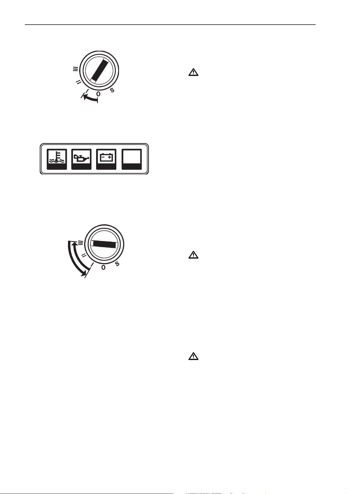
Starting procedure
1. Disengage the reverse gear and make sure the
turning gear is not engaged. Put the control lever
into neutral and idle on all control positions
WARNING! If the vessel is equipped with
controls that allow starting the engine in
gear, it is essential to check all control
positions to make sure a gear is not
engaged.
2. Turn on the power by putting the starter key in position “I”.
3. Check warning lamps and alarms. Press the
“Alarm test” button on the instrument panel to
make sure the warning lamps come on and the
acoustic alarm sounds.
4. Start the engine. Start using the starting switch.
Turn the key to position “III”. Release the key so
that it returns to “I” immediately after the engine
has started.
IMPORTANT! If the starter motor has been
engaged for the maximum time (30
seconds), it must be allowed to cool down for
at least one minute before a new attempt is
made at starting.
NOTE! The key must first be turned to “S” before making a new attempt at starting.
5. Check the instruments and run the engine
warm. Let the engine idle for the first ten seconds
and make sure the instruments and warning display show normal values. Then run the engine at
low speed and low load so it attains normal operating temperature before using full power.
IMPORTANT! Do not race the engine when it
is cold.
20
Page 21

Standard Control System
Plus d'informations sur : www.dbmoteurs.fr
Operation
Learn how to handle the engine, controls and other equipment in a safe and correct manner before taking it into
operation.
Check the instruments
Check the instruments and warning display directly after
start and regularly during operation.
Oil pressure
During operation, the oil pressure gauge should show a reading of 0,50 - 0,64 MPa (71 - 93 psi). A lower value is normal at idling speed. The acoustic alarm will sound automatically in case of low oil pressure.
Coolant temperature
During operation, the temperature gauge should show a reading of 71–85°C (160–185°F). The acoustic alarm will
sound automatically in case the coolant temperature is too
high.
Charging
During operation, the charge voltage gauge should show a
reading of 28V. The acoustic alarm will sound automatically
in case the charge voltage is missing.
21
Page 22
Standard Control System
Plus d'informations sur : www.dbmoteurs.fr
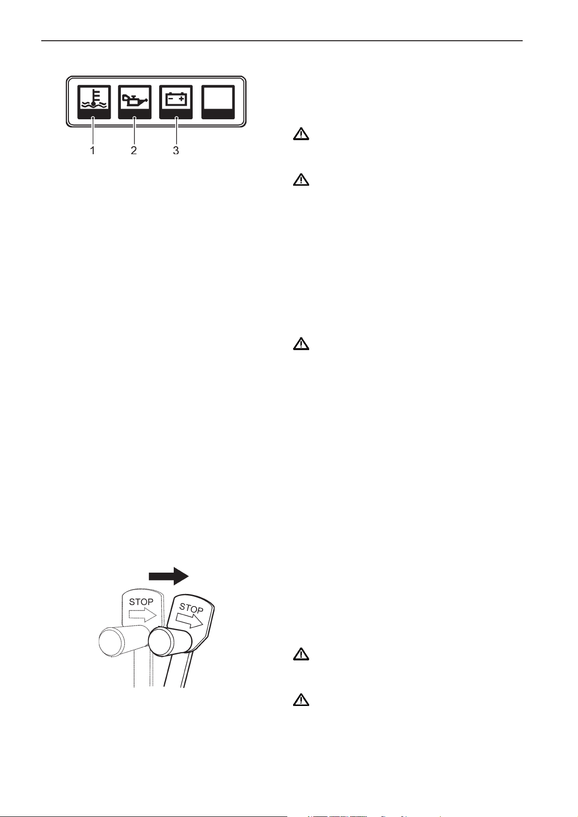
Alarms and fault indication
If the acoustic alarm sounds, one of the warning display lamps will immediately start to flash to indicate
the cause of the alarm: High coolant temperature (1),
low oil pressure (2) and no charge voltage (3).
IMPORTANT! Stop the engine immediately after
an alarm for low oil pressure. Investigate the
cause and rectify it.
IMPORTANT! Slow the engine speed to idle/
disengaged after an alarm for high coolant
temperature. If temperature does not drop, the
engine must be stopped. Investigate the cause
and rectify it.
Stopping the engine
Let the engine run at low idling speed (in neutral) for at
least three minutes before turning it off. This will keep
the engine temperature in balance and prevent it boiling.
IMPORTANT! The procedure described above is
especially important if the engine has been run
hard and/or exerted to heavy loads.
Stop
1. Disengage the marine gear by moving the lever to
neutral position.
2. Turn the key to stop position “S”.
3. Hold the key in position until the engine has stopped (the key will return to “0” automatically when
released and can then be removed).
NOTE! The stop solenoid will be activated for
approximately 40 seconds after stopping the
engine, but the engine can be restarted at any
time.
Emergency stop
If a fault occurs that prevents the engine being stopped by the normal method, it can be stopped manually
using the lever mounted on the engine. Move the lever
in the direction of the arrow and hold it there until the
engine has stopped.
WARNING! Working on or approaching a running
engine is a safety hazard. Beware of rotating
parts and hot surfaces.
WARNING! Never try to increase engine rpm with
the emergency stop lever since this will make
the engine overspeed and this will damage the
engine.
22
Page 23

Operation
Plus d'informations sur : www.dbmoteurs.fr
General
Learn how to handle the engine, controls and other equipment in a safe and correct manner before starting the
engine
WARNING! Stay clear of all rotating and moving
parts during operation.
IMPORTANT! Always keep the engine room well
ventilated. Insufficient airsupply to the engine
means imperfect combustion and a loss of
power.
IMPORTANT! During the first 50 hours of operation, operate the engine under a lighter load and
lower speeds than normal for break-in. Proper
break-in contributes to maximum service life of
the engine.
IMPORTANT! Do not turn OFF the battery
switch when the engine is running since this may
damage the alternator.
WARNING! At operating temperature, the engine
and its components are hot. A hot engine always
involves risk for burn injuries. Take care with hot
surfaces. E.g.: exhaust manifold, turbocharger,
oil pan, charge air pipe, starting heater, hot
coolant and warm lubricant in pipes and hoses.
IMPORTANT! Avoid overloading. This can cause
incomplete fuel combustion often indicated by
black exhaust, high fuel consumption and carbon
deposits in combustion chambers, affecting
engine life.
IMPORTANT! Do not turn the starter switch key
to the START position when the engine is
running this may damage the starter.
23
Page 24

Operation
Plus d'informations sur : www.dbmoteurs.fr
Applying Load
When the engine has reached operation temperature,
bring the engine to operating speed and apply the load
gradually.
During load operation make sure that:
1. No engine related alarms occur.
2. There are no visible leaks of fuel, lube oil, coolant
or exhaust gas
3. No abnormal noise or vibrations occur.
4. The color of the exhaust gas is normal.
5. The breather mist is of normal quantity and color.
6. Instrument readings are the normal.*
*Oil pressure: 0,50 to 0,64 Mpa (71 to 92 psi) (at
rated speed)
*Coolant temperature: 71 to 85°C (165 to 185 °F)
Running in
The engine must be “run in” during the first 10
hours of operation as follows:
Run the engine under normal operation. Do not run it
at full power except for short periods. Never run the
engine for long periods at constant rpm during this
time. A high consumption of lubricant is normal during
the running in period. Therefore, check the oil level
more often than recommended. The prescribed warranty inspection “First Service Inspection” must be
carried out during this first period of operation. For
more information: See Warranty and Service Book.
Forced propeller rotation
When the vessel is towed or anchoring in strong currents, the propeller can make the propeller shaft rotate
even though the engine is stationary. This may damage the marine gear.
Manoeuvring
The marine gear must be engaged at low idling speed.
There must be a brief pause after engaging gear before increasing the engine speed. Wait for approximately
two seconds to ensure that the gear clutch has engaged properly.
IMPORTANT! If the vessel is equipped with two
engines equipped with wed exhaust systems,
they must both be running while in reverse or
there will be a risk of water entering the engine
(through the exhaust passage).
Pulling away
1. Move the lever from neutral to the engagement
position for the desired direction of travel.
2. Apply load accordingly.
Forward–Reverse
1. Slow the engine speed to idling and allow the vessel to loose most of its speed.
2. Move the lever to neutral.
3. Move the lever to reverse. Wait for approximately
two seconds and then increase the engine speed
gradually.
IMPORTANT! A direct forward–reverse maneuver
can damage the marine gear and engine. It is
therefore always necessary to stop with the lever
in neutral for a few seconds and allow the vessel
to loose most of its speed before engaging. If the
speed of the vessel is too high, there is a risk of
the propeller windmilling which might cause the
engine to stop and start rotating in the wrong
direction. This may cause serious engine
damage.
24
Page 25
Operation
Plus d'informations sur : www.dbmoteurs.fr
Manual speed control
Manual speed adjustment of the engine can be done
using the manual speed control knob.
1. Disconnect the control cable connected to the
remote speed adjustment.
2. Turn the Lock counterclockwise to unlock the manual speed adjustment knob.
3. By pushing the button and pulling the knob
towards you the engine speed will increase. By
bushing the knob towards the engine the engine
speed will decrease.
WARNING! When adjusting engine speed avoid
quick changes since this may harm the engine.
25
Page 26
Operation
Plus d'informations sur : www.dbmoteurs.fr
4. Fine-tuning of the engine speed can be done by
turning the control knob:
Turn the knob clockwise to decrease engine
speed. Turn it counterclockwise to increase
engine speed.
5. Bring the manual speed control knob in the neutral
position when ready with the manual speed
adjustment. Turn the lock clockwise to secure the
installation.
6. Connect the control cable for remote speed
adjustment so that the engine can be controlled
from the normal position.
26
Page 27
Operation
Plus d'informations sur : www.dbmoteurs.fr
Start using auxiliary batteries
WARNING! Ventilate well. Batteries generate
oxyhydrogen gas, which is extremely flammable
and explosive. A short circuit, naked flame or
spark can cause a powerful explosion.
Never reverse the polarity of the battery. Risk of
sparks and explosion.
1. Make sure the rated voltage of the auxiliary bat-
tery is the same as the system voltage of the
engine.
2. Connect the red auxiliary cable to the discharged
battery’s + terminal and then to the auxiliary
battery’s + terminal.
3. Connect the black jump lead to the auxiliary bat-
tery negative terminal and then to a position
slightly away from the discharged batteries, for
example at the negative cable’s connection to the
starter motor.
WARNING! The black auxiliary cable (–) must not
come in contact with the positive connection on
the starter motor.
4. Start the engine and run at fast idling speed for
about ten minutes to charge the batteries.
WARNING! Working on or approaching a running
engine is a safety hazard. Beware of rotating
parts and hot surfaces.
WARNING! Do not touch the connections while
attempting to start; Risk of sparks. Do not bend
over the batteries either.
5. Stop the engine. Remove the auxiliary cables in
reverse order to connecting.
27
Page 28

Stopping
Plus d'informations sur : www.dbmoteurs.fr
Let the engine run at low idling speed (in neutral) for at least 5 to 6 minutes before turning it off. This will keep the
engine temperature in balance and prevent it from boiling.
IMPORTANT! The procedure described above
is especially important if the engine has been
run hard and/or exerted to heavy loads.
IMPORTANT! Do not rev up the engine just
before stopping it.
IMPORTANT! If the engine stops abnormally,
try to locate the problem and make the
repairs needed before starting again. After
starting the engine, make sure the engine
runs properly.
Manual Stop Lever
By pulling the manual stop lever in the “STOP” direction the engine can be stopped manually. Use this lever only in an emergency when the engine can not be
stopped by the engine control system.
IMPORTANT! When stopping the engine by
pulling the stop lever, continue to pull the lever until the engine stops “rocking.”
Notice: If the engine cannot be stopped with the ma-
nual stop lever, shut off the fuel supply or block air intake to turbo.
28
Page 29

After stopping
Plus d'informations sur : www.dbmoteurs.fr
General
* Check the engine and engine room for leaks.
* Close the fuel cock and seawater cock.
IMPORTANT! Do not forget to open the cocks before starting the engine again.
* Read off the hour counter and carry out preventive maintenance according to the maintenance schedule.
* Turn off the main switch if the engine is not to be used for a long period.
IMPORTANT! Never turn the power off using the main switch while the engine is running. This can
damage the alternator.
Anti-freezing measures
If the engine room cannot be protected from frost, the sea-water system must be drained and the coolant in the
fresh-water system must contain sufficient anti-freeze to prevent it from freezing. Refer to chapter Maintenance
“Seawater system” and “Freshwater system” respectively.
WARNING! If the seawater system bursts due to freezing, it is possible for the vessel to sink.
IMPORTANT! If the coolant does not give sufficient anti-freeze protection, it may cause costly damage
to the engine. Check the charge of the battery. A poorly charged battery can freeze and break.
Breaks in operation [not using the engine]
During periods out of service, when the boat is in the water, the engine must be run warm once a fortnight. This
will prevent the engine from corroding.
IMPORTANT! The engine must be conserved if it is not to be used for longer than two months. Refer to
chapter Inhibiting.
29
Page 30
Maintenance
Plus d'informations sur : www.dbmoteurs.fr
Your Volvo Penta engine and associated equipment is designed to provide high operational reliability and long
service life. They are constructed to withstand the marine environment while also affecting it as little as possible.
Preventive maintenance in accordance with the maintenance schedule will ensure that it retains these qualities
and avoid unnecessary operational disturbances.
The maintenance chart shows the standard service intervals. When you think the engine should be serviced
more frequently due to particular operating conditions, adjust the intervals accordingly. Appropriate service intervals vary depending on the usage and operating conditions as well as the fuel, lubricant and coolant used. Due
to particular operating conditions the service intervals may be adjusted accordingly. Consult your Volvo Penta
dealer.
Daily operation records
It is recommended to keep daily operation records every day. Daily recording is a preventive maintenance program and when comparing values with engine history it will help you recognize conditions, signs or indications of
approaching trouble. Daily operation records also make trouble shooting easier and will lessen the down time (to
save time and money for servicing).
Maintenance records
Volvo Penta recommends that accurate maintenance records are kept. With accurate maintenance records your
Volvo Penta Dealer can help in fine tuning the recommended service intervals to meet the specific operating situation. This should result in a lower engine operation cost.
Fluids
It is also important to keep record of the fluids used in the engine. If brand or type of fuel, lubrication oil or coolant
is changed this should be recorded. For fluids used at sea trial refer to chapter Technical Data.
Warranty inspection
The prescribed warranty inspection “First Service Inspection” must be carried out at an authorized Volvo Penta
workshop during this first period of operation. Directions for when and where this is to be carried out can be
found in the Warranty and Service Book.
WARNING! Read the chapter “Maintenance” thoroughly before starting any maintenance work. It
contains directions for performing maintenance in a safe and correct manner.
WARNING! Working on or approaching a running engine is a safety hazard. Maintenance and service
must be carried out with the engine stationary unless stated otherwise in the instructions. Prevent
inadvertent start of the engine by removing the starter key and turning off the power with the main
switch, locking it in the off position.
WARNING! Place warning signs stating that service is in progress in every position from which the
engine can be started.
30
Page 31

MAINTENANCE SCHEDULE D25A/D30A MS
Plus d'informations sur : www.dbmoteurs.fr
Daily before first start
* General inspection engine and engine room
* Check and make sure all valves are in the right position
* Check lubrication oil level
* Check marine gear oil level
* Check lubrication oil filter differential pressure indicator
* Check air-filter differential pressure indicator
* Check coolant level
* Check fuel oil level
* Drain water from fuel tank
* Drain water from fuel pre-filter/water separator
* Drain water from air vessel and air filter
* Check engine control system (cables, etc.)
* Check fuel control linkage
* Check for leakages
* Check aftercooler drain pipe
* Daily operation records
* Inspection of valves and plugs
* Check if the instrumentation works properly
Weekly
* Check starting batteries; electrolyte level/load
* Check electrical system for loose terminals/contacts
* Check foundation bolts
* Check lubrication oil for abnormal smell or waterdilution
* Check safety valves of air system
* Check air system oiler
* Check settings of valves and move valve to keep them operationable
* Drain water from the fuel pre-filter/water separator
First 50-250 operating hours of new or recond. engines (First service)
* Change lubrication oil
* Change full flow and by-pass lubrication oil filters
* Change governor lubrication oil filter
* Check required lubrication oil change for marine gear
* Check/adjust V-belts
* Check/adjust valve clearance
* Check/adjust stop solenoid and/or fuel stop valve
* Check/retighten bolts and nuts
* Drain crankcase ventilation water trap
* Drain exhaust silencer(system) water trap
31
Page 32

Maintenance schedule
Plus d'informations sur : www.dbmoteurs.fr
Every 250 operating hours or every 12 months
* Change lubrication oil. Longer interval requires oil analysis
* Change full flow and by-pass lubrication oil filters
* Check/adjust V-belts
* Check sea water filter
* Check/wash air pre-cleaner (turbo)
Every 500 operating hours or every 12 months
* Change governor lubrication oil filter
Every 1000 operating hours or every 12 months
* Change fuel filter elements
* Change filter elements of the fuel pre-filter/water separator
* Check air filter (if installed)
* Check/retighten bolts and nuts
* Check/adjust fuel injection timing
* Check/adjust fuel injection pressure and spray pattern
* Change fuel injection nozzle o-rings
* Check and adjust valve clearance and valve mechanism
Every 2000 operating hours or every 12 months
* Check/adjust valve clearance. Check valvemechanism
* Check turbocharger
* Check starter motor
* Check alternator
* Check fuel injection pump flex drive plates
* Check fuel injection pump control rack operation
* Check fuel rack control ”ball joints”
* Check/clean charge air cooler(s)
* Check/clean cooling water heat exchanger
* Check coolant concentration
* Check torsional vibration dampers
* Check alarm and shut-down functions
* Check engine control panel functions
* Change V-belts
* Change fuel pre-filter/water separator element
* Check/change zinc anodes
* Change turbo charger air filter
32
Page 33

Every 4000 to 6000 operating hours or every 24 months
Plus d'informations sur : www.dbmoteurs.fr
* Full service inspection
(1)
Every 12 months
* Check rubber engine mounts
* Check rubber hoses and flex connections
* Check engine room ventilation fans
Every 10000 operating hours
* Check torsional vibration damper temp check
* Check rubber of flexible coupling for deformation and cracks
* Replace ball-joints in fuel pump control linkage
Every 15000 operating hours
* Full service inspection
(2)
Every 24 months
* Change coolant
Maintenance schedule
(1)Every 4000 to 6000 hours or every 24 months
Have an authorized dealer execute a full service inspection of your engine including:
Endoscopic investigation of cyl heads and liners
Replace all injector nozzles
Change water pump seals
Checking and cleaning of charge air cooler
Check turbo charger
Check battery-charging alternator
Check and test stop solenoid or fuel shut-off valve
(2)Every 15000 hours
Have an authorized dealer execute a full service inspection of your engine including:
As described at 4000 – 6000 hrs
Remove and inspect one piston, piston rings and liner
Inspect crankshaft and one bearing
Inspect camshaft and one bearing
33
Page 34

Maintenance schedule
Plus d'informations sur : www.dbmoteurs.fr
MAINTENANCE SCHEDULE D25A/D30A MT
Daily before first start
* General inspection engine and engine room.
* Check and make sure all valves are in the right position
* Check lubrication oil level
* Check marine gear oil level
* Check lubrication oil filter differential pressure indicator
* Check air-filter differential pressure indicator
* Check coolant level
* Check fuel oil level
* Drain water from fuel tank
* Drain water from fuel pre-filter/water separator48
* Drain water from air vessel and air filter
* Check engine control system (cables, etc.)
* Check fuel control linkage
* Check for leakages
* Check aftercooler drain pipe
* Daily operation records
* Inspection of valves and plugs
* Check if the instrumentation works properly
Weekly
* Check starting batteries; electrolyte level/load
* Check electrical system for loose terminals/contacts
* Check foundation bolts
* Check lubrication oil for abnormal smell or waterdilution
* Check safety valves of air system
* Check air system oiler
* Check settings of valves and move valve to keep them operationable
* Drain water from the fuel pre-filter/water separator
First 50-250 operating hours of new or recond. engines (First service)
* Change lubrication oil
* Change full flow and by-pass lubrication oil filters
* Change governor lubrication oil filter
* Check required lubrication oil change for marine gear
* Check/adjust V-belts
* Check/adjust valve clearance
* Check/adjust stop solenoid and/or fuel stop valve
* Check/retighten bolts and nuts
* Drain crankcase ventilation water trap
* Drain exhaust silencer(system) water trap
34
Page 35

Every 250 operating hours or every 12 months
Plus d'informations sur : www.dbmoteurs.fr
* Change lubrication oil. Longer interval requires oil analysis
* Change full flow and by-pass lubrication oil filters
* Check/adjust V-belts
* Check sea water filter
* Check/wash air pre-cleaner (turbo)
Every 500 operating hours or every 12 months
* Change governor lubrication oil filter
Every 1000 operating hours or every 12 months
* Change fuel filter elements
* Change filter elements of the fuel pre-filter/water separator
* Check air filter (if installed)
* Check/retighten bolts and nuts
* Check/adjust fuel injection timing
* Check/adjust fuel injection pressure and spray pattern
* Change fuel injection nozzle o-rings
* Check and adjust valve clearance and valve mechanism
Maintenance schedule
Every 2000 operating hours or every 12 months
* Check/adjust valve clearance. Check valvemechanism
* Check turbocharger
* Check starter motor
* Check alternator
* Check fuel injection pump flex drive plates
* Check fuel injection pump control rack operation
* Check fuel rack control ”ball joints”
* Check/clean charge air cooler(s)
* Check/clean cooling water heat exchanger
* Check coolant concentration
* Check torsional vibration dampers
* Check alarm and shut-down functions
* Check engine control panel functions
* Change V-belts
* Change fuel pre-filter/water separator element
* Check/change zinc anodes
* Change turbo charger air filter
35
Page 36

Maintenance schedule
Plus d'informations sur : www.dbmoteurs.fr
Every 4000 to 6000 operating hours or every 24 months
* Full service inspection
Every 12 months
* Check rubber engine mounts
* Check rubber hoses and flex connections
* Check engine room ventilation fans
Every 10000 operating hours
* Check torsional vibration damper temp check
* Check rubber of flexible coupling for deformation and cracks
* Replace ball-joints in fuel pump control linkage
Every 15000 operating hours
* Full service inspection
Every 24 months
* Change coolant
(1)
(2)
(1)Every 4000 to 6000 hours or every 24 months
Have an authorized dealer execute a full service inspection of your engine including:
Endoscopic investigation of cyl heads and liners
Replace all injector nozzles
Change water pump seals
Checking and cleaning of charge air cooler
Check turbo charger
Check battery-charging alternator
Check and test stop solenoid or fuel shut-off valve
(2)Every 15000 hours
Have an authorized dealer execute a full service inspection of your engine including:
As described at 4000 – 6000 hrs
Remove and inspect one piston, piston rings and liner
Inspect crankshaft and one bearing
Inspect camshaft and one bearing
36
Page 37

Maintenance schedule
Plus d'informations sur : www.dbmoteurs.fr
Overhaul information
Top overhaul
Dependent of your application, working conditions and service level a “top overhaul” might be required
in case of:
Gas leakage through valves
Too much valve clearance
Low compression pressure
Top overhaul includes:
Remove cylinder heads and check liners and combustion chambers of pistons
Disassemble cylinder heads
Check inlet and exhaust valves, check valve seats
(lap if necessary)
Check piston top
Check cylinder liner
Check instruments, alarms and shutdown functions
Check pipe clamp contact
Change fresh water pump seals
Change sea water pump seals
Overhaul turbo charger
Check vibration damper on burrs and leaks
Check exhaust pipe joints
Check governor control linkage
1st major overhaul
Dependent of your application, working conditions and service level a “major overhaul” might be required in case of:
Decreased power output
Increased fuel consumption
Increased lubrication oil consumption
Increased blow-by gases
Gas leakage through valves
Starting problems
Increased noise from engine parts
Abnormal color of exhaust gases from warm engine
Major overhaul includes:
Disassemble engine, clean, check and change major parts.
Major parts:
Inlet and exhaust valve seats
Inlet and exhaust valves
Valve rotators
Valve cotters
Rocker arm adjusting screws
Valve push rods
Bridge caps
Camshaft bushings
Camshaft expansion plugs
Lubrication oil pump
Main bearings
Cylinder liners
Main bearing cap bolts and washers
Piston rings
Connecting rod bearings
Vibration damper
Air duct rubber hoses
Cooling water rubber hoses
Consumable items (gaskets, oil seals, o-rings, etc.)
Change the torsional vibration damper
37
Page 38

Maintenance schedule
Plus d'informations sur : www.dbmoteurs.fr
nd
2
major overhaul
Disassemble engine, clean, check and change major parts.
Major parts:
Inlet and exhaust valve seats
Inlet and exhaust valves
Valve rotators
Valve cotters
Rocker arm adjusting screws
Valve push rods
Bridge caps
Camshaft bushings
Camshaft expansion plugs
Cylinder head bolts
Valve guides
Valve bridge guides
Valve bridges
Valve springs
Tappets
Camshaft thrust plates
Main bearings
Cylinder liners
Main bearing cap bolts and washers
Piston rings
Connecting rod bearings
Vibration damper
Air duct rubber hoses
Cooling water rubber hoses
Consumable items (gaskets, oil seals, o-rings, etc.)
Rocker bushings
Thrust plate crankshaft
Pistons and piston pins
Connecting rod bolts
Connecting rod bushings etc.
Check high-pressure fuel injection pump and fuel
supply pump
Change torsional vibration damper
38
Page 39

Maintenance: General
Plus d'informations sur : www.dbmoteurs.fr
Recommendation of Daily Operation Records
Daily recording is a preventive maintenance program and when comparing values with engine history it will help
you recognize conditions, signs or indications of approaching trouble. Daily operation records also make trouble
shooting easier and will lessen the down time (to save time and money for servicing).
Items to be recorded
The following items are recommended to be recorded
once a day:
1. Operating hours.
2. The amount of lubrication oil and coolant (fresh
water) required for refilling. Fuel consumption.
3. Lubrication oil and coolant (fresh water) change
intervals.
4. Lubrication oil pressure and temperature, engine
rpm, exhaust temperature, coolant temperature,
and charge air temperature and pressure.
5. Seawater pressure and seawater temperature
before and after heat exchanger. Ambient
temperature and engine room temperature at
turbo charger inlet.
6. Parts serviced and kinds of service (adjustment,
repairs, or replacement).
7. Change in operating conditions (for example,
“Exhaust smoke turned black,” etc.)
39
Page 40

Maintenance: Engine
Plus d'informations sur : www.dbmoteurs.fr
Engine
Valve Clearance
IMPORTANT! Check and adjust the valve clearance when the engine is cold and not running.
NOTE! Protective plugs should be fitted on the injectors.
Cleanliness should be observed when working on the fuel system
When adjusting the valves the engine should be cold. The engine must under no circumstances be running, since the valves can knock against the pistons and cause serious damage.
Make sure that the stop lever is pulled out and that the starter key is switched off.
The valves are adjusted according to the two stage method, but every pair of valves are also adjusted in two stages. The valve yoke is adjusted first, and then the clearance of the rocker arm.
Confirm top dead center on compression stroke
1. Turn the engine in the normal direction to align
the timing mark [1 .6] on the damper with the
pointer as shown.
2. Remove the rocker cover of the cylinder on which
the valve clearance is to be checked and adjusted, and make sure the inlet and exhaust valves
have some clearance. If the timing mark [1 .6] is
aligned with the pointer, either the No. 1 or No. 6
piston is at top dead center on the compression
stroke.
Adjust the height of valves
IMPORTANT! Make sure the clearance
between the valve yoke and valve rotator is 1.5
mm [0.059 in.] or more if not, interference will
occur between the yoke and rotator to cause the
valve cones to get out of place. If the clearance
is less than 1.5 mm [0.059 in.] after the height of
valves has been adjusted, consult your dealer.
NOTE! Before inspecting the valve clearance, adjust
the height of the two valves. Bring the yoke into contact with the valves, by means of the valve-yoke adjusting screw, so that there is no difference in height
between the two valves. If the valve seats are worn,
one valve will differ from another in height, increasing
the clearance between the valve stem and yoke,
leading to an increased valve clearance.
1. Unscrew the lock nut and adjusting screw on the
pair of valves on the cylinder so that there is clearance between the yoke and the valve stem.
2. Press the valve yoke down.Turn the adjusting
screw so that it makes contact with the valve
stem.
3. Turn an additional 10 degrees. Lock the adjusting
screw with the lock nut.
40
Page 41

Maintenance: Engine
Plus d'informations sur : www.dbmoteurs.fr
Valve clearance inspection
1. Check the valve clearance with feeler gauges in-
serted between the rocker arm and yoke cap.
Valve Clearance:
Inlet valve ..................................0.6 mm [ 0.024 in.]
Exhaust valve ............................ 0.8 mm [ 0.031 in.]
2. The clearance is correct if feeler gauge is slightly
gripped between the rocker arm and the yoke
cap. If the feeler does not fit into the clearance
exactly, perform adjustments as described below.
IMPORTANT! When performing the ”First Ser-
vice”, valves that are checked and deemed not
in need of adjustment must be checked again
within 250 hours.
Adjust valve clearance
1. Loosen the lock nut of the adjusting screw.
2. Turn in or back off the adjusting screw so that
feeler gauge is slightly gripped between the rocker arm and yoke cap.
3. After adjusting the clearance, tighten the lock nut
of the adjusting screw.
Firing order
Check and adjust the valve clearance in the firing order (injection sequence), turning the engine with each cylinder piston at top dead center on compression stroke.
Firing order 1 5 3 6 2 4
(Example): After checking and adjusting the cylinder No.1, turn the engine 120° and check and adjust the cylinder No.5.
Cylinder No. 1 5 3 6 2 4
Timing ( ° ) 0 120 240 360 480 600
41
Page 42
Maintenance: Engine
Plus d'informations sur : www.dbmoteurs.fr
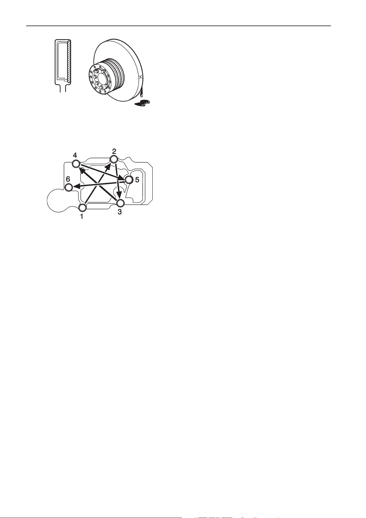
Vibration Damper Inspection
NOTE! When installing a damper protective
cover to the engine, do not use a cover
enclosing the damper.
Visually check for fluid leaks, flaws, distortion, or discoloration or flaking of painted surfaces. Also check
for swelling (by measuring with a scale), and fluid leaks past staked portions.
Re-tighten Bolts and Nuts
Re-tighten the bolts and nuts on the following components:
* Timing gear case
* Crankshaft pulley
* Mounting brackets
* Exhaust manifold
* Turbocharger
* Cylinder heads
Check the cylinder head bolts and re-tighten them in
number sequence (1-2-3-4-5-6) if necessary. The
tightening torques of the bolts and nuts can be found
in technical data section of this manual.
42
Page 43
Maintenance: Engine
Plus d'informations sur : www.dbmoteurs.fr
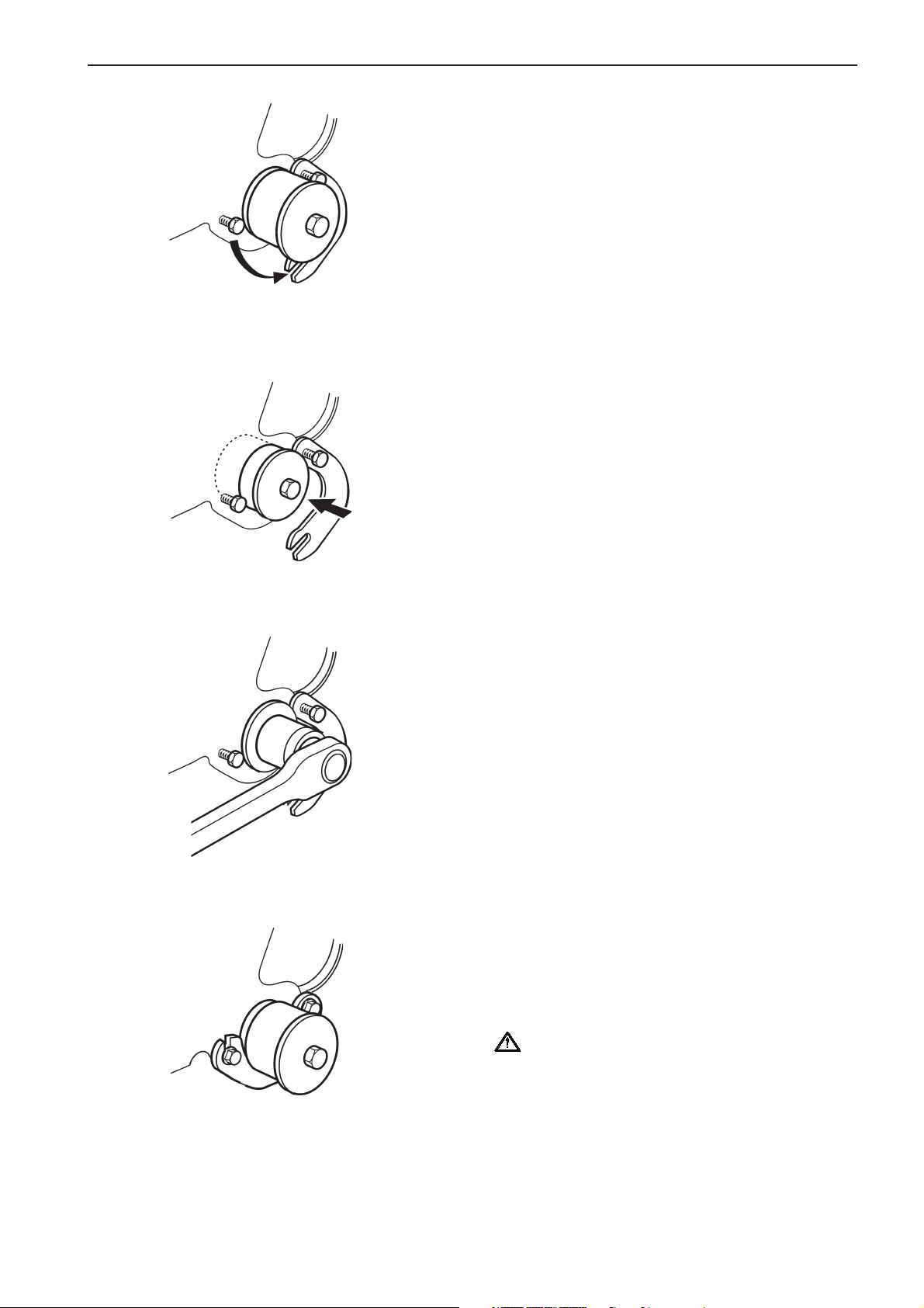
How to use the Turning Gear
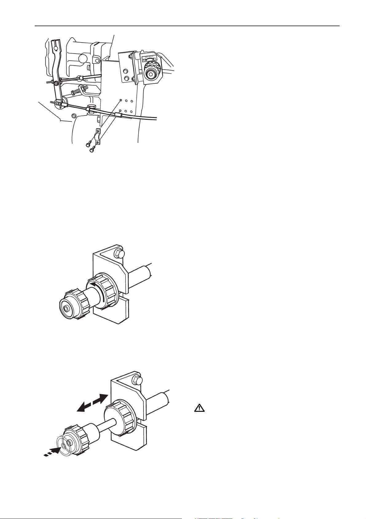
1. Loosen the two bolts securing the shaft lock plate
and remove the plate from the shaft (groove).
2. Push in the shaft all the way to the TURN posi-
tion.
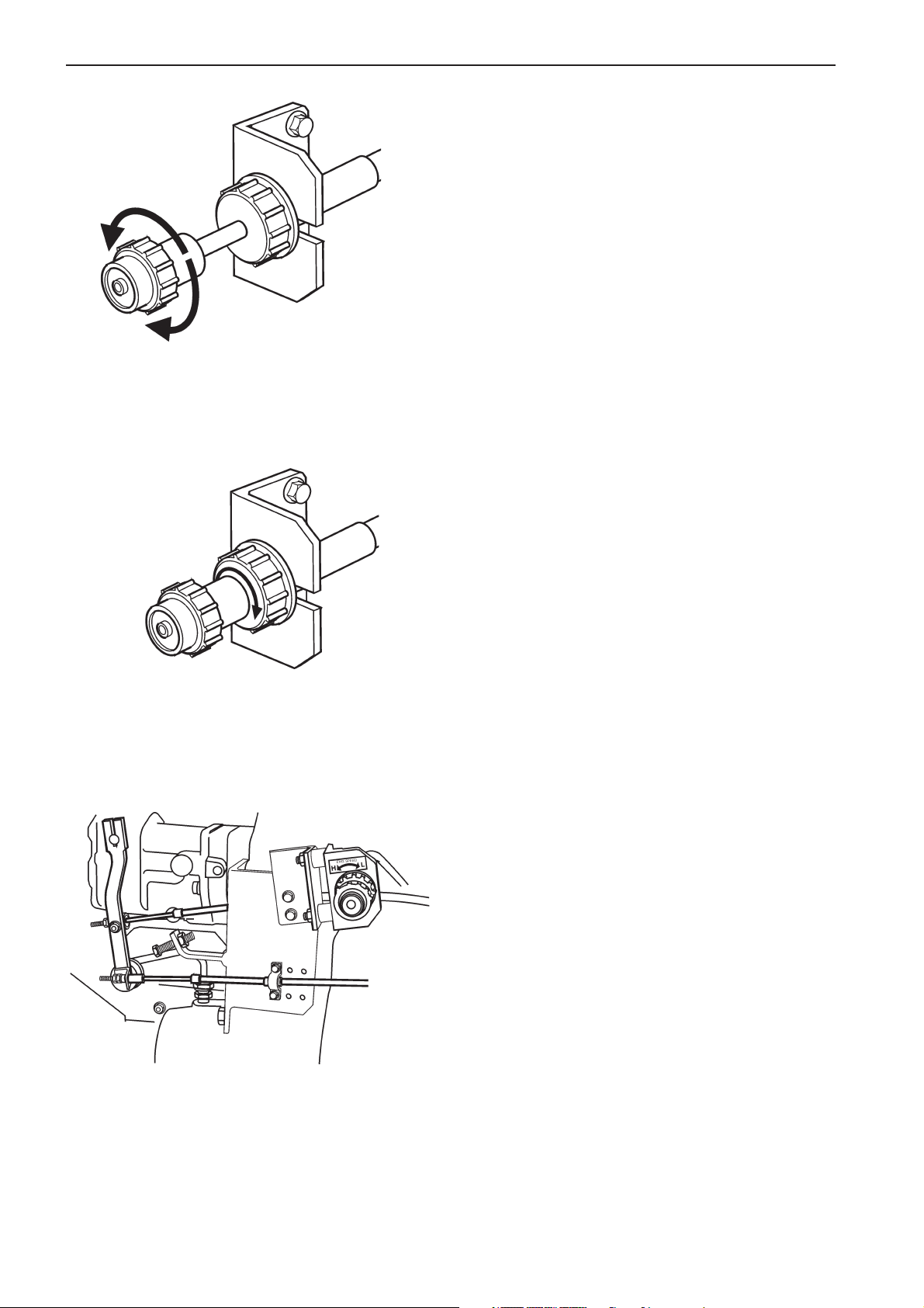
3. Put a socket to the hexagonal end of the shaft
and turn the shaft with a ratchet handle for turning.
4. After turning the engine, pull the shaft back to the
RUN position, secure the shaft with the locking
device and tighten the plate bolts. Make sure the
plate is secured properly.
WARNING! Before starting the engine, make
sure the turning gear is in the RUN position and
is locked.
43
Page 44

Maintenance: Fuel System
Plus d'informations sur : www.dbmoteurs.fr
Fuel system
Fuel system bleeding
Prime the fuel filters and fuel injection pump in the following sequence:
Bleeding the fuel filter
1. Put the fuel filter switching cock in the left filter
bleed position and loosen the left air vent plug.
2. Turn the priming pump plunger counterclockwise
to unlock the mechanism.
3. Move the plunger up and down until the fuel flows
free of bubbles from air and tighten the air vent
plug.
4. Put the fuel filter switching cock in the neutral position and repeat the above-described procedure
for the other fuel filter.
44
Page 45

Maintenance: Fuel System
Plus d'informations sur : www.dbmoteurs.fr
Bleeding the fuel injection pump
1. Loosen the air vent cock on the fuel injection
pump about 1.5 turns.
2. Move the priming pump cap up and down to start
the flow of fuel through the system.
3. When the fuel coming out of the air vent cock
shows no visible bubbles, lock the priming pump
cap while holding it down. Then tighten the air
vent cock.
Be sure to lock the priming pump cap before tightening the air vent plugs and cock. If this is not
done the cap does not return to the original position due to the pressure in the priming pump.
4. Tighten the priming pump cap by hand until the
tightening force increases, normally this occurs
after turning it approximately 70 to 90 degrees.
Mark this position on the priming pump cap to
make item 5 work more easily.
5. Tighten the priming pump cap an additional 120
to150 degrees using a wrench.
6. Clean the engine from spoiled fuel to prevent fire
and pollution of the environment.
IMPORTANT! If the priming pump cap is tighte-
ned too much (more than 240 degrees in total),
the top of the priming pump can be damaged.
IMPORTANT! Looseness of the priming pump
cap in combination with engine vibration may
cause engine failure and damage to the installation.
45
Page 46
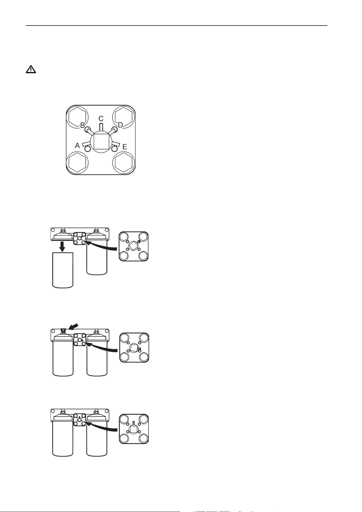
Maintenance: Fuel System
Plus d'informations sur : www.dbmoteurs.fr
Fuel filter change
Switchable fuel filters can be changed while the engine is running as the flow of fuel can be cut off to one filter at a
time.
WARNING! Working on or approaching a running engine is a safety hazard. Beware of rotating parts and hot
surfaces.
A. Right Filter bleed position
B. Right Filter change position
C. Neutral position
D. Left Filter change position
E. Left Filter bleed position
1. Place a drip pan under the fuel filter.
2. Put the fuel filter switching cock in the Left filter
change position and unscrew the left-hand fuel filter. Use a filter wrench if necessary.
3. Coat the gasket of a new filter with clean diesel
fuel.
4. Install the new filter in the filter bracket by hand.
When the gasket contacts the base, tighten 1/2 to
3/4 of a turn more.
5. Put the fuel filter switching cock in the Left filter
bleed position and loosen the left air vent plug until the fuel running out is free from air. Close the
air vent.
6. Put the fuel filter switching cock in the neutral position and repeat the above described procedure
for the other fuel filter.
46
Page 47
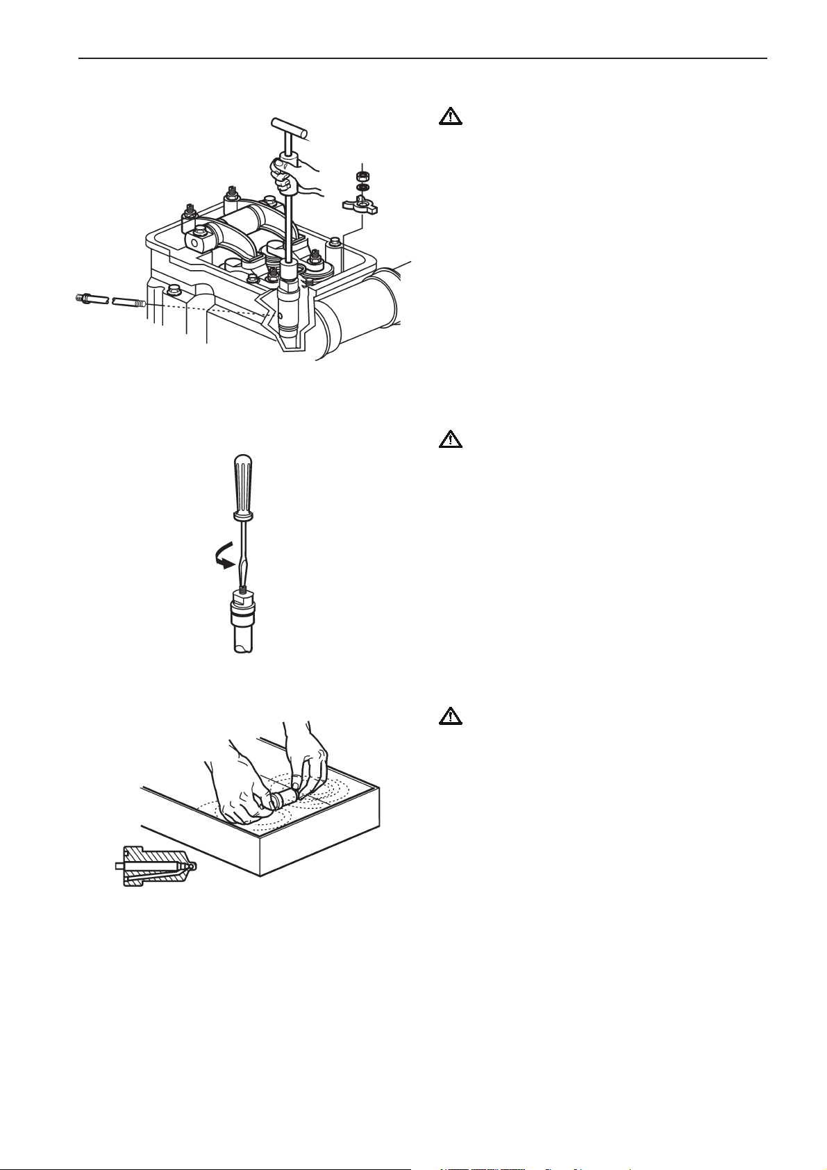
Maintenance: Fuel System
Plus d'informations sur : www.dbmoteurs.fr
Fuel injector nozzle change
IMPORTANT! Cover all open fuel injection pipes,
fuel intake openings and the fuel injectior nozzle
to keep dirt out
Remove the fuel injector
1. Remove the rocker cover.
2. Remove the clamp from the fuel injection pipe.
3. Remove the fuel injection pipe from the fuel injec-
tor.
4. Remove the injector inlet connector.
5. Remove the injector gland nut to take off the
gland.
6. Pull out the fuel injector using the special tool.
Remove the nozzle
IMPORTANT! The injector nozzle is very
delicate, handle with care.
1. Fasten the fuel injector in a vice with protection
plates.
2. Remove the set screw and the cap nut.
3. Loosen the adjusting screw with a screw driver
until it can be loosened by hand.
Note! This operation is required to release spring
pressure applied to the nozzle tip. When spring pressure is applied, it is hard to loosen the retaining nut.
3. Remove the retaining nut and remove the nozzle.
Nozzle cleaning
IMPORTANT! Do not change the pairing of
needle valve and body when cleaning more than
one at a time.
1. Dip the nozzle in clean fuel oil, and disassemble
the needle valve.
2. Clean the injection holes.
3. After cleaning, carefully insert the needle valve
into the body in clean oil.
47
Page 48

Maintenance: Fuel System
Plus d'informations sur : www.dbmoteurs.fr
Install the nozzle
1. Install the nozzle according to the pin on the
nozzle.
2. Tighten the retaining nut by applying the specified
torque 177 to 196 Nm (18 to 20kpm) [130 to 145
lbf.ft]. (Apply oil to the nut.)
IMPORTANT! Do not use Moly Disulfide.
3. Adjust the nozzle opening pressure and check
spray conditions.
Fuel injection pressure
WARNING! Do not allow the fuel injected from a
nozzle to contact the skin or body when
inspecting the nozzle using a nozzle tester. The
fuel injected from the nozzle has an extremely
high pressure, strong enough to penetrate skin
and causing serious injury.
1. Attach the fuel injector to the nozzle tester.
2. While watching the pressure gage of the nozzle
tester, push the handle down slowly.
IMPORTANT! If fuel drips from the end of
the nozzle tip it must be replaced.
3. When the handle is being pressed down, the fuel
is injected, and the pressure on the pressure
gage drops suddenly. The pressure value indicated at this point is the fuel injection start pressure.
4. Close the valve on the injection pump. If the pressure on the gage drops too fast ( most probably
due to lekage) the nozzle must be replaced.
NOTE! Make sure it isn’t the injection pump itself that
is leaking.
Nozzle opening pressure
34.32 MPa (350 kp/cm2) [4979 psi]
48
Page 49

Maintenance: Fuel System
Plus d'informations sur : www.dbmoteurs.fr
Fuel injection nozzle spray pattern
Check spray conditions when checking fuel injection
pressure. Good spray conditions are as follows:
· Fuel is injected from all nozzle holes.
· The fuel is sprayed in a conical shape.
· No big particles but fine ones.
· No oil drip is left after injection.
If the nozzle fails to spray fuel properly, replace with a
new one.
NOTE! Fuel injection pressure and nozzle spray pattern check intervals may be extended in steps of 250
hours if they are ok at 1000 hrs.
Adjust the fuel injection pressure
1. To adjust injection pressure, remove the set
screw from the nozzle holder, loosen the cap nut,
and then turn the adjusting screw. To increase
the injection pressure, tighten the screw. To decrease the injection pressure, loosen the screw.
2. When the pressure meets the standard value,
tighten the cap nut to 69 - 78 Nm (7 - 8 kpm)
[51 - 58 lbf.ft].
3. Tighten the set screw to 34 - 44 Nm
(3.5 - 4.5 kpm) [25 - 33 lbf.ft].
Fuel injector nozzle installation
1 . Remove the nozzle inlet connector from the fuel
injection nozzle.
2. Attach three 0-rings to the nozzle and grease
them.
3. Apply a small amount of grease to a gasket and
attach to the nozzle.
4. Insert the nozzle into the cylinder head aligning its
inlet connector hole to the connector hole in the
head.
5. Attach the nozzle inlet connector to the nozzle by
applying the specified torque, 64 to 74 Nm (6,5
to 7,5 kpm) [47 to 54 lbf].
6. Attach the nozzle gland and tighten the nut at the
specified torque (98 N -m (10 kgf m) [72 lbf]).
7. Attach the injection pipe and fuel leak-off pipe.
8. Before mounting the rocker cover, operate the
engine at approx. 850 rpm and check for any fuel
leakage from each joint. Install the rocker cover
after confirming no fuel leakage.
49
Page 50

Maintenance: Fuel System
Plus d'informations sur : www.dbmoteurs.fr
Injection timing inspection
The injection timing is indicated on the caution plate
attached to the No. 1 rocker cover. Check it before
inspection. Bring the piston for No. 1 cylinder to top
dead center on compression stroke as follows:
1. Turn the engine in the normal direction to align
the timing mark [1 .6] on the damper with the
pointer as shown.
2. Remove the No. 1 rocker cover and make sure
the inlet and exhaust valves for No. 1 cylinder
have some clearance. If these valves have no
clearance, turn the engine once again to align the
timing mark [1 .6].
NOTE! Do not confuse the No. 1 cylinder with No. 6.
When the piston for the No. 1 cylinder is in the abovementioned position, its inlet and exhaust valve are seated, presenting some clearance.
3. Turn back the engine approximately 60 degrees,
and turn it in the normal direction slowly until the
specified timing (indicated on the caution plate)
aligns with the pointer. To ensure proper injection
timing, make sure that the timing mark on the
coupling flywheel aligns with the pointer on the
fuel injection pump.
a. pointer
b. timing mark
Adjust fuel injection timing
1. Make sure the timing mark (indicated on the caution plate) is aligned with the pointer, with the piston for the cylinder at top dead center on compression stroke.
2. Loosen two bolts for the fuel injection pump coupling.
3. Turn the coupling flywheel until the timing mark
on the coupling flywheel aligns with the pointer on
the fuel injection pump.
4. Tighten the one nut for fuel injection pump coupling. Turn the engine to tighten the other side nut.
5. Turn the engine (two turns) to recheck the injection timing for verification.
50
Page 51

Maintenance: Fuel System
Plus d'informations sur : www.dbmoteurs.fr
Fuel control
Fuel control link joints inspection
Check the ball joints for play. If there is more than
0.1 mm [0.004in.] play, replace the ball joints with
new ones.
WARNING! In case of a control link having ball
joints that is an integral part of the link, change
the link as an assembly.
Injection pump control rack operation
Move the stop lever back and forth a few times and
find out if the control rack can be operated smoothly.
WARNING! If the rack sticks this must be fixed
before starting the engine.
WARNING! Never try to control the engine rpm
by moving the manual stop control leaver in the
opposite direction of the arrow. This casn result
in serius harm of the installation.
51
Page 52

Maintenance: Fuel System
Plus d'informations sur : www.dbmoteurs.fr
Twin fuel pre-filter/water separator
WARNING! Working on or approaching a
running engine is a safety hazard. Beware of
rotating parts and hot surfaces.
The dual filter is equipped with a pressure gauge (1)
indicating when it is time to change the filter insert.
The filter inserts must be changed according to the
maintenance schedule recommendations or earlier if
the pressure gauge indicates a vacuum of 6–10 inHg
at idling speed or 16–20 inHg at full engine speed/
load.
Drainage
Place a receptacle under the filter. Drain off water
and contaminants through the plug (1) in the bottom
of the bowl.
IMPORTANT! Do not drain until a few hours after
stopping.
Change the filter elements
The dual filter inserts can be changed while the engine is running as the flow of fuel can be cut off to one
filter container at a time.
The flow of the fuel is governed by putting the knob
(1) in the following positions:
A: Normal running (both filters connected).
B: Left filter insert can be changed.
C: Right filter insert can be changed.
D: Both filters turned off.
52
Page 53

Maintenance: Fuel System
Plus d'informations sur : www.dbmoteurs.fr
Close the fuel cocks on the tank or cut off the flow of
fuel with the knob (1) for the filter insert to change if
running.
WARNING! Working on or approaching a
running engine is a safety hazard. Beware of
rotating parts and hot surfaces.
1. Place a receptacle under the filter.
2. Undo the T-bolt (2) and remove the cover (3).
3. Take out the insert carefully while turning it.
4. Drain off water and contaminants through the
drain plug (4).
5. Fit a new filter insert and fill the container with cle-
an fuel.
IMPORTANT! Cleanliness! No contaminants
must be allowed in the fuel system.
6. Change the gasket on the cover and the O-ring
on the T-bolt. Moisten the gasket and O-ring with
fuel before assembling.
7. Fit the cover and tighten it by hand.
8. Wipe off any fuel from the heat shield.
9. Dual filter: Change the other filter insert in the
same way.
10. Open the fuel cocks and put the knob (1) in position for normal running. Make sure there are no
leaks.
53
Page 54

Maintenance: Lubrication system
Plus d'informations sur : www.dbmoteurs.fr
Lubrication system
Lubrication oil level check
The oil level must be within the marked range on the
dipstick and must be checked daily.
IMPORTANT! The level must never be allowed
to drop beneath the minimum or rise above the
maximum mark on the dipstick.
Lubrication oil filling
Fill the engine with lubrication oil through the filler
pipe. For oil specification refer to chapter technical
data. The oil level should be within the marked area
on the dipstick. After filling oil, secure filler cap.
WARNING! Lubrication oil on hot surfaces or
electrical components may cause fire. Do not
smoke while filling oil or when handling oil containers.
IMPORTANT! Stop the engine when filling oil.
IMPORTANT! Avoid mixing oils of different
brands, additives used in the oils can cause
chemical reactions that may degrade the oil
performance.
IMPORTANT! The lubrication oil level must
never be allowed to drop beneath the lower, or
rise above the maximum, mark on the dipstick.
54
Page 55

Maintenance: Lubrication system
Plus d'informations sur : www.dbmoteurs.fr
Filling oil in new or reconditioned engine
If your engine is new or reconditioned you should
besides the actual filling of new lubrication oil also do
the following:
1. Remove the rocker cover. Lubricate the valve
mechanism and fill the camshaft oil bath from the
cylinder head. Repeat the procedure for each cylinder.
2. Mount all the rocker covers. Refer to section
Tightening torques for proper torques.
NOTE! Avoid running or cranking the engine without
the rocker covers mounted.
3. Remove the lubrication oil pipe connected to the
turbo.
Fill the turbo through the opening with 2 or 3
pumps of oil from the oil fill can. This has to be
done to secure lubrication of the turbo during the
first start-up.
IMPORTANT! Do not bend the pipe. This can
block the oil supply to the turbo.
4. Reconnect the lubrication oil pipe to the turbo properly.
5. Crank the engine 3 times for maximum 10 seconds with the emergency stop lever in the stop
position and check if the oil pressure rises properly.
6. Start the engine and operate it for about 10 minutes and check if the oil pressure rises properly.
Check the oil pan and related parts for oil leaks.
IMPORTANT! If oil pressure do not rise
immediately after start, stop the engine and
investigate. Do not restart until problem is fixed.
7. Check the oil level in the oil pan and add oil if necessary.
55
Page 56

Maintenance: Lubrication system
Plus d'informations sur : www.dbmoteurs.fr
Lubrication oil change
Always observe the recommended oil change interval.
IMPORTANT! Only use recommended grades of
oil (see chapter technical data).
1. Warm up the engine (this makes it easier to suck
the oil up from the sump). Then stop the engine.
WARNING! Hot oil and hot surfaces may cause
burns.
2. Connect a hose to the outlet pipe of the lubrication oil scavenging pump. Pump the oil out.
NOTE! Collect the old oil and filters and deposit in accordance with local regulations. Never dispose of old
oil or oil filters overboard.
3. Change the oil filters and the by-pass filter at every oil change (please refer to section oil filters
change).
4. Fill with oil to the correct level trough the oil filling
pipe.
5. Start the engine and allow it to idle. Check the oil
pressure and make sure that there are no leaks
by the filters.
WARNING! Approaching or working with a
running engine is a safety risk. Be careful to
avoid rotating components and hot surfaces.
6. Stop the engine. Wait a few minutes before you
check the oil level. Top up if necessary.
56
Page 57

Maintenance: Lubrication system
Plus d'informations sur : www.dbmoteurs.fr
Oil filter change
The oil filters can be changed while the engine is running as the oil flow can be directed through one filter
at a time.
1. Remove the cover from the filter switch valve by
disconnecting the two bolts.
WARNING! Working on or approaching a
running engine is a safety hazard. Beware of
rotating parts and hot surfaces.
2. Cut off the oil flow through the right filter by tur-
ning the setting valve in position C.
3. Unscrew the oil filter using the special tool. Dis-
card the filter.
NOTE! Place a container beneath the filter when
removing to avoid oil spill.
4. Lightly oil the new filter’s rubber gasket and check
its mating surface on the mounting.
5. Mount the new filter by hand until the gasket is in
contact with the sealing surface. Then tighten the
filter a further approximately 3/4 of a turn using a
filter wrench.
6. Put the filter on-line by turning the valve in posi-
tion A.
7. Replace the left filter as above. Position B is the
left filter change position.
8. Replace both full-flow filters and the by-pass filter
at the same change interval. Refere to next page
for by-pass oil filter change procedure.
NOTE! After a lubrication oil filter change, open the
filter and check for metal parts.
57
Page 58
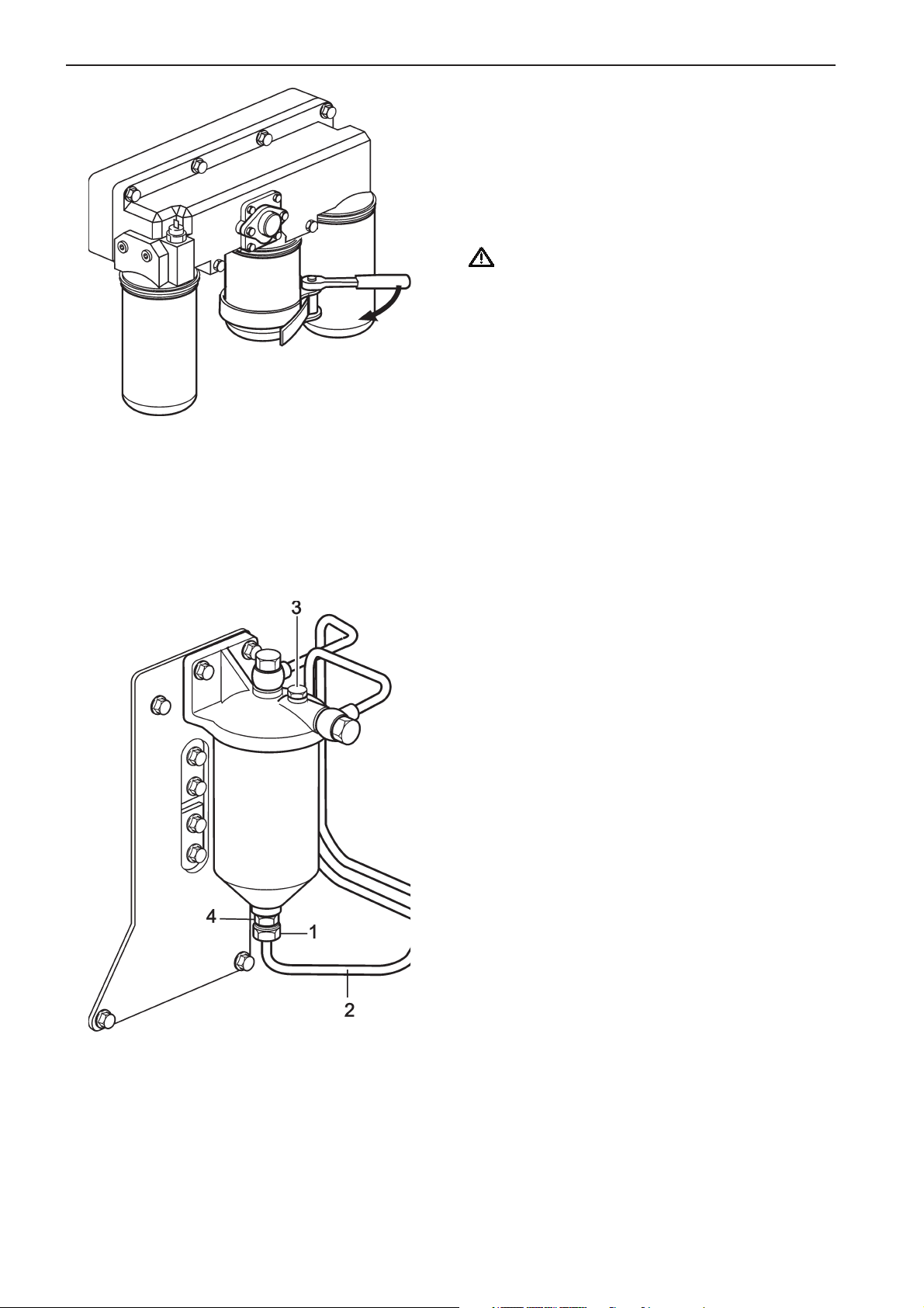
Maintenance: Lubrication system
Plus d'informations sur : www.dbmoteurs.fr
Lubrication oil by-pass filter
change
1. Stop the engine
2. Unscrew the oil filter using a special filter wrench.
Note! Place a container beneath the filter when removing to avoid oil spill.
Warning! Hot oil can cause burns.
3. Lightly oil the new filter’s rubber gasket and check
its mating surface on the mounting.
4. Screw on the new filter by hand until the gasket is
in contact with the sealing surface. Then tighten
the filter a further approximately 3/4 of a turn
using a filter wrench.
Hydraulic governor oil filter change
1. Place a drip pan under the governor oil filter.
2. Loosen the screw holding the pipe connecting the
oil filter and the governor (1).
3. Remove the pipe (2).
4. Open the air vent plug (3) so that the rest of the
remaining oil flows into the oil drip pan.
5. Remove the center bolt (4), remove the old filter
and mount a new.
6. Remove the air vent plug and fill the filter housing
with new oil.
7. Tighten the air vent plug.
58
Page 59
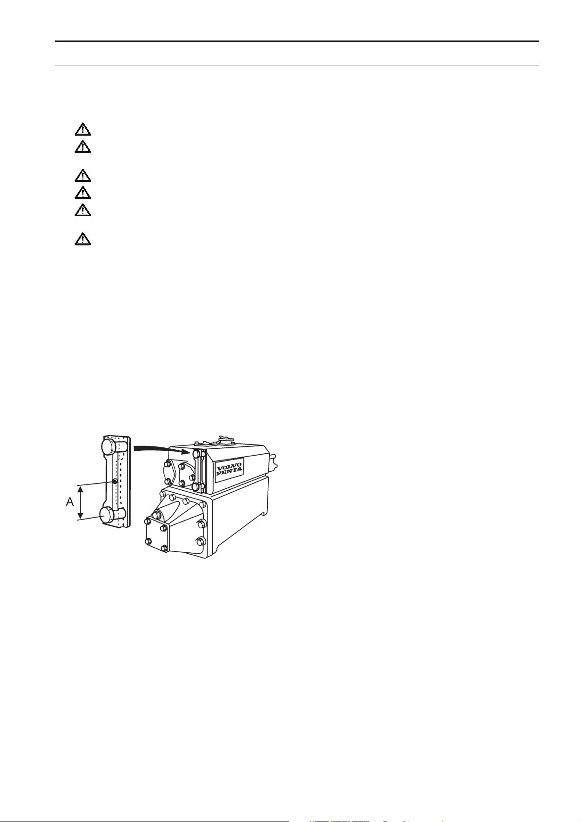
Maintenance: Freshwater system
Plus d'informations sur : www.dbmoteurs.fr
Freshwater system
The Freshwater system is the internal cooling system. It is a closed system and must be filled with a coolant that
protects the engine from internal corrosion and freezing. Anti-corrosive additives become less efficient with age
and the coolant must therefore be changed in accordance with the recommendations in the maintenance schedule.
WARNING! Never open the pressure cap when the engine is warm. Steam or hot fluid may spurt out.
WARNING! The coolant is dangerous to your health and an environmental hazard. Handle coolant with
care and dispose of old coolant in accordance with local regulations.
IMPORTANT! For coolant specification, refer to chapter “technical data” in the back of this manual.
IMPORTANT! Check the coolant level on a cold stationary engine.
IMPORTANT! Coolant to be added should have the same concentration as the coolant in the engine.
Do not add plain water.
IMPORTANT! Certain parts of the system are made of light alloy. Chemical additives must therefore not
be used when cleaning.
Coolant level check
MS engines
Make sure the level ends between the MIN and MAX
marks. If there are no marks, the coolant level should
be approximately 5 cm below the top of the filler cap.
Fill if necessary with the same type and concentration
of coolant that is already in the system. For coolant
specification refer to chapter “technical data” in the
back of this manual.
NOTE! Coolant to be added should have the same
concentration as the coolant in the engine. Do not
add plain water.
MT engines
The minimum cooling water level on a cold engine is
65 mm [from the bottom of the sight glass and up
(A)].
The cooling water level of a cold engine must never
reach higher than 5 mm below the top of the sight
glass. For coolant specification refer to chapter “technical data”.
59
Page 60
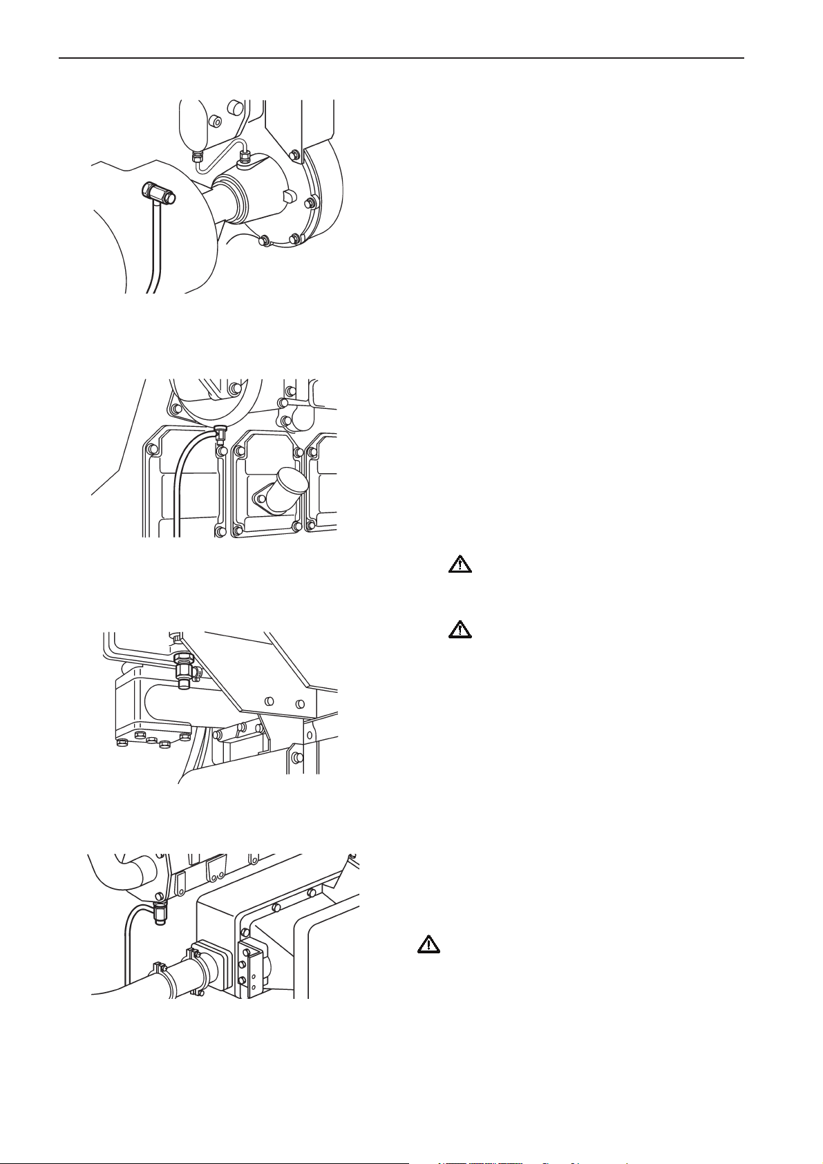
Maintenance: Freshwater system
Plus d'informations sur : www.dbmoteurs.fr
Coolant filling
Topping up
Fill the freshwater system with coolant to the correct
level through the filler opening in the expansion tank,
for correct level, refer to section “coolant level check”.
Fill slowly so that evacuated air is able to pass the filler opening.
Filling when the system is empty
1. Open the air ventilation cocks and close the coolant drain cocks.
2. Make sure that systems connected to the cooling
system also are ventilated, e.g. heater, water
heater.
3. Fill the freshwater system with coolant to the correct level through the filler opening in the expansion tank. For correct level, refer to section “coolant
level check”. Fill slowly letting air ibleed from the
ventilation cocks and the filler opening. When airfree coolant flows out, close the ventilation cocks.
4. To bleed the system, crank the engine 10 seconds while holding the emergency stop lever in
stop position. Repeat several times at one minute
intervals.
5. Check the coolant level and top up if needed.
IMPORTANT! Make sure that the engine is
filled with lubrication oil before starting or
cranking the engine.
IMPORTANT! The engine must not be
started before the system has been bled and
topped up.
6. Start the engine and run it under light load until
the thermostat valve opening temperature is
reached.
7. Check air vents for leaks.
8. Stop the engine and allow it to cool. Check the
coolant level in the expansion tank and top up if
needed.
Coolant drain
1. Remove the filler cap on the expansion tank.
2. Open the air vent cocks and then drain the coolant from the drain cocks.
IMPORTANT! Check that the coolant really
drains. Deposits may need to be removed inside
the drain plugs/taps.
3. Drain all other systems connected to the freshwater system, e.g. heater, water heater, etc.
4. Close all drainage points.
60
Page 61

Maintenance: Freshwater system
Plus d'informations sur : www.dbmoteurs.fr
Freshwater system flushing
The system should be flushed before changing coolant to avoid inferior cooling performance due to deposits in the cooling system.
1. Drain the coolant as described earlier.
2. Insert a hose into the filler opening in the heat ex-
changer and flush with fresh water.
3. Flush until the water running out of the drainage
points is clean.
4. Close all drainage points when the flushing water
has run out.
5. Fill with coolant. See section coolant filling when
empty.
61
Page 62
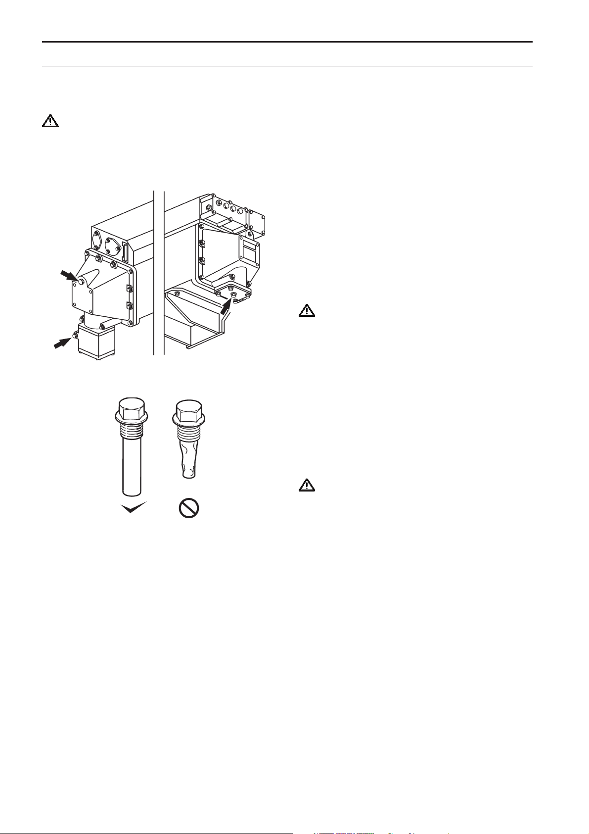
Maintenance: Seawater system
Plus d'informations sur : www.dbmoteurs.fr
Seawater system
The seawater system is the engine’s external cooling system. It cools the internal cooling system in an engine
mounted or externally mounted heat exchanger. The system is protected against galvanic corrosion by zinc anodes located in the heat exchanger.
WARNING! The seawater cocks and/or the cocks of the external cooling system must be closed before
commencing work on the seawater system. This due to the risk of sea water or water from the central
cooling system entering the vessel.
Draining the seawater system
Keep the engine room heated or use an antifreeze
coolant in the seawater system. Otherwise the seawater system must be drained when there is a risk of
freezing in cold weather.
1. Close the seawater in- and outlet cocks.
2. Drain the coolant from the external cooling system.
IMPORTANT! Check that the coolant really
drains. Deposits may need to be removed from
inside the drain plugs/taps.
Check and Change the zinc anodes
1. Drain the external cooling water as described in
the chapter draining the seawater system.
2. Unscrew the zinc anodes from the heat exchanger.
3. Change the anode if less than 50% remains. If
not, clean the anode with emery cloth to remove
the layer of oxide.
IMPORTANT! Do not use a wire brush or other
metal tool for cleaning as this may decrease the
galvanic protection.
4. Fit the zinc anodes. Make sure there is good contact between the anode and the metal goods.
5. Open the seawater cocks before starting the engine
6. Check the installation and make sure there are no
leaks.
Seawater filter check/change
If the vessel is equipped with a seawater filter refer to
the maintenance description supplied by the supplier
of the filter.
NOTE! If the water wherein the vessel operates is severely polluted, contains large amounts of seaweed,
etc., the filter must be checked more often than is
specified. The filter can otherwise become clogged
and the engine overheated.
62
Page 63
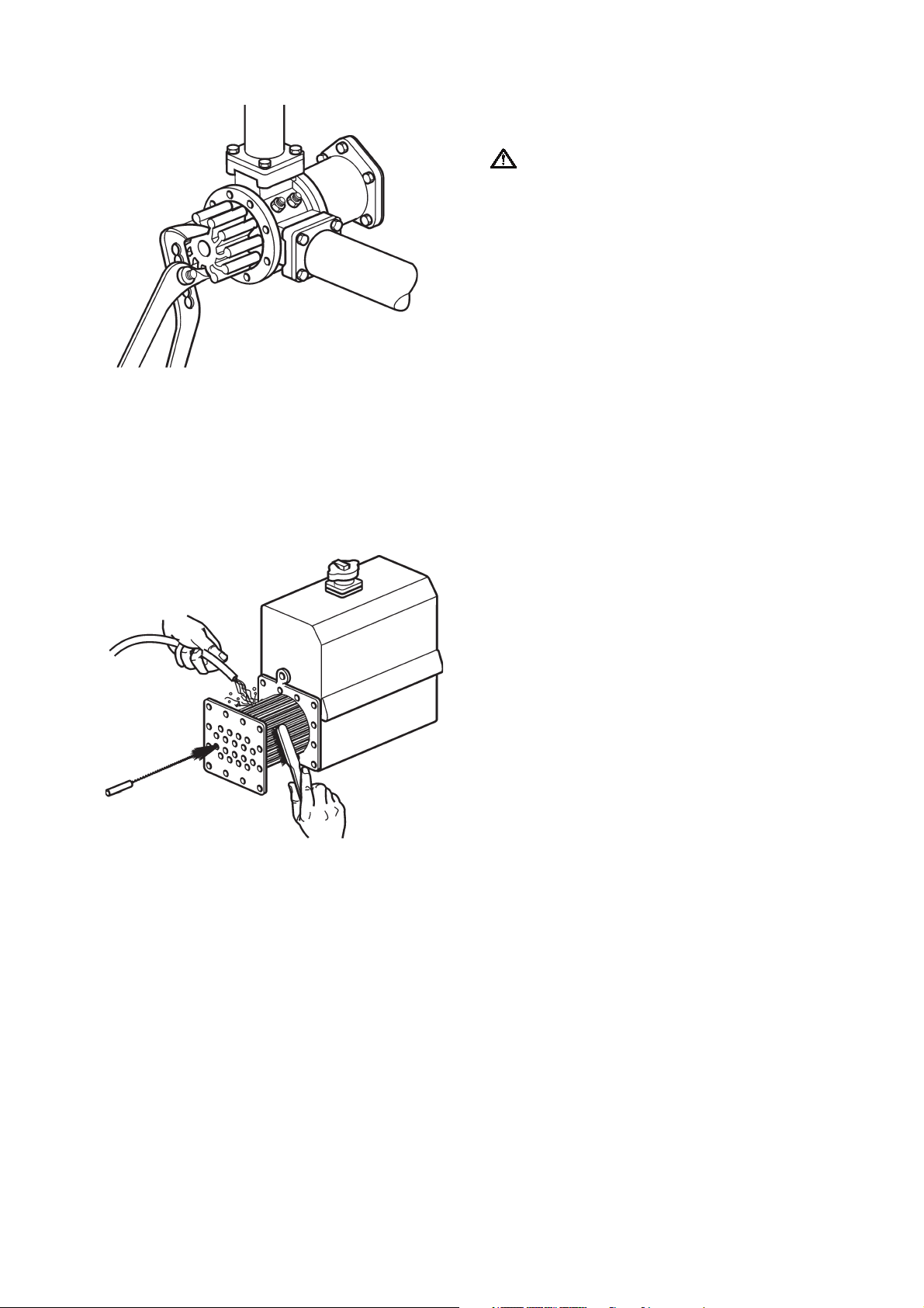
Seawater pump impeller check/
Plus d'informations sur : www.dbmoteurs.fr
hange
IMPORTANT! Always keep a spare impeller and
gasket in store.
1. Drain the external cooling water as described in
the chapter draining the seawater system.
2. Remove the pump end cover and the impeller.
3. Inspect the impeller. Change the impeller if there
are any visible cracks or other defects.
4. Clean the inside of the housing. Lubricate the
pump housing and the inside of the cover with
water-resistant grease (non-aggressive on rubber).
5. Push the impeller into position while rotating it in
the normal operating direction.
6. Fit the cover with a new gasket.
7. Open the seawater cocks.
Heat exchanger cleaning
Clean if there are signs of clogging, a gradual increase in engine temperature or high seawater pressure.
Check/clean the seawater filter first. Check also the
seawater pump impeller.
1. Drain the external cooling water as described in
the chapter draining the seawater system.
2. Detach the pipe connections from the heat ex-
changer.
3. Remove both covers from the heat exchanger
4. Clean the heat exchanger insert pipe using suita-
ble brushes while flushing through the pipe with
water
5. Refit the heat exchanger element and mound the
covers.
6. Connect the pipe connections to the heat exchan-
ger. Check gaskets and change if necessary.
7. Open the seawater cocks. Fill the freshwater sys-
tem.
8. Start the engine and make sure the seawater sys-
tem is not leaking.
63
Page 64

Maintenance: Air Inlet and Exhaust system
Plus d'informations sur : www.dbmoteurs.fr
Air Inlet and Exhaust Systems
Turbocharger Inspection
WARNING! Check the turbocharger only when
the engine is cool and the compressor wheel is
not running.
Check shaft play, take a hold of the compressor
wheel nut and turn the wheel to feel rattle and listen
for abnormal noise. Replace the bearings if the
wheel is noisy or rattles.
NOTE! Also check the turbocharger when the exhaust color is abnormal.
Cleaning the Air Cooler
Remove the air cooler, and blow compressed air in
the direction opposite to normal air flow.
Check air cooler drain pipe
Make sure the drain from the air cooler is not clogged.
64
Page 65

Maintenance: Air Inlet and Exhaust system
Plus d'informations sur : www.dbmoteurs.fr
Wash the air filter
Remove dust from air filter on the suction side of the
turbocharger silencer . Be sure to keep the air filter
clean to ensure optimum engine performance.
1. Remove the air filter from the silencer, and hand-
wash with a mild detergent.
2. Rinse the air filter with clean water.
3. After drying thoroughly, reinstall the air filter in the
silencer.
NOTE! If the air filter is damaged it must be replaced.
4. The standard interval for replacement of air filter
is every 2000 servicev hours or at least every 24
months.
65
Page 66

Maintenance: Electrical system
Plus d'informations sur : www.dbmoteurs.fr
Electrical system
Protective Devices Inspection
Make sure that the instruments and the alarm functions of the engine control system work properly.
Check the electrical wiring
Check for loose or damaged electrical cables. Damaged Gables must be replaced.
Starter motor inspection
1. Visually inspect the starter motor for damages
and dirt build-up. Repair and clean if needed.
2. Check the pinion for shifting and meshing action.
If the starter has a defect, consult your dealer.
3. Check if the clutch of the starter motor operates
smoothly.
Alternator Inspection
1. Inspect the alternator on functionality and clean it
if needed.
2. Remove the V-belt from the alternator. Turn the
alternator pulley by hand to check the rotation. If
the alternator has a defect, consult your dealer.
Drive belts. Check/Adjust/Change
WARNING! Stop the engine before
commencing maintenance work.
Check belt tension and condition regularly. If the belt
is too tight it can damage bearings and if it is too loose it may slip. Check and adjust after operation when
the belt is warm.
The belt is correctly tensioned when it can be depressed approximately 10 mm between the pulleys. Clean
the belt grooves before fitting a new belt.
IMPORTANT! Always change a belt that
appears worn or is cracked (belts working in
pairs must be replaced together).
IMPORTANT! Always keep the belts clear of
oil or grease. Oil or grease can cause the
belts to slip, which might shorten belt life.
66
Page 67

Inhibiting
Plus d'informations sur : www.dbmoteurs.fr
General
To prevent the engine and other equipment from being harmed during long (2 months or more) periods out of service, it must be conserved. It is of utmost importance that the conservation is performed correctly. Therefore we
have compiled a checklist of the most important points. Before taking the engine out of service for long periods, it
should be checked by a Volvo Penta dealer for possible needed overhaul or repaire of the engine and other equipment.
WARNING! Read the chapter “Maintenance” thoroughly before starting any maintenance work. It
contains directions for performing maintenance in a safe and correct manner. Certain preservatives are
flammable. Some are also dangerous to inhale. Provide good ventilation. Use a protective mask.
IMPORTANT! The following must be considered when cleaning with a high-pressure water jet: Never
point high-pressure water jets directly at seals, rubber hoses or electrical components. Never use the
high-pressure function when washing the engine.
Preparation
1. Drain the lubrication oil from the engine and fill it
with new lubrication oil or conserving oil.
IMPORTANT! Post a warning sign on the engine
that the conserving oil must be replaced with the
specified lubrication oil before starting the engine
again.
2. Run the engine on idling speed on a mixture of
70% fuel and 30% lubrication oil until the
complete fuel system is filled with the mixture,
then stop the engine (If possible, top up the fuel
tank to avoid condensation).
3. When the engine is coming to a stop but is still rotating, spray volatile rust preservative in the air intake and exhaust system. This to prevent rust on
the intake system.
4. Apply a coat of rust preservative to the exposed,
machined surfaces of the engine.
5. Cover breather, air inlet and exhaust openings
with tape.
6. Loosen the alternator and water pump drive belts.
7. Tape the starter and alternator terminals and
cover the starter and alternator with a
polyethylene sheet. Put a desiccant inside the
covering.
IMPORTANT! Never use vinyl sheets for
covering. This can result in condensation and
harm the installation
8. Remove the batteries and charge them. Clean the
terminal posts and coat them with acid free
Vaseline. Keep the batteries in a dry, cool place.
9. Cover the engine for weather protection.
Care during Storage
Recharge the battery at least once a month.
IMPORTANT! During longer periods out of opera-
tion, the preparations must be repeated every 12
months.
Return the Engine to Service
1. Remove the covering from the engine.
2. Connect well-charged batteries to the engine.
3. Remove the covering from the starter and
alternator.
4. Adjust the alternator and water pump drive belts.
5. Remove all coverings and tapings.
6. Drain the rust preservative from the engine and fill
the engine with recommended engine oil.
7. Fill the fuel tank and prime the fuel system.
8. Check under and around the engine for such items
as loose or missing bolts, oil, fuel or coolant leaks
and repair if needed.
9. Remove the rocker covers and lubricate the valve
mechanism.
10. Crank the engine three times, 10 seconds each
time, at intervals of one minute, with the fuel
supply shut off, to make sure the oil pressure
rises properly.
12. Start the engine.
13. Allow the engine to warm up at low idle.
14. When the engine has run long enough to warm up
apply the load and bring it to operating speed.
IMPORTANT! Store the engine in a well-
ventilated room.
IMPORTANT! It is not necessary to drain the
coolant because it contains coolant conditioner.
67
Page 68

Inhibiting
Plus d'informations sur : www.dbmoteurs.fr
Storage of Engine in Operating
Condition
Service the engine once a month in the following
manner:
1. Crank the engine two times, for 10 seconds each
time, with the starter at intervals of 30 seconds,
with the fuel supply shut off.
2. Start and run the engine under no-load condition
for 5 to l0 minutes.
IMPORTANT! If the engine is fitted with a wet
exhaust system and the exhaust is situated
below the water line the above has to be performed twice a week (if the exhaust is situated
above the water line, once a week is enough).
68
Page 69

Troubleshooting
Plus d'informations sur : www.dbmoteurs.fr
A number of symptoms and possible causes for engine disturbances are described in the table below. If faults or
hitches arise that you cannot solve alone, you must always get in touch with your Volvo Penta dealer.
NOTE! Dust and foreign particles are the most common cause of excessive wear of parts. When disassembling
a component, take measures to prevent dust and foreign particles from entering it.
WARNING! Read the safety directions for maintenance and service in the chapter “Safety information”
before starting any work.
IMPORTANT! Handle parts carefully. Only use original Volvo Penta spare parts.
Symptoms and possible causes
Starter motor does not rotate when cranking 1,2,3,4,5,6
Starter motor rotates slowly when cranking 1,2,3,22,48,49
Engine does not start ,8,9,10,11,12,13,14,15,20,21,23,24,28,50,58
Engine is difficult to start 8,9,10,11,12,13,14,15,20,21,23,24,28,50,51
Engine starts but stops again 8,9,10,11,12,13,14,15,20,21,23,24,28,50,51
52,53
Engine does not reach correct operating speed 8,9,10,11,12,13,14,15,18,19,20,21,22,
23,24,25,26,27,28,33,36,53,58
Engine runs unevenly 8,9,10,11,12,13,14,15,16,17,23,24,28,29
51,58
Engine knocks 21,29,52
Engine vibrates 9,17,23,33,34
Engine can not be stopped 2,3,4,6,54
High fuel consumption 13,15,17,19,20,21,25,26,28,30,33
Black or Dark gray exhaust smoke 13,15,17,18,19,20,21,28,30
Blue or white exhaust smoke 17,19,20,21,22,30,33,43,44,51,59
High lubrication oil consumption 22,32,33,34,44
Lubrication oil pressure too low 22,31,35,45,46
Coolant temperature too high 26,38,39,40,41,42,43,55
Coolant temperature too low 43
No charge or poor charge 2,3,47,56,57
1. Defective starter
2. Flat batteries
3. Poor contact/broken cables
4. Main switch turned off
5. Control lever not in neutral/control
position not activated
6. A fuse/circuit breaker has blown/tripped
7. Lack of fuel
8. Blocked fuel filter
9. Defective fuel filter
10. Blocked fuel pipes
11. Defective fuel pipes
12. Blocked fuel supply pump
13. Defective fuel supply pump
14. Blocked fuel injection pump
15. Defective fuel injection pump
16. Blocked fuel injection nozzles
17. Defective fuel injection nozzles
18. Incorrect valve clearance
19. Incorrect fuel injection timing
20. Low compression pressure
21. Improper fuel oil
22. Improper lubrication oil
23. Air in fuel system
24. Water/contamination in fuel
25. Boat abnormally loaded
26. Fouled hull/propeller
27. Engine speed control wrongly adjusted
28. Insufficient air supply
29. Too high coolant temperature
30. Too low coolant temperature
31. Too low lubrication oil level
32. Lubrication oil leakage
33. Worn cylinder liners and/or piston rings
34. Worn valve stem seals
35. Blocked lubrication oil filter
36. Defective/wrong propeller
37. Faulty engine mounting
38. Too low coolant level
39. Air in fresh water system
40. Blocked sea water inlet/pipe/filter
41. Circulation pump drive belt slips
42. Defective cooling water pump
43. Defective/wrong thermostat
44. Too high lubrication oil level
45. Defective lubrication oil pump
46. Defective relief valve
47. Alternator drive belt slips
48. Clutch is engaged
49. Defective bearings or abnormal cylinder
friction
50. Fuel supply pump strainer blocked
51. Very cold engine and lubrication oil
52. Heavy initial load
53. Propeller/propeller shaft blocked
54. Engine consume lubrication oil or combustible gas
55. Cylinder liner have scalings or such that
reduce cooling effect
56. Alternator/Rectifier broken
57. Faulty governor
58. Broken piston
69
Page 70

Technical Data
Plus d'informations sur : www.dbmoteurs.fr
D25A MS
General
Type designation D25A-MS
Number of cylinders .............................................. 6
Displacement ......................................................... 24,51 liters (1496 in
Nominal idling speed ............................................. not available
Low idling speed .................................................... 625 ±25 rpm
High idling speed ................................................... not available[rating 1] not available[rating 2]
Valve clearance* ................................................... 0,6 mm (0,024”) [inlet] 0,8 mm (0,031”) [outlet]
Compression pressure
at starter motor speed (120 rpm) .......................... not available
Dry weight engine, without oil and coolant
without reverse gear or clutch, approx. ................ 2320 kg (5116 lbs)
Exhaust temperatures: 440 kW Rating 1
1008 r/min. ............................................................. 300°C/(527°F)
1270r/min. .............................................................. 380°C/(716°F)
1454 r/min. ............................................................. 390°C/(734°F)
1600 r/min. ............................................................. 380°C/(716°F)
Exhaust temperatures: 485 kW Rating 2
3
)
1039 r/min. ............................................................. 348°C/(658°F)
1310r/min. .............................................................. 440°C/(824°F)
1500 r/min. ............................................................. 445°C/(833°F)
1650 r/min. ............................................................. 450°C/(842°F)
* Applies to cold engine.
Lubricating system
Oil capacity, approx. Including oil filters
No engine inclination ............................................. 160 liters (42,3 US gals)
volume difference min. –max. .............................. 30 liters (7,9 US gals)
Oil pressure, hot engine:
at operating speed ................................................. 0,50-0,64 MPa (71-93 psi)
at idling speed ....................................................... min.0,20-0,30 MPa (29-43 psi)
Cooling system
Freshwater system capacity
including heat exchanger, approx. ........................ 50 liters (13,2 US gals)
Electrical system
System voltage ..................................................... 24V
AC generator:
voltage/max. amperage ......................................... 24V/35A
output, approx. ...................................................... 840W
Battery electrolyte density at +25°C (77°F):
fully charged battery .............................................. 1,28 g/cm3 = 0,0462 lb/in3 (1,24 g/cm3 = 0,0448 lb/in3)*
3
battery recharged at .............................................. 1,24 g/cm
* Note. Applies to batteries with tropical acid.
70
= 0,0448 lb/in3 (1,20 g/cm3 = 0,0434 lb/in3)*
Page 71

Technical Data
Plus d'informations sur : www.dbmoteurs.fr
D25A MT
General
Type designation D25A-MT
Number of cylinders .............................................. 6
Displacement ......................................................... 24,51 liters (1496 in
Nominal idling speed ............................................. not available
Low idling speed .................................................... 625 ±25 rpm
High idling speed ................................................... not available[rating 1] not available[rating 2]
Valve clearance* ................................................... 0,6 mm (0,024”) [inlet] 0,8 mm (0,031”) [outlet]
Compression pressure
at starter motor speed (120 rpm) .......................... not available
Dry weight engine, without oil and coolant
without reverse gear or clutch, approx. ................ 2900 kg (6395 lbs)
Exhaust temperatures: 470 kW Rating 1
1008 r/min. ............................................................. 280°C/(536°F)
1270 r/min. ............................................................. 360°C/(680°F)
1474 r/min. ............................................................. 376°C/(709°F)
1600 r/min. ............................................................. 380°C/(716°F)
Exhaust temperatures: 520 kW Rating 2
3
)
1039 r/min. ............................................................. 327°C/(621°F)
1310 r/min. ............................................................. 395°C/(743°F)
1500 r/min. ............................................................. 406°C/(763°F)
1650 r/min. ............................................................. 400°C/(752°F)
* Applies to cold or warm engine (stopped).
Lubricating system
Oil capacity, approx. including oil filters
No engine inclination ............................................. 160 liters (42,3 US gals)
volume difference min. –max. .............................. 30 liters (7,9 US gals)
Oil pressure, hot engine:
at operating speed ................................................. 0,50-0,64 MPa (71-93 psi)
at idling speed ....................................................... min.0,20-0,30 MPa (29-43 psi)
Cooling system
Freshwater system capacity
including heat exchanger, approx. ........................ 115 liters (30,4 US gals)
Electrical system
System voltage ..................................................... 24V
AC generator:
voltage/max. amperage ......................................... 24V/35A
output, approx. ...................................................... 840W
Battery electrolyte density at +25°C (77°F):
fully charged battery .............................................. 1,28 g/cm3 = 0,0462 lb/in3 (1,24 g/cm3 = 0,0448 lb/in3)*
battery recharged at .............................................. 1,24 g/cm
* Note. Applies to batteries with tropical acid.
3
= 0,0448 lb/in3 (1,20 g/cm3 = 0,0434 lb/in3)*
71
Page 72

Technical Data
Plus d'informations sur : www.dbmoteurs.fr
D30A MS
General
Type designation D30A-MS
Number of cylinders .............................................. 6
Displacement ......................................................... 29,96 liters (1828 in
Nominal idling speed ............................................. not available
Low idling speed .................................................... 625 ±25 rpm
High idling speed ................................................... not available[rating 1] not available[rating 2]
Valve clearance* ................................................... 0,6 mm (0,024”) [inlet] 0,8 mm (0,031”) [outlet]
Compression pressure
at starter motor speed (120 rpm) .......................... not available
Dry weight engine, without oil and coolant
without reverse gear or clutch, approx. ................ 2420 kg (5336 lbs)
Exhaust temperatures: 445 kW Rating 1
850 r/min. .............................................................. 309°C/(588°F)
1072 r/min. ............................................................. 395°C/(743°F)
1227 r/min. ............................................................. 419°C/(786°F)
1350 r/min. ............................................................. 395°C/(734°F)
Exhaust temperatures: 490 kW Rating 2
3
)
882 r/min. .............................................................. 298°C/(568°F)
1111 r/min. ............................................................. 378°C/(712°F)
1272 r/min. ............................................................. 389°C/(732°F)
1400 r/min. ............................................................. 390°C/(734°F)
* Applies to cold or warm engine (stopped).
Lubricating system
Oil capacity, approx. including oil filters
No engine inclination ............................................. 160 liters (42,3 US gals)
volume difference min. –max. .............................. 30 liters (7,9 US gals)
Oil pressure, hot engine:
at operating speed ................................................. 0,50-0,64 MPa (71-93 psi)
at idling speed ....................................................... min.0,20-0,30 MPa (29-43 psi)
Cooling system
Freshwater system capacity
including heat exchanger, approx. ........................ 55 liters (14,5 US gals)
Electrical system
System voltage ..................................................... 24V
AC generator:
voltage/max. amperage ......................................... 24V/35A
output, approx. ...................................................... 840W
Battery electrolyte density at +25°C (77°F):
fully charged battery .............................................. 1,28 g/cm3 = 0,0462 lb/in3 (1,24 g/cm3 = 0,0448 lb/in3)*
3
battery recharged at .............................................. 1,24 g/cm
* Note. Applies to batteries with tropical acid.
72
= 0,0448 lb/in3 (1,20 g/cm3 = 0,0434 lb/in3)*
Page 73

Technical Data
Plus d'informations sur : www.dbmoteurs.fr
D30A MT
General
Type designation D30A-MT
Number of cylinders .............................................. 6
Displacement ......................................................... 29,96 liters (1828 in
Nominal idling speed ............................................. not available
Low idling speed .................................................... 625 ±25 rpm
High idling speed ................................................... not available[rating 1] not available[rating 2]
Valve clearance* ................................................... 0,6 mm (0,024”) [inlet] 0,8 mm (0,031”) [outlet]
Compression pressure
at starter motor speed (120 rpm) .......................... not available
Dry weight engine, without oil and coolant
without reverse gear or clutch, approx. ................ 3000 kg (6615 lbs)
Exhaust temperatures: 480 kW Rating 1
850 r/min. .............................................................. 280°C/(536°F)
1072 r/min. ............................................................. 355°C/(671°F)
1227 r/min. ............................................................. 375°C/(707°F)
1350 r/min. ............................................................. 385°C/(725°F)
Exhaust temperatures: 530 kW Rating 2
3
)
882 r/min. ............................................................ 290°C/(554°F)
1111 r/min. ............................................................. 372°C/(702°F)
1272 r/min. ............................................................. 404°C/(759°F)
1400 r/min. ............................................................. 412°C/(744°F)
* Applies to cold or warm engine (stopped).
Lubricating system
Oil capacity, approx. including oil filters
No engine inclination ............................................. 160 liters (42,3 US gals)
volume difference min. –max. .............................. 30 liters (7,9 US gals)
Oil pressure, hot engine:
at operating speed ................................................. 0,50-0,64 MPa (71-93 psi)
at idling speed ....................................................... min.0,20-0,30 MPa (29-43 psi)
Cooling system
Freshwater system capacity
including heat exchanger, approx. ........................ 120 liters (31,7 US gals)
Electrical system
System voltage ..................................................... 24V
AC generator:
voltage/max. amperage ......................................... 24V/35A
output, approx. ...................................................... 840W
Battery electrolyte density at +25°C (77°F):
fully charged battery .............................................. 1,28 g/cm3 = 0,0462 lb/in3 (1,24 g/cm3 = 0,0448 lb/in3)*
3
battery recharged at .............................................. 1,24 g/cm
* Note. Applies to batteries with tropical acid.
= 0,0448 lb/in3 (1,20 g/cm3 = 0,0434 lb/in3)*
73
Page 74

Standard Control System
Plus d'informations sur : www.dbmoteurs.fr
Fuel specification
Fuel must comply with national and international standards at the least, e.g.:
JIS KK 2204. ........................ Type1, Type2, Type3
ASTM, D975 ................................... No.1-D, No.2-D
BS2869 ................................... Class-A1, Class-A2
DIN51601 ............................................. Diesel-Fuel
ISO8217 ............................................... DMX-Class
Note! It is necessary to use a fuel that has a pour point suitable for ambient temperature during the operation of
the engine. Consult the supplier to select the right type.
Property Use limit
Flash point.............................................................. As stipulated by regulation
First distillation point .............................................. 170°C (338°F) or more
90% distillation point .............................................. 330 to 380°C (626 to 716°F)
Pour point ............................................................... 6°C (10.8°F) below ambient temperature
Cloud point ............................................................. Below ambient temperature
Carbon residue (10% residue oil) ........................... 0.4 weight % or lower
Cetan number ........................................................ 45 or more
Cetan index (new) .................................................. 45 or more
Kinematic viscosity ................................................. 2.0 mm²/S or more [30°C (86°F)]
............................................................................... 8.0 mm²/S or lower [50°C (122°F)]
............................................................................... 10.5 mm²/S or lower [40°C (104°F)]
............................................................................... 16.0 mm²/S or lower [30°C (86°F)]
Sulfur content ......................................................... 0.2 weight % or lower
Water and sediment ............................................... 0.1 volume % or lower
Ash ......................................................................... 0.03 weight % or lower
Copper plate corrosion (100°C)[212°F], 3h ............ No. 3 or lower
Specific gravity (15°C/4°C [59°F/39°F] .................. 0.83 to 0.87
Coking test ............................................................. Not carbonized 100% at 250°C (482°F)
Aromatics content .................................................. 38 weight % or lower
Particulate contaminant .......................................... 5.0 mg/liter or lower
Asphaltene ............................................................. 0.1 weight % or lower
74
Page 75
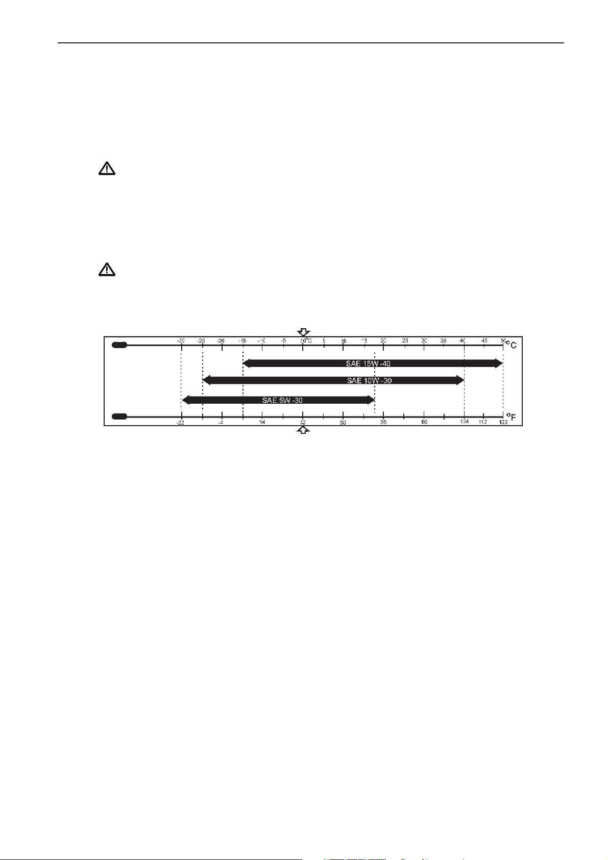
Technical Data
Plus d'informations sur : www.dbmoteurs.fr
Lubrication oil specification
Recommended types of engine oil
Use lubrication oil that meets Class CF standard (recommended engine oil). Class CE and CF-4 engine oils are
designed for diesel fuel with a sulfur content of less than 0,5% and less than 0,2%, respectively. Since the sulfur
content of most Class-A diesel fuel exceeds 0,5%, do not use class CE or CF-4 engine oil when using class-A
diesel fuel
Important! Use of improper or inferior oil can cause excessive wear of bearings and moving parts,
thus shortening the engine life. It can also result in sticking of piston rings and seizing of pistons in the
cylinders, thus causing major damage.
Selection of oil viscosity
Use the following chart to select appropriate oil viscosity according to the ambient temperature. Recommended
oil viscosity is SAE 15W-40 for all seasons.
Important! Excessively high oil viscosity causes power loss and higher oil temperature, while
excessively low oil viscosity results in inadequate lubrication and leakage of combustion gas with
increased wear and reduced output as a result.
75
Page 76

Technical Data
Plus d'informations sur : www.dbmoteurs.fr
Coolant specification
Always use Volvo Penta Coolant in the freshwater cooling circuit. Volvo Penta Coolant acts both as anti-freeze
agent and provides corrosion protection for the metal parts of the cooling system. Future claims might be rejected should Coolant 90 not have been used.
Important! Mixing other types of concentrated coolant with Volvo Penta Coolant, may decrease
corrosion protection and may damage the engine or block the cooling system.
Water
Always use clean water that complies with the requirements in ASTM D4985 X1.1. If these requirements are not
complied with, corrosion may occur, which would result in impaired cooling performance.
Total fixed particle content ..................................... < 340 ppm
Total hardness ....................................................... < 9,5 °dH
Chloride .................................................................. < 40 ppm
Sulphate ................................................................. < 100 ppm
pH value ................................................................. < 5,5 – 9
Silica....................................................................... < 20 mg Si02/l
Iron ......................................................................... < 0.10 ppm
Manganese ............................................................ < 0.05 ppm
Conductivity ............................................................ < 500 ìS/cm
Organic content, CODMn ....................................... <15 mg kMnO4/L
Mixing ratio
The mixture of Volvo Penta Coolant and water should contain 40-55% Volvo Penta Coolant. If the coolant contains less than 40% Volvo Penta Coolant, the cooling galleries in the engine or radiator may be blocked by contamination. If the coolant contains more than 60% Volvo Penta Coolant the cooling ability of the coolant mixture
is impaired, this may cause the engine to overheat. Too high concentration of Volvo Penta Coolant also impairs
the frost protection.
Important! The mixture of Volvo Penta Coolant and water may never contain less than 40% Volvo
Penta Coolant.
76
Page 77

Tightening Torque Tables
Plus d'informations sur : www.dbmoteurs.fr
Important Bolts and Nuts D25
Thread Torque
Description Diam.xPitch Nm kpm lbf.ft Notes
(M-Thread)
Cylinder Head 22 x 2,5 539 55 398 (a) (b) (c)
Cylinder head nozzle gland (studs) 14 x 2,0 69-78 7-8 51-58
Rocker case 12 x 1,25 108 11 80
Rocker shaft 14 x 2,0 147 15 108
Rocker arm lock nuts 12 x 1,25 64 6,5 47
Bridge lock nuts 10 x 1,25 55 5,6 40
Camshaft gear 12 x 1,25 127 13 94
Camshaft thrust plate 12 x 1,25 59 6 43
Main bearing caps 22 x 2,5 490 50 362 (a)
Hanger 12 x 1,25 108 11 80
Piston cooling nozzle 12 x 1,75 34 3,5 25 (d)
Timing gear case 16 x 1,5 216 22 159
Rear plate 12 x 1,25 108 11 80
Oil pan 12 x 1,25 59 6 43
Front mounting bracket 12 x 1,25 108 11 80
Rear mounting bracket 16 x 1,5 216 22 159
Connecting rod bearing caps 22 x 1,5 539 55 398 (a) (e)
Flywheel 22 x 1,5 539 55 398 (a)
Viscous damper 22 x 1,5 490 50 362
Rear idler shaft 12 x 1,25 108 11 80
Rear idler shaft thrust plate 10 x 1,25 29 3 22
Exhaust manifold V-clamp nuts 8 x 1,25 19,6 2 14,5
Exhaust manifold mounting bolts 1/4 x 28 9 0,9 6,5 UNF
Exhaust pipe V-clamps 10 x 1,5 98 10 72
Oil pump 12 x 1,25 108 11 80
Oil pump cover 10 x 1,25 26,3-39,7 2,7-4,1 18-32
Fresh water pump 12 x 1,25 59 6 43
Fresh water pump shaft pulley (nuts) 24 x 1,5 245 25 181 For alternator drive.
(a) Wet , apply lubrication oil to the threads of the nut and bolt.
(b) 2-step tightening method,
(c) Tighten cylinder head bolts according to the angle method, tighten to 294 Nm [30 kpm; 217 lbf.ft], then tighten 60° more.
(d) Extremely important to use torque wrench in tightening the piston cooling nozzles. Failure to do so may result in excessive
tightening torque, which may cause valve malfunctions that could lead to seizing of pistons due to insufficient lubrication.
(e) Tighten connecting rod caps according to the angle method, tighten to 245 Nm [25 kpm; 181 lbf.ft], then tighten 60° more.
77
Page 78

Technical Data
Plus d'informations sur : www.dbmoteurs.fr
Sea water pump cam (screw) 10 x 1,25 15,7-21,6 1,6-2,2 11,6-15,9
Sea water pump casing 8 x 1,25 7,4-9,8 0,75-1,0 5,42-7,23
Sea water pump cover 8 x 1,25 7,4-9,8 0,75-1,0 5,42-7,23
Sea water pump drive gear (nut) 24 x 2,0 191-201 19,5-20,5 141-148
Injection pump 12 x 1,25 108 11 80
Injection pump bracket 12 x 1,25 108 11 80
Injection pump drive case 12 x 1,25 108 11 80
Injection pump gear (nuts) 30 x 1,5 392 40 289
Injection pump laminate plate 12 x 1,25 103-113 10,5-11,5 76-83
Injection pump flywheel (nuts) 24 x 1,5 392 40 289
Injection pump coupling shaft 14 x 1,5 167-177 17-18 123-130 Tighten the slit part.
Injection pump plunger assembly 12 x 1,25 78-83 8-8,5 58-61
Injection pump delivery valve holder 30 x 1,5 235-255 24-26 174-188
Injection nozzle gland (nut) 14 x 1,5 98 10 72
Injection nozzle chip (nut) 28 x 1,5 177-196 18-20 130-145
Nozzle holder cap nuts 14 x 1,5 69-78 7-8 51-58
Injection nozzle set screw 10 x 1,5 34-44 3,5-4,5 25-33
Injection nozzle inlet connector 16 x 1,5 64-74 6,5-7,5 47-54
Injection pipes 18 x 1,5 49-69 5-7 36-51
Fuel filter air vent plug – 7,8-9,8 0,8-1,0 5,8-7,2
Fuel rack control lever 8 x 1,25 25 2,5 18 (b)
Governor drivecase 12 x 1,25 108 11 80
Starter 12 x 1,25 59 6 43
Turbocharger compressor wheel (nut) 11 x 1,0 – – – FD13(f)(g)(h)
Turbocharger V-clamp – 7,8-9,8 0,8-1,0 5,8-7,2 FD13 (g)
Turbocharger compressor wheel (nut) 1/2 x 20 – – – FD15UNF(f)(i)
Turbocharger turbine housing 10 x 1,5 25-28 2,6-2,9 19-21 FD15 (g)
Turbocharger V-clamp – 9,8-10,8 1,0-1,1 7,2-8,0 FD15 (g)
(a) Wet , apply lubrication oil to the threads of the nut and bolt.
(b) 2-step tightening method,
(c) Tighten cylinder head bolts according to the angle method, tighten to 294 Nm [30 kpm; 217 lbf.ft], then tighten 60° more.
(d) Extremely important to use torque wrench in tightening the piston cooling nozzles. Failure to do so may result in excessive
tightening torque, which may cause valve malfunctions that could lead to seizing of pistons due to insufficient lubrication.
(e) Tighten connecting rod caps according to the angle method, tighten to 245 Nm [25 kpm; 181 lbf.ft], then tighten 60° more.
(f) Left-handed thread.
(g) Apply Moly Disulfide to thread.
(h) Tighten the lock nut to 49 Nm [5 kpm; 36 lbf.ft] firs, then loosen it completely. Retighten to 14,7 Nm [1,5 kpm; 0,8 lbf.ft],
then tighten 80±3° more.
(i) Tighten the lock nut to 69 Nm [7 kpm; 51 lbf.ft] then loosen it completely. Apply Loctite No. 962T to the
threads. Retighten to 9,8 Nm [1 kpm; 7,2 lbf.ft], then tighten 90±3° more.
78
Page 79

Important Bolts and Nuts D30
Plus d'informations sur : www.dbmoteurs.fr
Thread Torque
Description Diam.xPitch Nm kpm lbf.ft Notes
(M-Thread)
Cylinder Head 22 x 2,5 539 55 398 (a)(b)(c)
Cylinder head nozzle gland (studs) 14 x 2,0 69-78 7-8 51-58
Rocker case 12 x 1,25 108 11 80
Rocker shaft 14 x 2,0 147 15 108
Rocker arm lock nuts 12 x 1,25 64 6,5 47
Bridge lock nuts 10 x 1,25 55 5,6 40
Camshaft gear 12 x 1,25 127 13 94
Camshaft thrust plate 12 x 1,25 59 6 43
Main bearing caps 22 x 2,5 490 50 362 (a)
Hanger 12 x 1,25 108 11 80
Piston cooling nozzle 12 x 1,75 34 3,5 25 (d)
Timing gear case 16 x 1,5 216 22 159
Rear plate 12 x 1,25 108 11 80
Oil pan 12 x 1,25 59 6 43
Front mounting bracket 12 x 1,25 108 11 80
Rear mounting bracket 16 x 1,5 216 22 159
Connecting rod bearing caps 22 x 1,5 539 55 398 (a) (e)
Flywheel 22 x 1,5 539 55 398 (a)
Viscous damper 22 x 1,5 490 50 362
Rear idler shaft 12 x 1,25 108 11 80
Rear idler shaft thrust plate 10 x 1,25 29 3 22
Technical Data
Exhaust manifold V-clamp nuts 8 x 1,25 19,6 2 14,5
Exhaust manifold mounting bolts 1/4 x 28 9 0,9 6,5 UNF
Exhaust pipe V-clamps 10 x 1,5 98 10 72
Oil pump 12 x 1,25 108 11 80
Oil pump cover 10 x 1,25 26,3-39,7 2,7-4,1 18-32
Fresh water pump 12 x 1,25 59 6 43
Fresh water pump shaft pulley (nuts) 24 x 1,5 245 25 181 For alternator drive.
(a) Wet , apply lubrication oil to the threads of the nut and bolt.
(b) 2-step tightening method,
(c) Tighten cylinder head bolts according to the angle method, tighten to 294 Nm [30 kpm; 217 lbf.ft], then tighten 60° more.
(d) Extremely important to use torque wrench in tightening the piston cooling nozzles. Failure to do so may result in excessive
tightening torque, which may cause valve malfunctions that could lead to seizing of pistons due to insufficient lubrication.
(e) Tighten connecting rod caps according to the angle method, tighten to 245 Nm [25 kpm; 181 lbf.ft], then tighten 60° more.
79
Page 80

Technical Data
Plus d'informations sur : www.dbmoteurs.fr
Sea water pump cam (screw) 10 x 1,25 15,7-21,6 1,6-2,2 11,6-15,9
Sea water pump casing 8 x 1,25 7,4-9,8 0,75-1,0 5,42-7,23
Sea water pump cover 8 x 1,25 7,4-9,8 0,75-1,0 5,42-7,23
Sea water pump drive gear (nut) 24 x 2,0 191-201 19,5-20,5 141-148
Injection pump 12 x 1,25 108 11 80
Injection pump bracket 12 x 1,25 108 11 80
Injection pump drive case 12 x 1,25 108 11 80
Injection pump gear (nuts) 30 x 1,5 392 40 289
Injection pump laminate plate 12 x 1,25 103-113 10,5-11,5 76-83
Injection pump flywheel (nuts) 24 x 1,5 392 40 289
Injection pump coupling shaft 14 x 1,5 167-177 17-18 123-130 Tighten the slit part.
Injection pump plunger assembly 12 x 1,25 78-83 8-8,5 58-61
Injection pump delivery valve holder 30 x 1,5 235-255 24-26 174-188
Injection nozzle gland (nut) 14 x 1,5 98 10 72
Injection nozzle chip (nut) 28 x 1,5 177-196 18-20 130-145
Nozzle holder cap nuts 14 x 1,5 69-78 7-8 51-58
Injection nozzle set screw 10 x 1,5 34-44 3,5-4,5 25-33
Injection nozzle inlet connector 16 x 1,5 64-74 6,5-7,5 47-54
Injection pipes 18 x 1,5 49-69 5-7 36-51
Fuel filter air vent plug – 7,8-9,8 0,8-1,0 5,8-7,2
Fuel rack control lever 8 x 1,25 25 2,5 18 (b)
Governor drivecase 12 x 1,25 108 11 80
Starter 12 x 1,25 59 6 43
Turbocharger compressor wheel (nut) 11 x 1,0 – – – FD13 (f) (g) (h)
Turbocharger V-clamp – 7,8-9,8 0,8-1,0 5,8-7,2 FD13 (g)
Turbocharger compressor wheel (nut) 1/2 x 20 – – – FD15 UNF (f) (i)
Turbocharger turbine housing 10 x 1,5 25-28 2,6-2,9 19-21 FD15 (g)
Turbocharger V-clamp – 9,8-10,8 1,0-1,1 7,2-8,0 FD15 (g)
(a) Wet , apply lubrication oil to the threads of the nut and bolt.
(b) 2-step tightening method,
(c) Tighten cylinder head bolts according to the angle method, tighten to 294 Nm [30 kpm; 217 lbf.ft], then tighten 60° more.
(d) Extremely important to use torque wrench in tightening the piston cooling nozzles. Failure to do so may result in excessive
tightening torque, which may cause valve malfunctions that could lead to seizing of pistons due to insufficient lubrication.
(e) Tighten connecting rod caps according to the angle method, tighten to 245 Nm [25 kpm; 181 lbf.ft], then tighten 60° more.
(f) Left-handed thread.
(g) Apply Moly Disulfide to thread.
(h) Tighten the lock nut to 49 Nm [5 kpm; 36 lbf.ft] firs, then loosen it completely. Retighten to 14,7 Nm [1,5 kpm; 0,8 lbf.ft],
then tighten 80±3° more.
(i) Tighten the lock nut to 69 Nm [7 kpm; 51 lbf.ft] then loosen it completely. Apply Loctite No. 962T to the
threads. Retighten to 9,8 Nm [1 kpm; 7,2 lbf.ft], then tighten 90±3° more.
80
Page 81

Standard Bolts and Nuts
Plus d'informations sur : www.dbmoteurs.fr
Fine threads
Thread Strength classification
diameter x pitch 7T 10.9
mm [in.] Nm kpm lbf.ft Nm kpm lbf.ft
M10 x 1,25 [0.39 x 0.049] 33 3,4 25 60 6,1 44
M12 x 1,25 [0.47 x 0.049] 60 6,1 44 108 11,0 80
M14 x 1,5 [0.55 x 0.059] 97 9,9 72 176 17,9 129
M16 x 1,5 [0.63 x 0.059] 145 14,8 107 262 26,7 193
M18 x 1,5 [0.71 x 0.059] 210 21,4 155 378 38,5 278
M20 x 1,5 [0.79 x 0.059] 291 29,7 215 524 53,4 386
M22 x 1,5 [0.87 x 0.059] 385 39,3 284 694 70,8 512
M24 x 1,5 [0.94 x 0.059] 487 49,7 359 878 89,5 647
M27 x 3 [1.06 x 0.12] 738 75,3 544 1328 135,5 980
Coarse threads
M8 x 1,25 [0.31 x 0.049] 17 1,7 12 30 3,1 22
Technical Data
M10 x 1,5 [0.39 x 0.059] 32 3,3 24 58 5,9 43
M12 x 1,75 [0.47 x 0.069] 57 5,8 42 102 10,4 75
M14 x 2 [0.55 x 0.079] 93 9,5 69 167 17,0 123
M16 x 2 [0.63 x 0.079] 139 14,2 103 251 25,6 185
M18 x 2,5 [0.71 x 0.098] 194 19,8 143 350 35,7 258
M20 x 2,5 [0.79 x 0.098] 272 27,7 200 489 49,9 361
M22 x 2,5 [0.87 x 0.098] 363 37,0 268 653 66,6 482
M24 x 3 [0.94 x 0.12] 468 47,7 345 843 86,0 622
M27 x 3 [1.06 x 0.12] 686 70,0 506 1236 126,0 911
Standard eyebolts
Thread Strength classification
diameter x pitch 4T
mm [in.] Nm kpm lbf.ft
M8 x 1,25 [0.31 x 0.049] 8±1 0,8±0,1 5,8±0,72
M10 x 1,25 [0.39 x 0.049] 15±2 1,5±0,2 10,8±1,45
M12 x 1,25 [0.47 x 0.049] 25±3 2,5±0,3 18,1±2,17
M14 x 1,5 [0,55 x 0.059] 34±4 3,5±0,4 25,3±2,89
M16 x 1,5 [0.63 x 0.059] 44±5 4,5±0,5 32,5±3,62
M18 x 1,5 [0.71 x 0.059] 74±5 7,5±0,5 54,2±3,62
M20 x 1,5 [0.79 x 0.059] 98±10 10,0±1,0 72,3±7,23
M24 x1,5 [0.94 x 0.059] 147±15 15,0±1,5 108,5±10,8
M27 x 3 [1.06 x 0.12] 226±20 23,0±2,0 166,3±14,5
(Dry)
81
Page 82

Technical Data
Plus d'informations sur : www.dbmoteurs.fr
Standard union nuts
Cap nut size Strength classification Nominal
diameter x pitch diameter
mm [in.] Nm kpm lbf.ft
M14 x 1,5 [0.55 x 0.059] 39 4 29 63
M16 x 1,5 [0.63 x 0.059] 49 5 36 80
M20 x 1,5 [0.79 x 0.059] 78 8 58 100
M22 x 1,5 [0.87 x 0.059] 98 10 72 120
M27 x 1,5 [1.06 x 0.059] 157 16 116 150
M30 x 1,5 [1.18 x 0.059] 196 20 145 180
M30 x 1,5 [1.18 x 0.059] 196 20 145 200
M33 x 1,5 [1.30 x 0.059] 245 25 181 220
M36 x 1,5 [1.42 x 0.059] 294 30 217 254
(Dry)
High pressure fuel injection pipes
Cap nut size Strength classification
diameter x pitch
mm [in.] Nm kpm lbf.ft
M12 x 1,5 [0.49 x 0.059] 39±5 4±0,5 29±3,6
M14 x 1,5 [0.55 x 0.059] 49±5 5±0,5 36±3,6
M18 x 1,5 [0.71 x 0.059] 59±1 6±1,0 43±7,2
(Dry)
82
Page 83

Technical Data
Plus d'informations sur : www.dbmoteurs.fr
Identification numbers D25A / D30A
Type plates with identification numbers can be found on the engine and the transmission or generator. This information must always be used as a reference when ordering service and spare parts.
Engine .........................................................................................................................................
Product designation .....................................................................................................................
Serial and basic engine number ..................................................................................................
Product number ...........................................................................................................................
Certification, IMO .........................................................................................................................
Decal, part No. ............................................................................................................................
Approval No.................................................................................................................................
Transmission / Generator ............................................................................................................
Product designation .....................................................................................................................
Serial number ..............................................................................................................................
Product number ...........................................................................................................................
83
Page 84

Sea trial data
Plus d'informations sur : www.dbmoteurs.fr
Date .........................................................................
Name .......................................................................
Vessel .....................................................................
Engine no. ...............................................................
Miscellaneuos
Engine speed ................................................................................................................................................... rpm
Vessel speed ................................................................................................................................................... knots
Ambient/eng. room temp. .................................................................................................................................
Sea water temp. ...............................................................................................................................................
O
C
O
C
Eng. cooling water out......................................................................................................................................
Cooler in ...........................................................................................................................................................
Cooler out .........................................................................................................................................................
Eng. cooling water in ........................................................................................................................................
O
C
O
C
O
C
O
C
Lubrication oil pressure .................................................................................................................................... Bar
Lubrication oil temp. .........................................................................................................................................
Air intake ..........................................................................................................................................................
Charge air temp. ..............................................................................................................................................
O
C
O
C
O
C
Charge air press. .............................................................................................................................................. Bar
Exhaust gas temp. ...........................................................................................................................................
Exhaust gas temp. common.............................................................................................................................
Fuel temp. engine in.........................................................................................................................................
O
C
O
C
O
C
Fuel press. ....................................................................................................................................................... Bar
Type and brand of lubrication oil ......................................................................................................................
Type and brand of coolant ...............................................................................................................................
Mixture of coolant .............................................................................................................................................
Type of fuel during normal operation ...............................................................................................................
All values to be measured at full load. All values to be measured with approved instrumentation. If
in doubt mount your own equipment.
84
Page 85

Notes
Plus d'informations sur : www.dbmoteurs.fr
...........................................................................................................................................................................................
...........................................................................................................................................................................................
...........................................................................................................................................................................................
...........................................................................................................................................................................................
...........................................................................................................................................................................................
...........................................................................................................................................................................................
...........................................................................................................................................................................................
...........................................................................................................................................................................................
...........................................................................................................................................................................................
...........................................................................................................................................................................................
...........................................................................................................................................................................................
...........................................................................................................................................................................................
...........................................................................................................................................................................................
...........................................................................................................................................................................................
...........................................................................................................................................................................................
...........................................................................................................................................................................................
...........................................................................................................................................................................................
...........................................................................................................................................................................................
...........................................................................................................................................................................................
...........................................................................................................................................................................................
...........................................................................................................................................................................................
...........................................................................................................................................................................................
...........................................................................................................................................................................................
...........................................................................................................................................................................................
...........................................................................................................................................................................................
Page 86

Notes
Plus d'informations sur : www.dbmoteurs.fr
...........................................................................................................................................................................................
...........................................................................................................................................................................................
...........................................................................................................................................................................................
...........................................................................................................................................................................................
...........................................................................................................................................................................................
...........................................................................................................................................................................................
...........................................................................................................................................................................................
...........................................................................................................................................................................................
...........................................................................................................................................................................................
...........................................................................................................................................................................................
...........................................................................................................................................................................................
...........................................................................................................................................................................................
...........................................................................................................................................................................................
...........................................................................................................................................................................................
...........................................................................................................................................................................................
...........................................................................................................................................................................................
...........................................................................................................................................................................................
...........................................................................................................................................................................................
...........................................................................................................................................................................................
...........................................................................................................................................................................................
...........................................................................................................................................................................................
...........................................................................................................................................................................................
...........................................................................................................................................................................................
...........................................................................................................................................................................................
...........................................................................................................................................................................................
Page 87

Plus d'informations sur : www.dbmoteurs.fr
7741946-3 English 04–2002
 Loading...