

Page 1
Operator’s manual
D1/D2
Page 2
WARNING!
Operating, servicing and maintaining a marine vessel can expose you to chemicals including
engine exhaust, carbon monoxide, phthalates, and lead which are known to the State of
California to cause cancer and birth defects or other reproductive harm.
Breathing diesel engine exhaust exposes you to chemicals known to the State of California
to cause cancer and birth defects or other reproductive harm. To minimize exposure, avoid
breathing exhaust when operating, servicing and maintaining the engine.
• Always start and operate the engine in a well-ventilated area.
• If in an enclosed area, vent the exhaust to the outside.
• Wear gloves or wash your hands frequently when servicing the vessel.
• Do not modify or tamper with the exhaust system.
• Do not idle the engine except as necessary.
For more information
www.P65warnings.ca.gov/marine
www.p65warnings.ca.gov/products/diesel
© 2019 AB VOLVO PENTA
Volvo reserves the right to make changes
Printed on environmentally friendly paper
Page 3

Table of Content
Foreword ...................................................................................................... 3
Safety Information ...................................................................................... 4
Maneuvering .......................................................................................... 13
Introduction ............................................................................................... 15
About this Manual ................................................................................... 15
Warranty .................................................................................................. 16
Your New Boat ........................................................................................ 16
Running in the engine ............................................................................. 16
Fuel, oils and coolant .............................................................................. 17
Maintenance and replacement parts ....................................................... 17
Excessive strain on a product and components ...................................... 18
Volvo Penta EVC system, integrity and modification .............................. 18
Environmental care ................................................................................. 19
Recording engine data ............................................................................ 19
Certified Engines ..................................................................................... 20
Volvo Penta Dealer Network ................................................................... 21
Volvo Penta Action Service ..................................................................... 21
Instruments and Controls ........................................................................ 22
Ignition Lock .......................................................................................... 22
Start/Stop Panel .................................................................................... 22
Control Panel ....................................................................................... 22
Gauges ................................................................................................... 23
EVC system display .............................................................................. 25
Controls ................................................................................................. 30
Starting ...................................................................................................... 32
Before Starting ...................................................................................... 32
Starting the Engine ............................................................................... 33
Operation ................................................................................................... 35
Reading the Instruments ...................................................................... 35
Alarms .................................................................................................... 35
Maneuvering .......................................................................................... 36
Cruising Speed .................................................................................... 37
Engine Shutdown ...................................................................................... 38
Stop the Engine ..................................................................................... 38
After Engine Shutdown ........................................................................ 39
Cold Weather Precautions ................................................................... 40
Fault handling ........................................................................................... 41
Fault Tracing .......................................................................................... 44
In Case of Emergency .............................................................................. 45
Starting Using Auxiliary Batteries ....................................................... 45
Maintenance Schedule ............................................................................. 46
Maintenance .............................................................................................. 47
Engine, General ..................................................................................... 52
Drive belt, check and change ............................................................... 53
Idling .................................................................................................... 54
Lubrication System ............................................................................... 55
Oil level, checking and topping up ....................................................... 55
Fuel System ........................................................................................... 56
Engine Fuel Filter Replacement ........................................................... 56
Fuel system, bleeding .......................................................................... 57
47711262 01-2019 © AB VOLVO PENTA 1
Page 4

Fuel pre-filter ........................................................................................ 57
Freshwater System ............................................................................... 58
Coolant Level, Checking and Topping Up ........................................... 59
Seawater System ................................................................................... 60
Seawater System, Draining ................................................................. 61
Impeller, Check and Change ............................................................... 62
Seawater System, Cleaning and Inhibiting .......................................... 63
Seawater Filter, Check and Cleaning .................................................. 64
Vacuum Valve ...................................................................................... 64
Electrical System .................................................................................. 65
Main switch .......................................................................................... 65
Fuses ................................................................................................... 65
Electrical Connections ......................................................................... 65
Battery .................................................................................................. 66
Electrical Installations .......................................................................... 68
Reverse Gear ......................................................................................... 70
Oil level, checking and topping up ....................................................... 70
Reverse Gear, Oil Change ................................................................... 70
Propeller Shaft Sealing, Check ............................................................ 70
Drive ....................................................................................................... 71
Transmission lubricant, checking and topping up ................................ 71
Corrosion protection, checking and changing ...................................... 72
Rubber Bellow ...................................................................................... 72
Propeller ................................................................................................. 73
Storage ....................................................................................................... 75
Bringing Out of Storage ....................................................................... 77
Painting the Drive and Underwater Hull .............................................. 78
Technical Data ........................................................................................... 79
Coolant, Mixing ....................................................................................... 82
Identification Numbers ......................................................................... 84
Declaration of Conformity .................................................................... 85
Declaration of Conformity .................................................................... 85
Declaration of Conformity .................................................................... 86
Index ........................................................................................................... 87
2 47711262 01-2019 © AB VOLVO PENTA
Page 5

Foreword
Welcome!
Congratulations on your new boat equipped with a Volvo Penta marine engine.
Volvo Penta engines are designed to fulfill Volvo’s core values; quality, safety and
environmental care. After more than 100 years as an engine manufacturer, the
Volvo Penta brand has also become a symbol of reliability, technical innovation, top-ofthe-range performance and long service life. Volvo Penta marine engines are used all
over the world, in all possible operating conditions for professional as well as leisure
purposes.
Make sure to thoroughly read through this Operator’s Manual and take necessary actions
regarding running and maintenance before your maiden voyage. It contains the
information you need to be able to operate and maintain the engine safely and correctly.
Pay careful attention to the safety instructions included in the manual.
As the owner of a Volvo Penta marine engine, you become part of a worldwide network
of dealers and service workshops that assist you with technical advice, service
requirements and replacement parts. Contact your nearest authorized Volvo Penta dealer
for assistance.
It is possible to buy additional literature about your Volvo Penta engine, e.g. the Service
& Maintenance manual. More information on how to do this can be found at
www.volvopenta.com.
Information about your closest Volvo Penta dealer and other useful news and
information can be found at www.volvopenta.com and by following Volvo Penta on
Facebook.
www.volvopenta.com
www.facebook.com/volvopenta
47711262 01-2019 © AB VOLVO PENTA 3
Page 6
Safety Information
!
This chapter describes how safety precautions are
presented in the manual and on the product. Read the
chapter through very carefully before you start the
engine or do any maintenance or service. It has to do
with your safety; an incorrect operation can lead to
personal injury and damage to products or property.
It also gives you an introduction to the basic safety
rules for using and looking after the engine.
Safety texts have the following order of priority:
DANGER!
Indicates a hazardous situation, which, if not avoided, result in death or serious injury.
WARNING!
Indicates a hazardous situation, which, if not avoided, could result in death or serious
personal injury.
CAUTION!
Indicates a hazardous situation, which, if not avoided, could result in minor or moderate
personal injury.
If anything remains unclear or if you are unsure of
something, contact your Volvo Penta dealer for
assistance.
IMPORTANT:
Always follow local safety instructions and
regulations.
IMPORTANT:
Indicates a situation, which, if not avoided, could result in property damage.
NOTICE! Used to draw attention to important information that facilitates work or
operations.
This symbol is may be used on the product to call your attention to the fact that this is
safety information. Always read such information very carefully.
Make sure that warning and information symbols on the engine are clearly visible and
legible. Replace symbols that have been damaged or have been painted over.
In some cases, this symbol is used on our products and refers to important information
in the Operator’s Manual.
4 47711262 01-2019 © AB VOLVO PENTA
Page 7
Safety Information
Most chemicals such as engine and transmission oils,
glycol, petrol and diesel oil and chemicals used in
workshops such as degreasing agents, paint and
solvents are harmful to health.
Carefully read the instructions on the product
packaging! Always follow the safety regulations, such
as the use of protective masks, goggles, gloves, etc.
Make sure that other personnel are not exposed to
substances that are hazardous to health. Ensure good
ventilation.
Manage used and leftover chemicals in the prescribed
manner.
Daily Checks
WARNING!
Do not start the engine if there is reason to suspect fuel
leaks or if there is explosive material nearby.
Make it a habit to give the engine and engine
compartment a visual check before the engine is
started and after operations, once the engine has
stopped. This helps you to quickly discover fuel,
coolant or oil leakages or any other abnormality that
has occurred, or is about to occur.
P0024482
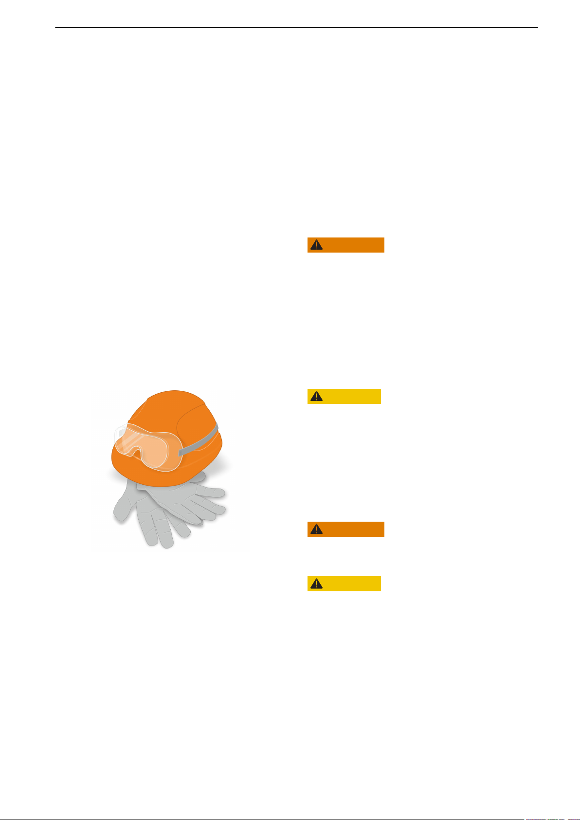
Personal safety equipment
CAUTION!
Always use appropriate safety equipment. Personal
protective equipment does not eliminate the risk of
injury but it will reduce the degree of injury if an
accident does happen.
Some examples are ear protection, eye and face
protection, protective footwear, personal protective
equipment, head protection, protective clothing,
gloves and respirators.
WARNING!
Ensure that all machine guards and safety devices are
in place and are functional.
CAUTION!
Never use tools or products that show signs of
damage.
47711262 01-2019 © AB VOLVO PENTA 5
Page 8
Safety Information
Protect your eyes
CAUTION!
Wear safety glasses.
Always wear safety glasses if there is a risk of
splintering, sparks and spray from the electrolyte (socalled battery acid), or other chemicals. Your eyes are
very delicate and damage can result in loss of sight!
Protect your skin
CAUTION!
Risk of skin damage.
Avoid getting oil on your skin! Prolonged or repeated
exposure to oil can dry out the skin. Thereafter,
irritation, dryness and eczema and other skin problems
may occur.
Use protective gloves and avoid oil-soaked clothes
and rags. Wash regularly, especially before eating.
Wear suitable protective creams to prevent skin from
drying out and to facilitate cleaning.
P0024470
Fire safety
WARNING!
Fire and Explosion Risk!
Accidental spark could ignite fuel vapors.
All fuels – as well as many lubricants and chemicals –
are flammable. Do not allow open flames or sparks
near them. Smoking forbidden! Hydrogen from the
batteries is also very flammable and explosive in
certain mixture with air.
Ensure that the workplace is well ventilated and take
the necessary precautions before welding or grinding
begins. Always ensure that there is a fire extinguisher
close at hand in the work area.
6 47711262 01-2019 © AB VOLVO PENTA
Page 9
Safety Information
Spare parts — safety
WARNING!
Always use spare parts with the same quality as
genuine Volvo Penta parts to minimize the risk of an
explosion or fire.
Components in fuel systems and electrical systems on
Volvo Penta engines are designed and manufactured
to minimize the risk of explosions and fire, in
accordance with applicable legal requirements.
Used oils, filters and chemicals etc.
WARNING!
Risk of fire.
Store fuel soaked rags and other flammable material
so that there is no danger of them catching fire.
Oil-soaked rags can spontaneously ignite under
certain circumstances.
P0024481
IMPORTANT:
Used fuel and oil filters are environmentally hazardous
waste and must be taken to an approved waste
management facility for correct handling, as must any
used lubricating oil, contaminated fuel, paint residue,
solvents, degreasers and wash residue.
Prevent start of the engine
WARNING!
Immobilize the engine by turning off the power supply
with the main switch(es) and lock it (them) in the off
position before starting work. Place a warning notice
at the main switch.
If the engine is equipped with BMS (Battery
Management System), always disconnect both battery
cables from the battery terminals.
Ventilation when running the engine
WARNING!
Only start the engine in a well-ventilated area. If
operating the engine in a closed area ensure that there
is exhaust ventilation leading out of the work area to
remove exhaust gases and crankcase ventilation
emissions.
The engine must not be operated in areas where there
are explosive materials or stored gas.
47711262 01-2019 © AB VOLVO PENTA 7
Page 10
Safety Information
P0024808
Rotating parts and hot surfaces
DANGER!
Working with or approaching a running engine is a
safety risk. Watch out for rotating components and hot
surfaces.
If the engine is in operation and operates another
device, you must not, under any circumstances,
staying close to the engine.
Work on running engines is strictly prohibited. There
are however adjustments that require the engine to be
run. Approaching a running engine is a safety risk.
Loose clothing and long hair can get caught in the
rotating parts; careless movements or a dropped tool
can lead to serious personal injury.
Be careful to avoid hot surfaces (exhaust pipes,
turbochargers, charge air manifolds, start elements
etc.) and hot fluids in pipes and hoses on engines that
are running or have just stopped. Re-install all
protective covers that were removed during
maintenance work before starting the engine.
P0024483
Information on the engine
IMPORTANT:
Make sure that all warning and information decals on
the product are always visible. Replace decals which
have been damaged or painted over.
Prohibition on use of start spray
WARNING!
Never use start spray or similar agents to start an
engine. This may cause an explosion in the inlet
manifold. Risk of personal injury.
8 47711262 01-2019 © AB VOLVO PENTA
Page 11
P0024688
Safety Information
Before start of engine
WARNING!
Never start the engine if there is reason to suspect fuel
and/or gas leaks, or if there is explosive material
nearby.
IMPORTANT:
Only start the engine with the air filter and protective
caps fitted. Foreign objects in the inlet line could cause
machine damage. Also make sure that no tools or other
parts have been left next to the engine.
WARNING!
Never start the engine with the valve cover removed.
There is a risk of personal injury.
For engines with turbochargers, the rotating
compressor turbine can in addition cause serious
personal injuries.
Before any work on the electrical system
WARNING!
Always stop the engine first. Then disconnect the
current at the main switches and any external power
supply before working on the electrical system – to
minimize the risk of electrical hazards.
IMPORTANT:
Never disconnect the current using the main switches
when the engine is running or by disconnecting the
battery cables.
The alternator and electronics could be damaged.
Avoid damage to the engine control
module and other electronics
IMPORTANT:
Switch off the main switch before connecting or
disconnecting a connector.
Before welding work
IMPORTANT:
Before any work with electric weld can begin, the
connection to all control units must be disconnected.
After finished welding, re-connect the connection to all
control units before connecting any battery cable.
Before any work on the cooling system
WARNING!
Stop the engine and let it cool before starting work on
the cooling system. Hot fluids and hot surfaces can
cause burns.
47711262 01-2019 © AB VOLVO PENTA 9
Page 12
Safety Information
P0024484
Risk of water penetration/sinking
WARNING!
If a launched boat is equipped with sea water tap and
safety valve, ensure that these are closed before any
work is allowed to begin on the cooling system.
Remember to open the tap and valve before starting
the engine!
Hot coolant under pressure
CAUTION!
Hot coolant can cause burns. Avoid opening the filler
cap for the coolant when the engine is still hot. Steam
or hot coolant can spray out and system pressure is
lost.
Open the filler cap slowly and release the pressure in
the cooling system if the filler cap or valve must be
opened – or if a plug or a coolant hose must be
removed from a hot engine.
Hot oil under pressure
CAUTION!
Hot oil can cause burns. Avoid getting hot oil on the
skin. Ensure that the lubrication system is not
pressurized before starting any work. Never start or
operate the engine without the oil filler cap is on. There
is a risk that hot oil can spray out.
Refueling
WARNING!
There is always a risk of fire and explosion during
refueling. Smoking is forbidden and the engine must
be stopped.
Proper fuel quality
IMPORTANT:
Always use the fuel recommended by Volvo Penta.
See Technical Data in Operator’s Manual. Other fuel
can damage the engine.
Wrong fuel quality can also lead to higher service
costs.
P0024477
10 47711262 01-2019 © AB VOLVO PENTA
WARNING!
Risk of personal injury.
Wrong fuel quality in a diesel engine can cause the fuel
control mechanism to bind which can cause the engine
to overspeed!
Page 13
P0024488
Safety Information
Legal requirements to use proper fuel
IMPORTANT:
To meet regulatory requirements for certified emission
levels must always recommended fuel according to
Technical Data in the Operator’s Manual be used.
At any leak detection on the fuel system
WARNING!
Wear safety goggles!
Be extremely careful when searching for leaks in the
fuel system high-pressure circuits. There is very high
pressure in the jet from pipes and injectors. The fuel
may penetrate the tissue and cause serious risk of
blood infection (septicemia).
Handling of fuel pipes
IMPORTANT:
High pressure pipes for fuel must not be bent or
straightened under any circumstances. Cracks may
occur. Damaged pipes must be replaced.
P0024468
Safe handling of batteries
WARNING!
Risk of fire and explosion. Never allow an open flame
or electric sparks near the batteries.
A spark caused by an incorrectly connected battery
can be enough for the battery to explode with serious
injuries.
Do not touch the connections during start attempts.
Sparking hazard! Do not lean over batteries.
Correct polarity of the batteries
IMPORTANT:
Make sure that the positive (+) and negative (–) battery
cables are correctly connected to the corresponding
battery terminals. Wrong connection may cause
severe damage to electrical equipment.
47711262 01-2019 © AB VOLVO PENTA 11
Page 14
Safety Information
Risks of electrolyte in batteries
WARNING!
Always wear protective goggles when charging or
handling batteries.
Battery electrolyte is highly corrosive.
Rinse immediately with copious amounts of water if the
electrolyte gets in your eyes. Search directly after the
rinsing help by medical staff.
If it comes electrolyte to unprotected skin, wash
immediately with soap and water.
Layout of the battery compartment
IMPORTANT:
Make sure the battery compartment is designed
according to current safety standards.
Cleaning the engine and components
P0024486
IMPORTANT:
Never use a high pressure washer for cleaning of
engine or engine components.
Cleanliness for sensitive components
IMPORTANT:
Observe meticulous cleanliness when handling
system components.
Even minimal amounts of dirt could cause a
breakdown.
Adjustment of the clutch
CAUTION!
Clutch adjustments must be carried out with the engine
stopped.
12 47711262 01-2019 © AB VOLVO PENTA
Page 15
Safety Information
Maneuvering
WARNING!
A rotating propeller can cause serious injury. Check
that nobody is in the water before engaging ahead or
astern. Never drive near bathers or in areas where
people could be in the water.
To avoid passengers falling overboard, refrain from
extreme and sudden rudder movements and ahead/
astern movements.
Lanyard switch
We recommend installing and using a lanyard switch
(optional), especially if the boat is capable of high
speeds. The lanyard switch stops the engine if the
driver looses control of the boat.
Accidents at sea
Maritime rescue statistics show that a large number of
boat accidents are caused by inadequate engine and
boat maintenance and the lack of safety equipment.
Make sure that the boat engine is properly maintained
by making sure that the recommended service is
performed, and that necessary safety equipment is
available and functional.
Stern turbulence
WARNING!
Carbon Monoxide Poisoning. When the boat moves
forward, an area of lower pressure air is formed behind
the boat — so-called turbulence. In certain conditions,
this turbulence can be powerful enough to draw the
exhaust fumes into the cockpit or cabin, creating a risk
of carbon monoxide poisoning to people on board.
The turbulence problem is most pronounced on tall,
broad-beamed boats with a transom stern. But even
for other boat types, low-pressure suction can be a
problem in certain conditions, such as driving with
cockpit awnings rigged. Other factors that can increase
the effect of turbulence are wind conditions, load
distribution, swell, trim, open hatches and ventilators
etc.
Most modern boats are, however, designed so that the
problem of low-pressure suction is very rare. Should
turbulence nevertheless occur, hatches or ventilators
must not be opened since this might exacerbate the
problem. Instead, try to change the speed, trim or load
distribution. If possible, take down or open the cockpit
awning. Contact your boat dealer for the best solution
for your boat.
47711262 01-2019 © AB VOLVO PENTA 13
Page 16

Safety Information
To remember before the boat trip
The lists below includes some tips on what to
remember to bring on any boat trip. The list can be
extended since the need for safety equipment varies
with the boat type and where or how it is used etc. We
recommend you ask a regional boat or sea safety
organization for more detailed maritime safety
information.
Take your chart out and study your planned route.
•
Calculate distance and fuel consumption. Listen to
weather reports.
Tell your friends/relatives about route plans if you
•
undertake a long journey. Remember to notify
changed plans or delays.
Inform everybody aboard about where the safety
•
equipment is located, and how it works. Make sure
that there is more than one person aboard who can
start and operate the boat safely.
Safety Equipment:
life jackets
•
communication equipment
•
emergency rockets
•
approved fire extinguisher
•
first aid kit
•
life buoy
•
anchor
•
paddle
•
flashlights
•
Spare Parts and Tools:
impeller
•
fuel filters
•
fuses
•
tape
•
hose clamps
•
engine oil
•
other tools that may be required
•
14 47711262 01-2019 © AB VOLVO PENTA
Page 17

Introduction
Check that you heave received the correct
operator’s manual before continuing reading. If
not, please contact your Volvo Penta dealer. Read
the Operator’s Manual carefully and learn to handle the
engine, controls and other equipment in a safe manner
before you start the engine.
For engine designations, refer to Technical
Data, page 79. The designation is stated on the
engine plate, refer to Technical Data, page 84.
The illustrations in this book may cover several product
types, which means that there may be slight
differences between the illustrations and the
purchased product. This does, however, not affect the
validity of the information and/or instructions in the
manual. Volvo Penta reserves the right to make
alterations to specifications, design features, and
illustrations without prior notice.
At service, software can be updated that affects the
functionality described in this manual.
About this Manual
This Operator's Manual has been prepared to give you
the greatest possible benefit from your Volvo Penta
marine engine. It contains necessary information
regarding safe and correct engine operation and
maintenance.
Always have the Operator's Manual available. Store it
safely and do not forget to hand it over to the next
owner if you sell your boat.
47711262 01-2019 © AB VOLVO PENTA 15
Page 18

Introduction
Warranty
Your new Volvo Penta marine engine is covered by a
limited warranty, subject to the conditions compiled in
the Warranty Information. Note that AB Volvo Penta’s
liability is limited to the specification in the Warranty
Information (included CD) and Emission Control
System Warranty Statement.
Read the information carefully, as soon as possible
after delivery. It includes important information about
service and maintenance; the owner is responsible for
being familiar with, checking and implementing these.
Otherwise AB Volvo Penta may deny its warranty
obligations in part or in full.
NOTICE! Make sure that a Commissioning has been
carried out on your Volvo Penta engine. This should be
done together with your Volvo Penta dealer when
finalizing the purchase. Without a proper
Commissioning registration the warranty will not be
valid.
Contact your Volvo Penta dealer if you have not
received the Warranty Information or Service
Book.
Your New Boat
Carefully read through the instructions and other
information that is delivered with the new boat. Learn
to handle the engine, controls and other equipment in
a safe and proper manner. If this is your first boat or if
the boat type is unfamiliar to you, we recommend that
you practice maneuvering the boat before casting off
on the maiden voyage. Make yourself familiar with the
boat’s seakeeping and maneuvering qualities at
different speeds, sea states and load conditions.
Bear in mind that a person in charge of a boat under
way bears the legal responsibility of knowing and
following the regulations for passage and safety afloat.
Learn which regulations apply to you and your waters
by contacting the relevant authorities or maritime
safety organization. We recommend that you complete
a boat driver’s course.
Running in the engine
The engine must be run in during the first 10 hours of
operation. Do this by using the engine in normal
operation, where full load is only applied for short
periods of time. Never run the engine at constant
speed for any longer periods of time.
Since oil consumption is higher during the running in
period, be sure to control the oil level more frequently
than normally recommended. See Maintenance for
more information.
16 47711262 01-2019 © AB VOLVO PENTA
Page 19

Introduction
Fuel, oils and coolant
Only use the fuels and oils recommended in the
Operator’s Manual, since other grades may cause
malfunctions, increased fuel consumption and
possibly shorten the life of the engine.
Always change the oil, oil filters and fuel filters at the
specified maintenance intervals.
Make sure to always use suitable and correctly mixed
coolant.
Future warranty claims related to engine and
accessories may be denied if an unsuitable coolant
has been used, or if the instructions for coolant mixture
have not been followed.
Maintenance and replacement parts
Volvo Penta engines are designed for maximum
reliability and long life and built to withstand a
demanding environment. The engines are also
designed to have a minimal environmental impact.
These qualities will be maintained through regular
servicing and the use of spare parts with the same
quality as genuine Volvo Penta parts. If reliable and
purpose-built parts are not used, your safety, health,
and the machine’s function may be compromised.
Volvo Penta has a world-wide network of authorized
dealers.
The authorized dealers are Volvo Penta product
specialists, and have the accessories, genuine parts,
test equipment and special tools needed for high
quality service and repair work. Always observe the
maintenance intervals in the manual, the complete
Service Protocol can be found at volvopenta.com.
Remember to note the engine / transmission
identification number when you order service and
spare parts.
47711262 01-2019 © AB VOLVO PENTA 17
Page 20

Introduction
Excessive strain on a product and
components
Volvo Penta products and components are not
dimensioned for external loads. Never stand or step
onto an engine, transmission or its components. Loads
can bring about damage and the malfunction of a
product or property.
Volvo Penta EVC system, integrity
and modification
The Electronic Vessel Control (EVC) system is a
complete vessel control system for engine, gear, and
vessel steering control. Modifying the EVC system or
connecting spare parts or systems that do not comply
with the quality of genuine Volvo Penta parts may
adversely affect the system performance, safety, and
warranty coverage.
Volvo Penta recommends only the use of electronic
systems and spare parts with the same quality as
genuine Volvo Penta parts. Contact your local Volvo
Penta dealer for detailed information and advice.
18 47711262 01-2019 © AB VOLVO PENTA
Page 21

Introduction
Environmental care
Environmental care is a core value at Volvo Penta.
Energy efficiency and low emissions are among the
most important product related aspects and priority
focus areas for Volvo Penta business. Several of the
global challenges the world faces are directly or
indirectly related to power industries and transports.
We recognize that Volvo Penta is part of the
environmental problems, but we are also convinced
that we are a part of the solution.
Volvo Penta currently has a broad engine program in
which great advances have been made in reducing
exhaust emissions in the same time as the fuel
consumption has been improved. Through regular
maintenance, the Volvo Penta engines retain its low
fuel consumption and low emissions. We hope that you
will be keen to preserve these qualities.
Always follow the directions in the Operator’s Manual
regarding fuel grades, operation and maintenance to
avoid unnecessary environmental impact. Contact
your Volvo Penta dealer if you notice any changes
such as increased fuel consumption or exhaust smoke.
Remember always to hand in environmental
hazardous waste such as drained oil, coolant, old
batteries, etc. for treatment at a recycling facility. Our
united efforts can make a valuable contribution to the
environment.
Recording engine data
One or more computers in your Volvo Penta engine
can record detailed information. Data — such as usage
and information of other systems and modules on the
engine — can be included. This data can include information such as boat position and usage. Only a limited amount of data can be stored.
AB Volvo Penta and authorized workshops will not
distribute this stored information without permission.
AB Volvo Penta may, however, be forced to provide
this information if required by national legislation. In
general, AB Volvo Penta and authorised workshops
may read and use the information.
47711262 01-2019 © AB VOLVO PENTA 19
Page 22

Introduction
Certified Engines
If you own an emission-certified engine used in an
area where exhaust emissions are regulated by
law, this places special demands on the care and
maintenance you provide your engine.
NOTICE! Neglects or failure to follow the points listed
here may invalidate the engine emission certificate.
This means AB Volvo Penta can no longer guarantee
engine conformity with the certified model. Volvo Penta
is not responsible for damages or costs arising as a
result of this.
Certification means that an engine type has been
•
checked and approved by the relevant authority.
The engine manufacturer guarantees that all
engines of the same type are equivalent to the
certified engine.
It is the responsibility of the operator/user to ensure
•
that no intentional misuse of the engine takes place.
Volvo Penta maintenance and service intervals
•
must be complied with.
Any case of malfunction must be rectified without
•
delay.
Only use genuine Volvo Penta parts or spare parts
•
with the same quality as genuine Volvo Penta parts.
Volvo Penta recommends that service to injection
•
pumps, pump settings and injectors always are
carried out by a qualified workshop.
The engine must not be converted or modified in any
•
way, except with accessories and service kits that
Volvo Penta has approved for the engine.
No installation changes to the exhaust pipe and
•
engine air inlet ducts may be made.
No warranty seals (where present on the product)
•
may be broken by unauthorized persons.
The general instructions in the Operator's Manual
•
concerning operation, service and maintenance
apply.
20 47711262 01-2019 © AB VOLVO PENTA
Page 23

Introduction
Volvo Penta Dealer Network
The Volvo Penta global network of authorized dealers
is at your service. We strongly recommend that you
take your product to an authorized Volvo Penta dealer
for service and repair. They are specialists in Volvo
Penta products and have the accessories, genuine
Volvo Penta parts, the special tools and the latest
service information for high quality service and repair
work.
Dealer Locator Services
Locate the nearest Volvo Penta dealer through our
dealer locator on www.volvopenta.com or download
the dealer locator app to your smartphone.
Volvo Penta Action Service
Our global dealer network, your first line of contact, is
backed up by Volvo Penta Action Service, a phone
based breakdown and support service providing
assistance 24 hours a day, every day of the year.
How it works
A dedicated operator will support you all the way
through your case and keep you updated on status and
progress.
Whenever on-site assistance or technical support is
needed, the operator will put you in contact with the
closest Volvo Penta dealer that can support your
product.
Phone numbers
Find your Volvo Penta Action Service phone number
and more information on www.volvopenta.com.
47711262 01-2019 © AB VOLVO PENTA 21
Page 24
Instruments and Controls
This chapter describes the instruments, panels and controls Volvo Penta sells for your engine.
If you would like to complement your instrumentation, or if your boat is equipped with instruments not described
here, we ask that you contact your Volvo Penta dealer.
Ignition Lock
The system lacks a start lock. Therefore, the helm
station should be lockable, or alternatively a lockable
main switch should be fitted, to prevent unauthorized
engine start.
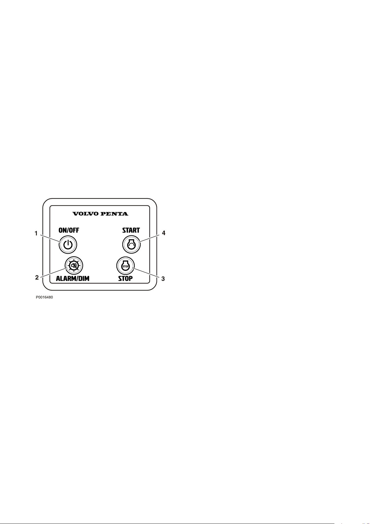
Start/Stop Panel
Control Panel
On/Off button (1)
Depress the button to start or stop the system.
The panel cannot be switched off when the engine is
running.
Start button (4)
When the button is depressed the pre-heat function is
activated and the start motor engaged.
Multi-function button (2)
Confirm the alarm. If an alarm occurs, a flashing
•
warning symbol will be displayed in the tachometer
window and an audible alarm will sound.
The alarm is confirmed by depressing the multifunction button. The audible alarm is silenced and
the warning symbol is lit continuously until the fault
is remedied.
Backlighting. To switch tachometer window
•
backlighting on or off, depress the button for 1 - 5
seconds.
The backlighting can be adjusted in five steps by
depressing the button for less than 1 second.
Adjust the tachometer window contrast by holding
•
down the button for more than 5 seconds.
Stop button (3)
The engine stops running when the button is
depressed.
22 47711262 01-2019 © AB VOLVO PENTA
Page 25
AUX
1
2
3
4
5
6
7
8
9
0
3
2
1
4
RPMX1000
P0007517
Instruments and Controls
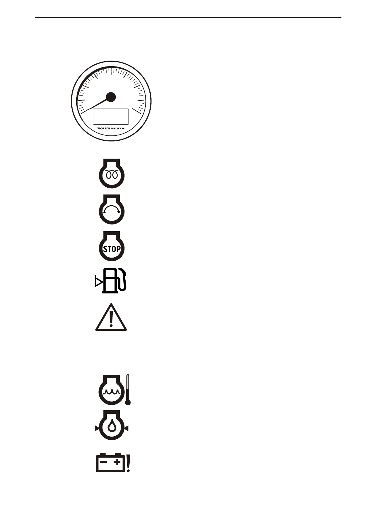
Gauges
Tachometer
The tachometer shows engine speed; multiply the
value shown on the dial by 1,000 to get the number of
engine revolutions per minute.
Operating information is displayed in the tachometer
window.
Operating information symbols
1 Pre-heating
The pre-heat symbol is displayed when the glow
function is active.
2 Starting
The start symbol is displayed when the start motor
is engaged.
3 Stopping
The stop symbol is shown when the stop button is
depressed.
4 Fuel level
If a fuel level sensor is installed (accessory) the fuel
level symbol is displayed when there is around 20%
of fuel remaining in the tank.
The engine must run for at least one minute before
the function is activated.
5 System fault
The system fault symbol lights up in the case of
short circuits or cable breaks.
6 Auxiliary alarm
Auxiliary alarm for accessory sensors.
7 Coolant temperature
47711262 01-2019 © AB VOLVO PENTA 23
The coolant temperature symbol lights up if the
engine coolant temperature is too high.
8 Oil pressure
If the oil pressure lamp lights up during operations,
the engine oil pressure is too low.
9 Charging
The charging lamp lights up if the alternator stops
charging.
Page 26
1
P0007518
Instruments and Controls
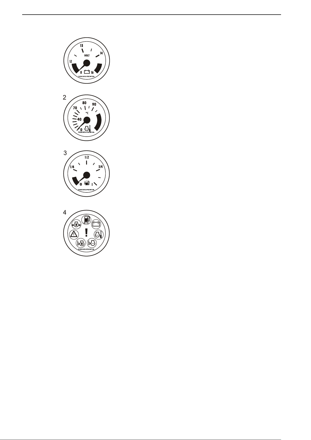
Optional instruments
These instruments are sold as engine accessories by
Volvo Penta.
1 Voltmeter, battery charging
The meter shows the alternator charge current.
During operations the charge voltage must be
around 14 V. When the engine is stopped and
electrical power switched on, battery voltage is
around 12 V.
2 Coolant temperature gauge
The instrument shows engine coolant temperature.
During operations coolant temperature must
normally be between 75-95°C (167-203°F).
3 Fuel level gauge
The fuel level gauge shows the quantity of
remaining fuel.
4 Alarm monitor
The alarm monitor gives a visual warning to call
attention to any alarms that occur.
24 47711262 01-2019 © AB VOLVO PENTA
Page 27
1 2
3
4 5
G H
P0001168
0
ENGINE HOURS
HOURS
P0003010
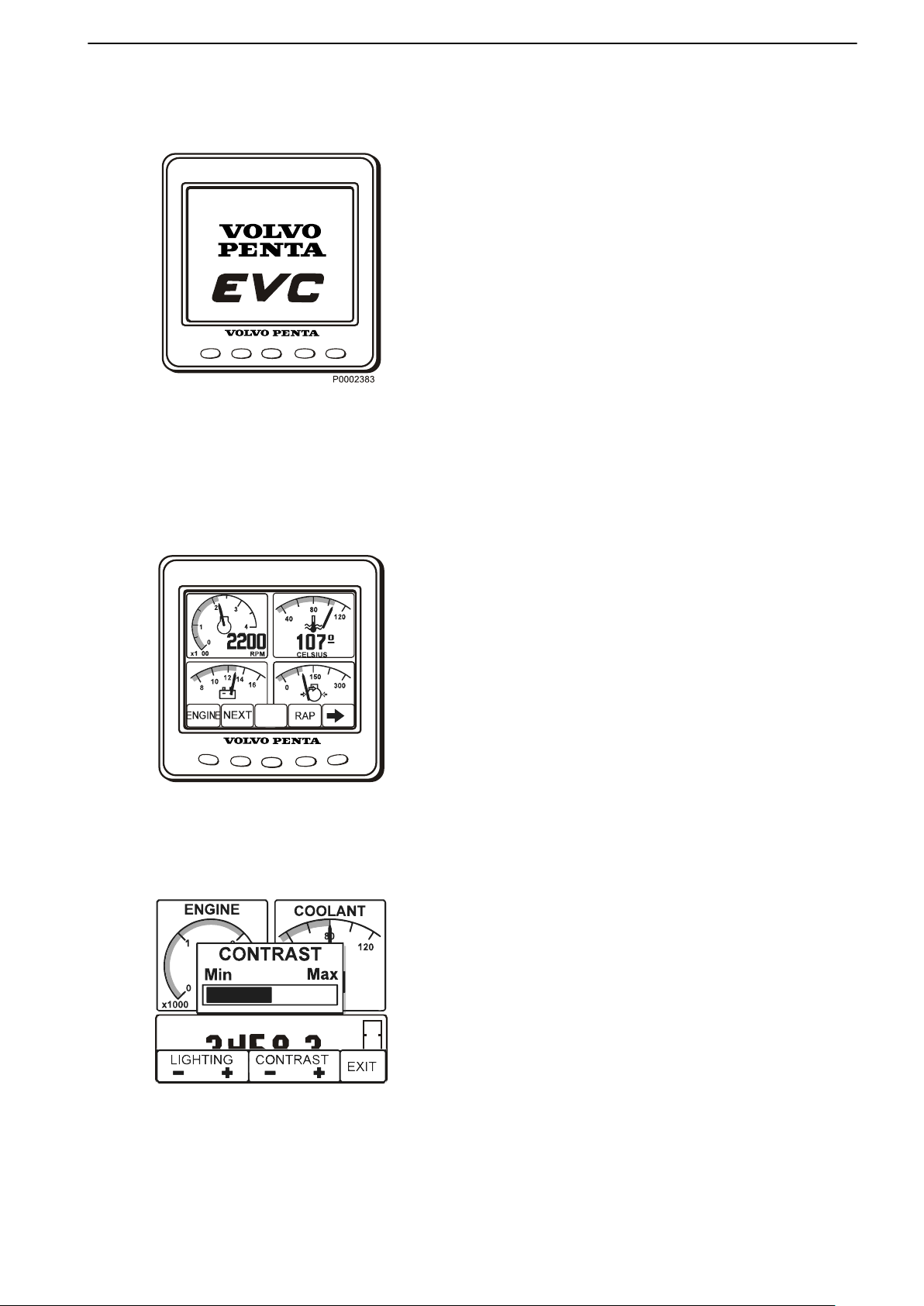
Instruments and Controls
EVC system display
It is possible to present several windows with different
operational information in the EVC system display. The
various screens are selected using the instrument
buttons.
Before the display is put to use certain settings must
be entered in the configuration menu; refer to
Configuration menu.
It is also possible to bring up a menu identical to that
shown in the tachometer display by navigating to
System information in the Configuration menu, or by
depressing button 2; refer to Multi, button 2.
A self-test is performed at start; the display will emit a
constant audible signal if a fault is detected. The
display will continue to function, but may behave in
unexpected ways.
Only installed functions are shown in the display.
Screens
Depress any of the buttons 1 to 4 to bring up the
function menu for the buttons on the lower part of the
display.
Buttons 1, 2 and 4 provide different screens.
Button 1 – Engine
Button 2 – Multi
Button 4 – Graph
Use button 5 to adjust contrast and to access the
configuration menu for display settings; refer to
Configuration menu.
Exit the menu by waiting a few seconds or by
depressing button 5 (EXIT).
Contrast
The display has five contrast settings. Depress button
5 (far right) and change the contrast by depressing +
(button 4) or – (button 3).
Store the setting by depressing EXIT (button 5).
47711262 01-2019 © AB VOLVO PENTA 25
Page 28
P0007392
P0003011
Instruments and Controls
Engine, button 1
Engine revolutions and speed are shown in the upper
part of the window. Operating hours are displayed in
the lower part, along with a fuel level indicator if this
function is installed.
If speed information is lacking, coolant temperature will
be shown instead.
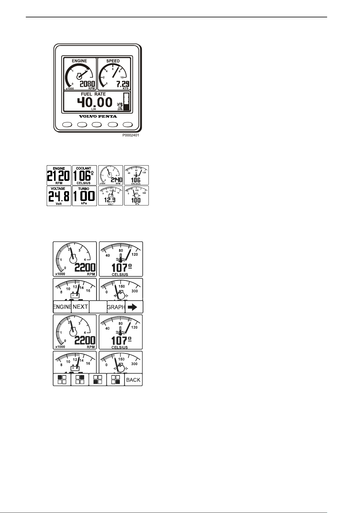
Multi, button 2
Operational information is displayed in four analog or
digital windows in the multi screen. The display can
either show several windows, or be divided so that the
lower part shows System information. To switch
between the different screens depress button 2
repeatedly.
If the selected information is lacking, the symbol “—”
will be displayed: for analog instruments the dial will be
absent.
Selecting screens
Depress the right arrow (button 5) to select the
information to be displayed in each respective window.
Then repeatedly depress the button that corresponds
to the window to be set until the desired information is
shown.
The type of information accessible depends on the
type of electrical system and sensors the boat is
equipped with.
26 47711262 01-2019 © AB VOLVO PENTA
Page 29

4000
2000
P0002420
Instruments and Controls
Graph, button 4
This screen displays operational information in the
form of graphs. Depress button 4 repeatedly to select
the information to be displayed. To set the time interval,
refer to Configuration menu.
If contact with the system is lost, a straight line will
proceed across the screen.
Configuration menu
Open the Configuration menu by holding down button
5 for at least 3 seconds. In this screen it is possible to
retrieve System information, enter various display
settings, calibrate depth compensation and speed and
retrieve other system information.
Engine ignition must be switched on when changing
display settings or calibrating functions.
Navigate through the menu using the up and down
arrows, and select using the right arrow.
System Information
This screen shows the same information as that shown
in the tachometer display; refer to Instruments and
Controls, page 23 for further information.
Alarm
When the system detects a fault, the display
automatically switches to the System Information
screen. For further information, refer to Fault
handling, page 41.
47711262 01-2019 © AB VOLVO PENTA 27
Page 30

P0003002
Instruments and Controls
Settings
Language: setting the display language.
Bleep: setting button bleep On or Off.
Engine: setting the installation the display forms part
of, and the engine to be shown in the display (single,
port, starboard or twin).
Eng. series: setting the engine series for the display
(D1/D2, <D2). The display is factory set for engines
larger than D1/D2, therefore the display must be re-set
before it can be used on D1/D2 engines.
Display: setting speed indicator and tachometer
intervals.
- Rpm intervals, 2500–9000 rpm in 500 rpm stages.
Set 4000 rpm.
- Speed, on/off.
- Speed intervals, 10–100 knots in 10 knot stages.
- Graph intervals: 2 min, 10 min, 30 min, 60 min, 2 h,
4 h or 8 h.
- Speed (Speed): KNOTS, MPH, KM/H
Units: Selection of operational information units to be
shown (this menu is only displayed if “Local” is selected
in the settings menu: “Local” must always be selected
for D1/D2 engines).
- Distance: NM, MILE, KM
- Oil pressure/Turbo pressure: kPa, psi
- Fuel rate: L/H, GAL/H, IGAL/H
- Temperature: °C, °F
Calibration: the engine must be switched on during
calibration.
Depth compensation
Setting the Volvo Penta echo sounder. The echosounder can be installed anywhere between the
waterline and the boat's deepest point. Set the
deviation – off set – so that the display value shows
one of these points.
To adjust the value up (+), set the distance between
the echo-sounder and the waterline; to adjust the value
down (–), set the distance between the echo-sounder
and the boat's deepest point. The value can be set in
0.1 unit stages.
Store the set value by depressing BACK (button 5).
28 47711262 01-2019 © AB VOLVO PENTA
Page 31

P0003005
Instruments and Controls
Speed factor
The speed factor must be set while the boat is under
way. Compare the displayed boat speed value with
GPS data (or another boat) and adjust the speed factor
until the values agree.
The speed sensor calibration value can be adjusted
upwards (+) or downwards (-) in stages of 0.01 units
(+ or - 1%). Store the adjusted value by depressing
BACK (button 5).
47711262 01-2019 © AB VOLVO PENTA 29
Page 32

N
F
R
T
T
1
P0002427
Instruments and Controls
Controls
This section describes the controls Volvo Penta sells
for your engine. Contact your dealer if your boat is
equipped with controls other than those described
here, and you feel uncertain about their function.
Maneuvering
A single-lever control operates both gearshift and
throttle functions from the same lever.
The engine can only be started with the control lever
in the neutral position.
N = Neutral position. Reverse gear/drive
disengaged and engine at idle.
F = Reverse gear/drive engaged for movement
ahead.
R = Reverse gear/drive engaged for movement
astern.
T = Engine rpm control (throttle).
Disconnecting the gearshift function
The gearshift function can be disconnected so that the
control lever only operates the throttle.
1 Put the control lever in neutral (N).
2 Depress the neutral button (1), and keep it
depressed at the same time as the lever is
moved forward.
3 Release the neutral button, the shift function is
disengaged and the lever only influences engine
revolutions.
The gear shift function is reconnected automatically
when the lever is returned to the neutral position.
CAUTION!
Take care not to engage the gear by mistake.
30 47711262 01-2019 © AB VOLVO PENTA
Page 33

Instruments and Controls
Adjusting the friction brake
The lever is fitted with a friction brake to allow
adjustment for easier or stiffer movement as required.
The friction brake only affects movement of the throttle
control lever.
1 Lift away the cover from the control. On side-
mounted controls the lever must be removed first.
2 Move the lever to the half throttle/astern position.
3 Adjust the friction brake by turning the screw
clockwise (+) for stiffer lever movement, and
counterclockwise (-) for easier movement.
4 Replace the cover and the lever.
47711262 01-2019 © AB VOLVO PENTA 31
Page 34

Starting
Make a habit of visually checking the engine, engine bay and transmission before start. This will help you to
discover quickly if anything abnormal has occurred, or is about to occur. Also check that instruments and warning
displays show normal values when you have started the engine.
To minimize cold start smoke we recommend you install an engine heater or engine bay heater if temperatures
below +5°C (41°F) are encountered.
WARNING!
Never use start spray or similar agents to start an engine. This may cause an explosion in the inlet manifold. Risk
of personal injury.
Before Starting
Check the engine and transmission oil levels.
•
Check coolant level.
•
Open the sea cock.
•
Open the fuel cock.
•
Turn the main switch(es) on.
•
IMPORTANT:
Never disconnect the current using the main
switches when the engine is running or by
disconnecting the battery cables.
The alternator and electronics could be damaged.
Start the engine bay fan, where fitted, and allow it to
•
run for at least four minutes.
Check that there is sufficient fuel for the planned trip.
•
32 47711262 01-2019 © AB VOLVO PENTA
Page 35

!
!
+
-
0
3
2
1
4
RPMX1000
P0008437
Starting
Starting the Engine
Activate the control panel by depressing the on/off
button (1). The Volvo Penta logo is displayed in the
window. Two audible signals are sounded to indicate
the system is ready and that the engine may be started.
Check the tachometer
If an operational fault occurs an audible alarm will
sound and a symbol will flash in the tachometer
window. Refer to theFault handling, page 41 chapter
for more detailed information and recommended
actions.
Check the alarm instrument (accessory).
The lamps in the alarm instrument light up each time the
ignition is turned on. Check that all lamps light up and
then extinguish. If any lamp flashes, a fault has been
registered; refer to the Fault handling, page 41 chapter
for more detailed information and recommended
actions.
Start the engine
Press the start button (4). Release the start button as
soon as the engine starts.
The pre-heating symbol is displayed in the tachometer
window. Pre-heating is automatic and lasts for 20
seconds.
Pre-heating only takes place if engine temperature is
below 50° (122° F).
Pre-heating may be activated before the engine is
started by depressing the start button (4) for a short
moment. Pre-heating will continue for 20 seconds. The
pre-heating symbol is displayed in the tachometer
window.
47711262 01-2019 © AB VOLVO PENTA 33
Page 36

Starting
Overheating Protection
If the starter motor is engaged for its maximum
activation time (30 seconds), the starter motor circuit
is cut automatically to protect the starter motor from
overheating. If possible, leave the starter motor to cool
for at least five minutes before making a new start
attempt.
Read off the instruments and warm up the
engine
Allow the engine to idle for the first 10 seconds. Read
off the instruments and check that they show normal
values. Check that no warning lamps are flashing. If
any lamp flashes, a fault has been registered; refer to
the Fault handling, page 41 chapter for more detailed
information and recommended actions.
Warm up the engine at low speed and low load, so that
normal working temperature is reached before full
power is applied.
34 47711262 01-2019 © AB VOLVO PENTA
Page 37

Operation
Learn to handle the engine, controls and other equipment in a safe and proper manner before casting off on your
maiden voyage. Remember to avoid sudden and extreme rudder maneuvers and gear shifts. There is a risk for
passengers and crew falling over or falling overboard.
WARNING!
A rotating propeller can cause serious injury. Check that nobody is in the water before engaging ahead or astern.
Never drive near bathers or in areas where people could be in the water.
Reading the Instruments
Read off the instruments and alarm display
immediately after start, and then regularly during
operation.
Alarms
If an alarm is tripped, an audible alarm will sound and
a symbol will flash in the tachometer window (1).
If optional equipment such as alarm instruments or an
EVC display are installed, the relevant warning lamp
will flash there also.
1 Reduce engine speed to idle.
2 Cancel the alarm by depressing the multi-function
button (2).
The audible alarm will be silenced. The symbol will
be lit continuously until the fault is remedied
3 Take the necessary action: refer to the Fault
handling, page 41 section.
47711262 01-2019 © AB VOLVO PENTA 35
Page 38

1
2
3
P0005856
Operation
Maneuvering
Shifting between ahead and astern must be done at
idle revolutions. Shifting at higher revolutions can be
uncomfortable for those on board and cause
unnecessary stress to the transmission or make the
engine stall.
Always shift between ahead and astern in
the following manner:
1 Reduce engine revolutions to idle and allow the
boat to lose most of its speed.
2 Move the control lever to the neutral position with
a quick, firm movement. Pause a moment.
3 Move the control lever back with a quick, firm
movement and increase revolutions.
36 47711262 01-2019 © AB VOLVO PENTA
Page 39

Operation
Sailing
When sailing, set the control lever to astern if a folding
propeller is fitted.
If a fixed propeller is fitted the control lever should be
set to neutral or reverse. When using a fixed propeller
and sailing with the control lever set to reverse the
speed is slowed down though less noise is being
made.
IMPORTANT:
If a fixed propeller is fitted the engine needs to be
started and kept running for five minutes every fourth
hour of sailing to avoid problems with the transmission
system. The control lever must be set to neutral during
the whole procedure.
Cruising Speed
Avoid operations at full throttle for best fuel economy.
We recommend a cruising speed that is around
500-1000 rpm below the maximum rpm at top speed
(full throttle).
Depending on the type of hull, choice of propeller, load
and sea state etc., maximum revolutions at top speed
may vary, but should be within the full throttle range;
refer to the Engines section.
47711262 01-2019 © AB VOLVO PENTA 37
Page 40

Engine Shutdown
Allow the engine to run at low idle, in neutral, for a few minutes after operations are completed. In this way afterboiling is avoided at the same time as temperature equalization takes place. This is especially important when
the engine has been run under heavy load at high rpm .
Stop the Engine
Press the Stop button (3) until the engine stops
running.
Press the On/Off button (1) to cut the power to the
system.
If the engine is stopped and the ignition still turned on,
an alarm sounds after 10 seconds to prevent the
ignition is left on unintentionally and the battery will
become discharged.
Silence the alarm by turning the ignition off, or reset
the alarm with the multifunction button (2) if the ignition
is to be turned on.
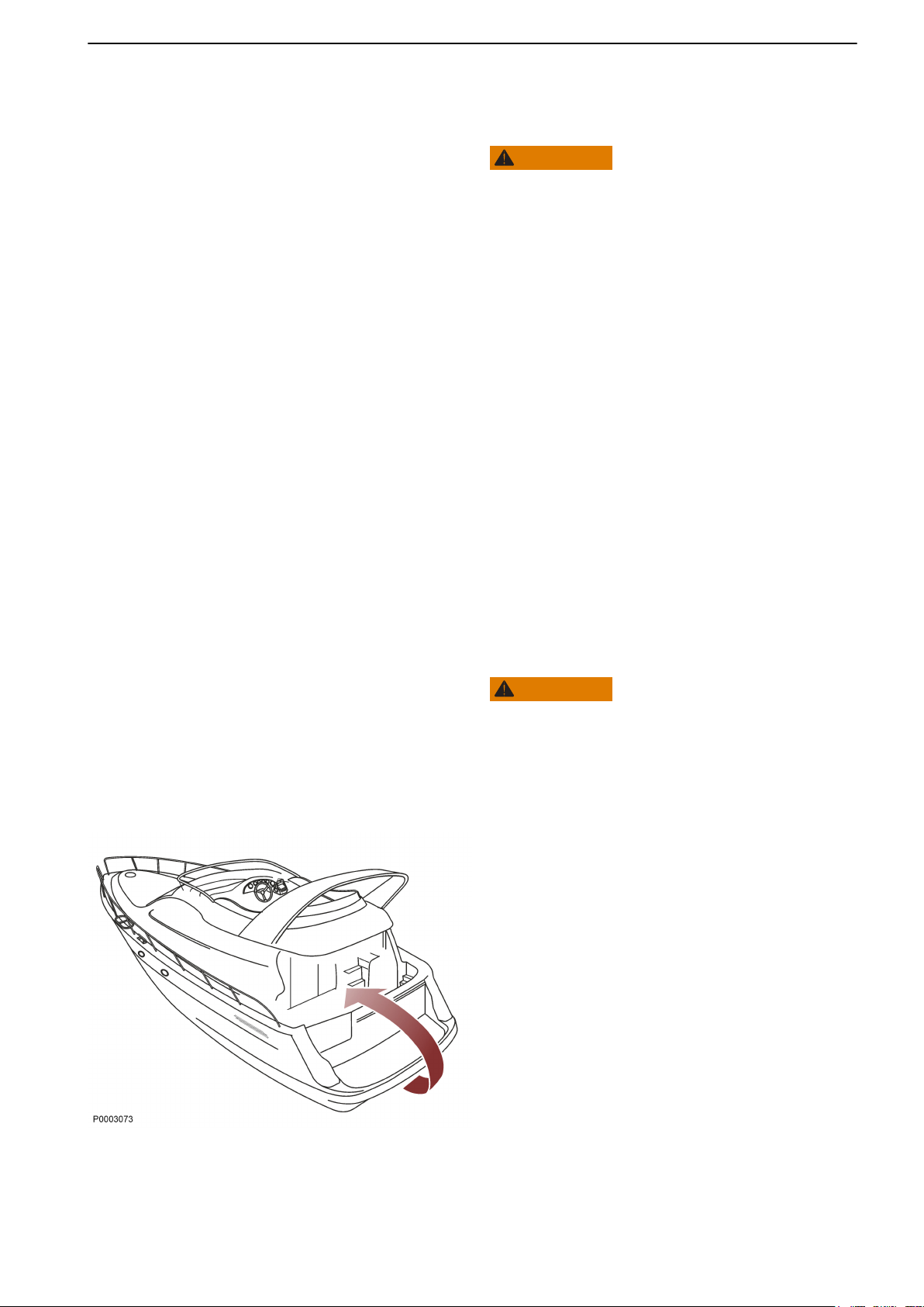
Auxiliary stop
If the engine cannot be stopped in a normal procedure,
it is possible to stop the engine via the auxiliary stop
(A) mounted on the side of the engine.
38 47711262 01-2019 © AB VOLVO PENTA
Page 41

Engine Shutdown
After Engine Shutdown
Check the engine and engine bay for leakages.
•
Close the fuel tap.
•
Close the sea cock where fitted.
•
Take an hour meter reading and carry out
•
preventive maintenance according to the
maintenance schedule.
Boats with stern drives: Trim the stern drive down to
•
maximum to protect the trim ram piston's untreated
surfaces from fouling.
If there is a risk of the boat striking bottom with the
stern drive, the drive must instead be trimmed up to
the maximum lift position.
Turn off the main switch before any long stoppage.
•
NOTICE! Depending on the model and setup, there
could be more than one switch.
NOTICE! Do not turn off the main switch within 30
seconds after turning off the ignition. This in order to
save engine data to the engine control unit.
47711262 01-2019 © AB VOLVO PENTA 39
Page 42

Engine Shutdown
Operation break with the boat in water
If the boat is not used, but left in the water, the engine
must be warmed up at least once every fortnight. This
prevents corrosion damage in the engine.
If you expect the boat to be unused for two months or
more, it must be inhibited, please refer to
Storage, page 75
Operation break with the boat out of water
Where boats are kept laid up on land when not in use,
there is a lower level of galvanic corrosion protection
due to oxidation on the sacrificial anodes. Before
launching the boat the sacrificial anodes on the drive
and shield must be cleaned with emery paper to
remove any oxidation.
If you expect the boat to be unused for two months or
more, it must be inhibited, please refer to
Storage, page 75.
IMPORTANT:
Use emery paper. Do not use a wire brush or other
steel tools when cleaning, as these may damage the
galvanic protection.
Cold Weather Precautions
If the engine bay cannot be kept frost free, the sea
water system must be drained and the freshwater
system coolant must have sufficient freeze protection
to prevent freeze bursting; refer to
Maintenance, page 58 and Seawater System,
Draining, page 61 respectively for more detailed
information.
Check the charge status of the battery. A poorlycharged battery can freeze and burst.
40 47711262 01-2019 © AB VOLVO PENTA
Page 43

Fault handling
0
3
2
1
4
RPMX1000
SYSTEM INFORMATION
1
ON/Off START
ALARM/DIM STOP
2
P0016957
Despite regular maintenance according to the maintenance schedule and perfect operation conditions, faults that
need to be attended to during travel, may occur. This chapter describes some possible alarms and fault handling.
Note that the content of this chapter does not provide full coverage of the possible fault messages and alarms.
Contact a Volvo Penta workshop for assistance with diagnostic readouts and unresolved faults.
If an operational fault arises an audible alarm will
sound and a symbol will flash in the tachometer
window(1) If optional equipment such as an alarm
monitor or an EVC display are installed, the relevant
warning lamp will flash there also.
Cancel the alarm by depressing the multi-function
button (2). The audible alarm will be silenced. The
symbol will be lit continuously until the fault is
remedied.
This chapter describes faults and actions to be taken.
CAUTION!
Read the safety precautions for maintenance and
service in the Maintenance Safety Information
chapter before starting work.
47711262 01-2019 © AB VOLVO PENTA 41
Page 44

Fault handling
Coolant Temperature
The coolant temperature lamp is lit if the coolant
temperature is too high.
IMPORTANT:
Continued operations with too-high engine
temperature can cause serious engine damage.
• Check coolant level. Refer toCoolant Level,
Checking and Topping Up, page 59.
• Check that the raw water filter, where such is
fitted, is not clogged. Refer to Seawater Filter,
Check and Cleaning, page 64.
• Check the impeller in the sea water pump. Refer
toImpeller, Check and Change, page 62.
If the alarm continues despite the above actions being
carried out, run the engine at low revolutions and drive
the boat to the nearest service workshop for repair.
Oil pressure
If the oil pressure lamp lights up during operations, the
engine oil pressure is too low.
IMPORTANT:
Continued operations with too-low oil pressure
causes serious engine damage.
• Checking Engine Oil Level, refer to Oil level,
checking and topping up, page 55.
• Check that the oil filter is not blocked. Change
the oil filter as necessary; refer to Engine oil and
engine oil filter, changing.
• Contact a Volvo Penta workshop if the fault
remains.
Battery
The charging lamp lights up when the alternator stops
charging the batteries, which may result from a fault
in the electrical system or the need to tension the
alternator drive belt.
• Check belt tension. Refer to Drive belt, check
and change, page 53.
• Check to see if there are no short circuit, chafed
wires or wires with loose connections.
• Check the fluid level in the battery; refer to
Battery, page 66.
• Contact a Volvo Penta workshop if the fault
remains.
42 47711262 01-2019 © AB VOLVO PENTA
Page 45

Fault handling
System failure
The "system fault" symbol is displayed when there is
a short circuit or cable break.
The symbol shows if the ignition is left on, refer to
Engine Shutdown, page 38.
• Check to see if there are any chafed wires or
wires with loose connections.
• Contact a Volvo Penta workshop if the fault
remains.
Fuel Level
The fuel level symbol is displayed when less than 20%
fuel remains in the tank if a fuel level sensor is
installed (optional equipment).
Auxiliary alarm
Alarm for auxiliary sensors (optional equipment).
Alarm handling display (optional
instrument)
1 The fuel level symbol lights up during operation
when less than 20% fuel remains in the tank if a
fuel level sensor is installed (optional
equipment).
2 The battery lamp lights up if the alternator is not
charging.
3 The coolant temperature lamp lights up when
the coolant temperature is too high.
4 This indicator is not activated for the engine.
5 This indicator is not activated for the engine.
6 The "System Failure lamp" will light up at short
circuit, broken wire and AUX failure.
7 If the oil pressure lamp lights up during
operation, the oil pressure in the engine is too
low.
47711262 01-2019 © AB VOLVO PENTA 43
Page 46

Fault handling
Fault Tracing
A number of symptoms and possible causes of engine malfunctions are described in the table below. Always
contact your Volvo Penta dealer if any problems occur which you cannot solve by yourself.
NOTICE! Read the safety regulations for care and maintenance in the Safety precautions for maintenance and
service operations chapter before work you start work.
Symptoms and possible causes
Start motor will not turn, or turns slowly 1, 2, 26
Engine does not start 3, 4, 5, 6, 7, 8, 27
Engine starts but stops again 5, 6, 7, 8
Engine is difficult to start 5, 6, 7, 8
Engine does not reach correct operating speed at full throttle 6, 7, 8, 9, 10, 11, 12, 17
Engine knocks 13
Engine runs roughly 5, 6, 7, 8, 12, 13
Engine vibrates 17, 18
High fuel consumption 9, 10, 12, 14, 17
Black exhaust smoke 4, 12, 14, 17
Blue or white exhaust smoke 14, 24
Lubrication oil pressure too low 15, 16
Coolant temperature too high 19, 20, 21, 22, 23
No charge, or poor charge 1, 25
1. Flat battery
2. Poor contact/open circuit in cables
3. The stop lever is pulled out
4. Insufficient preheat
5. Lack of fuel
6. Blocked air filter
7. Air in the fuel system
8. Water/contamination in fuel
9. Boat abnormally loaded
10. Fouling on hull, drive or propeller
11. Limited movement in engine control lever
12. Insufficient air supply to engine
13. Coolant temperature too high
14. Coolant temperature too low
15. Oil level too low
16. Blocked oil filter
17. Faulty / wrong propeller
18. Faulty engine mounting
19. Coolant level too low
20. Blocked raw water inlet, lines or filters
21. Circulation pump drive belt slipping
22. Faulty impeller
23. Faulty / wrong thermostat
24. Oil level too high
25. Alternator drive belt slipping
26. Time limit for cranking the starter motor
27. Stop solenoid has stuck
44 47711262 01-2019 © AB VOLVO PENTA
Page 47

In Case of Emergency
Despite regular service in accordance with the planned
maintenance schedule and perfect operating
conditions, faults may occur that must be remedied
before the boat can continue its trip. This chapter
provides advice on how to remedy a number of
conceivable faults.
If a fault occurs, confirm any fault alarm and take the
necessary actions. See this chapter and refer to the
Fault handling, page 41 chapter.
Starting Using Auxiliary
Batteries
WARNING!
Explosion hazard. Batteries contain and give off an
explosive gas which is highly flammable and
explosive. A short circuit, open flame or spark could
cause a violent explosion. Ventilate well.
WARNING!
Never confuse the positive and negative poles on the
batteries. Risk of arcing and explosion.
1 Check that the auxiliary battery has the same
voltage as the engine system voltage.
2 Connect the red positive cable to the plus (+)
terminal on the discharged battery and then to
the plus terminal on the auxiliary battery.
3 Connect the black start cable to the minus (–)
terminal on the auxiliary battery and to a place
a little distance away from the discharged
battery, e.g. the start motor's negative terminal.
WARNING!
The black jumper cable (–) must never come in
contact with the positive connection on the starter
motor.
4 Start the engine and let it run at fast idle for
approximately 10 minutes to charge the
batteries. Make sure there is no extra equipment
connected to the electrical system.
WARNING!
Working with or approaching a running engine is a
safety risk. Watch out for rotating components and
hot surfaces.
WARNING!
Do not touch the connections during the start
attempt: Risk of arcing.
Do not bend over any of the batteries either.
5 Turn off the engine. Remove the start cables in
the exact opposite order to their connection.
47711262 01-2019 © AB VOLVO PENTA 45
Page 48

Maintenance Schedule
Your Volvo Penta engine and its equipment are designed for high reliability and long life. The engines are built to
have the smallest possible environmental impact. If preventive maintenance is carried out, according to the
maintenance schedule, these qualities will be retained and unnecessary malfunctions will be avoided. It is the
owner's responsibility to make sure that the services in the service intervals are performed in order for the warranty
to be valid.
NOTICE! For emission related warranty rights see Emission Control System Warranty Statement.
Service Intervals
Service intervals are shown below. The service content can be found in the Service Protocol available for
download at www.volvopenta.com.
The Operator’s Manual shows a selection of service points and how these should be carried out; also included
are points that must be checked/implemented between regular scheduled services or points that the user/owner
should be able to perform for reasons of safety in the event that anything unforeseeable should occur when under
way. All service and maintenance points can be found in the product’s Service and Maintenance Manual. Any
owner wishing to carry out some maintenance and service himself can purchase this manual. For products
covered by the warranty, please refer to the terms and conditions of the warranty with regard to documentation
of completed services.
Where both operational and calendar times are specified, perform the maintenance item at whichever time is the
sooner.
S1 = Special Interval Service
A - F = Type of service (regular service)
S1 Service After first 50 hours of operation.
Replace transmission oil and oil filter.
Type A Service Every 200 hours of operation. (Recommended once a year.)
Type B Service Every 400 hours of operation. (Recommended once a year.)
Type C Service Every 400 hours of operation. (Recommended every second year.)
Type D Service Every 600 hours of operation. (Recommended every fourth year.)
Type E Service Every 2000 hours of operation. (Recommended every fourth year.)
Type F Service Every seventh year.
IMPORTANT!
Make sure that the service book is stamped after each performed service.
1) Reverse gear HS25, oil filter replace.
(1)
46 47711262 01-2019 © AB VOLVO PENTA
Page 49

Maintenance
This chapter contains general technical information and instructions on how the prescribed maintenance items
must be carried out. Read through the instructions carefully before starting work. The times when maintenance
items must be carried are indicated in the Maintenance Schedule, page 46.
Read through the safety precautions for maintenance and service in the Safety precautions for maintenance and
service operations chapter before work on the engine is begun.
Volvo Penta recommend that all servicing with the engine running should be undertaken by an authorized Volvo
Penta workshop.
WARNING!
Care and maintenance work should be done with the engine stopped unless otherwise specified. Stop the engine
before opening or removing the engine hatch/hood. Make it impossible to start the engine by removing the start
key and cutting the system voltage with the main switches.
NOTICE! More information on how to perform service and maintenance can be found in the Service and
Maintenance handbook. Information on how to purchase the Service and Maintenance handbook can be found
at www.volvopenta.com.
47711262 01-2019 © AB VOLVO PENTA 47
Page 50

Maintenance
D1-13 with MS10A reverse gear 1 Coolant filling
2 Heat exchanger
3 Relay box
4 Alternator
5 Starter motor
6 Oil dipstick, reverse gear
D1-13 with MS10A reverse gear 7 Air filter/air intake
8 Fuel hand pump
9 Oil filler, engine
10 Oil dipstick, engine
11 Fuel filter
12 Oil filter
13 Injection pump
14 Raw water pump
48 47711262 01-2019 © AB VOLVO PENTA
Page 51

D1-20 with 130S sailboat drive 1 Coolant filling
2 Heat exchanger
3 Relay box
4 Alternator
5 Starter motor
6 Sea cock, S-drive
7 Cooling water inlet, S-drive
8 Folding propeller
Maintenance
D1-20 with 130S sailboat drive 9 Oil dipstick, S-drive
10 Air filter/air intake
11 Fuel hand pump
12 Oil filler, engine
13 Oil dipstick, engine
14 Sacrificial anodes
15 Oil drain, S-drive
16 Fuel filter
17 Oil filter
18 Injection pump
19 Raw water pump
47711262 01-2019 © AB VOLVO PENTA 49
Page 52

Maintenance
D1-30 with MS15A reverse gear 1 Coolant filling
2 Heat exchanger
3 Relay box
4 Alternator
5 Starter motor
6 Oil cooler, reverse gear
7 Oil dipstick, reverse gear
D1-30 with MS15A reverse gear 8 Air filter/air intake
9 Fuel hand pump
10 Oil dipstick, engine
11 Oil filler, engine
12 Fuel filter
13 Oil filter
14 Injection pump
15 Raw water pump
50 47711262 01-2019 © AB VOLVO PENTA
Page 53

D2-40 with 130S sailboat drive 1 Coolant filling
2 Heat exchanger
3 Relay box
4 Alternator
5 Starter motor
6 Sea cock, S-drive
7 Cooling water inlet, S-drive
8 Folding propeller
Maintenance
D2-40 with 130S sailboat drive 9 Oil dipstick, S-drive
10 Air filter/air intake
11 Fuel hand pump
12 Oil dipstick, engine
13 Oil filler, engine
14 Sacrificial anodes
15 Oil drain, S-drive
16 Fuel filter
17 Oil filter
18 Injection pump
19 Raw water pump
47711262 01-2019 © AB VOLVO PENTA 51
Page 54

Maintenance
Engine, General
General inspection
Make a habit of visually checking the engine and
engine bay before starting, and after operations when
you have stopped the engine. This will help you to
quickly discover abnormalities, or if something is about
to happen.
Look especially carefully for oil, fuel and coolant
leakages, loose bolts, worn or poorly-tensioned drive
belts, loose cable connections, damaged electrical
cables and hoses. This inspection only takes a few
minutes and can prevent serious malfunctions and
expensive repairs.
WARNING!
Risk of fire.
Remove all accumulations of fuel, oil and grease when
detected on the engine or in the engine room.
WARNING!
If an oil, fuel or coolant leak is detected, the cause must
be investigated and the fault rectified before the engine
is started.
Never direct the jet from a high-pressure washer at
seals, rubber hoses or electrical components. Never
use the high pressure setting for engine cleaning.
52 47711262 01-2019 © AB VOLVO PENTA
Page 55

3
1
2
10mm
PREHEAT
START
BATT
P0007520
Maintenance
Drive belt, check and change
WARNING!
Stop the engine before doing any maintenance work.
Check belt tensions and condition regularly. A belt that
is tensioned too tightly may damage bearings, while a
belt too-loosely tensioned may slip.
Check and adjust the belt after operation, while the belt
is still warm.
A correctly-tensioned belt should be possible to
depress approx. 10 mm (0.4”) between the pulleys.
IMPORTANT!
Always replace a belt that appears worn or has cracks
(belts that work in pairs must always be changed
together).
Adjusting the drive belt
1 Undo the alternator retaining bolts (1-2).
D1-30 and D2-40
2 Using the adjuster screw (3), adjust the belt to the
correct tension.
3 Tighten the bolts (1-2) and check the tension.
Replacing the drive belt
1 Undo the alternator retaining bolts (1 and 2).
2 Press the alternator toward the engine block so
that the belt can be removed. Wipe clean the belt
grooves
3 Install the new belt. Adjust.
4 Check the belt tension again after a few hours'
operations.
IMPORTANT!
D1-30, D2-40: Ensure that the alternator belt is placed
in the groove closest to the alternator.
47711262 01-2019 © AB VOLVO PENTA 53
Page 56

Maintenance
Idling
For engine idle revolutions, refer to the Engines
section. Low idle revolutions may cause the engine to
stall, while higher idle revolutions cause extra stress
on the drive/reverse gear during shifting maneuvers.
Adjustment must be made while the engine is warm.
1 Put the control lever in neutral.
Check that the gap (A) is around 3 mm.
Undo locknut (B) and adjust screw (C) to give the
correct gap. Tighten the locknut.
2 Start the engine and let it idle with the control lever
in the neutral position.
WARNING!
Working with or approaching a running engine is a
safety risk. Watch out for rotating components and hot
surfaces.
(1)
3 Undo the locknut (D). Adjust to the correct
revolutions using the adjuster screw (E). Tighten
the lock nut.
4 Repeat item 1.
1. This item does not apply to boats with twin helm stations.
54 47711262 01-2019 © AB VOLVO PENTA
Page 57

MIN
MAX
1
2
P0007522
Maintenance
Lubrication System
Oil change intervals can vary depending on oil grade
and sulphur content of the fuel, please refer to
Technical Data, page 80.
Oil change intervals must never exceed a period of 12
months.
If you want longer oil change intervals than stated in
the table Technical Data, page 80, the condition of
the oil must be checked by the oil manufacturers
through regular oil testing.
Oil level, checking and topping up
The oil level must be within the marked area on the oil
dipstick and must be checked daily before the first
start.
IMPORTANT:
Do not fill up above the maximum oil level. Only use a
recommended grade and quality of oil.
1 Fill oil slowly through the oil filler on top of the
engine (1) or at the side (2).
2 Wait 5 minutes so that the oil has time to run down
into the engine.
3 Check the oil level again when the engine has
cooled.
47711262 01-2019 © AB VOLVO PENTA 55
Page 58

P0003731
Maintenance
Fuel System
Only use the grades of fuel recommended in the fuel
specification, see Technical Data, page 81. Always
observe the greatest cleanliness during re-fuelling and
work on the fuel system.
All work on the unit injectors of the engine must be
carried out by an authorized workshop.
WARNING!
Fire hazard. When carrying out work on the fuel system
make sure the engine is cold. A fuel spill onto a hot
surface or an electrical component can cause a fire.
Store fuel soaked rags so that they cannot cause fire.
Engine Fuel Filter Replacement
1 Clean the filter bracket.
Avoid fuel spills by placing a plastic bag around the
filter
2 Unscrew the filter
3 Apply a film of oil on the new filter gasket.
4 Screw the filter on by hand until it touches the
contact surface. Then tighten an extra half turn, no
more!
5 Purge the fuel system, refer to the Fuel system,
bleeding, page 57 section.
6 Start the engine and check for leaks.
7 Hand in the old filter to a re-cycling station.
56 47711262 01-2019 © AB VOLVO PENTA
Page 59

Maintenance
Fuel system, bleeding
The fuel system must be purged after a filter change,
if the fuel tank has been run dry and after a long-term
stoppage.
1 Open the purge screw (1) on the fuel filter console
approx. three turns. Avoid fuel spills; use rags to
soak up fuel at the purging point.
2 Pump fuel up with the hand pump (2) until fuel
without air bubbles can be seen. Continue pumping
and tighten the purging screw at the same time.
3 Start the engine and check for leaks.
Fuel pre-filter
The fuel pre-filter is an optional extra.
Draining
Wait a few hours after the engine has been turned off
before draining the filter.
Position a container under the fuel filter. Drain off water
and contaminants using the cock/plug at the bottom of
the filter bowl.
Replacing filter insert
1 Close fuel cock at the fuel tank. Position a
containerunder the fuel filter.
2 Remove the filter bowl by undoing screw (1).
3 Empty and clean the filter bowl. Replace insert and
reinstall the bowl.
4 Open fuel cock.
5 Vent the fuel system, please refer to section Fuel
system, bleeding, page 57.
6 Start the engine and check for leaks.
7 Deposit the old filter insert at a properly designated
disposal site.
47711262 01-2019 © AB VOLVO PENTA 57
Page 60

Maintenance
Freshwater System
The cooling system ensures that the engine operates
at the correct temperature. It is a closed system that
should always be filled with a coolant mixture.
IMPORTANT:
Coolant of a suitable chemical composition must be
used all year round to protect the engine against
internal corrosion, cavitation and freeze bursting.
This even applies when there is no risk for freeze
damage, to make sure the engine always has a
complete corrosion protection.
Therefore, the use of anti-corrosion agents alone, or
water alone as a coolant, is not permitted in Volvo
Penta engines.
The coolant must be based on Organic Acid
Technology (OAT). Using an improper coolant or
mixing with another coolant will rapidly reduce the
performance and lifetime of the engine. Material
incompatibility can lead to leakages, which - in the
worst case - can cause engine breakdown.
Volvo Penta strongly recommend the use of our own
coolants, ”Volvo Penta Coolant VCS Ready Mixed” or
the concentrate ”Volvo Penta Coolant VCS”, which
ensure the protection of the cooling system
components from corrosion, ageing, swelling and
cracking, thereby ensuring optimal engine lifetime.
Over time the corrosion protection additives become
less effective, and consequently the coolant must be
changed at regular intervals to maintain sufficient
protection of the engine. The latest Service Protocol
that specifies service intervals can be found at
volvopenta.com.
Coolant, Mixing
It is extremely important that the system is filled with
the correct coolant concentration; refer to Technical
Data, page 82.
The coolant should be mixed with distilled, deionized
water. For Volvo Penta specified water requirements;
refer to Technical Data, page 82.
NOTICE! If water quality can not be guaranteed, use
ready mixed coolant.
58 47711262 01-2019 © AB VOLVO PENTA
Page 61

Maintenance
Coolant Level, Checking and
Topping Up
WARNING!
Do not open the coolant filler cap when the engine is
hot, except in emergencies, as this could cause
serious personal injury. Steam or hot fluid could spray
out.
1 Turn the filler cap slowly counter-clockwise and
release any pressure from the system before
removing the cap completely.
2 Top up with coolant as necessary. The coolant level
must be between the MAX and MIN marks on the
expansion tank.
3 Screw on the filler cap.
When filling a completely empty system the coolant
level must be checked after the engine has been run
for an hour or so, as the system is self purging. Top up
with coolant as necessary.
47711262 01-2019 © AB VOLVO PENTA 59
Page 62

Maintenance
Seawater System
The raw water system is the engine's external cooling
system. On engines with drives, the raw water pump
sucks in water via the drive, through the control
system's oil cooler to the raw water pump. The water
then passes through the raw water filter before being
pumped through the fuel cooler, intercooler, engine oil
cooler and heat exchanger. Finally the water is fed out
through the exhaust elbow, where it is mixed with the
exhaust gases.
On engines with reverse gears, the raw water pump
sucks in water via a raw water intake, after which the
water passes a raw water filter (extra equipment)
before being pumped through the intercooler, heat
exchanger, engine oil cooler and gearbox oil cooler.
Finally the water is fed out through the exhaust elbow,
where it is mixed with the exhaust gases.
WARNING!
Risk of water entry. Water will flow into the boat if any
hose, plug etc. located below the waterline is removed
when the boat is in the water. Always close the sea
cocks. If the boat does not have sea cocks the water
flow must be blocked in a safe manner. If this is not
possible, the boat must be drawn up on land before
work starts.
60 47711262 01-2019 © AB VOLVO PENTA
Page 63

Maintenance
Seawater System, Draining
WARNING!
Risk of water entry. Close the seawater cocks before
doing any work on the seawater system.
To prevent freeze bursting, the raw water system must
be drained during cold weather when there is a risk of
freezing. An alternative to draining is to keep the
engine bay warm using an approved heater fan.
NOTICE!
Do not connect the hose to the oil cooler on the reverse
gear (6) for D1–13 and D1–20 engines. The oil cooler
is only active for larger engines.
Note that all raw water must be drained and that the
draining process must be adapted to suit the engine
installation and any auxiliary equipment connected to
it, such as a raw water filter (2), vacuum valve (8),
exhaust riser and drain tap (9) and silencer (7) etc.
1 Close the sea cock (1).
2 Remove the cover and the sealing plate on the raw
water filter (2).
3 Remove the cover (3) from the raw water pump and
let the water run out.
4 Open the drain tap (4) on the heat exchanger side
panel and drain off the water.
5 Loosen the hoses at the arrows (5) and empty them
of water.
6 Connect a hose to the drain tap on the riser (9) and
lead it into a container. Open the tap and drain off
the water. Close the tap.
7 Remove the hose (6) on the reverse gear oil cooler
and drain off the water.
8 Drain the silencer (7), the exhaust system and other
auxiliary equipment connected to the raw water and
exhaust systems.
9 Reinstall all hoses, the raw water pump cover and
the raw water filter cover and sealing plate. Close
the heat exchanger drain tap.
10 Open the raw water tap when the boat is returned
to operations.
Check that no leakage exists in the raw water
system.
47711262 01-2019 © AB VOLVO PENTA 61
Page 64

P0007527
Maintenance
Impeller, Check and Change
WARNING!
Risk of water entry. Close the seawater cocks before
doing any work on the seawater system.
1 Close the sea cock.
2 Remove cover on the seawa-ter pump. Remove
impeller .
If there are cracks or other defects the impeller must
be replaced.
3 Lubri-cate the pump housing and the inside of the
cover with a little glycerin.
IMPORTANT:
The impeller will get damaged if other types of
lubricant than glycerin are used.
4 Reinstall the impeller using a clockwise rotating
movement.
5 Install the cover together with a new gasket. Open
the sea cock.
Always carry a spare impeller on board.
62 47711262 01-2019 © AB VOLVO PENTA
Page 65

1
2
P0007530
Maintenance
Seawater System, Cleaning and
Inhibiting
The raw water system must be flushed with fresh
water, to prevent deposits and salt crystals from
building up inside it. The system must also be
conserved when the boat is laid up for winter or out-ofseason storage so that it is protected from internal
corrosion.
WARNING!
Risk of water entry.
Carry out cleaning and inhibiting the seawater system
the boat on land.
WARNING!
Working with or approaching a running engine is a
safety risk. Watch out for rotating components and hot
surfaces.
1 Open the sea cock (1).
2 Remove the hose from the sea cock (1) or from the
outlet side of the raw water filter (2) if such is fitted
to the engine.
3 Put the free end of the hose into a bucket of
freshwater. Proceed with refilling.
IMPORTANT!
The impeller will be damaged if it is run dry.
4 Check that there is no one in the vicinity of the
propeller and that nothing risks being spattered by
the exhaust outlet.
5 Set the control lever to neutral and start the engine.
Let it run at fast idle for a few minutes. Stop the
engine.
6 Fill the bucket with an antifreeze solution (40%
Volvo Penta Coolant and 60% freshwater) and
arrange for the collection of the solution throughput.
7 Start the engine and let it idle. Stop the engine just
before the mixture is depleted. Repeat until the
entire system has been flushed with the mixture.
8 Reconnect the removed hose.
9 The system is now conserved. The glycol mixture
should remain in the system during storage.
Before launching the boat, drain the mixture and
hand it to a re-cycling station.
47711262 01-2019 © AB VOLVO PENTA 63
Page 66

Maintenance
Seawater Filter, Check and Cleaning
WARNING!
Risk of water entry. Close the seawater cocks before
doing any work on the seawater system.
If the water where the boat is used contains
contaminants, seaweed, etc. the filter should be
checked more frequently than stated in the
maintenance schedule. Otherwise there is a risk that
the filter may be blocked resulting engine overheating.
1 Close the sea cock.
2 Unscrew the cover (1) and remove the sealing plate
(2).
3 Lift out the insert (3) and clean it.
4 Replace parts as illustrated.
5 Open the sea cock and check for leaks.
Vacuum Valve
Certain configurations have a vacuum valve installed
in the raw water system.
WARNING!
Risk of water entry. Close the seawater cocks before
doing any work on the seawater system.
1 Close the sea cock.
2 Remove the valve.
3 Clean all components.
4 Install the valve.
64 47711262 01-2019 © AB VOLVO PENTA
Page 67

p0013054
Maintenance
Electrical System
The engine is equipped with a 2-pole electrical system
and an alternator. System voltage is 12V.
WARNING!
Always stop the engine and break the current using the
main switches before working on the electrical system.
Isolate shore current to the engine block heater,
battery charger or accessories mounted on the engine.
Main switch
IMPORTANT:
Never disconnect the current using the main switches
when the engine is running or by disconnecting the
battery cables.
The alternator and electronics could be damaged.
The main switches must never be switched off before
the engine has stopped. If the circuit between the
alternator and the battery is disconnected when the
engine is running, the alternator and electronics can be
damaged. For the same reason the charging circuits
must never be re-connected with the engine running.
Fuses
The engine is equipped with a strip fuse.
The fuse cut the power if the electrical system
becomes overloaded.
If it is not possible to start the engine or if the gauges
stop working during operations the fuse may have
deployed.
IMPORTANT:
Always investigate the cause of the overload. If the
fuse trips frequently, contact an authorized Volvo
Penta workshop.
Electrical Connections
Check that electrical connections are dry, free from
47711262 01-2019 © AB VOLVO PENTA 65
oxide, and that they are securely tightened.
Page 68

Maintenance
Battery
WARNING!
Risk of fire and explosion. Never allow an open flame
or electric sparks near the batteries.
WARNING!
Battery electrolyte is a corrosive acid and should be
handled with care. If you spill or splash electrolyte on
any part of the body, immediately flush the exposed
area with liberal amounts of water and seek medical
attention as soon as possible.
WARNING!
Ventilate the engine compartment before working on
batteries or battery connections.
IMPORTANT:
Batteries can be damaged if they are left discharged,
and can also freeze and burst easier in cold weather.
If the engine is not going to be used for a longer period
of time, the batteries should be fully charged, trickle
charged if possible.
Maintenance
It is important to always follow the battery
manufacture’s recommendation and instruction when
replacing and charging batteries. Depending on
battery type, the instructions for maintenance and
charging may vary.
Modern batteries are normally maintenance free, but
there are some actions that are recommended to
increase the battery service life and avoid accidents:
Keep the batteries clean and dry. Contamination
•
and oxide on the batteries and battery poles can
result in stray currents, voltage drop and discharge,
especially in wet weather.
Remove oxidation from the battery poles and
•
terminals, using a brass brush.
Tighten the terminals securely and grease them with
•
terminal grease or petroleum jelly. Loose battery
connections may cause damage to the engine’s
electrical system.
Charge the battery regularly. A battery that is kept
•
fully loaded has a maximum service life. The easiest
way to check if a battery needs charging is to use a
voltmeter.
66 47711262 01-2019 © AB VOLVO PENTA
Page 69

Maintenance
Replacing Battery
IMPORTANT:
Make sure that the new battery fulfills the specifications
in Technical Data. Read the information supplied with
the battery before you begin the installation.
IMPORTANT:
Do not disconnect the batteries with the engine
running.
Sensitive electrical components can be immediately
damaged.
WARNING!
Never confuse the positive and negative poles on the
batteries. Risk of arcing and explosion.
Disconnecting (A)
1 Untighten the nut and remove the – cable (black).
2 Untighten the nut and remove the + cable (red).
Remove the battery.
Connecting (B)
Place the new battery.
1 Connect the + cable (red) to the + pole on the
battery and tighten the nut.
2 Connect the – cable (black) to the – pole on the
battery and tighten the nut.
NOTICE! Hand in the old battery to a re-cycling station.
47711262 01-2019 © AB VOLVO PENTA 67
Page 70

A
B
C
P0007534
Maintenance
Electrical Installations
An incorrectly-carried-out electrical installation may
generate leakage current from the electrical system.
Leakage current can in turn render galvanic protection
inadequate in respect of propellers, propeller shafts,
rudder posts, the keel etc., and may cause damage
through electrochemical corrosion.
WARNING!
Work on the low voltage circuits in the boats should be
done by a person with electrical training or knowledge.
Installation or work on land current equipment must
only be done by a competent electrician, in accordance
with local regulations for mains electricity.
The following must always be heeded:
1 If shore power is connected it must always be
ground protected ashore, never in the boat.
Furthermore, the shore power installation should be
equipped with a ground fault interrupter.
The shore power installation (transformer, inverter,
battery charger etc.) must be designed for marine
use where the high-tension side is galvanically
separated from the low-tension side.
2 Electrical cables must be run and clamped such
that there is no risk of exposure to chafing, damp or
bilge water.
3 Ground protection for radios, navigation
instruments, rudder, boarding ladders or other
equipment where separate cables for ground
protection are present, must be clustered to a
common ground connection (B) that is not
connected to the engine or transmission.
IMPORTANT:
Never use the engine or transmission as earth
planes.
The S-drive is insulated electrically (A) from the
68 47711262 01-2019 © AB VOLVO PENTA
engine and may never be used as the ground or be
connected electrically to other equipment such as
radios, navigation equipment, rudder, and boarding
ladders.
Page 71

Maintenance
4 The start battery must have a main switch (C)
connected to the battery's plus (+) side. The main
switch must break the circuit to all equipment and
be switched off when the boat is not in use.
5 If an auxiliary battery is used, a main switch (1) must
be placed between the auxiliary battery's plus (+)
terminal and the circuit breaker panel for the boat's
electrical equipment. The main switch must break
the circuit to all equipment connected to the
auxiliary battery and must be switched off when
power is no longer required. All equipment
connected to the auxiliary battery must have
separate main switches.
For simultaneous charging of two independent battery
circuits a separate charging distributor (accessory)
should be installed on the standard alternator.
47711262 01-2019 © AB VOLVO PENTA 69
Page 72

P0007536
Maintenance
Reverse Gear
Oil level, checking and topping up
1 Start the engine and let it run on idle a few minutes.
2 Remove the dipstick by turning counter-clockwise.
3 Wipe the dipstick and reinsert it in the reverse gear
without screwing it in. Remove the dipstick and
check the oil level. The correct oil level is between
the MAX and MIN markings.
4 Top up the oil as required using the dip stick tube.
Please refer to section Technical Data, page 83
for oil quality and capacity.
IMPORTANT:
Never over-fill the reverse gear. The oil level must
always be within the recommended range.
Reverse Gear, Oil Change
1 Pull out the oil dipstick.
2 Pump out the oil with the oil drain pump through the
oil dipstick hole.
3 Measure out the correct quantity of oil and fill
through the oil dipstick hole. For oil grade and
quantity, refer to the Technical Data, page 83
section.
4 Put the oil dipstick back in place.
IMPORTANT!
Never over-fill the reverse gear. The oil level must
always be within the recommended range.
Propeller Shaft Sealing, Check
If the boat is fitted with a Volvo Penta propeller shaft,
the propeller shaft seals must be lubricated before
launch and purged directly after launching.
Purge the glands by pressing them together, at the
same time as they are pressed down onto the shaft.
The press approximately 1 cm³ of water resistant
grease into the seal.
70 47711262 01-2019 © AB VOLVO PENTA
Page 73

Maintenance
Drive
The S-Drive is equipped with a sacrificial anode that
prevents galvanic corrosion. The galvanic protection
can be disabled by incorrect electrical installations and
suchlike. Damage caused by so-called electrolytic
corrosion can appear quickly and can often be
extensive. Read more about this in the Electrical
Installations, page 68 section.
Incorrectly performed stern drive painting or the wrong
type of hull paint may render the galvanic protection
ineffective. Read more about painting in the
Storage, page 78 section.
Transmission lubricant, checking
and topping up
Remove the oil dipstick by unscrewing it counterclockwise. Wipe the oil dipstick dry and replace it into
the drive/reverse gear, without screwing it down. Pull
out the oil dipstick again and check the oil level. The
correct oil level is between the MAX and MIN marks.
If required, top up oil through the oil dipstick hole. For
oil grade and quantity, refer to the Technical
Data, page 83 section
IMPORTANT:
Never over-fill the drive. The oil level must always be
within the recommended range.
47711262 01-2019 © AB VOLVO PENTA 71
Page 74

2
1
P0007538
P0003085
Maintenance
Corrosion protection, checking and
changing
Check the sacrificial anode (1) on the stern drive and
the three sacrificial anodes (2) on the propeller
regularly. Replace with new anodes when
approximately 1/3 of an anode has corroded away.
When the boat is stored ashore, corrosion protection
deteriorates due to oxidization of sacrificial anodes in
contact with air. Even new anodes may have surface
oxidation. Before launching the sacrificial anodes must
be cleaned with emery cloth.
IMPORTANT:
Use emery paper. Do not use a wire brush or other steel
tools when cleaning, as these may damage the galvanic
protection.
Zinc in salt water.
•
Magnesium in freshwater.
•
Aluminum when the boat is used primarily in salt
•
water and sometimes in brackish water
Remedy any damaged stern drive paintwork according
to the instructions in the Storage, page 78 section.
Replacing sacrificial anodes
1 Remove the sacrificial anodes and thoroughly
scrape clean the contact surfaces on the drive and
propellers.
2 Apply thread locking fluid to the bolts to the
propeller sacrificial anodes.
3 Install the new sacrificial anodes and fasten them
to ensure good metallic contact.
Rubber Bellow
Check the rubber seal between the drive and the hull
regularly for cracks and wear.
IMPORTANT:
The seal must be changed every seven years or earlier
if it is defective. This work should be carried out by an
authorized workshop.
72 47711262 01-2019 © AB VOLVO PENTA
Page 75

Maintenance
Propeller
Folding Propeller
The propeller must be cleaned and greased once
yearly. Remove the propeller and clean all parts
thoroughly. Brush water resistant grease on the
propeller blade cogs and bearing surfaces so that the
propeller folds easily. Also brush water resistant
grease on pins, spacer sleeves (stern drive), propeller
shaft and in the propeller hub.
WARNING!
Make sure the engine can not start during work on
propeller(s); remove ignition key(s) and shift drive into
forward or reverse.
Removal
1 Set the control lever to the “Ahead” position.
2 Disassemble the propeller blades by screwing out
the lock screws (4) completely and then pressing
out the pins (1).
3 Drive: Fold down the edge of the tab washer (3)
and remove the lock screw (2), tab washer and nut
(5).
Reverse gear: Remove the nut (6), washer (7) and
then the lock screws (8).
4 Pull off the propeller hub and spacer sleeve (stern
drive). Clean and grease the propeller.
A 3-bladed folding propeller (drive)
B 2-bladed folding propeller (drive)
C 3-bladed folding propeller (reverse gear)
47711262 01-2019 © AB VOLVO PENTA 73
Page 76

Maintenance
Installation
1 Install the spacer sleeve (stern drive) and the
propeller hub onto the shaft. Fit the propeller to the
spacer sleeve.
2 Drive: Install the nut (5). Place a propeller blade in
the hub and secure it with a wooden wedge
between the propeller blade and hull. Tighten the
nut to 70 Nm.
Reverse gear: Fit the washer (7) and tighten the
nut (6) to 220 Nm. Apply thread locking fluid to the
lock screws (8). Once the lock screws have been
tightened, locking fluid should also be applied to
their heads.
3 Drive: Place the tab washer (3) on the nut. Install
and tighten the lock screw (2) to 20 Nm and bend
one of the tab washer tabs against the bolt head.
The tab washer (3) must be replaced if necessary.
Only Volvo Penta original lock screws (2) or screws
with the same quality may be used.
4 Install one propeller blade to the hub and press in
the cotter pin (1) so that the groove in the pin is
aligned with the lock screw hole (2). Apply thread
locking fluid to the lock screw and tighten it to 10
Nm.
5 Install the blades the same way in consecutive
order. Check that the blades have the same angle
to the propeller shaft and that they move easily.
74 47711262 01-2019 © AB VOLVO PENTA
Page 77

Storage
Have an authorized Volvo Penta workshop carry out checks on the engine and other equipment before the boat
is put into winter storage. Make sure all necessary repairs and service are completed so that the boat is in top
condition before the next season.
Conservation is performed to ensure that the engine and drive train are not damaged by non-use during winter
storage. It is important that conservation is carried out in the correct manner, and that nothing is forgotten. For
this reason, we have compiled a check list of the most important points.
CAUTION!
Read the chapter on Maintenance in the Operator`s Manual before starting work. It contains instructions on how
to carry out maintenance and service operations in a safe and technical correct manner.
The engine and other equipment must be inhibited to
prevent damage if they are not to be used for two
months or more. It is important that this is done in the
correct manner, and that nothing is forgotten. For this
reason, we have compiled a check list of the most
important points.
Storage
It is best to carry out the following while the boat
is still in the water:
Change engine oil and oil filters.
•
Replace oil in the reverse gear.
•
Change the fuel filter. Replace the fuel pre-filter if
•
such is fitted.
Run engine to normal operating temperature.
•
It is best to carry out the following when the boat
is out of the water:
Clean the hull and stern drive immediately after the
•
boat is taken out of the water (before they dry).
Take care when cleaning with a high pressure jet.
Never direct the water jet at the propeller shaft seal,
grommets etc.
Change oil in the drive.
•
Clean the vacuum valve and seawater filter
•
(accessory).
Cleaning and conserving the raw water system.
•
Removing the impeller from the raw water pump.
•
Store the impeller in a sealed plastic bag and keep
cool.
Check the glycol content of the engine coolant. Top
•
up as necessary.
IMPORTANT:
The use of anti-corrosion agent alone in the engine
cooling system does not protect against freeze
damage. If there is a risk of the engine being
exposed to sub-freezing temperatures, the system
must be drained.
47711262 01-2019 © AB VOLVO PENTA 75
Page 78

Storage
Empty the fuel tank of fuel, dirt and sludge. Fill the
•
fuel tank completely, to avoid condensation.
Clean the outside of the engine. Do not use a high
•
pressure washer to clean the engine. Touch up any
paint damage with Volvo Penta original paint.
Check all control cables and treat with conservation
•
agent.
Make good an areas with paint work damage with
•
Volvo Penta original paint. Read the instructions
about painting the stern drive in the section
Storage, page 78.
Disconnecting the batteries. Clean and charge the
•
batteries. An insufficiently-charged battery can
freeze and burst.
Spraying the components of the electrical system
•
with water-repellent spray.
Removing the propeller for winter storage. Grease
•
the propeller shaft with water resistant grease, VP
part # 828250.
Check the rubber seal between the drive and hull.
•
76 47711262 01-2019 © AB VOLVO PENTA
Page 79

Storage
Bringing Out of Storage
Check the oil level in the engine and stern drive/
•
reverse gear. Top up as necessary. If the system
contains conservation oil this must be drained, and
the system must then be filled with oil. For the
correct oil grade, refer to Technical Data,
Lubrication System. Replace oil filter.
Drain any antifreeze from the raw water system.
•
Install the impeller in the raw water pump. Replace
•
the old one if it displays signs of wear; refer to the
chapter Impeller, Check and Change, page 62.
Close and tighten drain taps and plugs.
•
Check drive belt tensions and conditions.
•
Check rubber hoses for condition and tighten hose
•
clamps.
Check the engine coolant and antifreeze. Top up as
•
necessary.
Connect the fully-charged batteries.
•
Painting the sterndrive and hull bottom.
•
Check the sacrificial anode on the stern drive. If less
•
than 2/3 of the anode remain, it must be replaced.
Clean with emery cloth shortly before launch.
IMPORTANT:
Use emery paper. Do not use a wire brush or other
steel tools when cleaning, as these may damage the
galvanic protection.
Install the propellers
•
Launch the boat. Check for leaks.
•
Vent and grease the propeller shaft packing box
•
(reverse gear).
Start the engine. Check that there are no fuel,
•
coolant or exhaust leaks and that all controls
function.
47711262 01-2019 © AB VOLVO PENTA 77
Page 80

Storage
Painting the Drive and
Underwater Hull
Drive
Paint damage must be remedied before the stern drive
is treated with anti-fouling agents.
Most countries have introduced legislation that
regulates the use of anti-fouling agents. Anti-fouling
agents must be approved for use in those waters
where the boat will be deployed. Check what applies
where you intend to use the boat. Where anti-fouling
agents are not permitted, we recommend brushing
pure Teflon®* on the original stern drive paint without
prior sanding.
1 Lightly sand metal surfaces using emery paper
grade 120. Use a finer grade of paper on painted
surfaces.
2 Wash with cellulose thinners or an equivalent.
3 Spackle and sand smooth any pores in the surface.
4 Paint with Volvo Penta original primer and paint.
Allow to dry.
5 Paint the stern drive with anti-fouling agent for
aluminum drives according to the manufacturer's
recommendations.
IMPORTANT:
The sacrificial anodes on the drive must not be painted
or treated with Teflon. This also applies to stainless or
bronze propellers.
*Teflon is a registered trademark of the DuPont Corporation.
Boat hull
All paints containing anti-fouling agents are poisonous
and damage the marine environment. Avoid these
preparations. Most countries have introduced
legislation that regulates the use of anti-fouling agents.
Always follow these regulations. In many cases it is
strictly forbidden to use anti-fouling agents on leisure
craft.
On boats that are relatively easy to take out of water
we recommend treatment using Teflon alone, in
conjunction with mechanical cleaning several times
per season. However, for larger boats this is not
practicable. If the boat is in an area where the water
causes fast fouling, paints with anti-fouling agents will
most likely be necessary. In such cases, use copperbased paint that contains cuprous cyanide and not
copper oxide.
Tin-based agents (TBT paints) may not be used. Find
out about legislation applicable in the area where the
boat is used. Allow the paint to dry before launching
the boat.
78 47711262 01-2019 © AB VOLVO PENTA
Page 81

Technical Data
Engine
Product sales designation D1-13 D1-20 D1-30 D2-40
Crankshaft power, kW* 9.0 13.8 20.9 29.1
Propeller shaft, power, kW* 8.6 13.3 20.1 27.9
After sales designation D1-13 F D1-20 F D1-30 F D2-40 F
Swept volume, l 0.51 0.76 1.13 1.51
No. of cylinders 2 3 3 4
Cylinder diameter/stroke, mm 67/72 67/72 77/81 77/81
Compression ratio 23.5:1 23.5:1 23.5:1 23.5:1
Engine revolutions, rpm 2800-3200 2800-3200 2800-3200 2800-3200
Idle revolutions, rpm 850 ±25 850 ±25 850 ±25 850 ±25
Direction of rotation (seen from front) Clockwise Clockwise Clockwise Clockwise
Max. permissible rearward inclination in
operation
Max. side inclination in operation 30° 30° 30° 30°
Weight, engine less oil and water 96 kg 118 kg 127 kg 148 kg
20° 20° 20° 20°
* According to ISO 8665
47711262 01-2019 © AB VOLVO PENTA 79
Page 82

Technical Data
Lubrication System
Engine Designation D1-13 D1-20 D1-30 D2-40
Oil capacity including oil filters, approx.: 1,9 liters 2,8 liters 3,5 liters 6,5 liters
Viscosity SAE 15W/40,
SAE 20W/50
Tightening torque, oil drain plug 30–40 Nm 30–40 Nm 30–40 Nm 30–40 Nm
SAE 15W/40,
SAE 20W/50
SAE 15W/40,
SAE 20W/50
SAE 15W/40,
SAE 20W/50
2)
Oil grade
Oil change interval: Reached first in operation:
1)
D1–13, D1–20, D1–30 D2–40
VDS-3
VDS-2 and ACEA E7
VDS-2 and Global DHD-1
VDS-2 and API CH-4
VDS-2 and API CI-4
3), 4)
3)
3)
3)
200 hours or 12 months. 500 hours or 12 months.
NOTICE! Mineral based oil, either fully or semi-synthetic, may be used on condition that it complies with the quality
requirements above.
1)
Lowest recommended oil grade. Higher grades oil may always be used.
2)
If sulfur content is >1.0 % by weight, oil with TBN >15 must be used.
3)
The lubricating oil must fulfill both
4)
ACEA E7 has replaced ACEA E5, if the former is not available ACEA E5 may be used.
5)
ACEA E3 may be replaced by ACEA E4, E5 or E7.
6)
API CG-4 may be replaced with API CI-4.
VDS
ACEA
API
TBN
Global DHD
= Volvo Drain Specification
= Association des Constructeurs Européens d’Automobiles
= American Petroleum Institute
= Total Base Number
= Global Diesel Heavy Duty
requirements.
Viscosity
Select the viscosity according to the table. The
temperature values refer to stable ambient
temperatures.
* SAE 5W/30 refers to synthetic or semi-synthetic oils.
80 47711262 01-2019 © AB VOLVO PENTA
Page 83

Technical Data
Fuel quality requirements for diesel engines
General requirements
Volvo Penta diesel engines are certified for compliance with emission legislations with the diesel test fuels
specified by law. These fuels correspond with diesel fuel standards EN 590, ASTM D975 and JIS K2204 and
paraffinic diesel fuel standard EN 15940. Volvo Penta guarantees compliance with emission legislation and
fulfillment of expected lifetime as long as the specified restrictions are followed.
It is the responsibility of the fuel suppliers to always ensure that their fuels meet relevant requirements and are
fit for their intended purpose. Their responsibility includes any use of additives for proper engine performance and
function.
Special requirements are placed on cold-flow properties, that is, temperature limit values of fuel filterability during
operation in winter conditions.
Restrictions for specified diesel fuels
•
Max density for ASTM D975 No 2–D: 860 kg/m
Insufficient density reduces the power and increases the fuel consumption. Excessive density endangers
the durability and function of the fuel injection equipment.
• Max lubricity (wsd 1.4) for JIS K 2204: 460 μm
Sufficient fuel lubricity is essential to protect the fuel injection system against excessive wear.
3
Restrictions for other diesel fuels
Volvo Penta also approves the use of other diesel fuels as long as the here specified restrictions are followed.
However Volvo Penta does not guarantee compliance with emission legislation or fulfillment of expected lifetime
with these other diesel fuels.
NOTICE! Operators must check permission for usage of these fuels according to regional, national or local
regulations.
• Min cetane number: 40
An insufficient cetane number (“ignitability”) leads to poor startability and increased exhaust emissions.
•
Max density at 15°C: 860 kg/m
3
Insufficient density reduces the power and increases the fuel consumption. Excessive density endangers
the durability and function of the fuel injection equipment.
•
Viscosity between 1.9 to 4.6 mm/s2 at 40°C:
Insufficient viscosity reduces the power and increases the fuel consumption. Excessive viscosity endangers
the durability and function of the fuel injection equipment.
• Max lubricity (wsd 1.4): 520 μm
Sufficient fuel lubricity is essential to protect the fuel injection system against excessive wear.
• Max FAME (biodiesel) content: 10% (V/V)
FAME is blended into diesel fuel.
• Max sulfur content: 5000 mg/kg
Paraffinic fuels - HVO and GTL
Paraffinic diesel fuels (“Synthetic Diesel”) have higher cetane numbers and lower densities than diesel fuels. HVO
(Hydrotreated Vegetable Oils) is renewable paraffinic fuels. GTL (Gas-To-Liquid) is fossil paraffinic fuels. Volvo
Penta approves the use of paraffinic diesel fuels that complies with standard EN 15940. The fuel guarantees
compliance with emission legislation and fulfills the expected lifetime as long as the service requirements are
followed. Volvo Penta also approves the use of fuel blends between these paraffinic fuels and diesel fuels that
comply with the quality requirements.
Service requirements HVO and GTL
When shifting from diesel fuel to paraffinic fuel, the fuel hoses and sealings must be replaced.
47711262 01-2019 © AB VOLVO PENTA 81
Page 84

Technical Data
Cooling System
Engine Designation D1-13 D1-20 D1-30 D2-40
Freshwater system volume, approx. 2.7 liters 3.0 liters 4.0 liters 6.4 liters
0.7 US gals 0.8 US gals 1.0 US gal 1.7 US gals
Thermostat
Starts to open at 90±2°C 90±2°C 90±2°C 90±2°C
190-198°F 190-198°F 190-198°F 190-198°F
Fully open at 102°C 102°C 102°C 102°C
215°F 215°F 215°F 215°F
Coolant, Mixing
WARNING!
All coolant is hazardous and harmful to the
environment. Do not consume. Coolant is flammable.
IMPORTANT:
Always use the same type of coolant that is already in
the engine.
Different types of coolant must not be mixed with each
other.
Risk of reduced cooling function and performance by
clogging and isolation.
Coolant shall be based on Organic Acid
Technology (OAT).
Follow the mixing recommendation on the
product.
The coolant should be mixed with distilled, deionized
water. For Volvo Penta specified water requirements;
refer to Water Quality.
NOTICE! Always use “Ready Mixed” coolant if water
quality cannot be determined or if it does not fulfill
ASTM D4985.
NOTICE! Never mix more than 60% concentrated
coolant with water. A greater concentration provides
reduced cooling effect with the risk for overheating and
reduced freeze protection.
82 47711262 01-2019 © AB VOLVO PENTA
Page 85

Water Quality
ASTM D4985:
Total solid particles <340 ppm
Total hardness <9,5° dH
Chloride <40 ppm
Sulfate <100 ppm
pH value 5.5–9
Silica (acc. ASTM D859) <20 mg SiO2/l
Iron (acc. ASTM D1068) <0.10 ppm
Manganese (acc. ASTM D858) <0.05 ppm
Conductivity (acc. ASTM D1125) <500 µS/cm
Organic content, CODMn (acc. ISO8467) <15 mg KMnO4/l
Electrical System
System voltage 12 V
Battery capacity (starter battery) 70 Ah
Alternator
voltage/max. current 14 V/115 A
power, approx. 1610 W
Starter motor, power, approx. 2.0 kW
Technical Data
Reverse Gear
Type designation MS15A-B ; MS15L-B
Gear ratio 2.14:1, 2.63:1
Angle, output shaft
MS15A 8°
MS15L 0°
Oil capacity 0.56 liters
Oil quality SAE 15W-40
Weight 16 kg
Sailing boat drive
Type designation 130S-B, 130SR-B 130S-C, 130SR-C
Gear ratio 2.19:1 2.19:1
Oil capacity 2.9 liters 3.3 liters
Oil quality SAE 15W–40 SAE 15W–40
Weight 26.5 kg 32 kg
Tightening torques 10 ±5 Nm 10 ±5 Nm
47711262 01-2019 © AB VOLVO PENTA 83
Page 86

P0007541
A
B
C
p0007825
A
A
B
C
Technical Data
Identification Numbers
There are type plates on the engine and transmission, marked with identification numbers. This information must
always be used as reference when service and spare parts are ordered. You will probably find similar plates on
your boat and its equipment. Note this information below, make a copy of the page and store it in a safe place,
so that you can have the information available if the boat is stolen.
The appearance and location of the type plates is shown below. The figures in brackets refer to the location of
the identification number on the type plate.
Engine
Product designation (1): ......................................
Product number (2): ......................................
Serial number (3): ......................................
Transmission
Product designation (4): ......................................
Gear ratio (5): ......................................
Serial number (6): ......................................
Product number (7): ......................................
A Engine and transmission decal
B Engine plate
C Transmission plate
84 47711262 01-2019 © AB VOLVO PENTA
Page 87

Declaration of Conformity for Recreational Craft Propulsion Engines with the
used
exhaust emi ssion req u irem ents o f Dir ecti v e 2013/53/EU
D1
Engine manufacturer
AB Volvo Penta
Gropegårdsgatan
405 08 Göteborg
Sweden
Modules used for exhaust emission assessment……………………………………..B + C
Other Community Directives applied: ……………………………………… EMC 2014/30/EU
Description of engine(s) and essential requirements:
Type of engine …………………………………………………………….. 4 stroke diesel engine
Engine model(s) covered by this declaration
Engine model(s) EC Type certificate number
D1-13F
D1-20F
................
Essential requirements
Annex I.B - Exhaust Emissions
Engine identification Volvo Penta std Annex
Exhaust emission requirements EN ISO 18854:2015 Annex
Durability Volvo Penta std Annex
Operator’s Manual ISO 10240:2004 Annex
EMC Directive
This declaration of conformity is issued under the sole responsibility of the manufacturer. I declare on behalf of the engine manufac-
turer that the engine(s) mentioned above complies with all applicable essential requirements in the way specified and is in conformity with the type for which above mentioned EC type examination certificate(s) has been issued.
Name and function: Tom Tveitan, Laws and Regulations
(identification of the person empowered to sign on behalf of the engine manufacturer or his authorised representative)
Date and place of issue: (yr/month/day)
...............................................................................................
Standards Used
EN 61000-3-2, EN 61000-3-3,
CISPR25
2016/09/19 Göteborg
Body for exhaust emission assessment
TÜV SÜD Product Service GmbH
Ridlerstrass e 65
80339 München
Germany
ID Number: 0123
SB5A 16 09 66019 009
Signature and title:
(or an equivalent marking)
Other normative document
I.B.1
I.B.2
I.B.3
I.B.4
LR-24/16-01
Page 88

Declaration of Conformity for Recreational Craft Propulsion Engines with the
Essential requirements
Standards Used
Other normative document
used
Annex I.B - Exhaust Emissions
Engine identification
Volvo Penta std
Annex
I.B.1
Exhaust emission requirements
EN ISO 18854:2015
Annex
I.B.2
Durability
Volvo Penta std
Annex
I.B.3
Operator’s Manual
ISO 10240:2004
Annex
I.B.4
EMC Directive
EN 61000-3-2, EN 61000-3-3,
CISPR25
exhaust emission requirements of Directive 2013/53/EU
D1, D2
Engine manufacturer
AB Volvo Penta
Gropegårdsgatan
405 08 Göteborg
Sweden
Modules used for exhaust emission assessment……………………………………..B + C
Other Community Directives applied: ……………………………………… EMC 2014/30/EU
Description of engine(s) and essential requirements:
Type of engine …………………………………………………………….. 4 stroke diesel engine
Engine model(s) covered by this declaration
Engine model(s) EC Type certificate number
D1-30F
D2-40F
................
......................................................................................
Body for exhaust emission assessment
TÜV SÜD Product Service GmbH
Ridlerstrasse 65
80339 München
Germany
ID Number: 0123
SB5A 16 12 66019 017
This declaration of conformity is issued under the sole responsibility of the manufacturer. I declare on behalf of the engine manufac-
turer that the engine(s) mentioned above complies with all applicable essential requirements in the way specified and is in conformity with the type for which above mentioned EC type examination certificate(s) has been issued.
Name and function: Tom Tveitan, Laws and Regulations
(identification of the person empowered to sign on behalf of the engine manufacturer or his authorised representative)
Date and place of issue: (yr/month/day) 2016/12/01 Göteborg
Signature and title:
(or an equivalent marking)
LR-25/16-02
Page 89

Index
A
About this Manual......................................................15
Alarms....................................................................... 35
B
Battery....................................................................... 66
Bringing Out of Storage.............................................77
C
Certified Engines....................................................... 20
Cold Weather Precautions........................................ 40
Control Panel.............................................................22
Controls..................................................................... 30
Coolant Level, Checking and Topping Up.................59
Corrosion protection, checking and changing........... 72
Cruising Speed..........................................................37
D
Declaration of Conformity....................................85, 86
Drive.......................................................................... 71
Drive belt, check and change.................................... 53
E
Electrical Connections...............................................65
Electrical Installations................................................68
Electrical System.......................................................65
Engine Fuel Filter Replacement................................ 56
Engine, General........................................................ 52
Environmental care................................................... 19
EVC system display.................................................. 25
Excessive strain on a product and components........18
F
Fault Tracing............................................................. 44
Freshwater System................................................... 58
Fuel pre-filter............................................................. 57
Fuel System.............................................................. 56
Fuel system, bleeding............................................... 57
Fuel, oils and coolant................................................ 17
Fuses.........................................................................65
G
Gauges......................................................................23
I
Identification Numbers...............................................84
Idling..........................................................................54
Impeller, Check and Change.....................................62
L
Lubrication System....................................................55
M
Main switch................................................................65
Maintenance and replacement parts......................... 17
Maneuvering........................................................13, 36
O
Oil level, checking and topping up.......................55, 70
P
Painting the Drive and Underwater Hull.................... 78
Propeller.................................................................... 73
Propeller Shaft Sealing, Check................................. 70
R
Reading the Instruments........................................... 35
Recording engine data.............................................. 19
Reverse Gear............................................................ 70
Reverse Gear, Oil Change........................................ 70
Rubber Bellow........................................................... 72
Running in the engine............................................... 16
S
Seawater Filter, Check and Cleaning........................64
Seawater System...................................................... 60
Seawater System, Cleaning and Inhibiting................63
Seawater System, Draining.......................................61
Start/Stop Panel........................................................ 22
Starting the Engine....................................................33
Starting Using Auxiliary Batteries.............................. 45
Stop the Engine.........................................................38
T
Transmission lubricant, checking and topping up..... 71
V
Vacuum Valve........................................................... 64
Volvo Penta Action Service....................................... 21
Volvo Penta Dealer Network..................................... 21
Volvo Penta EVC system, integrity and modification 18
W
Warranty....................................................................16
Y
Your New Boat.......................................................... 16
47711262 01-2019 © AB VOLVO PENTA 87
Page 90

Page 91

This Operator’s Manual may be ordered in a different
language free of charge up to 12 months after delivery, via
internet.
http://manual.volvopenta.com/coupon/
If internet access isn‘t possible, please contact your
Volvo Penta dealer.
Tämä käyttöohjekirja on tilattavissa Internetin kautta
veloituksetta eri kielillä 12 kuukauden ajan toimituksen jälkeen.
http://manual.volvopenta.com/coupon/
Jos sinulla ei ole Internet-yhteyttä, ota yhteys lähimpään Volvo
Penta jälleenmyyjään.
Diese Betriebsanleitung kann bis zu 12 Monate nach-
der Lieferung über Internet kostenlos in einer anderen
Sprache bestellt werden.
http://manual.volvopenta.com/coupon/
Wenn Sie keinen Internet-Zugriff haben, kontaktieren
Sie bitte Ihren Volvo Penta-Händler.
Ce manuel d‘utilisation peut être commandé gratuitement sur Internet en différentes langues, jusqu‘à 12 mois
après la date de livraison.
http://manual.volvopenta.com/coupon/
Veuillez contacter votre Distributeur Volvo Penta si vous avez
un problème d‘accès à l‘Internet.
El presente libro de instrucciones puede solicitarse
en otro idioma diferente, libre de cargo, hasta 12 meses después de la entrega, mediante internet.
http://manual.volvopenta.com/coupon/
Si no se tiene acceso a internet, contacten al su concesionario
Volvo Penta.
Il manuale per l‘operatore può essere ordinato tra-
miteInternet, in varie lingue e per consegna gratuita, entro 12
mesi dalla consegna del prodotto
http://manual.volvopenta.com/coupon/
Se l‘accesso a Internet risulta impossibile, contattare la concessionaria Volvo Penta.
Este Manual do Operador pode ser encomendad em
idiomas diferentes isento de custos até 12 meses após entrega, via internet.
http://manual.volvopenta.com/coupon/
Se não for possível aceder à internet, contacte o seu concessionário Volvo Penta.
To παρόν Βιβλίο Χρήσης μπορεί να παραγγελθεί
δωρεάν σε άλλη γλώσσα μέχρι 12 μήνες μετά την
παράδοση,μέσω διαδικτύου.
http://manual.volvopenta.com/coupon/
Εάν δεν είναι δυνατή η πρόσβαση στο ιαδίκτυο,παρακαλούμε
επικοινωνήστε με το δικό σας αντιπρόσωπο της Volvo Penta.
Данное руководство по эксплуатации можно бес-
платно заказать на другом языке по Интернету в течение
12 месяцев после доставки.
http://manual.volvopenta.com/coupon/
Если доступ к Интернету отсутствует, обратитесь к своему
дилеру компании Volvo Penta.
Bu Kullanım Kılavuzu, teslimden 12 ay sonrasına
kadar İnternet yoluyla ücretsiz olarak farklı bir dilde sipariş
edilebilir.
http://manual.volvopenta.com/coupon/
İnternet mümkün değilse, lütfen Volvo Penta yetkili satıcınızla
tmasa geçin.
Denna instruktionsbok kan beställas via internet på
ett annat språk gratis i upp till 12 månader efter leverans.
http://manual.volvopenta.com/coupon/
Kontakta din Volvo Penta-återförsäljare om du inte har tillgång
till internet.
Dit instructieboek kan gratis via internet in een a dere
taal worden besteld tot 12 maanden na aevering.
http://manual.volvopenta.com/coupon/
Als toegang tot het internet niet mogelijk is, neem dan contact
op met uw Volvo Penta dealer.
Denne instruktionsbog kan bestilles gratis på et andet
sprog via Internettet i op til 12 måneder efter leveringen.
http://manual.volvopenta.com/coupon/
Hvis det ikke er muligt at bestille via Internettet, bedes du kontakte din Volvo Penta forhandler.
本操作手册可通过互联网以不同的言进行订购,
交付后可免费使用达12 个月。
http://manual.volvopenta.com/coupon/
如果无法访问互联网,请与沃尔沃遍达经销商联系。
Este Manual de operador pode ser encomendado
em um idioma diferente, gratuitamente, até 12 meses após a
entrega, via internet.
http://manual.volvopenta.com/coupon/
Caso o acesso à internet não for possível, contatar seu distribuidor Volvo Penta.
このオペレーターズ マニュアルの他言語版が、発行後
最高12か月間、インターネットより無料で発注可能です。
http://manual.volvopenta.com/coupon/
インターネットにアクセスできない場合は、担当のボルボペンタデ
ィーラーまでご連絡ください。
Page 92

AB Volvo Penta
SE-405 08 Göteborg, Sweden
www.volvopenta.com
47711262 English 01-2019
 Loading...