

Page 1
Installation Procedure: D9/D16 MH MCC
Document number: 47706462
Release date: XX-2015
Jumper settings
The jumpers factory setting show below.
If application requires additional sensors then change jumper settings.
See the Installation Manual , doc number: 47702399 (US). Contact your Volvo
Penta dealer for information in other langugages.
MCU jumper settings*
4
3
2
1
AI1 AI2 AI3 AI4 AI5 AI6 AI7 AI8
1
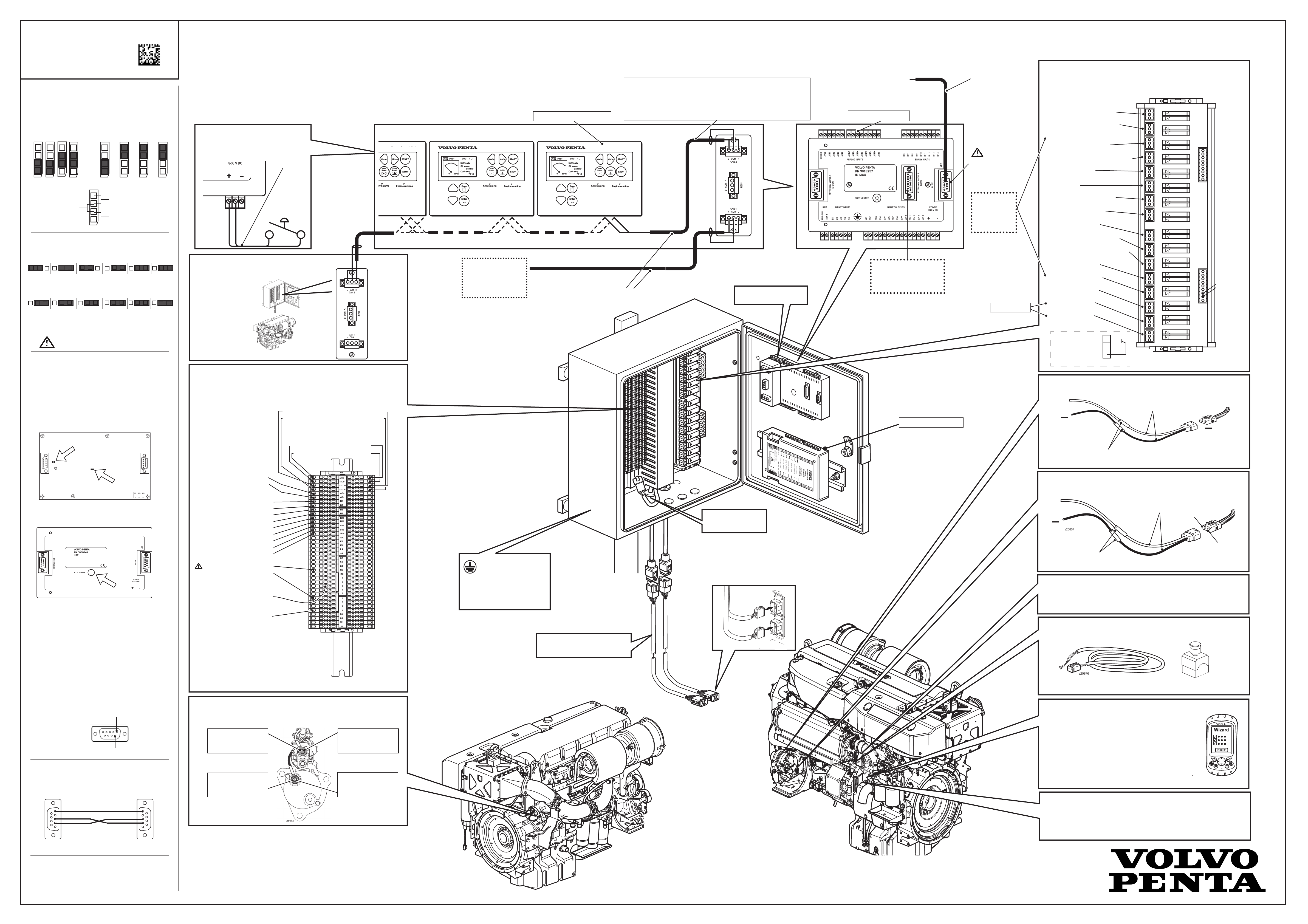
Installation Overview D9/D16 MH MCC
Propulsion
CAN2 speed 32C / 250kBd (< 200 meter between units) (default)
CAN2 speed 8C / 50kBd (< 900 meter between units) (slower response times)
MCC Electrical connection box
CAN2: Connect to optional Comap Internet Bridge
for remote monitoring via Internet/GSM
Switch for backlight
To use a switch to alternate between
adjusted brightness and 100% brightness
connect it as following:
Cables
Category A
BL
Remote Panel
Remote Panel jumper settings*
3
Remote PanelRemote Panel
Connect to PC Tool DriveCong*
Connect to external MODBUS system
Switch between PC tool and MODBUS via MCU menu.
Communication is connected here.
Standard RS232 max length 10 m.
Use a RS232 to RS485/422 converter to extend
length to 200 or 900 (set in MCU menu)
MCU jumper settings*
1
4
Cables
Category E
MODBUS connection!
Do not use 9 to 9 pin
cable. Only connect
pin 2,3, and 5.
Relay connetion (24 V Only)
Use cables Category A to all relay contact connections
Customize outputs to installation demands via tools and descriptions found on VPPN in MCC portal.
X1 Override indication
X2 Local mode indication
X3 Spare
Set in DriveCong
X4 EMS communication failure
X5 Start failure
X6 Horn
Resistance
Voltage
measurement
SDU jumper factory settings*
measurement
Current
measurement
2
AUX and combined AUX/EME is set:
ON OFF ON OFF ON OFF ON OFF ON OFF
S1 S2 S3 S4 S5* S6
ON OFF
EME is set:
ON OFF ON OFF ON OFF ON OFF ON OFF
S1 S2 S3 S4 S5* S6
Remote Panel Jumper settings*
ON OFF
Overspeed shutdown can not be switched o.
* Should be ON if used as emergency stop.
S5 External stop cannot be used if SD Override
is used as a function in the MCC system.
3
BL
1
BL
1
Loadsharing Operation (- Engine #2, #3...)
When using loadsharing connect the
COM module to the
remote panel in the
end of the chain.
The CAN2 bus is
terminated with the
COM module.
To enable load
sharing refer to:
Installation Manual
.
CAN H CAN L
5 9
Aux. I/O
equipment
CAN H CAN L
5 9
Cables
Category B
Congurable analog inputs:
1-4 and 6-8.
BL
Aux. I/O equipment
Comap RPU connection
(Redundant Protection Unit)
See the
InteliDrive User Guide
Output X3 - X13
can be congured. The stated
function is the
default setting.
Spare relay *
X7 Common shutdown
X8 Common alarm
X9 Derate alarm
X10 Ready to start engine
X11 Engine running indication
X12 Load sharing
X13 Clutch contact
X14 [internal use]
5
X15 Spare relay
X16 Spare relay
Relays X1 - X16
3. Normally Closed (NC)
2. Normally Open (NO)
X18
Pin 15,16
Connect to
0V if X15
and X16
shall be
activated.
Remove the cover to access termination jumper settings.
Remote panel CAN2 bus is terminated with120 Ohm resistor
inside the unit.
If one Remote Panel is used, leave the jumper closed (default).
If more than one Remote Panel is installed to each driveline,
the termination jumper need to have a removed (open) jumper
on all units except for the last one in the chain.
This last unit should have a closed jumper setting.
Termination jumper
CENTRAL UNIT
Boot jumper
The gure above shows the board with the cover removed.
RS 232
Power
Remote Panel Software update
BL
Remote Panel application software is uploaded automatically
from MCU during power up. Base software (rmware) do not
normally need to be downloaded. If future rmware updates
are required, the unit can be reprogrammed.
1. Power o the unit.
2. Remove the rubber plug and temporarily remove
the boot jumper.
3. Connect programming cable to RS232 and download rmware
(refer to VPPN MCC site for details)
4. Power o the unit.
5. Put back the boot jumper and the rubber plug.
Input Connections (24 V only)
Secondary battery backup
via Input connections
(to sec. battery) SEC. B+ (From engine)
(to sec. battery) SEC. B- (From engine)
Connecting the external stop
via input connection
(to external stop) STOP+ (From engine)
(to external stop) STOP- (From engine)
Use category A cable on all inputs
Lever Control 4-20 mA
A5+
A5-
Inputs external binary**
Shutdown Override B6
Aux Stop B7
Start blocking B8
Ackowledge B9
Backup Speed B10
Remote Start B11
Remote Stop B12
Spare B13
Spare B14
External Stop switch S5*
2
Connect to + at the 1
back of the remote panel.
Connect to - at the back of
the remote panel.
* Use 10 kOhms for broken wire
detection. The jumper for S5
needs to be set to enabled.
** Congurable input ports.
Ground should be applied by the shortest
cable possible with a
diameter of equal to or
greater than 2.5 mm
2
(13 AWG).
MCC to engine extension cable, 8 pin.
Total max. cable length 40 m (131 ft).
Connector A
Connector B
Diagnosis
(VODIA connection)
MCC connections
Connector B
Connector A
SDU jumper settings*
D9/D16: Secondary Battery (Backup)
+
24 V
2
16 A
Slow Fuse
Cables Category C
Secondary Battery
+
24 V
D16: Primary Battery (Air starter only)
+
24 V
16 A
Slow Fuse
Cables Category C
Pin 1
Use Crimp Tool
9512653 to crimp
From Engine
Pin 2
EasyLink connector
The connector is supporting engine mounted gauges
(not supplied with engine).
External stop switch (optional)
Only use normally open contact. Closed contact stops engine.
Remote Panel CAN2 Connection
The D-Sub (CENTRAL UNIT interface) uses the following pins:
CAN H - 5
CAN L - 9
Cable for DriveCong/DriveMonitor*
The Connector used for PC Tool (DriveCong/DriveMonitor )has
the following wiring:
5
3
2
4
5
3
2
PC MCU
Electrical and combined Electrical /Air starter
D16:
Connect + battery cable here.
D16:
Connect - battery cable here.
Bolt size M12. Tightening
torque 25 ± 5 Nm
D9:
Connect + battery cable here.
Bolt size M10. Tightening
torque 18 ± 2 Nm
D9:
Connect - battery cable here.
Bolt size M10. Tightening
torque 24 ± 2 Nm
Diagnose VODIA connection
Used for installation set-up and service. Commonly changed
parameters:
ISD Change EMS low voltage when running (18-25,5V)
25,5V default.
BPN Amount of droop (0,1% to 4,98%) 4% default.
Note! VODIA has software download support for EMS only.
Connector A and B (MCC connections)
Connector A: Engine interface to control and monitoring system.
CAN/J1939 communication bus.
Connector B: Shutdown system interface.
Spare Relay*
Relays marked with “Spare Relay” are allowed to use as desired.
Activate by 0V. Note that it may require special settings to make
them operational.
5
Page 2
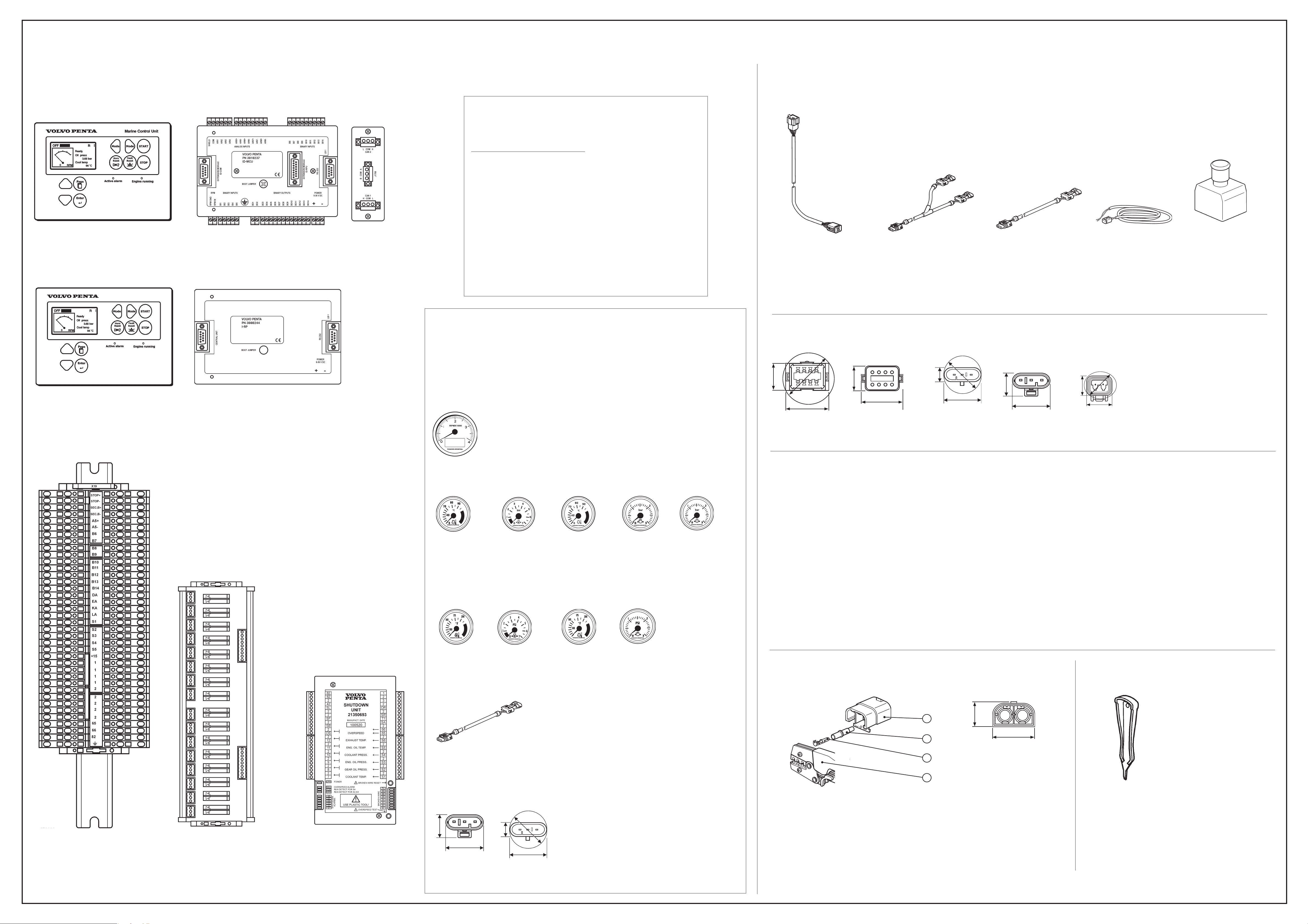
Components and Cables
Components
Cables
MCU / Remote Panel Engine Data
PRP
MCU Marine Control Unit
Part no.
3818237
Front View
Remote Panel
BL
Rear View
ID-COM
Part no.
3818364
Indicator Propulsion
Engine Speed X
Load X
Fuel Rate X
Actual Torque X
Demand Torque X
Throttle pos X
Oil Press X
Oil Temp X
Coolant Press X
Coolant Temp X
SeaWaterPres* X
Exhaust Temp X
ChrgAirPress X
ChrgAirTemp X
Fuel Press X
CrankcasPres X
*Depends on cooling system.
MCC to engine extension cable, 8-pin
Feet Meter Part no.
9.8 3 874414
16.4 5 874119
22.9 7 874386
29.5 9 874387
36.1 11 874388
Water in fuel Y-Split cable harness, 3-pin
Part no. 21495971
Water in fuel cable harness,
3-pin
Feet Meter Part no.
9.8 3 21415866
16.4 5 21415883
External stop switch cable,
2-pin
Feet Meter Part no.
32.8 10 3840677
External Stop Switch
Part no.
3589458
NO/NC contacts
Cable not included. Use External
Stop Switch Cable Part no. 3840677
Remote Panel
Part no.
3888244
PRP
Front View
BL
Rear View
Optional Engine Instruments (Easy Link)
Box
Part no. 3837995
Tachometer (rpm, h)
Engine speed and hours
Instruments
Use with Attachment ring: Part no. 874450. Hole diam. 52 mm (2.04”)
For installation of tachometer and max. three other instruments, see below.
H = 222 mm (8.74”)
W= 146 mm (5.78”)
D = 100 mm (3.93”)
Part Part no.
Tachometer 874903
Attachment ring 874449 Hole 85 mm (3.35”)
Front ring 874447
Connector dimensions
D
H
W
8-pin male
H = 20 mm (0.78”)
W = 37 mm (1.45”)
D = 43 mm (1.69”)
Category A
Crosscut area minimum 1,5 mm2 (16 AWG) type approved low voltage (30 V or more) ship cable, Max 50 meters (164 ft)
H
W
8-pin female
H = 20 mm (0.78”)
W = 37 mm (1.45”)
Terminal block / relay connections
H
3-pin male
H = 18 mm (0.71”)
W = 26 mm (1.02”)
D = 26 mm (1.02”)
D
H
W
W
3-pin female
H = 20 mm (0.79”)
W = 25 mm (0.98”)
D
H
W
2-pin plug
H = 11 mm (0.43”)
W = 16 mm (0.63”)
D = 18 mm (0.71”)
Oil temp (C°)
Color Part no.
Black 874905
White 874922
Oil pressure (Bar)
Color Part no.
Black 874908
White 874923
Coolant temp (C°)
Color Part no.
Black 874904
White 874921
Instruments US setup
Use with Attachment ring: Part no. 874450. Hole diam. 52 mm (2.04”)
Oil temp (F°)
Color Part no.
Black 881857
White 881858
Oil pressure (psi)
Color Part no.
Black 874919
White 874932
Coolant temp (F°)
Color Part no.
Black 874918
White 874931
Turbo pressure (Bar)
Color Part no.
Black 874910
White 874924
Turbo pressure (psi)
Color Part no.
Black 874920
White 874933
Coolant pressure (Bar)
Color Part no.
Black 874911
Category B
Crosscut area min. 0,25 mm2 (23 AWG) 120 Ohm nominal impedance, Maximal attenuation (at 1 MHz) 2 dB / 100 m (328 ft), Max 900 meters (2953 ft) Nominal Velocity of Propagation min. 75% (max. 4,4 ns/m)
Category C
Crosscut area 2,5 mm2 (13 AWG) type approved low voltage (30 V or more) ship cable, Max 30 meters (98 ft)
Category D
Refer to Installation manual D5-D16 Publ. no: 47704151 for dimensions.
Category E
RS232: Use signal cable with 2-3, 3-2, 5-5 cable (max. 10 meter / 32.8 ft). Note! MODBUS failures will occur if 9 to 9 pin cable is used.
RS485/422: Less than 40 meters (131 ft): Crosscut min. 0,75 mm2, (18 AWG) 120 Ohm impedance, Max. attenuation (at 1 MHz) 1,7 dB / 100 m (328 ft)
RS485/422: Longer than 40 meters (131 ft): Drain wired, crosscut min. 0,75 mm2 (18 AWG) 120 Ohm impedance, Max. attenuation (at 1 MHz) 1,7 dB / 100 m (328 ft)
Secondary Battery (backup) Connection (D9/D16) and
CAN communication. Shielded, pairtwisted
Secondary Battery
Battery cables
RS232 / MODBUS. Shielded, pairtwisted
Input Connection Tool
Primary battery Connection (D16 only)
Input Connection
Part no.
21350704
Relay Connection
Part no.
3818362
SDU - Shutdown Unit
Part no.
21350693
Spare part no.
(includes reference to calibration document)
3819845
Cables
EasyLink ,
3-pin
Feet Meter Part no.
3.3 1 874759
9.8 3 3807043
Connector dimensions
D
H
W
3-pin female
H = 20 mm (0.79”)
W = 25 mm (0.98”)
H
W
3-pin male
H = 18 mm (0.71”)
W = 26 mm (1.02”)
D = 26 mm (1.02”)
1
2
3
4
Crimping parts
Part Part no.
1. Housing* 1307049
2. Isolator* 1608765
3. Pin* 969832 (2,5 mm2 /13 AWG) Max. insulation diam. 3,1 mm (included in engine harness)
Pin 948291 (2,5 mm2 /13 AWG) Max. insulation diam. 4,5 mm (not included)
4. Crimping tool 951 2653
* Included in engine delivery.
Note!
Remove the blind plugs before crimping.
H
W
2-pin
H = 15 mm (0.59”)
W = 24 mm (0.94”)
Tool
Part
Tool Included in Steel box MCC
47705609 03-2014
 Loading...