

Page 1

OPERATOR’S MANUAL
D1, D2
Page 2

CALIFORNIA PROPOSITION 65 WARNING
Engine exhaust, some of its constituents, and a broad range of engine parts are known to the State of California to cause cancer, birth
defects, and other reproductive harm. Additionally, lubricants, fuels, and other uids used in engines–including any waste created through
the wearing of engine parts–contain or produce chemicals known to the State of California to cause cancer and birth defects or other
reproductive harm.
Battery posts, terminals, and related accessories contain lead and lead compounds. Wash your hands after handling. Used engine oil
contains chemicals that have caused cancer in laboratory animals. Always protect your skin by washing thoroughly with soap and water.
47702088 - Downloaded from www.volvopenta.com 02/06/2011 18:54:55
Page 3

Content
Foreword ...................................................................................................... 2
Safety Information ...................................................................................... 3
Introduction ................................................................................................. 8
Instruments and Controls ........................................................................ 10
Starting ...................................................................................................... 18
Operation ................................................................................................... 20
Engine Shutdown ...................................................................................... 23
Fault Handling ........................................................................................... 25
In Case of Emergency .............................................................................. 29
Maintenance Schedule ............................................................................. 31
Maintenance .............................................................................................. 33
Storage ....................................................................................................... 64
Technical Data ........................................................................................... 68
Operator's Manual Order .......................................................................... 74
Alphabetical index .................................................................................... 75
47702088 - Downloaded from www.volvopenta.com 02/06/2011 18:54:55
1
Page 4

Foreword
Volvo Penta marine engines are used all over the world. They are used in all possible operating conditions for
professional as well as leisure purposes. This is not a coincidence. After 100 years as an engine manufacturer
the Volvo Penta name has become a symbol of reliability, technical innovation, top of the range performance and
long service life. We also believe that this is what you demand and expect of your Volvo Penta engine.
We would like you to read this operator’s manual thoroughly and consider the advice we give on running and
maintenance before your maiden voyage so that you will be ensured of fulfilling your expectations. Please pay
attention to the safety instructions contained in the manual.
As owner of a Volvo Penta marine engine, we would also like to welcome you to a worldwide network of dealers
and service workshops to assist you with technical advice, service requirements and replacement parts. Please
contact your nearest authorized Volvo Penta dealer for assistance.
You will find your closest dealer at our home page on the Internet www.volvopenta.com - amongst other
useful information about your Volvo Penta engine - we invite you to visit!
47702088 - Downloaded from www.volvopenta.com 02/06/2011 18:54:55
2 47702088 05-2011
Page 5
Safety Information
!
Read this chapter very carefully. It has to do with your safety. This describes how safety information is presented
in the operator’s manual and on the product. It also gives you an introduction to the basic safety rules for using
and looking after the engine.
Check that you heave received the correct operator’s manual before you read on. If not, please contact
your Volvo Penta dealer.
This symbol is used in the operator’s manual and on the product, to call your attention
to the fact that this is safety information. Always read such information very carefully.
Safety texts in the operator’s manual have the following order of priority:
DANGER!
Indicates a hazardous situation which, if not avoided, will result in death or serious
injury.
WARNING!
Indicates a hazardous situation which, if not avoided, could result in death or serious
personal injury.
CAUTION!
Indicates a hazardous situation which, if not avoided, could result in minor or moderate
personal injury.
IMPORTANT!
Indicates a situation which, if not avoided, could result in property damage.
47702088 - Downloaded from www.volvopenta.com 02/06/2011 18:54:55
NOTICE! Used to draw attention to important information that will facilitate work or
operations.
This symbol is used on our products in some cases and refers to important information
in the operator’s manual. Make sure that warning and information symbols on the
engine are clearly visible and legible. Replace symbols which have been damaged or
painted over.
47702088 05-2011 3
Page 6

Safety Information
Your new boat
Read the instruction books and other information
carefully, which came with your new boat. Learn to
handle the engine, controls and other equipment in a
safe and correct manner.
If this is your first boat, or a type of boat you are not
experienced in using, we recommend that you practice operating the boat in peace and quiet. Get to know
the way the boat reacts to sea and to the controls
under different speed, sea and loading conditions
before you cast off for your first “real” maiden voyage.
Remember that the captain of every boat is required
by law to know and to observe applicable rules for
traffic and safety at sea. Get to know the rules which
apply to you and your waters, by contacting the relevant authority or sea safety organization.
It is a good idea to go on some kind of boat operation
course. We recommend that you contact a regional
boat or sea safety organization to find a suitable
course.
Daily checks
Make it a habit to give the engine and engine bay a
visual check before driving (before starting the
engine) and after operation (when you have stopped
the engine). This helps you to quickly discover
whether any leakage of fuel, coolant, oil or any other
abnormal event has happened, or is about to happen.
Fuel filling
There is always a risk of fire and explosion during fuel
filling. Smoking is not permissible, and the engine
should be stopped.
Never over-fill the tank. Shut the tank cap securely.
Only use the fuel recommended in the instruction
book. The wrong grade of fuel can cause serious malfunctions, power loss or stop the engine.
Do not start the engine
Do not start the engine if you suspect a fuel or LPG
leak in the boat, close to explosive media, or if there
is a spillage of explosive media. An explosive environment entails a risk of fire and/or explosion.
Manoeuvring
Avoid sudden or surprising rudder movements and
gear shifting. There is a risk that passengers could fall
over, or overboard.
A rotating propeller can cause severe injury. Check
that there is nobody in the water before you engage
forward / astern (reverse) drive. Never drive close to
47702088 - Downloaded from www.volvopenta.com 02/06/2011 18:54:55
bathers or in areas where you could reasonably
expect that people could be in the water.
Accidents and near misses
Life saving statistics show that inadequate care of
boats and engines, and deficiencies in safety equipment are frequent causes of accidents and near
misses at sea.
Make sure that your boat and engine are maintained
in accordance with the advice in each instruction
book, and that the necessary safety equipment is on
board, and is in working condition.
4 47702088 05-2011
Page 7
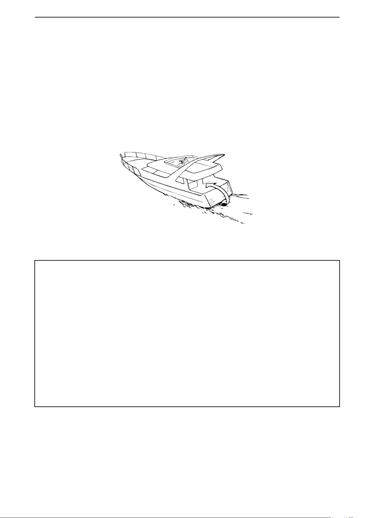
Carbon monoxide poisoning
P0003073
When a boat moves forwards, an area of low pressure
air forms behind the boat. In adverse conditions, this
low pressure can be so strong that the boat’s own
exhaust fumes are sucked into the cockpit or cabin,
which entails a risk of carbon monoxide poisoning for
all aboard.
The problem of low-pressure suction is worst in high,
wide boats with a square transom. But even in other
types of boats, low-pressure suction can be a problem
in some conditions, such as if you drive with the hood
up. Other factors which increase the low-pressure
effect are wind conditions, load distribution, pitching,
trimming, open windows and ventilators etc.
Safety Information
Most modern boats are designed so that the problem
of low-pressure suction is very rare, however. If lowpressure suction does occur anyway, do not open
hatches or ventilators in the forward part of the boat.
Strangely enough, this makes the problem worse. Try
changing speed, trimming or load distribution instead.
Also try taking down/opening the hood or modifying it
in some other manner. Ask your boat dealer for advice
about the best solution for your particular boat.
Remember
• Safety equipment: Life jackets for everybody aboard, communication equipment, emergency
rockets, approved fire extinguisher, first aid kit, life buoy, anchor, paddle, torches etc.
• Spare parts and tools: Impeller, fuel filters, fuses, tape, hose clamps, engine oil, propeller and
tools for the jobs you could be expected to have to do.
47702088 - Downloaded from www.volvopenta.com 02/06/2011 18:54:55
• Take your chart out and study your planned route. Calculate distance and fuel consumption.
Listen to weather reports.
• Tell your friends/relatives about route plans if you undertake a long journey. Remember to
notify changed plans or delays.
• Inform everybody aboard about where the safety equipment is located, and how it works. Make
sure that there is more than one person aboard who can start and operate the boat safely.
This list can be extended, since the need for safety equipment varies with the type of boat, and
where or how it is used etc. We recommend that you ask a regional boat or sea safety organization
for more detailed maritime safety information.
47702088 05-2011 5
Page 8

Safety Information
Preparations
Knowledge
The operator’s manual contains instructions on how
to carry out general maintenance and service operations safely and correctly. Read the instructions carefully before starting work.
Service literature covering more complicated operations is available from your Volvo Penta dealer.
Never carry out any work on the engine if you are
unsure of how it should be done, contact your Volvo
Penta dealer who will be glad to offer assistance.
Stop the engine
Stop the engine before opening or removing engine
hatches. Unless otherwise specified all maintenance
and service must be carried out with the engine stopped.
To prevent accidental start of the boat engine, remove
the ignition key, turn off the power supply to the engine
at the main switches and lock them in the OFF position before starting work. Put up a warning sign in the
control position that work on the engine is being carried out.
Approaching or working on an engine which is running
is a safety risk. Loose clothing, hair, fingers or a dropped tool can be caught in the rotating parts of the
engine and cause serious personal injury. Volvo
Penta recommend that all servicing with the engine
running should be undertaken by an authorized Volvo
Penta workshop.
Lifting the engine
When lifting the engine, use the lifting eyes installed
on the engine (reverse gear where installed). Always
47702088 - Downloaded from www.volvopenta.com 02/06/2011 18:54:55
check that lifting equipment is in good condition and
has sufficient load capacity to lift the engine (engine
weight including reverse gear and any extra equipment installed). For safety’s sake lift the engine using
an adjustable lifting beam. All chains and cables
should run parallel to each other and as perpendicular
as possible in relation to the top of the engine. Bear
in mind that extra equipment installed on the engine
may alter its center of gravity. Special lifting equipment may then be required in order to maintain the
correct balance and make the engine safe to handle.
Never carry out work on an engine suspended on a
hoist.
Before starting the engine
Reinstall all protective parts removed during service
operations before starting the engine. Check that no
tools or other items have been left on the engine.
Never start a turbocharged engine without installing
the air cleaner (ACL). The rotating compressor in the
Turbocharger unit can cause serious personal injury.
Foreign objects can also be sucked in and cause
mechanical damage to the unit.
Fire and explosion
Fuel and lubrication oil
All fuel, most lubricants and many chemicals are
inflammable. Read and follow the instructions on the
packaging.
When carrying out work on the fuel system, make sure
the engine is cold. A fuel spill onto a hot surface or
electrical components can cause a fire.
Store fuel soaked rags and other flammable material
so that there is no danger of them catching fire. Fuelsoaked rags can self-ignite under certain conditions.
Do not smoke when filling fuel, oil or in proximity of a
filling station or in the engine room.
Non-original components
Components used in the fuel and electrical systems
on Volvo Penta products are designed and constructed to minimize the risk of fire and explosion.
Using spare parts other than by Volvo Penta
approved spare parts can result in fire or explosion on
board.
Batteries
The batteries contain and emit oxyhydrogen gas,
especially during charging. This gas is easily ignited
and highly volatile.
Do not under any circumstances smoke or use naked
flame or allow sparks in the vicinity of the batteries or
battery compartment.
An incorrect connection of a battery terminal cable or
jump-start cable can cause a spark which in its turn
can be sufficient to cause an explosion.
Start spray
Never use start spray or similar agents to start an
engine equipped with air pre-heating (glow plugs/
starter element). This may cause an explosion in the
inlet manifold. Danger of personal injury.
6 47702088 05-2011
Page 9

Safety Information
Hot surfaces and fluids
There is always a risk of burns when working with a
hot engine. Beware of hot surfaces. For example: the
exhaust pipe, turbo unit, oil pan, charge air pipe,
starter element, hot coolant and hot oil in oil lines and
hoses.
Carbon monoxide poisoning
Only start the engine in a well-ventilated area. If operating the engine in an enclosed space, ensure that
there is proper ventilation in order to remove exhaust
gases and crankcase ventilation emissions from the
working area.
Chemicals
Most chemicals such as anti-freeze, rustproofing
agent, inhibiting oil, degreasing agent etc. are hazardous to health. Read and follow the instructions on
the packaging.
Some chemicals such as inhibiting oil are inflammable
and dangerous if breathed in as well. Ensure good
ventilation and use a protective mask when spraying.
Read and follow the instructions on the packaging.
Store chemicals and other hazardous materials out of
the reach of children. To protect the environment,
please dispose of used or leftover chemicals at a
properly designated disposal site for destruction.
Cooling system
There is a risk of flooding when working on the seawater system. Turn off the engine and close the sea
cock (where installed) before starting work on the system.
47702088 - Downloaded from www.volvopenta.com 02/06/2011 18:54:55
Avoid opening the coolant filler cap when the engine
is hot. Steam or hot coolant can spray out and cause
burns.
Fuel system
Always use protective gloves when tracing leaks. Liquids ejected under pressure can penetrate body tissue and cause serious injury. There is a danger of
blood poisoning.
Always cover the generator if it is located under the
fuel filter. The generator can be damaged by spilled
fuel.
Electronic Vessel Control (EVC)
The boat has a advanced control system. Never cut
or modify connectors, wiring or splice of the components.
Installing non Volvo Penta components may cause
the system to malfunction.
Service must be done by approved workshops.
Electrical system
Cutting off power
Always stop the engine and break the current using
the main switches before working on the electrical
system. Isolate shore current to the engine block
heater, battery charger, or accessories mounted on
the engine.
Batteries
The batteries contain an extremely corrosive electrolyte. Protect your skin and clothes when charging or
handling batteries. Always use protective goggles and
gloves.
If battery electrolyte comes into contact with unprotected skin, wash off immediately using plenty of
water and soap. If battery acid comes into contact with
the eyes, flush immediately with plenty of water and
obtain medical assistance without delay.
If work must be carried out with the engine at operating temperature and the coolant filler cap or a cock
open or a coolant hose disconnected, open the coolant filler cap carefully and slowly to release pressure
before removing the cap completely. Note that the
coolant may still be hot and can cause burns.
Lubrication system
Hot oil can cause burns. Avoid skin contact with hot
oil. Ensure that the lubrication system is not under
pressure before commencing work on it. Never start
or operate the engine with the oil filler cap removed,
oil can spray out.
47702088 05-2011 7
Page 10

Introduction
This Operator's Manual has been prepared to give you the greatest possible benefit from your Volvo Penta marine
engine. It contains the information you need to be able to operate and maintain the engine safely and correctly.
Please read the Operator's Manual carefully and learn to handle the engine, controls and other equipment in a
safe manner before you cast off on your maiden voyage.
Always have the Operator's Manual available. Store it safely and do not forget to hand it over to the next owner
if you sell your boat.
The Operator’s Manual describes the engine and equipment sold by Volvo Penta. The illustrations in this book
covers several varieties and might differ, the essential information is always correct though. Installations with e.g.
different controls and instrumentation might occur, in these cases we refer to this products manual.
Warranty
Your new Volvo Penta marine engine is covered by a
limited warranty, under the conditions compiled in the
Warranty book.
Please note that AB Volvo Penta’s liability is limited to
the specification in the Warranty book. Read it carefully, as soon as possible after delivery. It includes
important information about warranty cards, service,
maintenance, which it is the responsibility of the
owner to know, check and carry out. If this is not done,
AB Volvo Penta may fully or partly refuse to honour its
warranty undertakings.
Please contact your Volvo Penta dealer if you
have not received a Warrant book, a Service book
or a customer copy of the warranty card.
Environmental care
All of us want to live in a clean, healthy environment.
Where we can breathe clean air, see healthy trees,
have clean water in lakes and seas, and be able to
enjoy the sunlight without fearing for our health.
Unfortunately, this is not self-evident these days, it is
47702088 - Downloaded from www.volvopenta.com 02/06/2011 18:54:55
something all of us must work hard for.
As a manufacturer of marine engines, Volvo Penta
has particular responsibility and for this reason, environmental care is a core value in our product development. Volvo Penta has a wide engine programme
these days, where considerable progress has been
made in reducing exhaust fumes, fuel consumption,
engine noise etc.
We hope that you will be want to preserve these values. Always observe the advice in the Operator's
Manual about fuel grades, operation and maintenance, to avoid unnecessary environmental impact.
Please contact your Volvo Penta dealer if you notice
any changes such as increased fuel consumption or
increased exhaust smoke.
Moderate your speed and distance so that wake and
noise do not disturb or damage animal life, moored
boats, jetties etc. Leave the archipelago and harbours
in the same state you would like to find them. Remember to always hand in drained oil, coolant, paint and
wash residue, used batteries etc. for destruction at a
recycling station.
If we all pull together, we can make a valuable contribution to the environment together.
Running in
The engine must be “run in” during its first 10 hours,
as follows:
Use the engine in normal operation. Full load should
only be applied for short periods. Never run the engine
for a long period of time at constant speed during this
period.
Higher oil consumption is normal during the running
in period. For this reason, check the oil level more
frequently than normally recommended.
After the first period of operation, the specified warranty inspection “First service inspection” can be
done. For more information: Please refer to the Maintenance Schedule.
Fuel, oils and coolant
Only use the fuels and oils recommended in the Operator's Manual. Other grades can cause malfunctions,
increased fuel consumption and eventually even
shorten the life of the engine.
Always change the oil, oil filters and fuel filter at the
specified intervals.
Future warranty claims related to engine and accessories may be refused if an unsuitable coolant has
been used, or if the instructions for coolant mixture
have not been followed.
8 47702088 05-2011
Page 11

Introduction
Service and spare parts
Volvo Penta marine engines are designed for high
reliability and long life. They are built to withstand a
marine environment, but also to have the smallest
possible environmental impact. Through regular service and use of by Volvo Penta approved spare parts,
these qualities are retained.
Volvo Penta’s world-wide network of authorised dealers is at your service. They are Volvo Penta product
specialists, and have the accessories, original spares,
test equipment and special tools needed for high quality service and repair work.
Always observe the maintenance intervals in the
Operator's manual, and remember to note the engine/
transmission identification number when you order
service and spare parts.
Certified engines
If you own or operate an emission certified engine it
is important to be aware of the following:
Certification means that an engine type has been
checked and approved by the relevant authority. The
engine manufacturer guarantees that all engines
made of the same type are equivalent to the certified
engine.
This makes special demands on the care and
maintenance you give your engine, as follows:
• Maintenance and service intervals recommended by Volvo Penta must be complied with.
• Only Volvo Penta original spares may be used.
• Service on injection pumps, pump settings and
injectors must always be done by an authorised
Volvo Penta workshop.
• The engine must not be converted or modified,
except for the accessories and service kits
which Volvo Penta has approved for the engine.
• Installation changes to the exhaust pipe and
engine air inlet ducts must not be done.
47702088 - Downloaded from www.volvopenta.com 02/06/2011 18:54:55
• No seals may be broken by unauthorised personnel.
The general advice in the Operator's manual about
operation, care and maintenance apply.
Late or inadequate maintenance/service or the use of
spare parts not approved by Volvo Penta will invalidate AB Volvo Penta’s responsibility for the engine
specification being in accordance with the certificated
variant.
Volvo Penta accepts no responsibility or liability for
any damage or costs arising due to the above.
47702088 05-2011 9
Page 12

Instruments and Controls
1
2
3
4
This chapter describes the instruments, panels and controls Volvo Penta sells for your engine.
If you would like to complement your instrumentation, or if your boat is equipped with instruments not described
here, we ask that you contact your Volvo Penta dealer.
Ignition Lock
The system lacks a start lock. Therefore, the helm station should be lockable, or alternatively a lockable main
switch should be fitted, to prevent unauthorized engine
start.
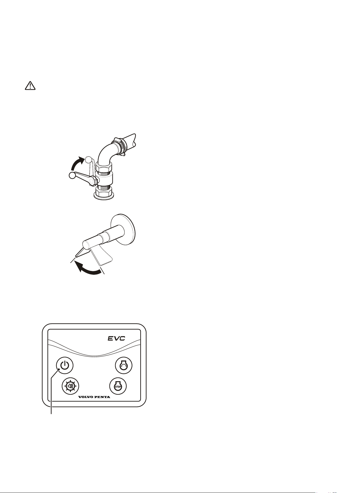
Start/Stop Panel
Control Panel
On/Off button (1)
Depress the button to start or stop the system.
The panel cannot be switched off when the engine is
running.
47702088 - Downloaded from www.volvopenta.com 02/06/2011 18:54:55
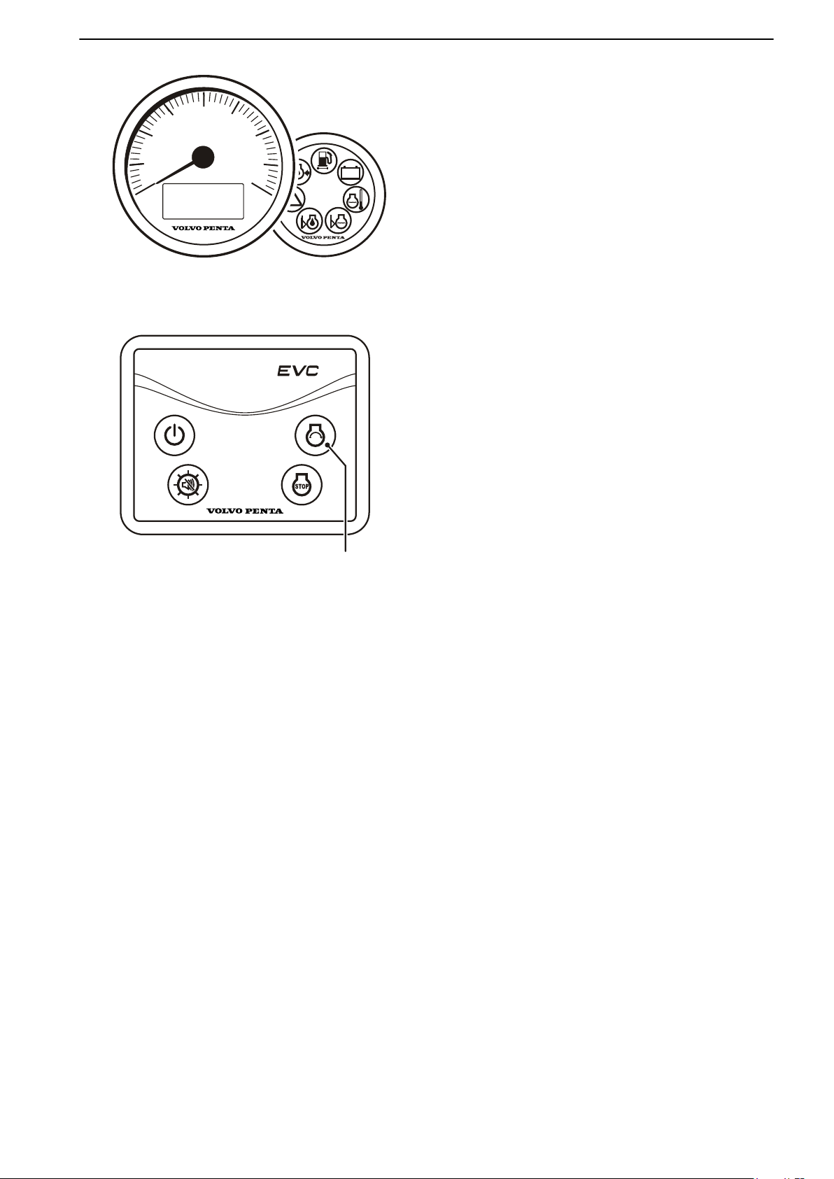
Start button (4)
When the button is depressed the pre-heat function is
activated and the start motor engaged.
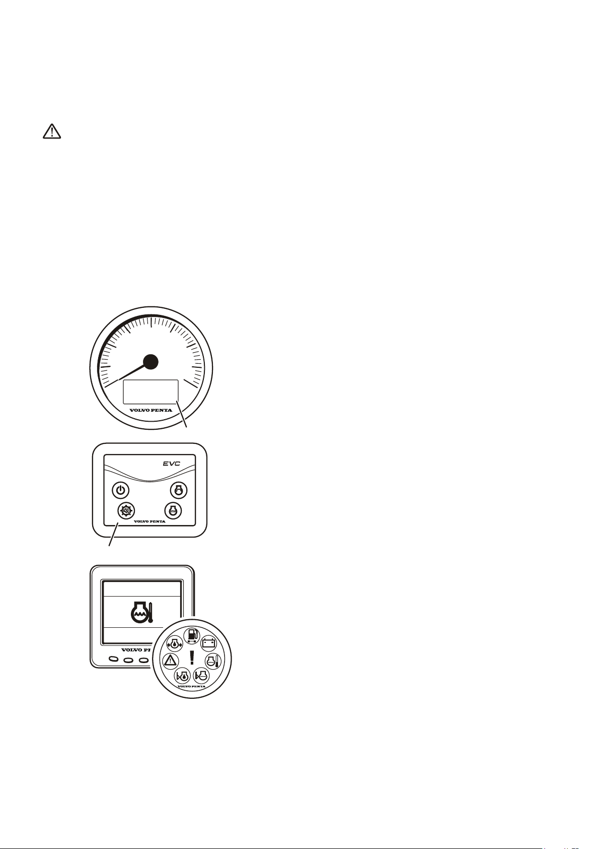
Multi-function button (2)
Confirm the alarm. If an alarm occurs, a flashing
•
warning symbol will be displayed in the tachometer
window and an audible alarm will sound.
The alarm is confirmed by depressing the multifunction button. The audible alarm is silenced and
the warning symbol is lit continuously until the fault
is remedied.
Backlighting. To switch tachometer window back-
•
lighting on or off, depress the button for 1 - 5 seconds.
The backlighting can be adjusted in five steps by
depressing the button for less than 1 second.
Adjust the tachometer window contrast by holding
•
down the button for more than 5 seconds.
Stop button (3)
The engine stops running when the button is
depressed.
10 47702088 05-2011
Page 13
AUX
1
2
3
4
5
6
7
8
9
0
3
2
1
4
RPMX1000
P0007517
Instruments and Controls
Gauges
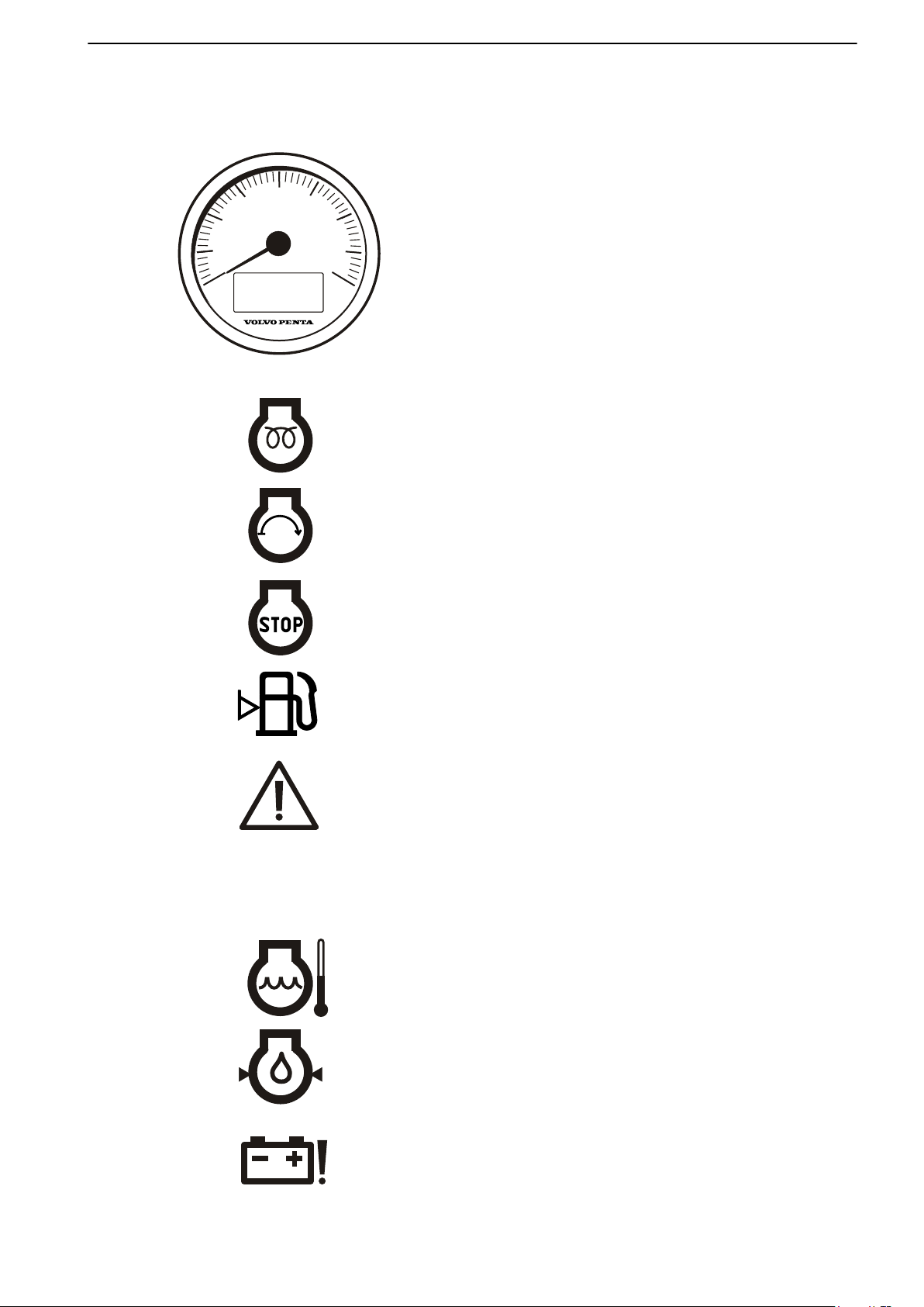
Tachometer
The tachometer shows engine speed; multiply the
value shown on the dial by 1,000 to get the number of
engine revolutions per minute.
Operating information is displayed in the tachometer
window.
47702088 - Downloaded from www.volvopenta.com 02/06/2011 18:54:55
Operating information symbols
1 Pre-heating
The pre-heat symbol is displayed when the glow
function is active.
2 Starting
The start symbol is displayed when the start motor
is engaged.
3 Stopping
The stop symbol is shown when the stop button is
depressed.
4 Fuel level
If a fuel level sensor is installed (accessory) the fuel
level symbol is displayed when there is around 20%
of fuel remaining in the tank.
The engine must run for at least one minute before
the function is activated.
5 System fault
The system fault symbol lights up in the case of
short circuits or cable breaks.
6 Auxiliary alarm
Auxiliary alarm for accessory sensors.
7 Coolant temperature
The coolant temperature symbol lights up if the
engine coolant temperature is too high.
8 Oil pressure
If the oil pressure lamp lights up during operations,
the engine oil pressure is too low.
9 Charging
The charging lamp lights up if the alternator stops
charging.
47702088 05-2011 11
Page 14
1
P0007518
Instruments and Controls
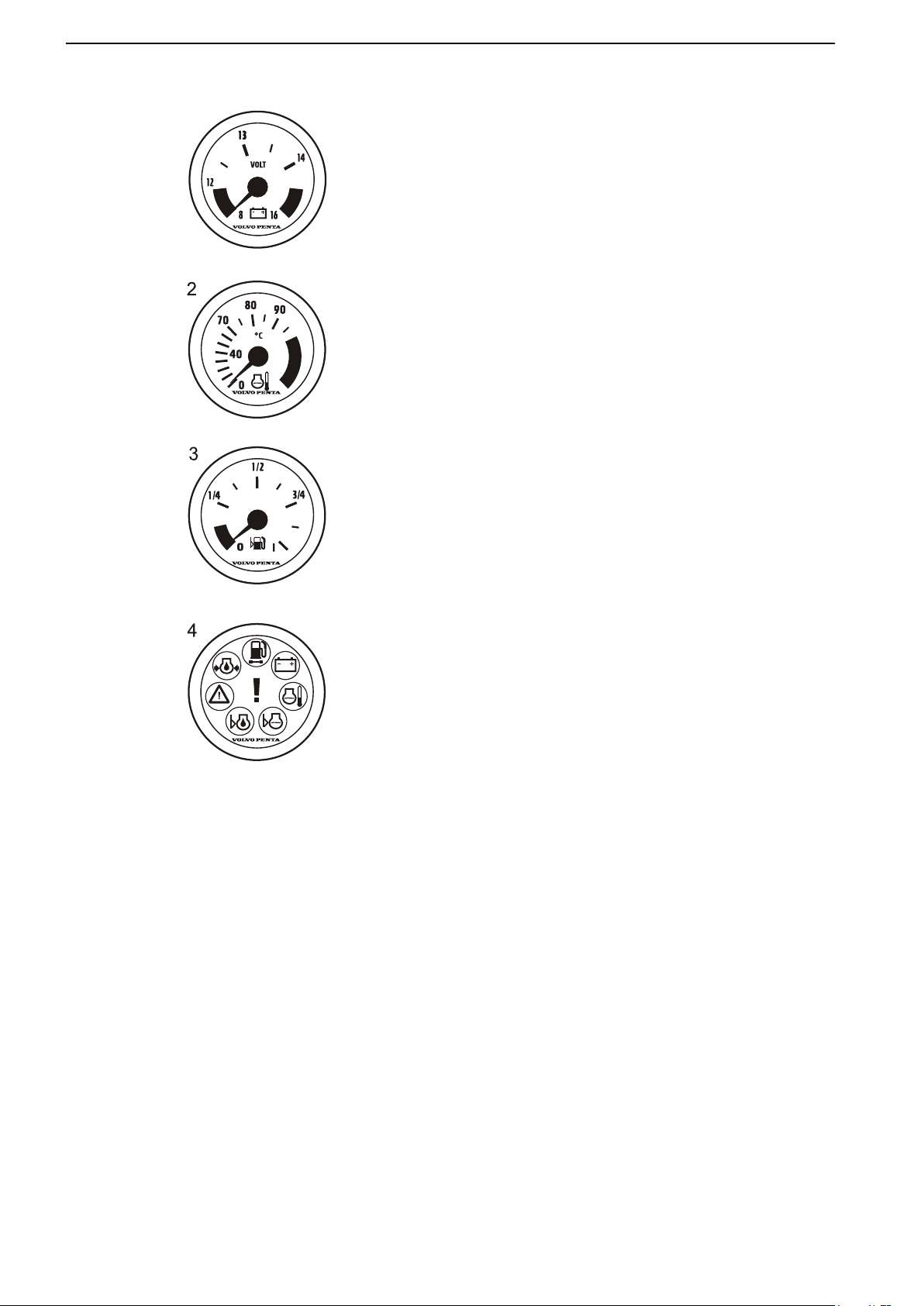
Optional instruments
These instruments are sold as engine accessories by
Volvo Penta.
1 Voltmeter, battery charging
The meter shows the alternator charge current.
During operations the charge voltage must be
around 14 V. When the engine is stopped and electrical power switched on, battery voltage is around
12 V.
2 Coolant temperature gauge
The instrument shows engine coolant temperature.
During operations coolant temperature must normally be between 75-95°C (167-203°F).
3 Fuel level gauge
The fuel level gauge shows the quantity of remaining fuel.
4 Alarm monitor
The alarm monitor gives a visual warning to call
attention to any alarms that occur.
47702088 - Downloaded from www.volvopenta.com 02/06/2011 18:54:55
12 47702088 05-2011
Page 15
1 2
3
4 5
G H
P0001168
0
ENGINE HOURS
HOURS
P0003010
Instruments and Controls
EVC System Display
It is possible to present several windows with different
operational information in the EVC system display. The
various screens are selected using the instrument buttons.
Before the display is put to use certain settings must
be entered in the configuration menu; refer to Config-
uration menu.
It is also possible to bring up a menu identical to that
shown in the tachometer display by navigating to System information in the Configuration menu, or by
depressing button 2; refer to Multi, button 2.
47702088 - Downloaded from www.volvopenta.com 02/06/2011 18:54:55
A self-test is performed at start; the display will emit a
constant audible signal if a fault is detected. The display will continue to function, but may behave in unexpected ways.
Only installed functions are shown in the display.
Screens
Depress any of the buttons 1 to 4 to bring up the function menu for the buttons on the lower part of the display.
Buttons 1, 2 and 4 provide different screens.
Button 1 – Engine
Button 2 – Multi
Button 4 – Graph
Use button 5 to adjust contrast and to access the configuration menu for display settings; refer to Configu-
ration menu.
Exit the menu by waiting a few seconds or by depressing button 5 (EXIT).
Contrast
The display has five contrast settings. Depress button
5 (far right) and change the contrast by depressing +
(button 4) or – (button 3).
Store the setting by depressing EXIT (button 5).
47702088 05-2011 13
Page 16
P0007392
P0003011
Instruments and Controls
Engine, button 1
Engine revolutions and speed are shown in the upper
part of the window. Operating hours are displayed in
the lower part, along with a fuel level indicator if this
function is installed.
If speed information is lacking, coolant temperature will
be shown instead.
Multi, button 2
Operational information is displayed in four analog or
digital windows in the multi screen. The display can
either show several windows, or be divided so that the
lower part shows System information. To switch
between the different screens depress button 2 repeatedly.
47702088 - Downloaded from www.volvopenta.com 02/06/2011 18:54:55
If the selected information is lacking, the symbol “—”
will be displayed: for analog instruments the dial will be
absent.
Selecting screens
Depress the right arrow (button 5) to select the information to be displayed in each respective window.
Then repeatedly depress the button that corresponds
to the window to be set until the desired information is
shown.
The type of information accessible depends on the
type of electrical system and sensors the boat is equipped with.
14 47702088 05-2011
Page 17
4000
2000
P0002420
Instruments and Controls
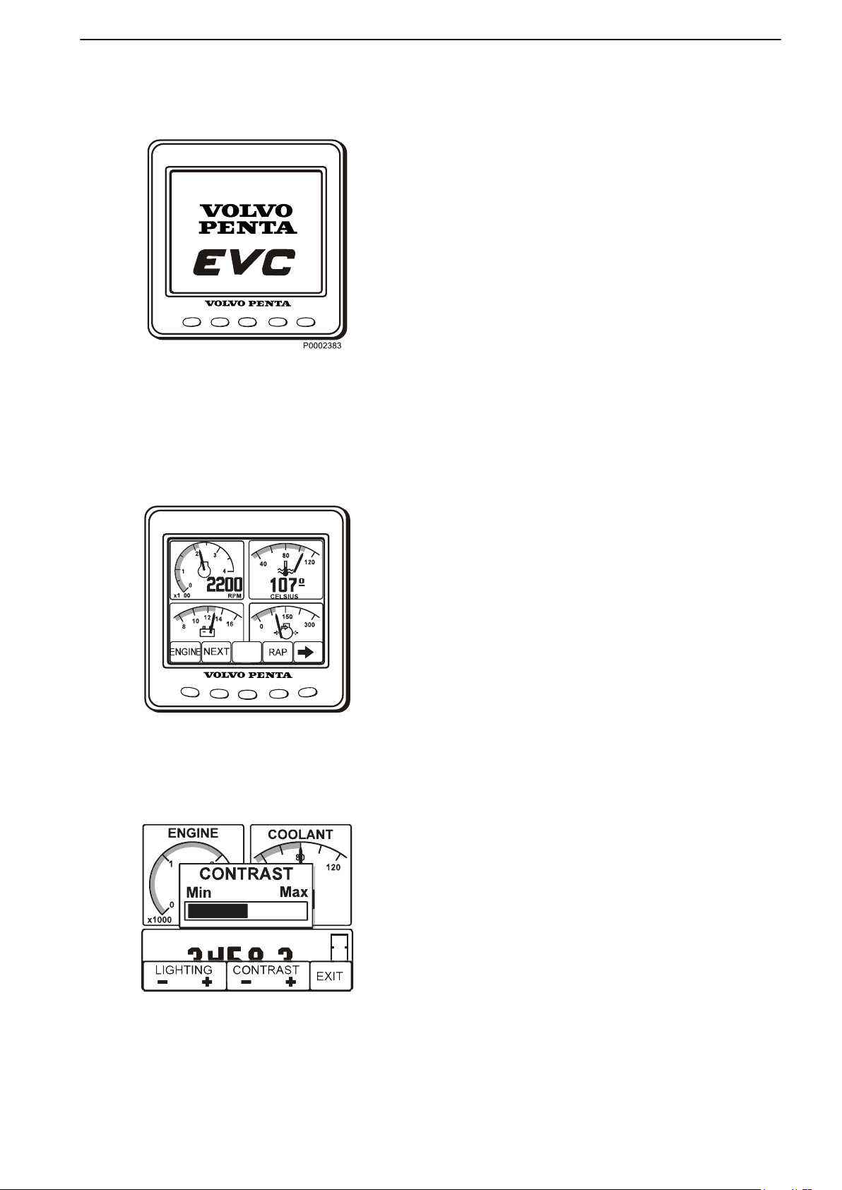
Graph, button 4
This screen displays operational information in the
form of graphs. Depress button 4 repeatedly to select
the information to be displayed. To set the time interval,
refer to Configuration menu.
If contact with the system is lost, a straight line will proceed across the screen.
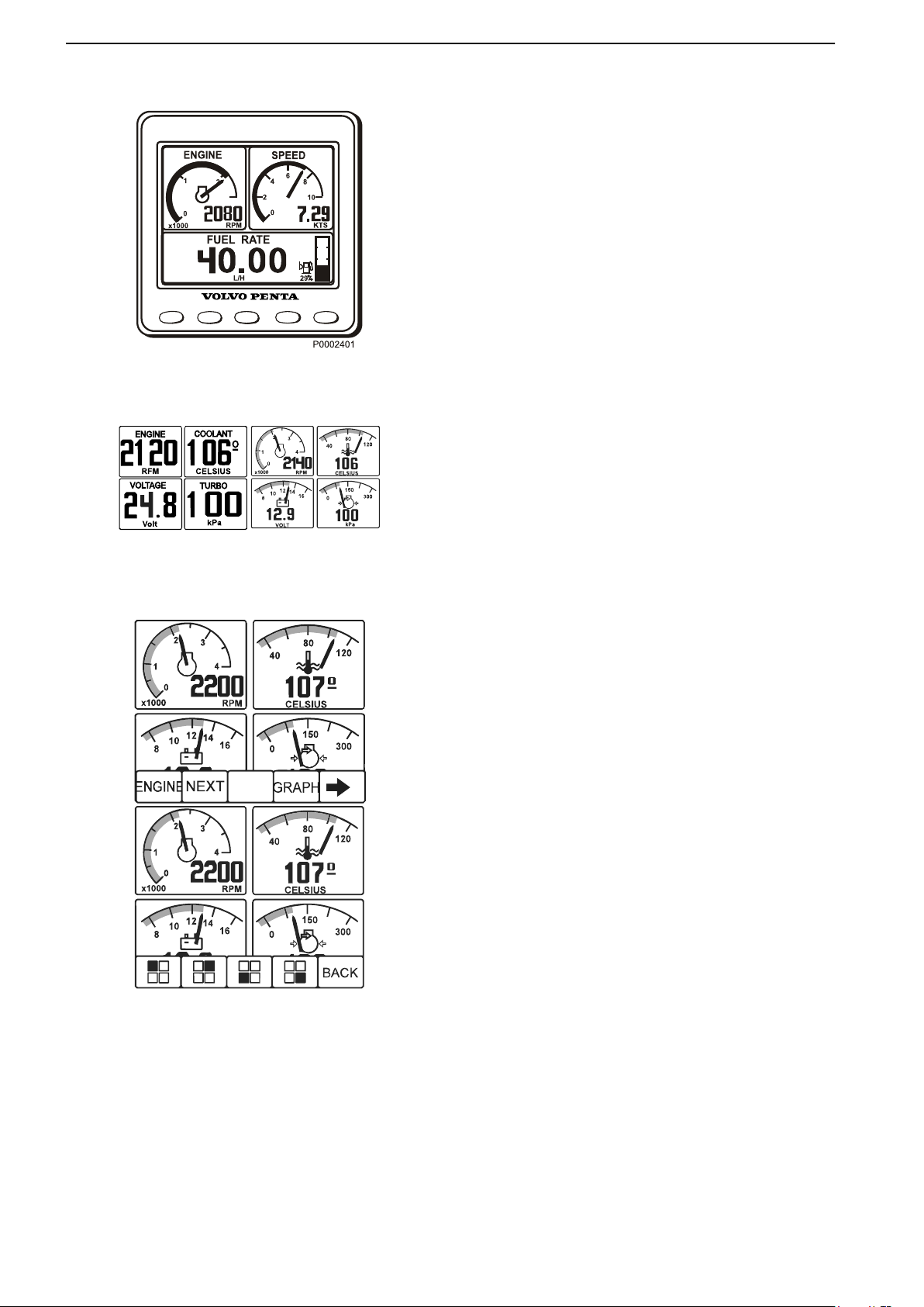
Configuration menu
Open the Configuration menu by holding down button
5 for at least 3 seconds. In this screen it is possible to
retrieve System information, enter various display settings, calibrate depth compensation and speed and
retrieve other system information.
47702088 - Downloaded from www.volvopenta.com 02/06/2011 18:54:55
Engine ignition must be switched on when changing
display settings or calibrating functions.
Navigate through the menu using the up and down
arrows, and select using the right arrow.
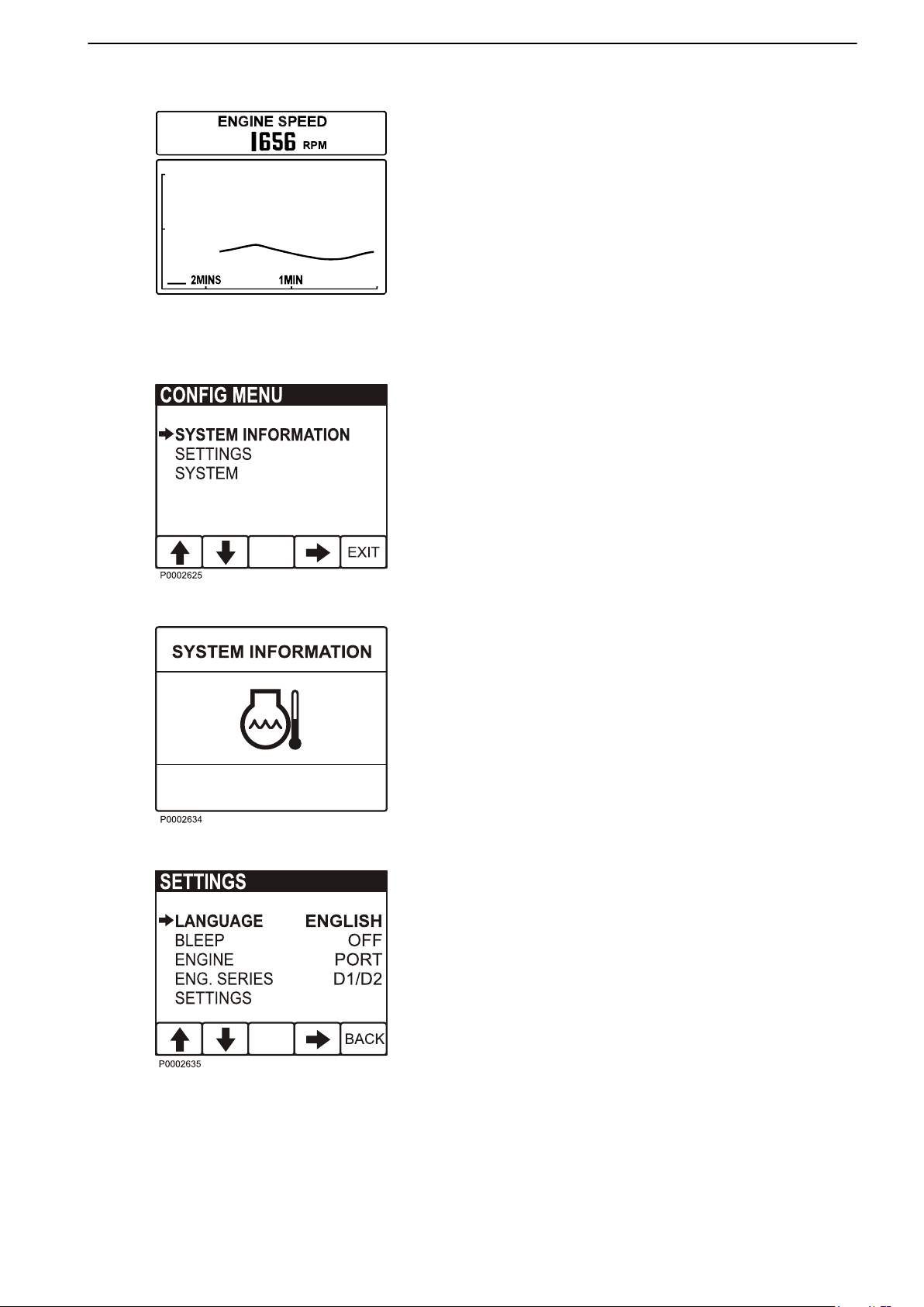
System Information
This screen shows the same information as that shown
in the tachometer display; refer to Instruments and
Controls page 11 for further information.
Alarm
When the system detects a fault, the display automatically switches to the System Information screen. For
further information, refer to Fault Handling page 25.
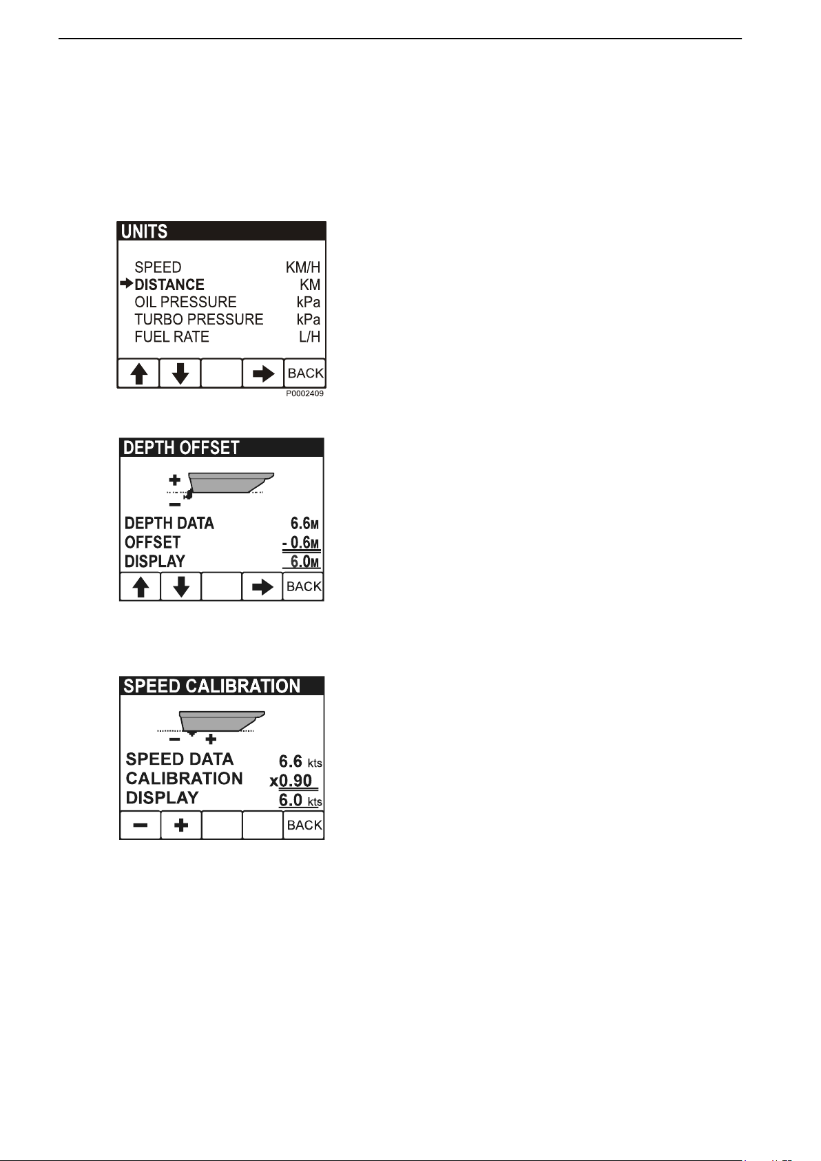
Settings
Language: setting the display language.
Bleep: setting button bleep On or Off.
Engine: setting the installation the display forms part
of, and the engine to be shown in the display (single,
port, starboard or twin).
Eng. series: setting the engine series for the display
(D1/D2, <D2). The display is factory set for engines
larger than D1/D2, therefore the display must be re-set
before it can be used on D1/D2 engines.
Display: setting speed indicator and tachometer intervals.
47702088 05-2011 15
Page 18
P0003002
P0003005
Instruments and Controls
- Rpm intervals, 2500–9000 rpm in 500 rpm stages.
Set 4000 rpm.
- Speed, on/off.
- Speed intervals, 10–100 knots in 10 knot stages.
- Graph intervals: 2 min, 10 min, 30 min, 60 min, 2 h,
4 h or 8 h.
- Speed (Speed): KNOTS, MPH, KM/H
Units: Selection of operational information units to be
shown (this menu is only displayed if “Local” is selected
in the settings menu: “Local” must always be selected
for D1/D2 engines).
- Distance: NM, MILE, KM
- Oil pressure/Turbo pressure: kPa, psi
- Fuel rate: L/H, GAL/H, IGAL/H
- Temperature: °C, °F
Calibration: the engine must be switched on during
calibration.
47702088 - Downloaded from www.volvopenta.com 02/06/2011 18:54:55
Depth compensation
Setting the Volvo Penta echo sounder. The echo-sounder can be installed anywhere between the waterline
and the boat's deepest point. Set the deviation – off set
– so that the display value shows one of these points.
To adjust the value up (+), set the distance between
the echo-sounder and the waterline; to adjust the value
down (–), set the distance between the echo-sounder
and the boat's deepest point. The value can be set in
0.1 unit stages.
Store the set value by depressing BACK (button 5).
Speed factor
The speed factor must be set while the boat is under
way. Compare the displayed boat speed value with
GPS data (or another boat) and adjust the speed factor
until the values agree.
The speed sensor calibration value can be adjusted
upwards (+) or downwards (-) in stages of 0.01 units
(+ or - 1%). Store the adjusted value by depressing
BACK (button 5).
16 47702088 05-2011
Page 19
N
F
R
T
T
1
P0002427
Instruments and Controls
Controls
This section describes the controls Volvo Penta sells
for your engine. Contact your dealer if your boat is
equipped with controls other than those described
here, and you feel uncertain about their function.
Maneuvering
A single-lever control operates both gearshift and
throttle functions from the same lever.
The engine can only be started with the control lever
in the neutral position.
N = Neutral position. Reverse gear/drive disengaged
and engine at idle.
F = Reverse gear/drive engaged for movement
ahead.
R = Reverse gear/drive engaged for movement
astern.
T = Engine rpm control (throttle).
47702088 - Downloaded from www.volvopenta.com 02/06/2011 18:54:55
Disconnecting the gearshift function
The gearshift function can be disconnected so that the
control lever only operates the throttle.
1 Put the control lever in neutral (N).
2 Depress the neutral button (1), and keep it
depressed at the same time as the lever is moved
forward.
3 Release the neutral button, the shift function is dis-
engaged and the lever only influences engine revolutions.
The gear shift function is reconnected automatically
when the lever is returned to the neutral position.
CAUTION!
Take care not to engage the gear by mistake.
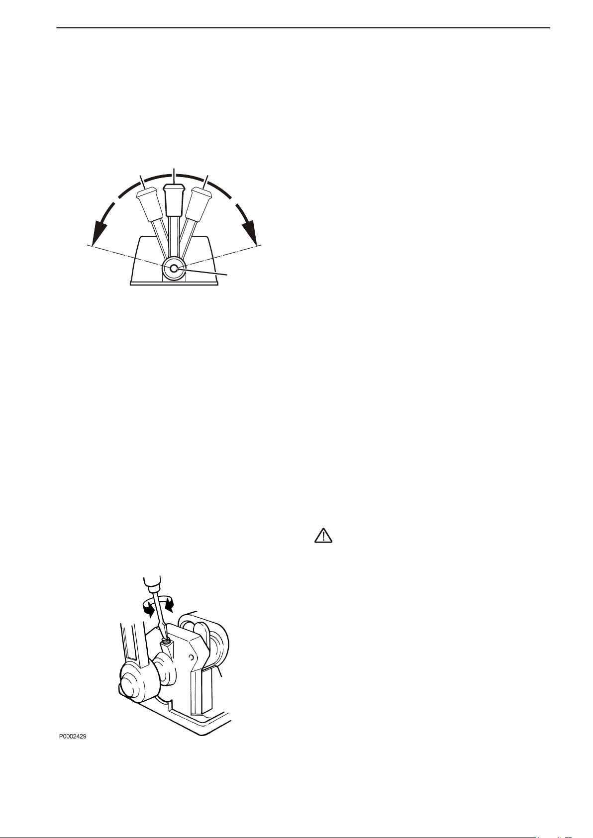
Adjusting the friction brake
The lever is fitted with a friction brake to allow adjustment for easier or stiffer movement as required. The
friction brake only affects movement of the throttle control lever.
1 Lift away the cover from the control. On side-
mounted controls the lever must be removed first.
2 Move the lever to the half throttle/astern position.
3 Adjust the friction brake by turning the screw clock-
wise (+) for stiffer lever movement, and counterclockwise (-) for easier movement.
4 Replace the cover and the lever.
47702088 05-2011 17
Page 20
Starting
1
0
P0005851
1
P0007529
Make a habit of visually checking the engine, engine bay and transmission before start. This will help you to
discover quickly if anything abnormal has happened, or is about to happen. Also check that instruments and
warning displays show normal values when you have started the engine.
To minimize cold start smoke we recommend the installation of an engine heater or engine bay heater if temperatures below +5°C (41°F) are encountered.
WARNING!
Never use start spray or similar products as starting aid. Explosion risk!
Before Starting
Check the engine and transmission oil levels.
•
Check coolant level.
•
Open the sea cock.
•
Open the fuel cock.
•
Turn the main switch(es) on.
•
IMPORTANT!
Never disconnect the current with the main switches
when the engine is running. The alternator and electronics could be damaged.
47702088 - Downloaded from www.volvopenta.com 02/06/2011 18:54:55
Start the engine bay fan, where fitted, and allow it to
•
run for at least four minutes.
Check that there is sufficient fuel for the planned trip.
•
Starting the Engine
Activate the control panel by depressing the on/off button (1). The Volvo Penta logo is displayed in the window. Two audible signals are sounded to indicate the
system is ready and that the engine may be started.
18 47702088 05-2011
Page 21
!
!
+
-
0
3
2
1
4
RPMX1000
P0008437
4
P0007951
Starting
Check the tachometer
If an operational fault occurs an audible alarm will
sound and a symbol will flash in the tachometer window. Refer to the Fault Handling page 25 chapter for
more detailed information and recommended actions.
Check the alarm instrument (accessory).
The lamps in the alarm instrument light up each time the
ignition is turned on. Check that all lamps light up and
then extinguish. If any lamp flashes, a fault has been
registered; refer to the Fault Handling page 25 chapter for more detailed information and recommended
actions.
Start the engine
Press the start button (4). Release the start button as
soon as the engine starts.
The pre-heating symbol is displayed in the tachometer
window. Pre-heating is automatic and lasts for 20 seconds.
Pre-heating only takes place if engine temperature is
below 50° (122° F).
Pre-heating may be activated before the engine is
started by depressing the start button (4) for a short
moment. Pre-heating will continue for 20 seconds. The
pre-heating symbol is displayed in the tachometer window.
47702088 - Downloaded from www.volvopenta.com 02/06/2011 18:54:55
Read off the instruments and warm up the
engine
Allow the engine to idle for the first 10 seconds. Read
off the instruments and check that they show normal
values. Check that no warning lamps are flashing. If any
lamp flashes, a fault has been registered; refer to the
Fault Handling page 25 chapter for more detailed
information and recommended actions.
Warm up the engine at low speed and low load, so that
normal working temperature is reached before full
power is applied.
47702088 05-2011 19
Page 22
Operation
0
3
2
1
4
RPMX1000
SYSTEM INFORMATION
1
2
P0007519
Learn to handle the engine, controls and other equipment in a safe and proper manner before casting off on your
maiden voyage. Remember to avoid sudden and extreme rudder maneuvers and gear shifts. There is a risk for
passengers and crew falling over or falling overboard.
WARNING!
A rotating propeller can cause serious injury. Check that nobody is in the water before engaging ahead or astern.
Never drive near bathers or in areas where people could be in the water.
Reading the Instruments
Read off the instruments and alarm display immediately after start, and then regularly during operation.
Alarms
If an alarm is tripped, an audible alarm will sound and
a symbol will flash in the tachometer window (1).
If optional equipment such as alarm instruments or an
EVC display are installed, the relevant warning lamp
will flash there also.
47702088 - Downloaded from www.volvopenta.com 02/06/2011 18:54:55
1 Reduce engine speed to idle.
2 Cancel the alarm by depressing the multi-function
button (2).
The audible alarm will be silenced. The symbol will
be lit continuously until the fault is remedied
3 Take the necessary action: refer to the Fault Han-
dling page 25 section.
20 47702088 05-2011
Page 23

1
2
3
P0005856
Operation
Maneuvering
Shifting between ahead and astern must be done at
idle revolutions. Shifting at higher revolutions can be
uncomfortable for those on board and cause unnecessary stress to the transmission or make the engine
stall.
Always shift between ahead and astern in
the following manner:
1 Reduce engine revolutions to idle and allow the
boat to lose most of its speed.
2 Move the control lever to the neutral position with
a quick, firm movement. Pause a moment.
3 Move the control lever back with a quick, firm
movement and increase revolutions.
47702088 - Downloaded from www.volvopenta.com 02/06/2011 18:54:55
47702088 05-2011 21
Page 24

Operation
Sailing
When sailing, set the control lever to astern if a folding
propeller is fitted.
Is a fixed propeller is fitted the control lever should be
set in neutral or reverse. When using a fixed propeller
and sailing with the control lever set to reverse the
speed is slowed down though less noise is being
made.
Cruising Speed
47702088 - Downloaded from www.volvopenta.com 02/06/2011 18:54:55
Avoid operations at full throttle for best fuel economy.
We recommend a cruising speed that is around
500-1000 rpm below the maximum rpm at top speed
(full throttle).
Depending on the type of hull, choice of propeller, load
and sea state etc., maximum revolutions at top speed
may vary, but should be within the full throttle range;
refer to the Engines section.
22 47702088 05-2011
Page 25

Engine Shutdown
1
3
2
P0014272
1
0
P0005914
Allow the engine to run at low idle, in neutral, for a few minutes after operations are completed. In this way afterboiling is avoided at the same time as temperature equalization takes place. This is especially important when
the engine has been run under heavy load at high rpm .
Stop the Engine
Press the Stop button (3) until the engine stops running.
Press the On/Off button (1) to cut the power to the system.
If the engine is stopped and the ignition still turned on,
an alarm sounds after 10 seconds to prevent the ignition is left on unintentionally and the battery will
become discharged.
Silence the alarm by turning the ignition off, or reset
the alarm with the multifunction button (2) if the ignition
is to be turned on.
47702088 - Downloaded from www.volvopenta.com 02/06/2011 18:54:55
Auxiliary stop
If the engine cannot be stopped in a normal procedure,
it is possible to stop the engine via the auxiliary stop
mounted on the side of the engine.
After Engine Shutdown
Check the engine and engine bay for leakages.
•
Close the fuel tap.
•
Close the sea cock where fitted.
•
Take an hour meter reading and carry out preven-
•
tive maintenance according to the maintenance
schedule.
Turn off the main switch before any long stoppage.
•
47702088 05-2011 23
Page 26

C
0
10
10
F
32
50
10
20
70
20
20
60
P0005905
Engine Shutdown
Operation break with the boat in water
If the boat is not used, but left in the water, the engine
must be warmed up at least once every fortnight. This
prevents corrosion damage in the engine.
If you expect the boat to be unused for two months or
more, it must be laid up, please refer to Stor-
age page 64
Operation break with the boat out of water
Where boats are kept laid up on land when not in use,
there is a lower level of galvanic corrosion protection
due to oxidation on the sacrificial anodes. Before
launching the boat the sacrificial anodes on the drive
and shield must be cleaned with emery paper to
remove any oxidation.
If you expect the boat to be unused for two months or
more, it must be laid up, please refer to Stor-
age page 64.
IMPORTANT!
Use emery paper. Do not use a wire brush or other
steel tools when cleaning, as these may damage the
galvanic protection.
47702088 - Downloaded from www.volvopenta.com 02/06/2011 18:54:55
Cold Weather Precautions
If the engine bay cannot be kept frost free, the raw
water system must be drained and the freshwater system coolant must have sufficient frost protection to
prevent frost bursting; refer to Seawater System,
Draining page 48 and Maintenance page 43
respectively for more detailed information.
Check the charge status of the battery. A poorlycharged battery can freeze and burst.
24 47702088 05-2011
Page 27

Fault Handling
0
3
2
1
4
RPMX1000
SYSTEM INFORMATION
1
2
P0007519
Despite regular maintenance according to the maintenance schedule and perfect operation conditions faults may
occur which must be attended to before the boat can travel further. This chapter describes alarms and fault
handling.
If an operational fault arises an audible alarm will
sound and a symbol will flash in the tachometer window(1) If optional equipment such as an alarm monitor or an EVC display are installed, the relevant warning lamp will flash there also.
Cancel the alarm by depressing the multi-function
button (2). The audible alarm will be silenced. The
symbol will be lit continuously until the fault is remedied.
This chapter describes faults and actions to be taken.
CAUTION!
Read the safety precautions for maintenance and
service in the Safety Information chapter before starting work.
47702088 - Downloaded from www.volvopenta.com 02/06/2011 18:54:55
47702088 05-2011 25
Page 28

Fault Handling
Coolant Temperature
The coolant temperature lamp is lit if the coolant temperature is too high.
IMPORTANT!
Continued operations with too-high engine temperature may cause serious engine damage.
• Check coolant level. Refer toCoolant Level,
Checking and Topping Up page 45.
• Check that the raw water filter, where such is
fitted, is not clogged. Refer to Seawater Filter,
Check and Cleaning page 51.
• Check the impeller in the seawater pump. Refer
toImpeller, Check and Change page 49.
If the alarm continues despite the above actions being
carried out, run the engine at low revolutions and drive
the boat to the nearest service workshop for repair.
47702088 - Downloaded from www.volvopenta.com 02/06/2011 18:54:55
Oil pressure
If the oil pressure lamp lights up during operations, the
engine oil pressure is too low.
IMPORTANT!
Continued operations with too-low oil pressure will
cause serious engine damage.
• Checking Engine Oil Level, refer to Oil level,
checking and topping up page 39.
• Check that the oil filter is not blocked. Change
the oil filter as necessary; refer to Engine oil and
engine oil filter, changing page 40.
• Please contact a Volvo Penta workshop if the
fault remains.
Battery
The charging lamp lights up when the alternator stops
charging the batteries, which may result from a fault
in the electrical system or the need to tension the
alternator drive belt.
• Check belt tension. Refer to Drive Belt, Check
and Change page 37.
• Check to see if there are no short circuit, chafed
wires or wires with loose connections.
• Check the fluid level in the battery; refer to Bat-
tery, Maintenance page 53.
• Please contact a Volvo Penta workshop if the
fault remains.
26 47702088 05-2011
Page 29

1
2
3
4
5
6
7
P0004761
Fault Handling
System failure
The "system fault" symbol is displayed when there is
a short circuit or cable break.
The symbol shows if the ignition is left on, refer to
Engine Shutdown page 23.
• Check to see if there are any chafed wires or
wires with loose connections.
• Please contact a Volvo Penta workshop if the
fault remains.
Fuel level
The fuel level symbol is displayed when less than 20%
fuel remains in the tank if a fuel level sensor is installed (optional equipment).
47702088 - Downloaded from www.volvopenta.com 02/06/2011 18:54:55
Auxiliary alarm
Alarm for auxiliary sensors (optional equipment).
Alarm Display (optional instrument)
1 The fuel level symbol lights up during operation
when less than 20% fuel remains in the tank if a
fuel level sensor is installed (optional equipment).
2 The battery lamp lights up if the alternator is not
charging.
3 The coolant temperature lamp lights up when
the coolant temperature is too high.
4 This indicator is not activated for the engine.
5 This indicator is not activated for the engine.
6 The "System Failure lamp" will light up at short
circuit, broken wire and AUX failure.
7 If the oil pressure lamp lights up during opera-
tion, the oil pressure in the engine is too low.
47702088 05-2011 27
Page 30

Fault Handling
Fault Tracing
A number of symptoms and possible causes of engine malfunctions are described in the table below. Always
contact your Volvo Penta dealer if any problems occur which you cannot solve by yourself.
NOTICE! Read the safety regulations for care and maintenance in the Safety Information page 6 chapter before
work you start work.
Symptoms and possible causes
Start motor will not turn, or turns slowly 1, 2
Engine does not start 3, 4, 5, 6, 7, 8
Engine starts but stops again 5, 6, 7, 8
Engine is difficult to start 5, 6, 7, 8
Engine does not reach correct operating speed at full throttle 6, 7, 8, 9, 10, 11, 12, 17
Engine knocks 13
Engine runs roughly 5, 6, 7, 8, 12, 13
Engine vibrates 17, 18
High fuel consumption 9, 10, 12, 14, 17
Black exhaust smoke 4, 12, 14, 17
Blue or white exhaust smoke 14, 24
Lubrication oil pressure too low 15, 16
Coolant temperature too high 19, 20, 21, 22, 23
No charge, or poor charge 1, 25
1. Flat battery
2. Poor contact/open circuit in cables
3. The stop lever is pulled out
4. Insufficient preheat
5. Lack of fuel
6. Blocked air filter
47702088 - Downloaded from www.volvopenta.com 02/06/2011 18:54:55
7. Air in the fuel system
8. Water/contamination in fuel
9. Boat abnormally loaded
10. Fouling on hull, drive or propeller
11. Limited movement in engine control lever
12. Insufficient air supply to engine
13. Coolant temperature too high
14. Coolant temperature too low
15. Oil level too low
16. Blocked oil filter
17. Faulty / wrong propeller
18. Faulty engine mounting
19. Coolant level too low
20. Blocked raw water inlet, lines or filters
21. Circulation pump drive belt slipping
22. Faulty impeller
23. Faulty / wrong thermostat
24. Oil level too high
25. Alternator drive belt slipping
28 47702088 05-2011
Page 31

In Case of Emergency
P0002107
Despite regular service in accordance with the planned
maintenance schedule and perfect operating conditions, faults may occur that must be remedied before
the boat can continue its trip. This chapter provides
advice on how to remedy a number of conceivable
faults.
If a fault occurs, confirm any fault alarm and take the
necessary actions. See this chapter and refer to the
Fault Handling page 25 chapter.
Starting Using Auxiliary
Batteries
WARNING!
Explosion hazard. Batteries contain and give off an
explosive gas which is highly flammable and explosive.
A short circuit, open flame or spark could cause a violent explosion. Ventilate well.
47702088 - Downloaded from www.volvopenta.com 02/06/2011 18:54:55
WARNING!
Never confuse the positive and negative poles on the
batteries. Risk of arcing and explosion.
1 Check that the auxiliary battery has the same volt-
age as the engine system voltage.
2 Connect the red positive cable to the plus (+) ter-
minal on the discharged battery and then to the plus
terminal on the auxiliary battery.
3 Connect the black start cable to the minus (–) ter-
minal on the auxiliary battery and to a place a little
distance away from the discharged battery, e.g. the
start motor's negative terminal.
WARNING!
Under no circumstances may the black jumper cabel
(–) come in contact with the positive connection on the
starter motor.
4 Start the engine and let it run at fast idle for approx-
imately 10 minutes to charge the batteries. Make
sure there is no extra equipment connected to the
electrical system.
47702088 05-2011 29
Page 32

In Case of Emergency
WARNING!
Working with or going close to a running engine is a
safety risk. Watch out for rotating components and hot
surfaces.
WARNING!
Do not touch the connections during the start attempt:
Risk of arcing.
Do not bend over any of the batteries either.
5 Turn off the engine. Remove the start cables in the
exact opposite order to their connection.
47702088 - Downloaded from www.volvopenta.com 02/06/2011 18:54:55
30 47702088 05-2011
Page 33

Maintenance Schedule
Your Volvo Penta engine and its equipment are designed for high reliability and long life. The engines are built to
withstand the marine environment, but also to have the smallest possible environmental impact. If the engine and
transmission are serviced regularly according to the schedule, these qualities will be retained and unnecessary
malfunctions will be avoided.
Warranty inspection
During the initial period of use a special warranty inspection - a First service inspection - must be carried out by
an authorized Volvo Penta workshop. Instructions regarding when this must be done can be found in the Warranty
and service book.
Extended protection for leisure use
Volvo Penta offers extended protection for marine diesel engines, including power trains, applicable only to leisure
boats. For the warranty to be valid, all prescribed services must have been carried out at the owner's expense by
an authorized Volvo Penta dealer or service workshop before the 12 month warranty period has expired. Further
instructions are contained in the Warranty and service book.
C
=
Clean
R
=
Replace
A
=
Adjust
L
=
Lubricate
I
=
Inspect (Clean, Adjust, Lubricate or Replace if necessary)
First service inspection, after 20–50 running hours
Transmission, oil level I
Coolant level and antifreeze mixture I
Drive belt (tension) I
Seawater filter I C
Instrument panel function I
Start and warm up engine
Engine and transmission, oil / fuel / water leakage I
Engine and transmission, abnormal noises I
47702088 - Downloaded from www.volvopenta.com 02/06/2011 18:54:55
Stop Engine
Engine oil and oil filters L
Restart engine
Oil pressure / oil leakage I
1)
Or within 180 days of the date of delivery, or the end of the first season, whichever comes first.
Daily, Before First Start
Engine and engine room. General inspection I
Checking Engine Oil Level I
Check coolant level. I
1)
47702088 05-2011 31
Page 34

Maintenance Schedule
Every 14 days
Drive belts, wear I
Seawater Filter, Check and Cleaning I C
Fuel pre-filter, draining water / contamination I
Batteries, electrolyte level I
Reverse gear, oil level I
S-drive, oil level I
Every 200 hours / at least once a year, included in extended protection
D1 Engine oil and oil filters
1)
Reverse gear, oil R
Reverse gear, propeller shaft seal I
S-drive, oil R
S-drive/reverse gear, corrosion protection I
1)
Oil change intervals vary, depending on engine type, oil grade and sulfur content of the fuel. Se avsnitt Oil
Grade and Oil Change Interval.
R
Every 500 operating hours / at least once per year; included in extended warranty
D2 Engine oil and oil filters
1)
Fuel pre-filter and fuel fine filter R
Idle I
Seawater pump impeller I
Vaccum Valve, Cleaning C
1)
Oil change intervals vary, depending on engine type, oil grade and sulfur content of the fuel. Se avsnitt Oil Grade
and Oil Change Interval.
Once per year; included in extended warranty
Folding Propeller C
47702088 - Downloaded from www.volvopenta.com 02/06/2011 18:54:55
S-drive, Rubber Sealing between Drive and Hull I
Every 500 operating hours / at least once every 2 years
Heat exchanger C
Injectors I
Valve clearance A
R
Every 4 years
Coolant R
Every 500 operating hours / at least once every 5 years
Reverse gear, propeller shaft seal R
Every 7 years
S-drive, Rubber Sealing between Drive and Hull R
32 47702088 05-2011
Page 35

Maintenance
1
2
3
4
5
6
P0008052
7
8
9
10
11
12
13
14
P0008053
This chapter contains general technical information and instructions on how the prescribed maintenance items
must be carried out. Read through the instructions carefully before starting work. The times when maintenance
items must be carried are indicated in the Maintenance Schedule page 31.
Read through the safety precautions for maintenance and service in the Safety Information page 4 chapter before
work on the engine is begun.
WARNING!
Care and maintenance work should be done with the engine stopped unless otherwise specified. Stop the engine
before opening or removing the engine hatch/hood. Make it impossible to start the engine by removing the start
key and cutting the system voltage with the main switches.
D1-20 with MS10A reverse gear
D1-20 with MS10A reverse gear
47702088 - Downloaded from www.volvopenta.com 02/06/2011 18:54:55
1 Coolant filling
2 Heat exchanger
3 Relay box
4 Alternator
5 Starter motor
6 Oil dipstick, reverse gear
7 Air filter/air intake
8 Fuel hand pump
9 Oil filler, engine
10 Oil dipstick, engine
11 Fuel filter
12 Oil filter
13 Injection pump
14 Raw water pump
47702088 05-2011 33
Page 36

1 2
3
4
5 6
7
P0008054
8
9
11
10
12
13
14
15
P0008055
Maintenance
D1-30 with MS15A reverse gear
D1-30 with MS15A reverse gear
1 Coolant filling
2 Heat exchanger
3 Relay box
4 Alternator
5 Starter motor
6 Oil cooler, reverse gear
7 Oil dipstick, reverse gear
8 Air filter/air intake
9 Fuel hand pump
10 Oil dipstick, engine
11 Oil filler, engine
12 Fuel filter
13 Oil filter
14 Injection pump
15 Raw water pump
47702088 - Downloaded from www.volvopenta.com 02/06/2011 18:54:55
34 47702088 05-2011
Page 37

1
2
3
4 5
6
7
8
P0008056
9
10
11
12
13
14
15
16 17
18
19
P0008057
Maintenance
D2-40 with 130S sailboat drive
1 Coolant filling
2 Heat exchanger
3 Relay box
4 Alternator
5 Starter motor
6 Sea cock, S-drive
7 Cooling water inlet, S-drive
8 Folding propeller
D2-40 with 130S sailboat drive
47702088 - Downloaded from www.volvopenta.com 02/06/2011 18:54:55
9 Oil dipstick, S-drive
10 Air filter/air intake
11 Fuel hand pump
12 Oil dipstick, engine
13 Oil filler, engine
14 Sacrificial anodes
15 Oil drain, S-drive
16 Fuel filter
17 Oil filter
18 Injection pump
19 Raw water pump
47702088 05-2011 35
Page 38

2
1
P0007521
Maintenance
Engine, General
General inspection
Make a habit of visually checking the engine and
engine bay before starting, and after operations when
you have stopped the engine. This will help you to discover abnormalities quickly, or if something is about to
happen.
Look especially carefully for oil, fuel and coolant leakages, loose bolts, worn or poorly-tensioned drive
belts, loose cable connections, damaged electrical
cables and hoses. This inspection only takes a few
minutes and can prevent serious malfunctions and
expensive repairs.
WARNING!
Accumulations of fuel, oil and grease on the engine or
in the engine room is a fire hazard and must be
removed immediately they are detected.
47702088 - Downloaded from www.volvopenta.com 02/06/2011 18:54:55
WARNING!
If an oil, fuel or coolant leak is detected, the cause must
be investigated and the fault rectified before the engine
is started.
Never direct the jet from a high-pressure washer at
seals, rubber hoses or electrical components. Never
use the high pressure setting for engine cleaning.
Air Filter, Change
1 Loosen the hose clamp (1) and undo the bolt (2)
and remove the filter.
Make sure that contaminants do not enter the
engine.
2 Install the new filter; fasten with the hose clamp and
the bolt.
36 47702088 05-2011
Page 39

3
1
2
10mm
PREHEAT
START
BATT
P0007520
Maintenance
Drive Belt, Check and Change
WARNING!
Stop the engine before doing any maintenance work.
Check belt tensions and condition regularly. A belt that
is tensioned too tightly may damage bearings, while a
belt too-loosely tensioned may slip.
Check and adjust the belt after operation, while the belt
is still warm.
A correctly-tensioned belt should be possible to
depress approx. 10 mm (0.4”) between the pulleys.
IMPORTANT!
Always replace a belt that appears worn or has cracks
(belts that work in pairs must always be changed
together).
Adjusting the drive belt
47702088 - Downloaded from www.volvopenta.com 02/06/2011 18:54:55
D1-30 and D2-40
1 Undo the alternator retaining bolts (1-2).
2 Using the adjuster screw (3), adjust the belt to the
correct tension.
3 Tighten the bolts (1-2) and check the tension.
Replacing the drive belt
1 Undo the alternator retaining bolts (1 and 2).
2 Press the alternator toward the engine block so
that the belt can be removed. Wipe clean the belt
grooves
3 Install the new belt. Adjust.
4 Check the belt tension again after a few hours'
operations.
IMPORTANT!
D1-30, D2-40: Ensure that the alternator belt is placed
in the groove closest to the alternator.
47702088 05-2011 37
Page 40

B
A
P0007955
Maintenance
Idling, adjustment
For engine idle revolutions, refer to the Engines section. Low idle revolutions may cause the engine to stall,
while higher idle revolutions cause extra stress on the
drive/reverse gear during shifting maneuvers.
Adjustment must be made while the engine is warm.
1 Put the control lever in neutral.
Check that the gap (A) is around 3 mm.
Undo locknut (B) and adjust screw (C) to give the
correct gap. Tighten the locknut.
2 Start the engine and let it idle with the control lever
in the neutral position.
WARNING!
Working with or going close to a running engine is a
safety risk. Watch out for rotating components and hot
surfaces.
(1)
47702088 - Downloaded from www.volvopenta.com 02/06/2011 18:54:55
3 Undo the locknut (D). Adjust to the correct revolu-
tions using the adjuster screw (E). Tighten the lock
nut.
4 Repeat item 1.
1. This item does not apply to boats with twin helm stations.
38 47702088 05-2011
Page 41

P0002089
MIN
MAX
1
2
P0007522
Maintenance
Lubrication System
Oil change intervals can vary depending on oil grade
and sulphur content of the fuel, please refer toTechni-
cal Data, Lubrication System.
Oil change intervals must never exceed a period of 12
months.
If you want longer oil change intervals than given in the
table Oil Grade and Oil Change Interval, the condition
of the oil must be checked by the oil manufacturers
through regular oil testing.
Oil level, checking and topping up
47702088 - Downloaded from www.volvopenta.com 02/06/2011 18:54:55
The oil level must be within the marked area on the oil
dipstick and must be checked daily before the first
start.
IMPORTANT!
Do not fill above the limit for max. oil level. Use only oil
of the recommended grade; refer to Technical Data,
Lubrication System.
1 Fill oil slowly through the oil filler on top of the
engine (1) or at the side (2).
2 Wait 5 minutes so that the oil has time to run down
into the engine.
3 Check the oil level again when the engine has
cooled.
47702088 05-2011 39
Page 42

P0007523
Maintenance
Engine oil and engine oil filter,
changing
Always follow the recommended oil change interval.
Use only oils of the recommended grades; refer to Oil
Grade and Oil Change Interval.
WARNING!
Hot oil and hot surfaces can cause burns.
1 Run the engine until warm so that the oil is easier
to pump. Stop the engine.
2 Connect an oil drain pump to the oil drain pipe.
Pump out the oil.
3 Unscrew the lubricating oil filter. Place a plastic bag
over the filter before it is unscrewed to avoid oil
spillage.
4 Check that the filter contact area on the engine is
clean.
47702088 - Downloaded from www.volvopenta.com 02/06/2011 18:54:55
5 Apply a film of oil on the new filter gasket. Screw
the filter on by hand until it touches the contact surface. Then tighten an extra half turn, no more!
6 Fill with oil to the correct level through the oil filler
on top or to the side of the engine. For oil quantity,
refer to the Technical Data, Lubrication System
section.
Start the engine. Run the engine until it reaches
normal operating temperature. Check that the low
oil pressure lamp goes out and that there are no
leaks around the oil filter.
7 Turn off the engine. Wait ten minutes before check-
ing the oil level. Top up as needed.
Hand in the old oil and oil filter to a re-cycling station.
40 47702088 05-2011
Page 43

P0003731
Maintenance
Fuel System
Only use the grades of fuel recommended in the fuel
specification, see Technical Data, Fuel System.
Always observe the greatest cleanliness during refuelling and work on the fuel system.
All work on the unit injectors of the engine must be
carried out by an authorized workshop.
WARNING!
Fire hazard. When carrying out work on the fuel system
make sure the engine is cold. A fuel spill onto a hot
surface or an electrical component can cause a fire.
Store fuel soaked rags so that they can not cause fire.
Engine Fuel Filter Replacement
47702088 - Downloaded from www.volvopenta.com 02/06/2011 18:54:55
1 Clean the filter bracket.
Avoid fuel spills by placing a plastic bag around the
filter
2 Unscrew the filter
3 Apply a film of oil on the new filter gasket.
4 Screw the filter on by hand until it touches the con-
tact surface. Then tighten an extra half turn, no
more!
5 Purge the fuel system, refer to the Fuel system,
bleeding page 42 section.
6 Start the engine and check for leaks.
7 Hand in the old filter to a re-cycling station.
47702088 05-2011 41
Page 44

1
2
3
4
P0007532
1
P0007533
Maintenance
Fuel system, bleeding
The fuel system must be purged after a filter change,
if the fuel tank has been run dry and after a long-term
stoppage.
1 Open the purge screw (1) on the fuel filter approx.
three turns. Avoid fuel spills; use rags to soak up
fuel at the purging point.
2 Pump fuel up with the hand pump (2) until fuel with-
out air bubbles can be seen. Continue pumping and
tighten the purging screw at the same time.
The pump inlet pipe contains a strainer (3) which
normally does not need to be cleaned since the
engine has a fuel pre-filter. If a fuel pre-filter is not
fitted, poor feed flow can be due to a blocked
strainer.
If either of the two O-rings (4) are damaged, they
must be replaced.
3 Start the engine and check for leaks.
47702088 - Downloaded from www.volvopenta.com 02/06/2011 18:54:55
Fuel pre-filter
The fuel pre-filter is an optional extra.
Draining
Wait a few hours after the enginehas been turned off
before draining the filter..
Position a container under the fuel filter. Drain offwater
and contaminants using the cock/plug at the bottom of
the filter bowl.
Replacing filter insert
1 Close fuel cock at the fuel tank. Position a contain-
erunder the fuel filter.
2 Remove the filter bowl by undoing screw (1).
3 Emptyand clean the filter bowl. Replace insert and
reinstallthe bowl.
4 Open fuel cock.
5 Vent the fuel system, please refer to sectionFuel
system, bleeding page 42.
6 Start the engine and check for leaks.
7 Depositthe old filter insert at a properly designated
disposal site.
42 47702088 05-2011
Page 45

Maintenance
Freshwater System
The freshwater system is the engine's internal cooling
system that ensures that the engine operates at the
correct temperature. It is a closed system that must
always be filled with a coolant mixture in order to protect the engine against internal corrosion, cavitation
and frost bursting.
IMPORTANT!
Coolant of a suitable chemical composition must be
used all year round. This applies even when there is
no risk for frost damage, so that the engine always has
complete corrosion protection.
The use of anti-corrosion agents alone is not permitted
in Volvo Penta engines. Never use water alone as the
coolant.
The corrosion protection additives become less effective over time, which means that the coolant must be
changed at regular intervals; refer to Maintenance
Schedule page 31. The cooling system must be
flushed whenever the coolant is changed, refer to
Freshwater system, Flushing.
47702088 - Downloaded from www.volvopenta.com 02/06/2011 18:54:55
Volvo Penta recommend ”Volvo Penta Coolant VCS,
Ready Mixed” or the concentrate ”Volvo Penta Coolant
VCS” mixed with pure water according to specifications, see Water Quality.
Volvo Penta Coolant VCS and VCS Ready Mixed are
based on organic acid technology (OAT). Using other
types of coolant, such as conventional or hybrid types,
can drastically reduce the heat transfer and result in
overheating of the engine.
47702088 05-2011 43
Page 46

Maintenance
Coolant, Mixing
WARNING!
All coolant is hazardous and harmful to the environment. Do not consume. Coolant is flammable.
IMPORTANT!
Different types of coolant must not be mixed with each
other!
Mix: 40% “Volvo Penta Coolant” (conc.
coolant)and 60% water
This mixture protects against internal corrosion, cavitation and frost bursting down to –28°C (–18°F). At60%
glycol concentration, the freezing point is lowered to –
54°C (–65°F).
Never mix more than 60% concentrate (Volvo Penta
Coolant) in the coolant. A greater concentration provides reduced cooling effect with the risk for overheating and reduced frost protection.
47702088 - Downloaded from www.volvopenta.com 02/06/2011 18:54:55
The coolant must be mixed with distilled, deionized
water. The water must fulfil the requirements specified
by Volvo Penta; refer toWater Quality.
It is extremely important that the system is filled with
the correct coolant concentration. Mix in a separate
clean vessel before filling the cooling system. Make
sure that the liquids mix.
44 47702088 05-2011
Page 47

MAX
MIN
MAX
MIN
P0007524
2
1
P0007525
Maintenance
Coolant Level, Checking and
Topping Up
WARNING!
Do not open the coolant filler cap when the engine is
warm, except in emergencies, this could cause serious
personal injury. Steam or hot fluid could spray out.
1 Turn the filler cap slowly counter-clockwise and
release any pressure from the system before
removing the cap completely.
2 Top up with coolant as necessary. The coolant level
must be between the MAX and MIN marks on the
expansion tank.
3 Screw on the filler cap.
When filling a completely empty system the coolant
level must be checked after the engine has been run
for an hour or so, as the system is self purging. Top up
with coolant as necessary.
47702088 - Downloaded from www.volvopenta.com 02/06/2011 18:54:55
Coolant, Draining
WARNING!
All coolant is hazardous and harmful to the environment. Do not consume. Coolant is flammable.
1 Connect a hose to the engine block drain tap (1)
and one to the heat exchanger drain tap (2).
2 Remove the filler cap on the expansion tank to
speed up coolant drainage.
3 Open the drain taps (1) and (2). Allow all the coolant
run out into a container.
4 Collect the old coolant and hand it to a to a re-
cycling station
The heat exchanger must be cleaned before new coolant is added.
47702088 05-2011 45
Page 48

3
2
P0007526
Maintenance
Heat Exchanger, Cleaning
WARNING!
All coolant is hazardous and harmful to the environment. Do not consume. Coolant is flammable.
Cooling performance is reduced by scaling in the heatexchanger. It should therefore be flushed when thecoolant is changed.
1 Drain the coolant, please refer to section Coolant,
Draining page 45.
2 Loosen the hose (3) and insert a hose into the filling
pipe on the heat exchanger. Rinse with fresh water
until the water which runs out of the drain tap (1)
and the engineblock (2) is clean. Let all the water
run out.
3 Close the draining points (1 and 2) . Fill up with-
coolant to the correct level. Put the filler cap back.
47702088 - Downloaded from www.volvopenta.com 02/06/2011 18:54:55
4 Fit the hose (3).
46 47702088 05-2011
Page 49

Maintenance
Seawater System
The raw water system is the engine's external cooling
system. On engines with drives, the raw water pump
sucks in water via the drive, through the control system's oil cooler to the raw water pump. The water then
passes through the raw water filter before being
pumped through the fuel cooler, intercooler, engine oil
cooler and heat exchanger. Finally the water is fed out
through the exhaust elbow, where it is mixed with the
exhaust gases.
On engines with reverse gears, the raw water pump
sucks in water via a raw water intake, after which the
water passes a raw water filter (extra equipment)
before being pumped through the intercooler, heat
exchanger, engine oil cooler and gearbox oil cooler.
Finally the water is fed out through the exhaust elbow,
where it is mixed with the exhaust gases.
WARNING!
Risk of water entry. Water will flow into the boat if any
hose, plug etc. located below the waterline is removed
when the boat is in the water. Always close the sea
cocks. If the boat does not have sea cocks the water
flow must be blocked in a safe manner. If this is not
possible, the boat must be drawn up on land before
work starts.
47702088 - Downloaded from www.volvopenta.com 02/06/2011 18:54:55
47702088 05-2011 47
Page 50

130S
MS10 / MS15
MS15
P0007978
1
1
2
2
3
3
4
4
5
5
5
6
9
7
7
8
8
Maintenance
Seawater System, Draining
WARNING!
Risk of water entry. Close the seawater cocks before
doing any work on the seawater system.
To prevent freeze bursting, the raw water system must
be drained during cold weather when there is a risk of
freezing. An alternative to draining is to keep the
engine bay warm using an approved heater fan.
47702088 - Downloaded from www.volvopenta.com 02/06/2011 18:54:55
Note that all raw water must be drained and that the
draining process must be adapted to suit the engine
installation and any auxiliary equipment connected to
it, such as a raw water filter (2), vacuum valve (8),
exhaust riser and drain tap (9) and silencer (7) etc.
1 Close the sea cock (1).
2 Remove the cover and the sealing plate on the raw
water filter (2).
3 Remove the cover (3) from the raw water pump and
let the water run out.
4 Open the drain tap (4) on the heat exchanger side
panel and drain off the water.
5 Loosen the hoses at the arrows (5) and empty them
of water.
6 Connect a hose to the drain tap on the riser (9) and
lead it into a container. Open the tap and drain off
the water. Close the tap.
7 Remove the hose (6) on the reverse gear oil cooler
and drain off the water.
8 Drain the silencer (7), the exhaust system and other
auxiliary equipment connected to the raw water and
exhaust systems.
9 Reinstall all hoses, the raw water pump cover and
the raw water filter cover and sealing plate. Close
the heat exchanger drain tap.
48 47702088 05-2011
10 Open the raw water tap when the boat is returned
to operations.
Check that no leakage exists in the raw water system.
Page 51

P0007527
Maintenance
Impeller, Check and Change
WARNING!
Risk of water entry. Close the seawater cocks before
doing any work on the seawater system.
1 Close the sea cock.
2 Remove cover on the seawa-ter pump. Remove
impeller .
If there are cracks or other defects the impeller must
be replaced.
3 Lubri-cate the pump housing and the inside of the
cover with a little glycerin.
IMPORTANT!
Impellern skadas om andra typer av smörjmedel än
glycerin används.
4 Reinstall the impeller using a clockwise rotating
movement.
47702088 - Downloaded from www.volvopenta.com 02/06/2011 18:54:55
5 Install the cover together with a new gasket. Open
the sea cock.
Always carry a spare impeller on board.
47702088 05-2011 49
Page 52

1
2
P0007530
Maintenance
Seawater System, Cleaning and
Inhibiting
The raw water system must be flushed with fresh
water, to prevent deposits and salt crystals from building up inside it. The system must also be conserved
when the boat is laid up for winter or out-of-season
storage so that it is protected from internal corrosion.
WARNING!
Risk of water penetration.
Cleaning and inhibiting the seawater system should be
carried out with the boat on land.
WARNING!
Working with or going close to a running engine is a
safety risk. Watch out for rotating components and hot
surfaces.
47702088 - Downloaded from www.volvopenta.com 02/06/2011 18:54:55
1 Open the sea cock (1).
2 Remove the hose from the sea cock (1) or from the
outlet side of the raw water filter (2) if such is fitted
to the engine.
3 Put the free end of the hose into a bucket of fresh-
water. Proceed with refilling.
IMPORTANT!
The impeller will be damaged if it is run dry.
4 Check that there is no one in the vicinity of the pro-
peller and that nothing risks being spattered by the
exhaust outlet.
5 Set the control lever to neutral and start the engine.
Let it run at fast idle for a few minutes. Stop the
engine.
6 Fill the bucket with an antifreeze solution (40%
Volvo Penta Coolant and 60% freshwater) and
arrange for the collection of the solution throughput.
7 Start the engine and let it idle. Stop the engine just
before the mixture is depleted. Repeat until the
entire system has been flushed with the mixture.
8 Reconnect the removed hose.
9 The system is now conserved. The glycol mixture
should remain in the system during storage.
Before launching the boat, drain the mixture and
hand it to a re-cycling station.
50 47702088 05-2011
Page 53

1
2
3
P0007528
Maintenance
Seawater Filter, Check and Cleaning
WARNING!
Risk of water entry. Close the seawater cocks before
doing any work on the seawater system.
If the water where the boat is used contains contaminants, seaweed, etc. the filter should be checked more
frequently than stated in the maintenance schedule.
Otherwise there is a risk that the filter may be blocked
resulting engine overheating.
1 Close the sea cock.
2 Unscrew the cover (1) and remove the sealing plate
(2).
3 Lift out the insert (3) and clean it.
4 Replace parts as illustrated.
5 Open the sea cock and check for leaks.
47702088 - Downloaded from www.volvopenta.com 02/06/2011 18:54:55
Vaccum Valve, Cleaning
Certain configurations have a vacuum valve installed
in the raw water system.
WARNING!
Risk of water entry. Close the seawater cocks before
doing any work on the seawater system.
1 Close the sea cock.
2 Remove the valve. Unscrew the hexagonal cover
(1).
3 The cover contains a membrane (2) and a gasket
(3). Clean all components.
4 Turn the cover upside down. First insert the mem-
brane and then the gasket.
5 Turn the valve housing upside down as well. Screw
on the hexagonal cover to around 2 Nm. If the cover
is screwed on too tightly the valve may stop working.
47702088 05-2011 51
Page 54

p0013054
Maintenance
Electrical System
The engine is equipped with a 2-pole electrical system
and an alternator. System voltage is 12V.
WARNING!
Always stop the engine and break the current using the
main switches before working on the electrical system.
Isolate shore current to the engine block heater, battery charger or accessories mounted on the engine.
Main switch
IMPORTANT!
Never disconnect the current with the main switches
when the engine is running, the alternator and electronics could be damaged.
The main switches must never be switched off before
the engine has stopped. If the circuit between the alternator and the battery is disconnected when the engine
is running, the alternator and electronics can be damaged. For the same reason the charging circuits must
never be re-connected with the engine running.
47702088 - Downloaded from www.volvopenta.com 02/06/2011 18:54:55
Fuses
The engine is equipped with a strip fuse.
The fuse cut the power if the electrical system
becomes overloaded.
If it is not possible to start the engine or if the gauges
stop working during operations the fuse may have
deployed.
IMPORTANT!
Always investigate the cause of the overload. If the
fuse trips frequently, contact an authorized Volvo
Penta workshop.
52 47702088 05-2011
Page 55

P0002107
-
+
P0002108
Maintenance
Electrical Connections
Check that electrical connections are dry, free from
oxide, and that they are securely tightened. Spray the
connections as necessary with water-repellent spray
(Volvo Penta universal oil).
Battery, Maintenance
WARNING!
Risk of fire and explosion. Never allow an open flame
or electric sparks near the battery or batteries.
47702088 - Downloaded from www.volvopenta.com 02/06/2011 18:54:55
WARNING!
Never confuse the positive and negative poles on the
batteries. Risk of arcing and explosion.
WARNING!
The battery electrolyte contains extremely corrosive
sulfuric acid. Protect your skin and clothes when charging or handling batteries.
Always use protective goggles and gloves. If battery
electrolyte comes into contact with unprotected skin
whas off immediately using plenty of water and soap.
If battery acid comes in contact with the eyes, flush
immediately with plenty of water and obtain medical
assistance without delay.
Connecting and disconnecting the battery
Connecting
1 Connect the + cable (red) to the + pole on the bat-
tery.
2 Connect the – cable (black) to the – pole on the
battery.
Disconnecting
1 Remove the – cable (black).
2 Remove the + cable (red).
47702088 05-2011 53
Page 56

P0002110
P0002107
Maintenance
Cleaning
Keep the batteries clean and dry. Contamination and
oxide on the batteries and battery poles can cause
stray currents, voltage drop and discharge, especially
in wet weather. Remove oxidation from the battery
poles and terminals, using a brass brush. Tighten the
terminals securely and grease them with terminal
grease or petroleum jelly.
Filling
The electrolyte level should be 5–10 mm (0.2– 0.4”)
above the cell plates in the battery. Top up with distilled
water as required.
After filling, the battery should be charged for at least
30 minutes by running the engine at idle.
Some maintenance-free batteries have special
instructions, which must be followed.
47702088 - Downloaded from www.volvopenta.com 02/06/2011 18:54:55
Battery, Charging
WARNING!
Risk of fire and explosion. Never allow an open flame
or electric sparks near the battery or batteries.
WARNING!
The battery electrolyte contains extremely corrosive
sulfuric acid. Protect your skin and clothes when charging or handling batteries.
Always use protective goggles and gloves. If battery
electrolyte comes into contact with unprotected skin
whas off immediately using plenty of water and soap.
If battery acid comes in contact with the eyes, flush
immediately with plenty of water and obtain medical
assistance without delay.
WARNING!
Never confuse the positive and negative poles on the
batteries. Risk of arcing and explosion.
IMPORTANT!
Observe the instruction manual for the battery charger
carefully. To avoid the risk of electrochemical corrosion
when an external charger is connected, the battery
cables should be removed from the batteries before
the charger is connected.
Always switch off the charging current before the
charging clips are removed.
54 47702088 05-2011
Page 57

P0002111
Maintenance
Charge batteries if they have become discharged.
•
During charging, unscrew the cell plugs but leave
them in the plug holes. Ventilate well, especially if
the batteries are charged in an enclosed space.
If the engine is not used for a longer period of time,
•
the batteries should be fully charged, then possibly
trickle charged (please refer to the battery manufacturer’s recommendations). Batteries are damaged by being left discharged, and can also freeze
and burst easier in cold weather.
Special instructions apply to boost charging. Boost
•
charging can shorten battery life, and should therefore be avoided.
Electrical Installations
47702088 - Downloaded from www.volvopenta.com 02/06/2011 18:54:55
An incorrectly-carried-out electrical installation may
generate leakage current from the electrical system.
Leakage current can in turn render galvanic protection
inadequate in respect of propellers, propeller shafts,
rudder posts, the keel etc., and may cause damage
through electrochemical corrosion.
WARNING!
Work on the low voltage circuits in the boats should be
done by a person with electrical training or knowledge.
Installation or work on land current equipment must
only be done by a competent electrician, in accordance
with local regulations for mains electricity.
47702088 05-2011 55
Page 58

Maintenance
The following must always be heeded:
1 If shore power is connected it must always be
ground protected ashore, never in the boat. Furthermore, the shore power installation should be
equipped with a ground fault interrupter.
The shore power installation (transformer, inverter,
battery charger etc.) must be designed for marine
use where the high-tension side is galvanically separated from the low-tension side.
2 Electrical cables must be run and clamped such
that there is no risk of exposure to chafing, damp or
bilge water.
3 Ground protection for radios, navigation instru-
ments, rudder, boarding ladders or other equipment
where separate cables for ground protection are
present, must be clustered to a common ground
connection (B) that is not connected to the engine
or transmission.
IMPORTANT!
Neither the engine nor transmission may ever be
used as a ground.
The S-drive is insulated electrically (A) from the
engine and may never be used as the ground or be
connected electrically to other equipment such as
radios, navigation equipment, rudder, and boarding
ladders.
47702088 - Downloaded from www.volvopenta.com 02/06/2011 18:54:55
4 The start battery must have a main switch (C) con-
nected to the battery's plus (+) side. The main
switch must break the circuit to all equipment and
be switched off when the boat is not in use.
5 If an auxiliary battery is used, a main switch must
be placed between the auxiliary battery's plus (+)
terminal and the circuit breaker panel for the boat's
electrical equipment. The main switch must break
the circuit to all equipment connected to the auxiliary battery and must be switched off when power is
no longer required. All equipment connected to the
auxiliary battery must have separate main
switches.
For simultaneous charging of two independent battery
circuits a separate charging distributor (accessory)
should be installed on the standard alternator.
56 47702088 05-2011
Page 59

P0007536
Maintenance
Reverse Gear
Oil level, checking and topping up
1 Start the engine and let it run on idle a few minutes.
2 Remove the dipstick by turning counter-clockwise.
3 Wipe the dipstick and reinsert it in the reverse gear
without screwing it in. Remove the dipstick and
check the oil level. The correct oil level is between
the MAX and MIN markings.
4 Top up the oil as required using the dip stick tube.
Please refer to section Technical Data page 71
for oil quality and capacity.
IMPORTANT!
Never over-fill the reverse gear. The oil level must
always be within the recommended range.
47702088 - Downloaded from www.volvopenta.com 02/06/2011 18:54:55
Reverse Gear, Oil Change
1 Pull out the oil dipstick.
2 Pump out the oil with the oil drain pump through the
oil dipstick hole.
3 Measure out the correct quantity of oil and fill
through the oil dipstick hole. For oil grade and quantity, refer to the Technical Data page 71 section.
4 Put the oil dipstick back in place.
IMPORTANT!
Never over-fill the reverse gear. The oil level must
always be within the recommended range.
47702088 05-2011 57
Page 60

Maintenance
Propeller Shaft Sealing, Check
If the boat is fitted with a Volvo Penta propeller shaft,
the propeller shaft seals must be lubricated before
launch and purged directly after launching.
Purge the glands by pressing them together, at the
same time as they are pressed down onto the shaft.
The press approximately 1 cm³ of water resistant
grease into the seal.
47702088 - Downloaded from www.volvopenta.com 02/06/2011 18:54:55
58 47702088 05-2011
Page 61

Maintenance
Drive
The S-Drive is equipped with a sacrificial anode that
prevents galvanic corrosion. The galvanic protection
can be disabled by incorrect electrical installations and
suchlike. Damage caused by so-called electrolytic corrosion can appear quickly and can often be extensive.
Read more about this in the Electrical Installa-
tions page 55 section.
Incorrectly performed stern drive painting or the wrong
type of hull paint may render the galvanic protection
ineffective. Read more about painting in the Stor-
age page 67 section.
Oil level, checking and topping up
Remove the oil dipstick by unscrewing it counter-clockwise. Wipe the oil dipstick dry and replace it into the
stern drive/reverse gear, without screwing it down. Pull
out the oil dipstick again and check the oil level. The
correct oil level is between the MAX and MIN marks.
47702088 - Downloaded from www.volvopenta.com 02/06/2011 18:54:55
If required, top up oil through the oil dipstick hole. For
oil grade and quantity, refer to the Technical
Data page 71 section
IMPORTANT!
Never overfill the stern drive with oil. The oil level must
always be within the marked area.
47702088 05-2011 59
Page 62

P0007537
Maintenance
Transmission Oil, Change
1 Pull out the oil dipstick.
2 Remove the plug from the propeller gear transmis-
sion housing and allow the oil to run out.
Check that the plug O-ring is fault free; replace as
necessary.
3 Install the plug and O-ring.
4 Fill with oil to the correct level through the oil dip-
stick hole. For oil grade and quantity, refer to the
Technical Data page 71 section.
It is also possible to replace oil without laying up the
boat, e.g. if the oil change interval is reached during
the season. Pump out the oil through a suction pipe
using an oil drain pump – this method leaves approx.
0.5 liter (0.15 US gal) remaining in the stern drive. Fill
with oil to the correct level through the oil dipstick hole.
For oil grade, refer to the Technical Data page 71
section.
47702088 - Downloaded from www.volvopenta.com 02/06/2011 18:54:55
The oil should have a golden brown nuance. If the oil
is gray, water has entered the stern drive. In this case
let a Volvo Penta workshop carry out checks on the
stern drive.
60 47702088 05-2011
Page 63

2
1
P0007538
P0003085
Maintenance
Corrosion protection, checking and
changing
Check the sacrificial anode (1) on the stern drive and
the three sacrificial anodes (2) on the propeller regularly. Replace with new anodes when approximately
1/3 of an anode has corroded away.
When the boat is stored ashore, corrosion protection
deteriorates due to oxidization of sacrificial anodes in
contact with air. Even new anodes may have surface
oxidation. Before launching the sacrificial anodes must
be cleaned with emery cloth.
IMPORTANT!
Use emery paper. Do not use a wire brush or other steel
tools when cleaning, as these may damage the galvanic
protection.
Zinc in salt water.
•
Magnesium in freshwater.
•
47702088 - Downloaded from www.volvopenta.com 02/06/2011 18:54:55
Aluminum when the boat is used primarily in salt
•
water and sometimes in brackish water
Remedy any damaged stern drive paintwork according
to the instructions in the Storage page 67 section.
Replacing sacrificial anodes
1 Remove the sacrificial anodes and thoroughly
scrape clean the contact surfaces on the stern drive
and propellers.
2 Apply thread locking fluid to the bolts to the propel-
ler sacrificial anodes.
3 Install the new sacrificial anodes and fasten them
to ensure good metallic contact.
Rubber Sealing
Check the rubber seal between the drive and the hullregularly for cracks and wear.
IMPORTANT!
The seal must be changed everyseven years or earlier
if it is defective. This workshould be carried out by an
authorized workshop.
47702088 05-2011 61
Page 64

A
B
C
1
5
4
3
2
1
2
3
5
7
6
8
8
5
4
1
P0007539
Maintenance
Propeller
The propeller must be cleaned and greased once
yearly. Remove the propeller and clean all parts thoroughly. Brush water resistant grease on the propeller
blade cogs and bearing surfaces so that the propeller
folds easily. Also brush water resistant grease on pins,
spacer sleeves (stern drive), propeller shaft and in the
propeller hub.
47702088 - Downloaded from www.volvopenta.com 02/06/2011 18:54:55
WARNING!
Make sure the engine can not start during work on propeller(s); remove ignition key(s) and shift drive into forward or reverse.
Removal
1 Set the control lever to the “Ahead” position.
2 Disassemble the propeller blades by screwing out
the lock screws (4) completely and then pressing
out the pins (1).
3 Stern drive: Fold down the edge of the tab washer
(3) and remove the lock screw (2), tab washer and
nut (5).
Reverse gear: Remove the nut (6), washer (7) and
then the lock screws (8).
4 Pull off the propeller hub and spacer sleeve (stern
drive). Clean and grease the propeller.
Installation
1 Install the spacer sleeve (stern drive) and the pro-
peller hub onto the shaft.
2 Stern drive: Install the nut (5). Place a propeller
blade in the hub and secure it with a wooden wedge
between the propeller blade and hull. Tighten the
nut to 70 Nm.
Reverse gear: Fit the washer (7) and tighten the
nut (6) to 220 Nm. Apply thread locking fluid to the
lock screws (8). Once the lock screws have been
tightened, locking fluid should also be applied to
their heads.
3 Stern drive: Place the tab washer (3) on the nut.
Install and tighten the lock screw (2) to 20 Nm and
bend one of the tab washer tabs against the bolt
head.
IMPORTANT!
The tab washer (3) must be replaced if necessary.
Only Volvo Penta original lock screws (2) may be
used.
A 3-bladed folding propeller (stern drive)
B 2-bladed folding propeller (stern drive)
C 3-bladed folding propeller (reverse gear)
62 47702088 05-2011
Page 65

Maintenance
4 Install one propeller blade to the hub and press in
the cotter pin (1) so that the groove in the pin is
aligned with the lock screw hole (2). Apply thread
locking fluid to the lock screw and tighten it to 10
Nm.
5 Install the blades the same way in consecutive
order. Check that the blades have the same angle
to the propeller shaft and that they move easily.
47702088 - Downloaded from www.volvopenta.com 02/06/2011 18:54:55
47702088 05-2011 63
Page 66

Storage
Have an authorized Volvo Penta workshop carry out checks on the engine and other equipment before the boat
is put into winter storage. Make sure all necessary repairs and service are completed so that the boat is in top
condition before the next season.
Conservation is performed to ensure that the engine and drive train are not damaged by non-use during winter
storage. It is important that conservation is carried out in the correct manner, and that nothing is forgotten. For
this reason, we have compiled a check list of the most important points.
CAUTION!
Read the chapter on Maintenance before starting work. It contains instructions on how to carry out maintenance
and service operations in a safe and correct manner.
The engine and other equipment must be laid up to
prevent damage if they are not to be used for two
months or more. It is important that this is done in the
correct manner, and that nothing is forgotten. For this
reason, we have compiled a check list of the most
important points.
Storage
It is best to carry out the following while the boat
is still in the water:
47702088 - Downloaded from www.volvopenta.com 02/06/2011 18:54:55
Change engine oil and oil filters.
•
Replace oil in the reverse gear.
•
Change the fuel filter. Replace the fuel pre-filter if
•
such is fitted.
Run engine to normal operating temperature.
•
It is best to carry out the following when the boatis
out of the water:
Clean the hull and stern drive immediately after the-
•
boat is taken out of the water (before they dry).
Take care when cleaning with a high pressure jet.
Never direct the water jet at the propeller shaft seal,
grommets etc.
Change oil in the drive.
•
Clean the vacuum valve and seawater filter (acces-
•
sory).
Cleaning and conserving the raw water system.
•
Removing the impeller from the raw water pump.
•
Store the impeller in a sealed plastic bag and keep
cool.
Check the glycol content of the engine coolant. Top
•
up as necessary.
IMPORTANT!
The use of anti-corrosion agent alone in the enginecooling system does not protect against frost
damage. If there is a risk of the engine being
exposed to sub-freezing temperatures, the system
must bedrained
64 47702088 05-2011
Page 67

Storage
Empty the fuel tank of fuel, dirt and sludge. Fill the
•
fuel tank completely, to avoid condensation.
Clean the outside of the engine. Do not use a high-
•
pressure washer to clean the engine. Touch up any
paint damage with Volvo Penta original paint.
Check all control cables and treat with conserva-
•
tionagent.
Make good an areas with paintwork damage with
•
Volvo Penta original paint. Read the instructions
about painting the stern drive in the section Stor-
age page 67.
Disconnecting the batteries. Clean and charge the-
•
batteries. An insufficiently-charged battery can
freeze and burst.
Spraying the components of the electrical system-
•
with water-repellent spray.
Removing the propeller for winter storage. Grease
•
the propeller shaft with water resistant grease, VP
part # 828250.
47702088 - Downloaded from www.volvopenta.com 02/06/2011 18:54:55
Check the rubber seal between the drive and hull.
•
47702088 05-2011 65
Page 68

Storage
Bringing Out of Storage
Check the oil level in the engine and stern drive/
•
reverse gear. Top up as necessary. If the system
contains conservation oil this must be drained, and
the system must then be filled with oil. For the correct oil grade, refer to Technical Data, Lubrication
System. Replace oil filter.
Drain any antifreeze from the raw water system.
•
Install the impeller in the raw water pump. Replace
•
the old one if it displays signs of wear; refer to the
chapter Impeller, Check and Change page 49.
Close and tighten drain taps and plugs.
•
Check drive belt tensions and conditions.
•
Check rubber hoses for condition and tighten hose
•
clamps.
47702088 - Downloaded from www.volvopenta.com 02/06/2011 18:54:55
Check the engine coolant and antifreeze. Top up as
•
necessary.
Connect the fully-charged batteries.
•
Painting the sterndrive and hull bottom.
•
Check the sacrificial anode on the stern drive. If less
•
than 2/3 of the anode remain, it must be replaced.
Clean with emery cloth shortly before launch.
IMPORTANT!
Use emery paper. Do not use a wire brush or other
steel tools when cleaning, as these may damage the
galvanic protection.
Install the propellers
•
Launch the boat. Check for leaks.
•
Vent and grease the propeller shaft packing box
•
(reverse gear).
Start the engine. Check that there are no fuel, cool-
•
ant or exhaust leaks and that all controls function.
66 47702088 05-2011
Page 69

Storage
Painting the Drive and
Underwater Hull
Stern drive
Paint damage must be remedied before the stern drive
is treated with anti-fouling agents.
Most countries have introduced legislation that regulates the use of anti-fouling agents. Anti-fouling agents
must be approved for use in those waters where the
boat will be deployed. Check what applies where you
intend to use the boat. Where anti-fouling agents are
not permitted, we recommend brushing pure Teflon®*
on the original stern drive paint without prior sanding.
1 Lightly sand metal surfaces using emery paper
grade 120. Use a finer grade of paper on painted
surfaces.
2 Wash with cellulose thinners or an equivalent.
47702088 - Downloaded from www.volvopenta.com 02/06/2011 18:54:55
3 Spackle and sand smooth any pores in the surface.
4 Paint with Volvo Penta original primer and paint.
Allow to dry.
5 Paint the stern drive with anti-fouling agent for alu-
minum drives according to the manufacturer's recommendations.
IMPORTANT!
The sacrificial anodes on the drive must not be painted
or treated with Teflon. This also applies to stainless or
bronze propellers.
*Teflon is a registered trademark of the DuPont Corporation.
Boat hull
All paints containing anti-fouling agents are poisonous
and damage the marine environment. Avoid these
preparations. Most countries have introduced legislation that regulates the use of anti-fouling agents.
Always follow these regulations. In many cases it is
strictly forbidden to use anti-fouling agents on leisure
craft.
On boats that are relatively easy to take out of water
we recommend treatment using Teflon alone, in conjunction with mechanical cleaning several times per
season. However, for larger boats this is not practicable. If the boat is in an area where the water causes
fast fouling, paints with anti-fouling agents will most
likely be necessary. In such cases, use copper-based
paint that contains cuprous cyanide and not copper
oxide.
Tin-based agents (TBT paints) may not be used. Find
out about legislation applicable in the area where the
boat is used. Allow the paint to dry before launching
the boat.
47702088 05-2011 67
Page 70

Technical Data
Engine designation D1-13 D1-20 D1-30 D2-40
Crankshaft power, kW* 9.0 13.8 20.9 29.1
Propeller shaft, power, kW* 8.6 13.3 20.1 27.9
After sales designation D1-13 F D1-20 F D1-30 F D2-40 F
Swept volume, l 0.51 0.76 1.13 1.51
No. of cylinders 2 3 3 4
Cylinder diameter/stroke, mm 67/72 67/72 77/81 77/81
Compression ratio 23.5:1 23.5:1 23.5:1 23.5:1
Engine revolutions, rpm 2800-3200 2800-3200 2800-3200 2800-3200
Idle revolutions, rpm 850 ±25 850 ±25 850 ±25 850 ±25
Direction of rotation (seen from front) Clockwise Clockwise Clockwise Clockwise
Max. permissible rearward inclination in operation
Max. side inclination in operation 30° 30° 30° 30°
Weight, engine less oil and water 96 kg 118 kg 127 kg 148 kg
* According to ISO 8665
20° 20° 20° 20°
47702088 - Downloaded from www.volvopenta.com 02/06/2011 18:54:55
68 47702088 05-2011
Page 71

Technical Data
Lubrication System
Engine Designation D1-13 D1-20 D1-30 D2-40
Oil capacity including oil filters, approx.: 1,9 litre 2,8 litre 3,5 litre 6,5 litre
Viscosity SAE 15W/40,
SAE 20W/50
Tightening torque, oil drain plug 30–40 Nm 30–40 Nm 30–40 Nm 30–40 Nm
SAE 15W/40,
SAE 20W/50
SAE 15W/40,
SAE 20W/50
SAE 15W/40,
SAE 20W/50
Oil grade
1)
VDS-3
VDS-2 and ACEA E7
VDS-2 and Global DHD-1
VDS-2 and API CH-4
VDS-2 and API CI-4
3), 4)
3)
3)
3)
NOTICE! Mineral based oil, either fully or semi-synthetic, may be used on condition that it complies with the quality
requirements above.
1)
Lowest recommended oil grade. Higher grades oil may always be used.
2)
If sulfur content is >1.0 % by weight, oil with TBN >15 must be used.
3)
The lubricating oil must fulfill both requirements.
4)
ACEA E7 has replaced ACEA E5, if the former is not available ACEA E5 may be used.
5)
ACEA E3 may be replaced by ACEA E4, E5 or E7.
6)
API CG-4 may be replaced with API CI-4.
VDS
ACEA
API
TBN
47702088 - Downloaded from www.volvopenta.com 02/06/2011 18:54:55
Global DHD
= Volvo Drain Specification
= Association des Constructeurs Européens d’Automobiles
= American Petroleum Institute
= Total Base Number
= Global Diesel Heavy Duty
Oil change interval: Reached first in operation:
2)
D1–13, D1–20, D1–30 D2–40
200 hours or 12 months. 500 hours or 12 months.
Viscosity
Select the viscosity according to the table.
The temperature values refer to stable ambient temperatures.
* SAE 5W/30 refers to synthetic or semi-synthetic oils.
47702088 05-2011 69
Page 72

Technical Data
Fuel System
Fuel specification
The fuel must comply with national and international standards for commercially supplied fuels, such as:
EN 590 (with national environment and cold requirements)
ASTM D 975 No 1-D and 2-D
JIS KK 2204
Sulfur content: Complying with legal requirements in each country.
Low density fuel (urban diesel in Sweden and city diesel in Finland) can cause a loss of up to 5% of power and
an increase in fuel consumption of about 2–3%.
Cooling System
Engine Designation D1-13 D1-20 D1-30 D2-40
Freshwater system volume, approx 2.7 litre 3.0 litre 4.0 litre 6.4 litre
0.7 US gals 0.8 US gals 1.0 US gal 1.7 US gals
Thermostat
starts to open at 90±2°C 90±2°C 90±2°C 90±2°C
190-198°F 190-198°F 190-198°F 190-198°F
fully open at 102°C 102°C 102°C 102°C
215°F 215°F 215°F 215°F
Coolant
Volvo Penta Coolant VCS and VCS Ready Mixed (yellow colour) are based on Organic Acid Technology,
OAT.
47702088 - Downloaded from www.volvopenta.com 02/06/2011 18:54:55
Volvo Penta Coolant and Coolant Ready Mixed (green
colour) are silicate based.
70 47702088 05-2011
Page 73

P0002094
Electrical System
Technical Data
Water Quality
ASTM D4985:
Total solid particles <340 ppm
Total hardness <9,5° dH
Chloride <40 ppm
Sulfate <100 ppm
pH value 5.5–9
Silica (acc. ASTM D859) <20 mg SiO2/l
Iron (acc. ASTM D1068) <0.10 ppm
Manganese (acc. ASTM D858) <0.05 ppm
Conductivity (acc. ASTM D1125) <500 µS/cm
Organic content, CODMn (acc.
ISO8467)
<15 mg KMnO4/l
System voltage 12 V
Battery capacity (starter battery) 70 Ah
Alternator
voltage/max. current 14 V/115 A
power, approx. 1610 W
Starter motor, power, approx. 2.0 kW
Reverse Gear
Type designation MS10A-B ; MS10L-B MS15A-B ; MS15L-B
47702088 - Downloaded from www.volvopenta.com 02/06/2011 18:54:55
Gear ratio 2,35:1, 2,72:1 2,14:1, 2,63:1
Angle, output shaft
MS10A, MS15A 8° 8°
MS10L, MS15L 0° 0°
Oil capacity 0,35 litre 0,56 litre
Oil quality SAE 15W-40 SAE 15W-40
Weight 11 kg 16 kg
S-drive
Type designation 130S-B, 130SR-B
Gear ratio 2.19:1
Gear ratio 2.9 litre
Oil quality SAE 15W–40
Weight 26.5 kg
Tightening torque, oil drain plug 10 ±5 Nm
47702088 05-2011 71
Page 74

P0007541
A
B
C
p0007825
A
A
B
C
Technical Data
Identification Numbers
There are type plates on the engine and transmission, marked with identification numbers. This information must
always be used as reference when service and spare parts are ordered. You will probably find similar plates on
your boat and its equipment. Note this information below, make a copy of the page and store it in a safe place,
so that you can have the information available if the boat is stolen.
The appearance and location of the type plates is shown below. The figures in brackets refer to the location of
the identification number on the type plate.
Engine
Product designation (1): ......................................
Product number (2): ......................................
Serial number (3): ......................................
Transmission
Product designation (4): ......................................
Gear ratio (5): ......................................
Serial number (6): ......................................
Product number (7): ......................................
A Engine and transmission decal
B Engine plate
C Transmission plate
47702088 - Downloaded from www.volvopenta.com 02/06/2011 18:54:55
72 47702088 05-2011
Page 75

Declaration of Conformity for Recreational Craft Propulsion Engines with the exhaust
emission requirements of Directive 94/25/EC as amended by 2003/44/EC
Modules used for exhaust emission assessment ....... B + C
Other Community Directives applied ........................... EMC 89/336/EEC
Engine manufacturer:
AB Volvo Penta
Gropegårdsgatan
405 08 Göteborg
Sweden
PL-103/08, issue 01
This declaration of conformity is issued under the sole responsibility of the manufacturer. I declare on behalf of the engine manufacturer that
the engine(s) will meet the requirements of above mentioned directives when installed in a recreational craft, in accordance with the engine
manufacturer’s supplied instructions and that this (these) engine(s) must not be put into service until the recreational craft into which it is
(they are) to be installed has been declared in conformity with the relevant provisions of the above mentioned Directives.
Name and function: Tom Tveitan Product Liability Signature and title:
(identification of the person empowered to sign on behalf (or an equivalent marking)
of the engine manufacturer or his authorised representative)
Date and place of issue: (yr/month/day) 2008/08/29 Göteborg
Body for exhaust emission assessment:
TÜV SÜD Product Service Gmbh
Ridlerstrasse 65
80339 München
Germany
ID Number: 0123
Description of engine(s) and essential requirements
Engine Type ................................................................... 4 stroke diesel engine
Engine model(s) covered by this declaration EC Type certificate number
D1-13 ................................................................................. SB5 08 07 66019 005
D1-20 ................................................................................. SB5 08 07 66019 005
D1-30 ................................................................................. SB5 08 07 66019 006
D2-40 ................................................................................. SB5 08 07 66019 006
D1, D2
Essential requirements
Annex I.B – Exhaust Emissions
Engine identification
Exhaust emission requirements
Durability
Operator’s manual
EMC Directive
Standards Used
Volvo Penta std
EN ISO 8178
Volvo Penta std
ISO 10240:2004
EN 61000-3-2,
EN 61000-3-3,
CISPR 25
Other normative
document used
Annex 1.B.1
Annex 1.B.2
Annex 1.B.3
Annex 1.B.4
47702088 - Downloaded from www.volvopenta.com 02/06/2011 18:54:55
Page 76

Operator's Manual Order
This Operator’s Manual may be ordered in a different
language free of charge up to 12 months after delivery,
via internet.
Please refer to the link below. On the web page, type
in the publication number found in the bottom of this
page (7–8 digits).
http://vppneuapps.volvo.com/manual/coupon/
If internet access isn't possible, please contact your
Volvo Penta dealer.
All order information is stored internally at AB Volvo
Penta and will not be shared with third parties.
47702088 - Downloaded from www.volvopenta.com 02/06/2011 18:54:55
74 47702088 05-2011
Page 77

47702088 - Downloaded from www.volvopenta.com 02/06/2011 18:54:55
Page 78

Alphabetical index
Air Filter, Change................................................... 36
Alarms...................................................................... 20
Battery, Charging................................................... 54
Battery, Maintenance............................................... 53
Bringing Out of Storage............................................ 66
Cold Weather Precautions..................................... 24
Control Panel............................................................ 10
Controls.................................................................... 17
Coolant Level, Checking and Topping Up................ 45
Coolant, Draining...................................................... 45
Corrosion protection, checking and changing.......... 61
Cruising Speed......................................................... 22
Declaration of Conformity..................................... 73
Drive......................................................................... 59
Drive Belt, Check and Change................................. 37
Electrical Connections........................................... 53
Electrical Installations............................................... 55
Electrical System...................................................... 52
Engine Fuel Filter Replacement............................... 41
Engine oil and engine oil filter, changing.................. 40
Engine, General....................................................... 36
EVC System Display................................................ 13
Fault Tracing........................................................... 28
Freshwater System.................................................. 43
Fuel pre-filter............................................................ 42
Fuel System............................................................. 41
Fuel system, bleeding.............................................. 42
Fuses........................................................................ 52
Gauges.................................................................... 11
Heat Exchanger, Cleaning..................................... 46
Identification Numbers.......................................... 72
Idling, adjustment..................................................... 38
47702088 - Downloaded from www.volvopenta.com 02/06/2011 18:54:55
Impeller, Check and Change.................................... 49
Lubrication System................................................ 39
Main switch............................................................. 52
Oil level, checking and topping up........... 39, 57, 59
Painting the Drive and Underwater Hull............... 67
Propeller................................................................... 62
Propeller Shaft Sealing, Check................................ 58
Reading the Instruments....................................... 20
Reverse Gear........................................................... 57
Reverse Gear, Oil Change....................................... 57
Rubber Sealing......................................................... 61
Seawater System.................................................... 47
Seawater System, Cleaning and Inhibiting............... 50
Seawater System, Draining...................................... 48
Start/Stop Panel....................................................... 10
Starting the Engine................................................... 18
Starting Using Auxiliary Batteries............................. 29
Stop the Engine........................................................ 23
Transmission Oil, Change..................................... 60
47702088 05-2011 76
Page 79

47702088 - Downloaded from www.volvopenta.com 02/06/2011 18:54:55
Page 80

47702088 English 05-2011
AB Volvo Penta
SE-405 08 Göteborg, Sweden
www.volvopenta.com
 Loading...