

Volvo Penta 4.3GS/SX, 4.3GL/DP-S, 4.3GL/SX, 4.3GS/DP-S, 4.3Gi/SX Owner's Manual
...
OWNERS MANUAL
3.0GS/SX, 4.3GL/SX/DP-S, 4.3GS/SX/DP-S, 4.3Gi/SX/DP-S
5.0GL/SX/DP-S, 5.0Gi/SX/DP-S , 5.7GS/SX/DP-S, 5.7GSi/DP-S

7738812 - Downloaded from www.volvopenta.com 8/2/2009 1:19:46 AM

Owner’s Manual
Marine engines
3.0GS/SX
4.3GL/SX, DP-S • 4.3GS/SX, DP-S • 4.3Gi/SX, DP-S
5.0GL/SX, DP-S • 5.0Gi/SX, DP-S
5.7GS/SX, DP-S • 5.7GSi/SX, DP-S
7738812 - Downloaded from www.volvopenta.com 8/2/2009 1:19:46 AM
This Owner´s Manual is intended for
markets outside North America only.
1
Welcome aboard
Congratulations on your new boat and your choice of a Volvo Penta marine engine.
A choice that will give you many years of boating pleasure.
Your new marine engine is the result of 90 years experience in marine engine
design, coupled with revolutionary new ideas and concern for the environment,
7738812 - Downloaded from www.volvopenta.com 8/2/2009 1:19:46 AM
where traditional Volvo Penta qualities such as first class performance, reliability
and durability have been upheld. We believe that this also reflects what you require
and expect from your new marine engine.
To help you fulfill your expectations, we want you to read through this instruction
manual carefully, and take our advice about operating and maintaining the engine,
before you cast off on your maiden voyage.
Best regards
AB VOLVO PENTA
All rights to changes or modifications reserved
2
© 1997 AB VOLVO PENTA
Printed on environmentally-friendly paper

Contents
Safety Precautions ................................................ 4
Safety precautions to be taken when operating
the boat ................................................................... 5
Safety precautions for maintenance and service .... 7
Introduction ........................................................... 9
Responsibility for the environment .......................... 9
Running-in............................................................... 9
Fuel and oils............................................................ 9
Service and replacement parts ............................... 9
Certificated engines ................................................ 9
Warranty................................................................ 10
Identification numbers ........................................... 11
Presentation ........................................................ 13
Instrumentation ................................................... 16
Emergency stop switch ......................................... 18
Controls ............................................................... 19
Power Trim........................................................... 21
Trim controls ......................................................... 21
Trim instruments ................................................... 23
Impact protection................................................... 25
Starting the Engine ............................................. 26
Preparations.......................................................... 26
Starting.................................................................. 27
7738812 - Downloaded from www.volvopenta.com 8/2/2009 1:19:46 AM
If engine floods...................................................... 28
Operation ............................................................. 29
Checking instruments............................................ 29
Engine protection mode ........................................ 30
How to shift and control speed .............................. 31
Twin unit maneuvering .......................................... 31
Cruising speed ...................................................... 32
Power Trim............................................................ 32
After Use .............................................................. 35
Stopping the engine .............................................. 35
Salt water operation .............................................. 36
Cold weather precautions ..................................... 36
Laying up............................................................... 36
Transporting on a trailer ........................................ 37
Laying up on land.................................................. 37
Other Product Information ................................. 38
Fuel requirements ................................................. 38
Electronic engine control....................................... 39
Maintenance and Care ........................................ 40
Engine ................................................................... 40
Lubrication system ................................................ 43
Cooling system...................................................... 45
Fuel system........................................................... 50
Ignition system ...................................................... 54
Electrical systems ................................................. 56
Drive. SX and DP-S............................................... 62
Steering................................................................. 69
Propellers .............................................................. 70
Propeller replacement, SX drive............................ 72
Propeller replacement, DP-S drive........................ 73
Maintenance Schedule........................................ 74
Laying up/Launching .......................................... 75
Inhibiting................................................................ 75
Bringing out of storage .......................................... 76
Painting the drive and keel .................................... 77
Troubleshooting .................................................. 78
Technical Data ..................................................... 79
3

Safety Precautions
Read this chapter carefully. It concerns your safety. This section describes how safety information is presented
in the Instruction Manual and on the engine. It also gives a general account of basic safety precautions to be
taken when operating the boat and maintaining the engine.
Check that you have the correct Instruction Manual before you read on. If this is not the case please
contact your Volvo Penta dealer.
If operations are performed incorrectly it could result in personal injury, or damage to property
or the engine. Read the Instruction Manual carefully before operating or servicing the engine. If
anything is unclear please contact your Volvo Penta dealer for assistance.
This symbol is used in the book and on the engine to make you aware of safety information.
Always read these safety precautions very carefully.
In the Instruction Manual warning texts have the following priority:
WARNING! If these instructions are not followed there is a danger of personal injury, exten-
sive damage to the product or serious mechanical malfunction.
7738812 - Downloaded from www.volvopenta.com 8/2/2009 1:19:46 AM
IMPORTANT! Used to draw your attention to something that can cause damage, product
malfunction or damage to property.
NOTE! Used to draw your attention to important information that will facilitate work or operations.
This symbol is used in certain cases on our products and refers to important information in
the Instruction Manual. Ensure that warning and information symbols on the engine and transmission are always visible and legible. Replace symbols that have been damaged or painted
over.
4

Safety precautions to be taken when operating the boat
Your new boat
Read Instruction Manuals and other information
supplied with your new boat. Learn to operate the
engine, controls and other equipment safely and correctly.
If this is your first boat, or is a boat type with which
you are not familiar, we recommend that you practice
controlling the boat in peace and quiet. Learn how
the boat behaves at different speeds, weather conditions and loads before casting off for your “real” maiden voyage.
Remember that the person driving a boat is legally
required to know and follow the current rules regarding traffic and safety at sea. Make sure you know
the rules that apply to you and the waters you are
sailing in by contacting the relevant authorities or organization.
A good piece of advice is to take a course in seamanship. We recommend that you contact your local
boating organization to find a suitable course.
Accidents
Statistics show that poor maintenance of boats and
engines and a lack of safety equipment are often the
cause of accidents at sea.
Ensure that your boat is maintained in accordance
with the relevant Instruction Manual and that the necessary safety equipment is on-board and is serviceable.
Daily checklist
7738812 - Downloaded from www.volvopenta.com 8/2/2009 1:19:46 AM
Make a habit of checking the engine and engine
compartment visually before operating the boat (be-
fore the engine is started) and after operating the
boat (after the engine has been stopped). This will
help you to quickly detect fuel, coolant and oil leaks
and spot anything else unusual that has or is about
to happen.
Maneuvering
Avoid violent and unexpected changes in course and
gear engagement. There is a risk that someone
aboard will fall down or overboard.
A rotating propeller can cause serious injury. Check
that nobody is in the water before engaging ahead or
astern. Never drive near bathers or in areas where
people could be in the water.
Avoid trimming an outboard drive too much, as steering will be severely reduced.
Refueling
When refueling there is always a danger of fire and
explosion. Smoking is forbidden and the engine must
be switched off.
Never overfill the tank. Close the fuel tank filler cap
properly.
Only use the fuel recommended in the Instruction
Manual. The wrong grade of fuel can cause operating problems or cause the engine to stop. On a diesel engine poor quality fuel can cause the control rod
to seize and the engine to overrev with a resultant
risk of damage to the engine and personal injury.
Safety breaker
We recommend that you install and use a safety
breaker (accessory), especially if you boat can travel
at high speeds. The safety breaker stops the engine
if the driver falls down and loses control over the
boat.
5
Carbon monoxide poisoning
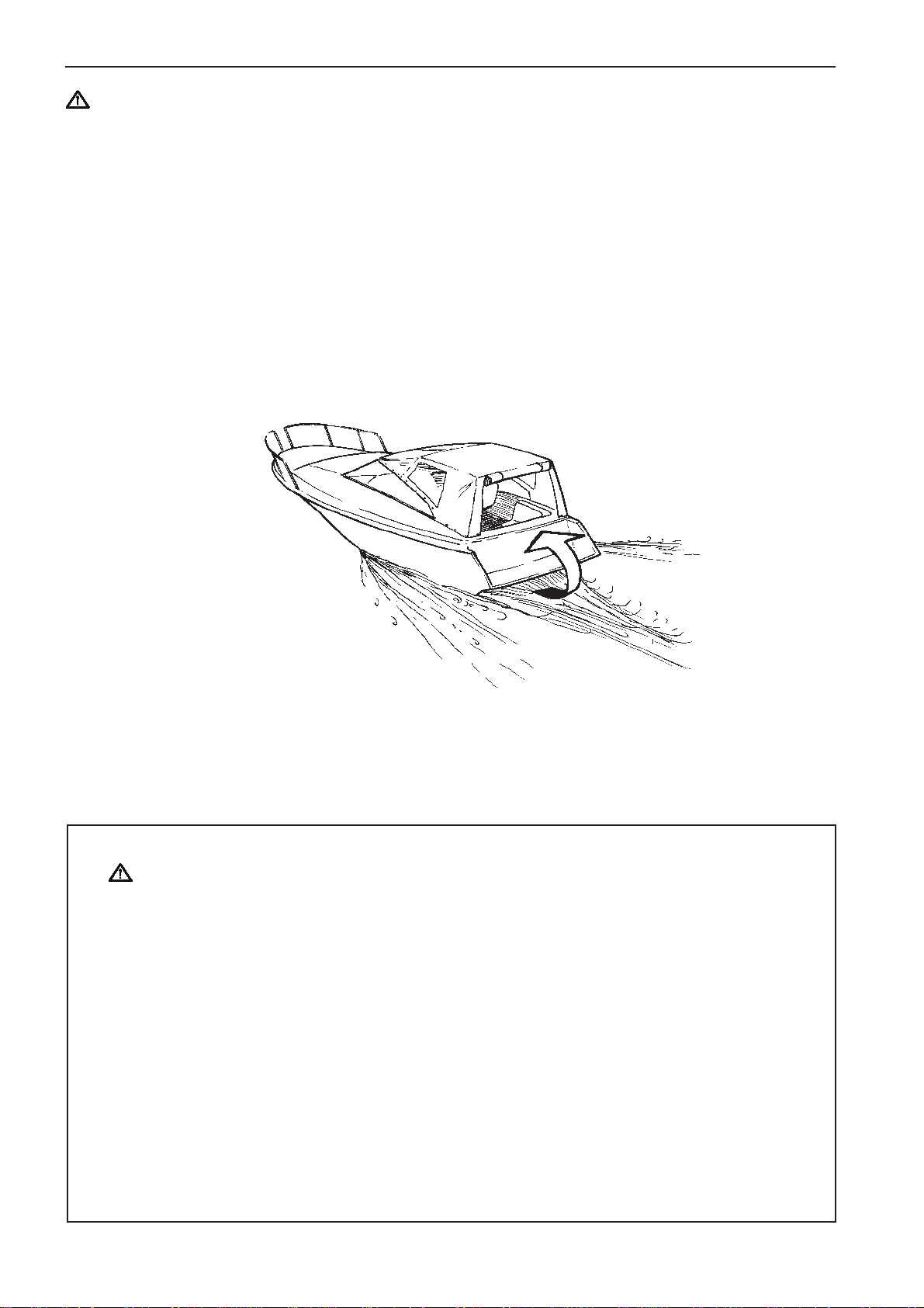
When a boat moves forward through the water a vacuum is created behind it to a greater or lesser extent. In some circumstances this vacuum effect can
be so great that the boat’s own exhaust gases are
sucked into its cockpit or cabin. This poses a risk of
carbon monoxide poisoning to those on-board.
This problem is greatest for high, wide beamed boats
with a vertical stern. However, it can be a problem for
other types of boat in certain conditions (running with
the cover up for example). Other factors that exacer-
bate the problem are wind conditions, load distribution, sea conditions, trim, open hatches and ventilators etc.
Most modern boats are designed so that vacuum effect problems are very rare. If a vacuum forms behind the boat do not open ventilators or hatches at
the front of the boat. Strangely enough this leads to
an increase in the vacuum effect. Instead, try changing speed, trim or load distribution. Try also to take
down, open or in some other way change the configuration of the cover. Contact your boat dealer to
find a solution for your particular boat.
7738812 - Downloaded from www.volvopenta.com 8/2/2009 1:19:46 AM
Remember
● Safety equipment: Life jackets for everybody on board, communication equipment, distress
flares, approved fire extinguishers, life-buoys, anchors, paddles, torches etc.
● Replacement parts and tools: impeller, fuel filter, fuses, tape, hose clamps, engine oil, propeller
and the tools for jobs that may be necessary.
● Get out up-to-date charts for the planned route. Calculate distance and fuel consumption. Listen
to weather reports.
● Tell friends or relatives about your planned route when undertaking longer journeys. Remember
to tell people about changes to your plans.
● Teach those on-board the location of safety equipment and how to use it. Ensure that there is
more than one person on-board who can start and drive the boat safely.
This list should be added to if the type of boat requires extra safety equipment. We recommend that
you contact your local boating organization to find a suitable course.
6

Safety precautions for maintenance and service
Preparations
Knowledge base
The Instruction Manual contains instructions on how
to carry out the commonest maintenance and service
operations safely and correctly. Read them carefully
before starting work.
Service literature for more extensive work can be obtained from your Volvo Penta dealer.
Never undertake an operation if you are not completely sure how to do it. Contact your Volvo Penta
dealer for assistance instead.
Stopping the engine
Stop the engine before the engine compartment cover is opened or removed. Unless otherwise specified all maintenance and service must be carried out
with the engine stopped.
Immobilize the engine by removing the ignition key,
turning off the power supply with the main switch and
locking it in the OFF position. Fix a warning that
work is being undertaken to the control position.
Approaching a running engine is dangerous. Loose
clothing, long hair, fingers or tools can get caught in
rotating parts and cause serious personal injury.
Volvo Penta recommend that all servicing with the
engine running be undertaken by an authorized
Volvo Penta workshop.
Fire and explosion
Fuel and lubricating oil
All fuels, most lubricating oils and many chemicals
pose a fire hazard. Read and follow the instructions
on packaging.
Work on the fuel injection system must be carried out
on a cold engine. A fuel leak or spill onto a hot surface or an electrical component can cause a fire.
Store oil and fuel soaked rags and other flammable
material in fireproof conditions. In certain circumstances oil soaked rags can spontaneously combust.
Never smoke when refueling, changing the oil or close to filling stations or in the engine compartment.
Non-original components
The components in the fuel injection system, ignition
system and electrical system in Volvo Penta products are designed and manufactured to minimize
the risk of fire and explosion.
Using non-original Volvo Penta parts which do not
meet the above standards, can result in fire or explosion on board.
Batteries
Batteries contain and produce oxyhydrogen, especially when they are being charged. This gas is easily
ignited and highly volatile.
Lifting out the engine
Use the lifting eyes mounted on the engine/reverse
gear when lifting the drive unit. Always check that
7738812 - Downloaded from www.volvopenta.com 8/2/2009 1:19:46 AM
lifting equipment is in good condition and has sufficient load capacity to lift the engine (engine weight
including reverse gear and any extra equipment installed). For safety reasons the engine should be lifted with an adjustable lifting beam. All chains and
cables should run parallel to each other and as perpendicular as possible to the top of the engine. Note
that extra equipment mounted on the engine can
change its center of gravity. Special hoists may be
necessary to balance the engine and make handling
it safe. Never carry out work on an engine suspended on a hoist.
Before starting the engine
Reinstall all protective components that have been
removed before starting the engine. Check that no
tools or other objects have been left on the engine.
Never allow a naked flame or sparks near the batteries or battery compartment.
Incorrect connection of a battery lead or jump lead
can cause a spark which is sufficient to cause the
battery to explode.
7

Hot surfaces and liquids
When the engine is at operating temperature there is
always a danger of burns. Avoid hot surfaces. For
example: exhaust manifold, oil sump, hot coolant and
hot lubricating oil in pipes and hoses.
Carbon monoxide poisoning
Only start the engine in a well-ventilated area. If operating the engine in an enclosed space, ensure that
exhaust gases and crankcase emissions are ventilated out of the working area.
Chemicals
Most chemicals such as glycol, rustproofing agents,
inhibiting oils and degreasing agents are hazardous
to health. Read and follow the instructions on packaging.
Certain chemicals such as inhibiting oils are inflammable and also hazardous to health if inhaled. Ensure that ventilation in the workplace is good and use a
protective mask when spraying. Read and follow the
instructions on packaging.
Store chemicals and other hazardous material away
from children. Deposit excess or used chemicals at a
properly designated disposal site.
Cooling system
There is a risk of water penetration when working on
the seawater system. Turn off the engine and close
the sea cock before starting work on the system.
Avoid opening the coolant filler cap when the engine
is hot. Steam or hot coolant can spray out and cause
burns.
7738812 - Downloaded from www.volvopenta.com 8/2/2009 1:19:46 AM
If work must be carried out with the engine at operating temperature and the coolant filler cap or a cock
open or a coolant hose disconnected, open the coolant filler cap carefully and slowly to release pressure
before removing the cap completely. Note that the
coolant may still be hot and can cause burns.
Lubrication system
Hot oil can cause burns. Avoid skin contact with hot
oil. Ensure that the lubrication system is not under
pressure before commencing work on it. Never start
or operate the engine with the oil filler cap removed,
otherwise oil could be ejected.
Fuel system
Always use protective gloves when tracing leaks.
Liquids ejected under pressure can penetrate body
tissue and cause serious injury. There is a danger of
blood poisoning.
Always cover the generator if it is located under the
fuel filter. The generator can be damaged by spilled
fuel.
Electrical system
Cutting off power
Always stop the engine and break the current using
the main switches before working on the electrical
system. Isolate shore current to the engine block
heater, battery charger, or accessories mounted on
the engine.
Batteries
The batteries contain an extremely corrosive electrolyte. Protect your skin and clothes when charging or
handling batteries. Always use protective goggles
and gloves.
If battery electrolyte comes into contact with unprotected skin wash off immediately using plenty of water and soap. If battery acid comes into contact with
the eyes, flush immediately with plenty of water and
obtain medical assistance without delay.
8

Introduction
This Instruction Manual has been compiled to help you get the most from your Volvo Penta engine. It contains
all the information you need in order to operate and maintain your engine safely and correctly. Please read the
Instruction Manual carefully and learn how to operate the engine, controls and other equipment safely.
Always have the Instruction Manual available. Keep it in a safe place and do not forget to give it to the new
owner if you sell your boat.
Responsibility for the environment
We all want to live in a clean environment. Where we
can breathe clean air, see healthy trees, have clean
water in our lakes and oceans and enjoy the sunshine without worrying about our health. Unfortunately
this is no longer something we can take for granted,
we must work hard together for the environment.
As a manufacturer of marine engines Volvo Penta
has a particular responsibility. This is why concern
for the environment is one of the cornerstones of our
product development. Today great advances have
been made in reducing exhaust emissions, fuel consumption and engine noise in Volvo Penta’s wide
range of engines.
We hope that you will take care to maintain these
properties. Always follow the advice in the Instruction
Manual about fuel grades, operation and maintenance and you will avoid unnecessary negative impact
on the environment. If you notice changes such as
increased fuel consumption or exhaust smoke, please contact your Volvo Penta dealer.
Adapt speed and distance so that swell and noise
generated by the boat do not disturb or harm wildlife,
moored boats, landing stages etc. Leave islands and
harbors in the same condition you would like to find
them. Always dispose of environmentally harmful
waste such as engine and transmission oil, coolant,
7738812 - Downloaded from www.volvopenta.com 8/2/2009 1:19:46 AM
old paint, degreasing agents, cleaning residue and
old batteries at proper disposal areas.
Together we can work to make a valuable improvement to the environment.
Check the oil level regularly and more frequently
during the running-in period. The First Service inspection should be carried out after 20 hours of operation.
Fuel and oils
Only use the fuel and oils recommended in the chapter Technical Data. Other grades of fuel and oil can
cause operating problems, increased fuel consumption and, in the long-term, a shorter engine service
life.
Always change oil, oil filters and fuel filters at the recommended intervals.
Service and replacement parts
Volvo Penta engines and are designed for maximum
service life and reliability. They are built to survive in
a tough marine environment, but also to cause as little environmental impact as possible. Regular service
and the use of Volvo Penta Genuine parts will maintain these properties.
Volvo Penta have built up a world wide network of
authorized dealers. They specialize in Volvo Penta
products and can help you to maintain your engine in
top condition. They have the accessories, genuine
replacement parts, test equipment and special tools
necessary to provide high-quality service and repair
work.
Running-in
A new marine engine needs to be run in for its first
20 operating hours. Run the engine at varying engine speeds but at a maximum of 3/4 throttle for the
first two hours. In the next 8 hours of operation use
the same operating method as earlier but with a
maximum of 2 minutes at wide open throttle (WOT)
included. During the last 10 hours the periods of running at WOT can be increased to 5-10 minutes at a
time. Reduce throttle to idle engine speed between
WOT running so that engine temperature drops. Never run an engine at a constant engine speed for
long periods during the running-in period. The engine
can be expected to use more engine oil during the
running-in period than would otherwise be normal.
Always follow the maintenance intervals contained in
the Instruction Manual. Remember to state the engine/transmission identification number when ordering
service and replacement parts.
Certified engines
If you own an engine certificated for Lake Constance
and Switzerland or for any other area where exhaust
emissions are regulated by law,
the following is important:
In some countries and regions environmental legislation requires that the engines in use there be certified.
9
Certification means that an engine type is tested and
approved by the authorities, and that the engine manufacturer guarantees that all engines of that type
manufactured thereafter, correspond to the certified
engine. The manufacturer is also responsible for ensuring that all engines of that type in operation fulfill
the statutory environmental regulations. This places
special requirements on maintenance, service and
replacement parts as follows:
● The maintenance and service intervals recom-
mended by Volvo Penta must be observed.
● Only Volvo Penta genuine replacement parts, in-
tended for the certificated engine, may be used.
● The servicing of ignition, timing and fuel injection
systems (gasoline) or injector pumps, pump settings and injectors (diesel) must always be carried
out be an authorized Volvo Penta workshop.
● The engine must not be modified in any way apart
from with accessories and service kits developed
for it by Volvo Penta.
● No modifications to the exhaust pipes and air
supply ducts for the engine room (ventilation
ducts) may be undertaken as this may effect exhaust emissions.
● Seals may only be broken by authorized person-
nel.
Otherwise the general instructions contained in the
Instruction Manual concerning operation, service and
maintenance must be followed. Always contact your
Volvo Penta dealer if you are not sure about the operation or maintenance of your engine.
IMPORTANT! Use only Volvo Penta Genuine
Parts. Use of non-original AB Volvo Penta spare
parts will result in AB Volvo Penta being unable
to assume liability for the engine meeting engine certification requirements. Any type of damage and/or costs resulting from the use of nonoriginal Volvo Penta replacement parts for the
product will not be covered under any warranty
provided by AB Volvo Penta.
7738812 - Downloaded from www.volvopenta.com 8/2/2009 1:19:46 AM
Warranty
Your new Volvo Penta marine engine is covered by a limited warranty according to the
conditions and instructions contained in the Warranty and Service book.
Note that AB Volvo Penta’s liability is limited to that contained in the Warranty and Service
Book. Read this book as soon as you take delivery of the engine. It contains important
information about warranty cards, service and maintenance which you, the owner, must be
aware of, check and carry out. Liability covered in the warranty may otherwise be refused by
AB Volvo Penta.
* Contact your Volvo Penta dealer if you have not received a Warranty and Service Book.
10
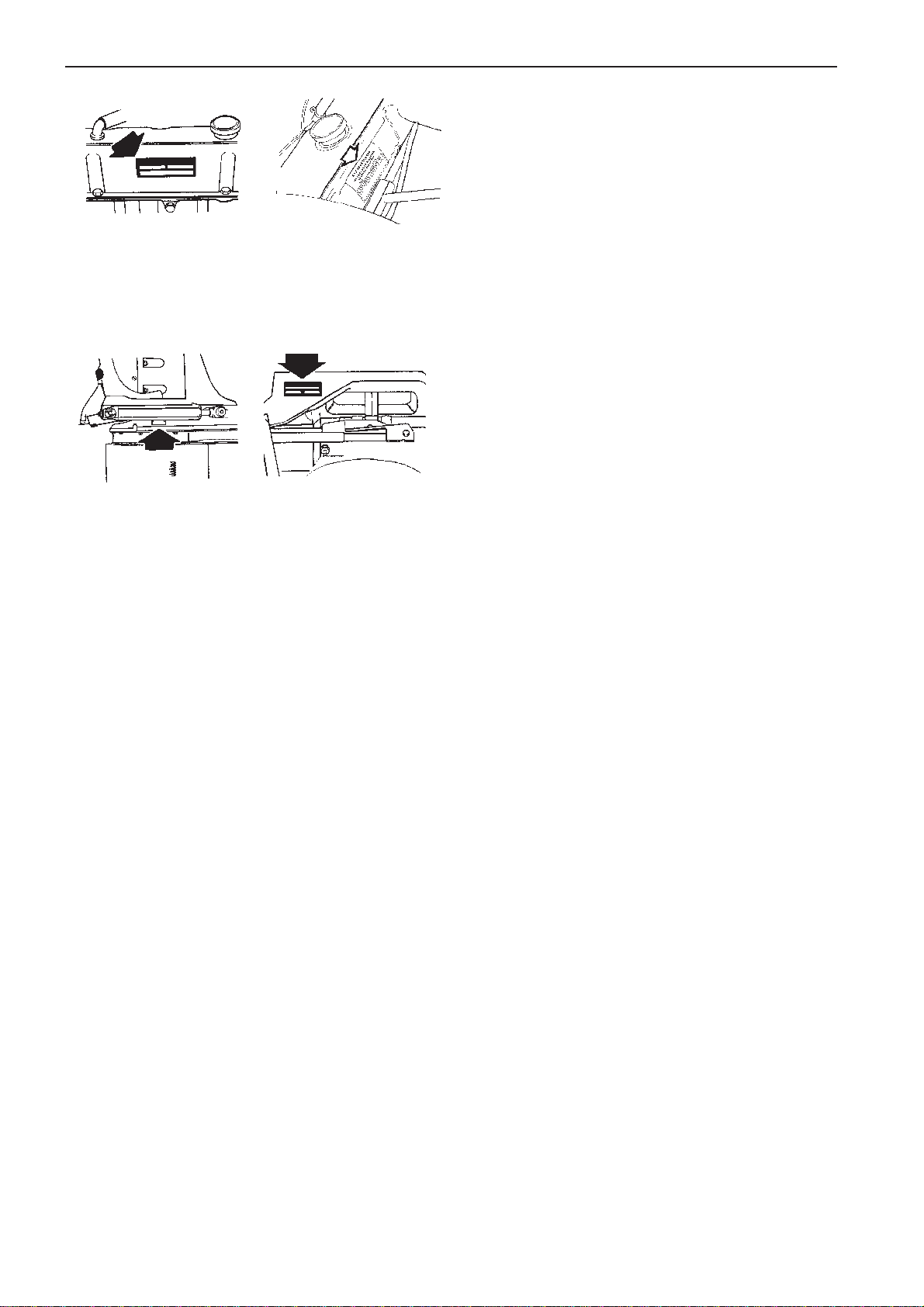
B
Type Approval Number
A type approval number is assigned to an engine
model when it is certified for exhaust emissions.
There are two certification decals placed on the
A
Y
L
N
O
2 1 84 1
L
E
U
14 0
F
D
M
E
O
D
S
A
D
E
L
N
U
engine to verify engine certification; one on the EFI
computer cover, and the other at the front of the port
cylinder head (A). These decals must be maintained
so engine certification can be verified in the future.
When an emissions check is required, the plug (B)
located on the port high-rise elbow can be removed
for installation of a test probe.
7738812 - Downloaded from www.volvopenta.com 8/2/2009 1:19:46 AM
Identification Numbers
Immediately after you have taken delivery of your
boat, make a note of the serial/product number and
model designation of the engine, drive and shield.
Include the serial number and model designation of
the boat and any extra equipment.
This information is necessary when you contact your
Volvo Penta or boat dealer for service and spare
parts. Take a copy of the information and keep it in a
safe place so it is available should the boat be
stolen.
Engine
Product Designation (A) ........................................
Serial Number (B) .................................................
Product Number (C) ..............................................
Drive/Shield
Product Designation (A) ........................................
Serial Number (B) .................................................
Product Number (C) ..............................................
Gear Ratios (D) .....................................................
Propeller designation ............................................
SX/DP-S
Boat
Model/Serial Number ............................................
Extra equipment ....................................................
..............................................................................
..............................................................................
..............................................................................
..............................................................................
11
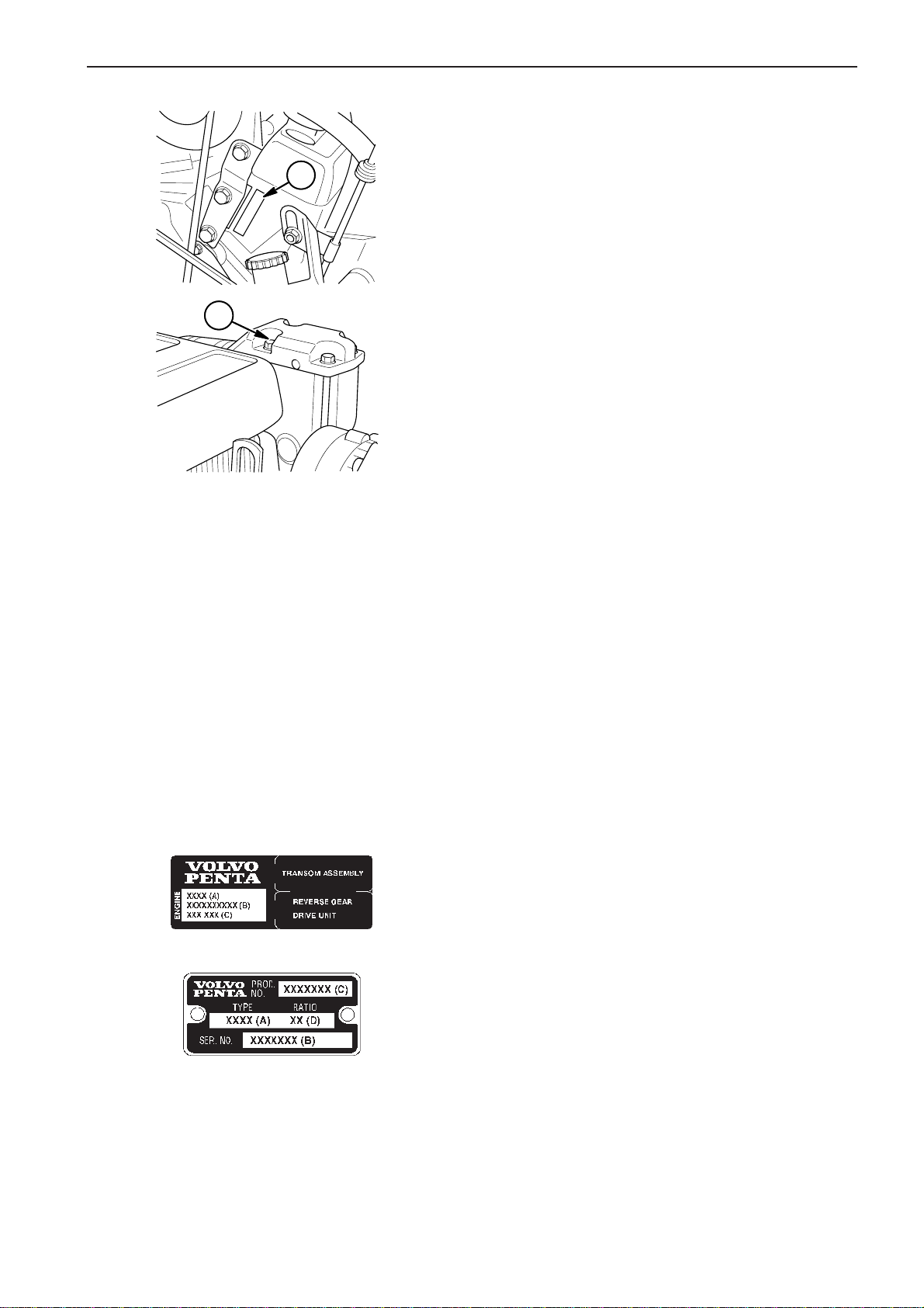
3.0 4.3, 5.0, 5.7
Location of type approval plate, engine type
The engine type approval plate is located on the lefthand valve cover of the engine (3.0 models) and on
the inside of the port valve cover (4.3, 5.0 and 5.7
models).
Location of drive/shield type plate SX/DP-S
The drive type plate is located on the drive unit behind
the port trim/tilt cylinder.
The shield type plate is located on the top of the inner
transom shield.
7738812 - Downloaded from www.volvopenta.com 8/2/2009 1:19:46 AM
12
Presentation
Please note! The photos below do not show all engine/transmission combinations. If your engine does not have
the drive shown, refer to another engine with the relevant drive for an introduction to the transmission.
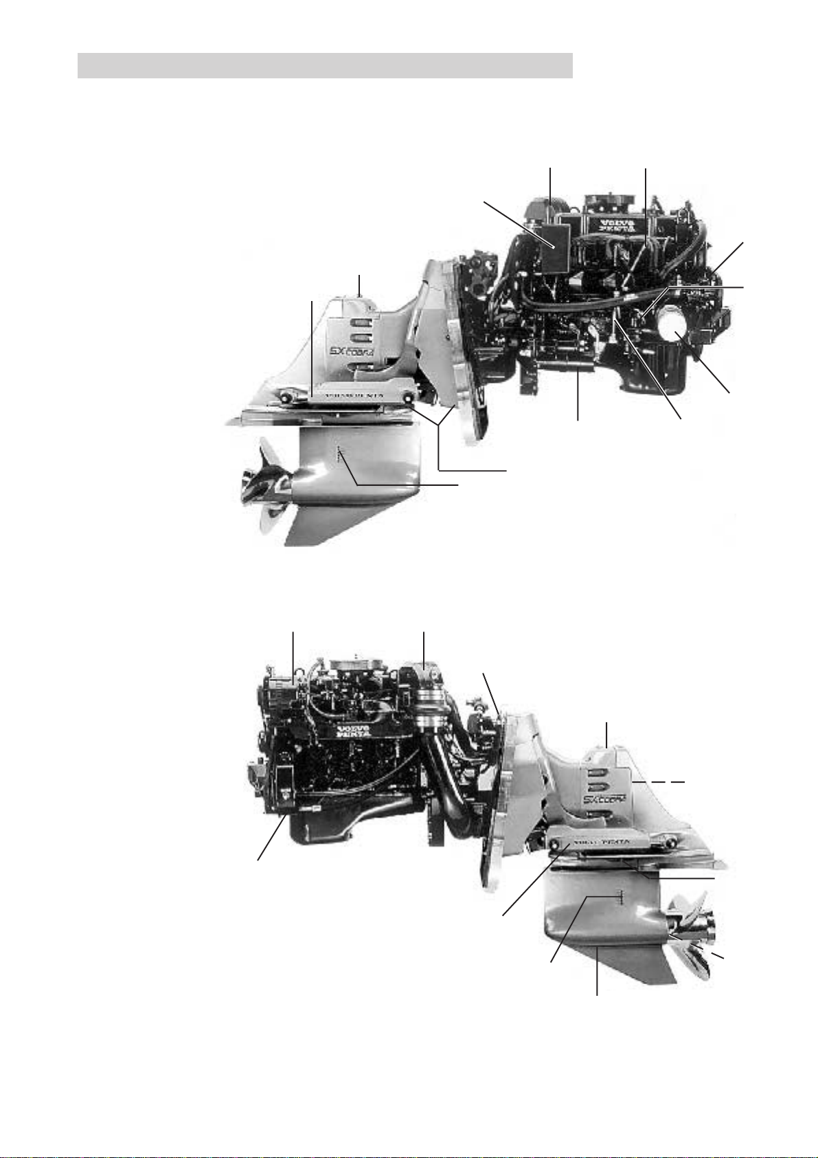
Engine 3.0GS
1. Starter Motor
2. Oil Withdrawal Tube
3. Oil Filter
4. Fuel Pump
5. Oil Level Dipstick
6. Circuit Breakers
7. Type Plate (engine).
See page 12
8. Water-Cooled
Exhaust Pipe
9. Type Plate (shield).
See page 12
10. Seawater Pump
21
19
85
6
10
4
11
3
1
18
17
813
9
SX-C, SX-M Drive
16. Draining Oil
17. Seawater Intake
18. Sacrificial Anodes
19. Oil Level Dipstick
20. Topping Up Oil
21. Trim Cylinder
22. Type Plate
23. Sacrificial Anode,
2
SX-C
7738812 - Downloaded from www.volvopenta.com 8/2/2009 1:19:46 AM
15
11. Fuel Filter
12. Cover for flame arrestor
and carburetor
13. Generator (GEN)
14. Cover for flame arrestor
and throttle housing and
electronic controls
15. Power Steering Pump
21
17
19
20
22
23
16
13
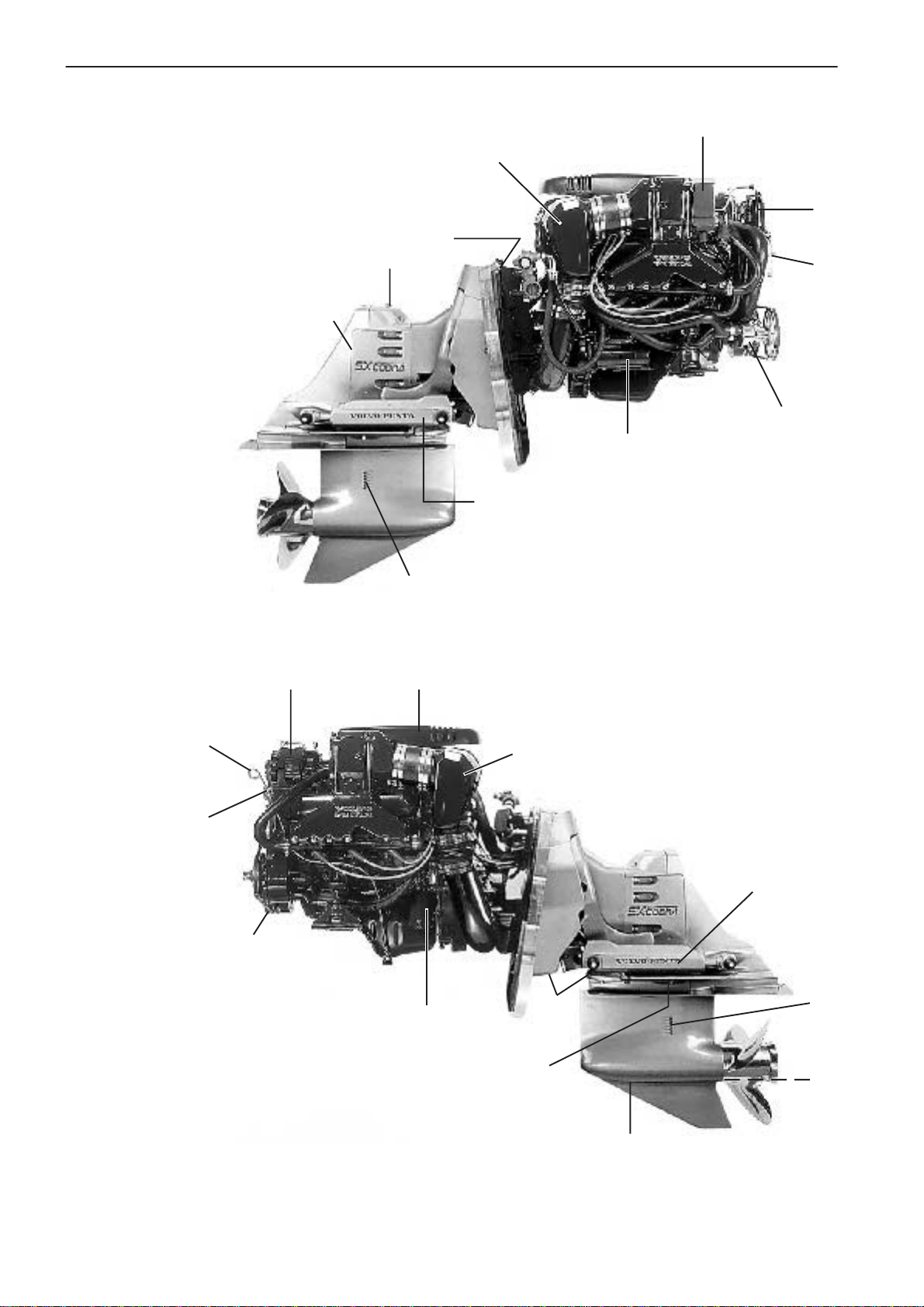
Engine 4.3GL, 4.3GS, 4.3Gi
1. Starter Motor
2. Oil Withdrawal Tube
3. Oil Filter
4. Fuel Pump
5. Oil Level Dipstick
6. Circuit Breakers
7. Type Plate (engine).
See page 12
8. Water-Cooled
Exhaust Pipe
9. Type Plate (shield).
See page 12
10. Seawater Pump
5
20
19
12,1413
17
6
8
4
9
11
10
1
21
SX-C, SX-M Drive
16. Draining Oil
17. Seawater Intake
18. Sacrificial Anodes
19. Oil Level Dipstick
20. Topping Up Oil
21. Trim Cylinder
22. Type Plate
23. Sacrificial Anode,
SX-C
8
7738812 - Downloaded from www.volvopenta.com 8/2/2009 1:19:46 AM
2
15
11. Fuel Filter
12. Cover for flame arrestor
and carburetor
13. Generator (GEN)
14. Cover for flame arrestor
and throttle housing and
electronic controls
15. Power Steering Pump
21
3
18
17
22
23
16
14

Engine 5.0GL, 5.0Gi, 5.7GS, 5.7GSi
1. Starter Motor
2. Oil Withdrawal Tube
3. Oil Filter
4. Fuel Pump
5. Oil Level Dipstick
6. Circuit Breakers
7. Type Plate (engine).
See page 12
8. Water-Cooled
Exhaust Pipe
9. Type Plate (shield).
See page 12
10. Seawater Pump
19
12,14 6
9
4
11
13
5
7738812 - Downloaded from www.volvopenta.com 8/2/2009 1:19:46 AM
2
17
12,14
18
21
1
10
DP-S, DP-SM Drive
16. Draining Oil
17. Seawater Intake
18. Sacrificial Anodes
19. Oil Level Dipstick
20. Topping Up Oil
21. Trim Cylinder
22. Type Plate
8
15
11. Fuel Filter
12. Cover for flame arrestor
and carburetor
13. Generator (GEN)
14. Cover for flame arrestor
and throttle housing and
electronic controls
15. Power Steering Pump
20
21
3
18
22
17
16
15
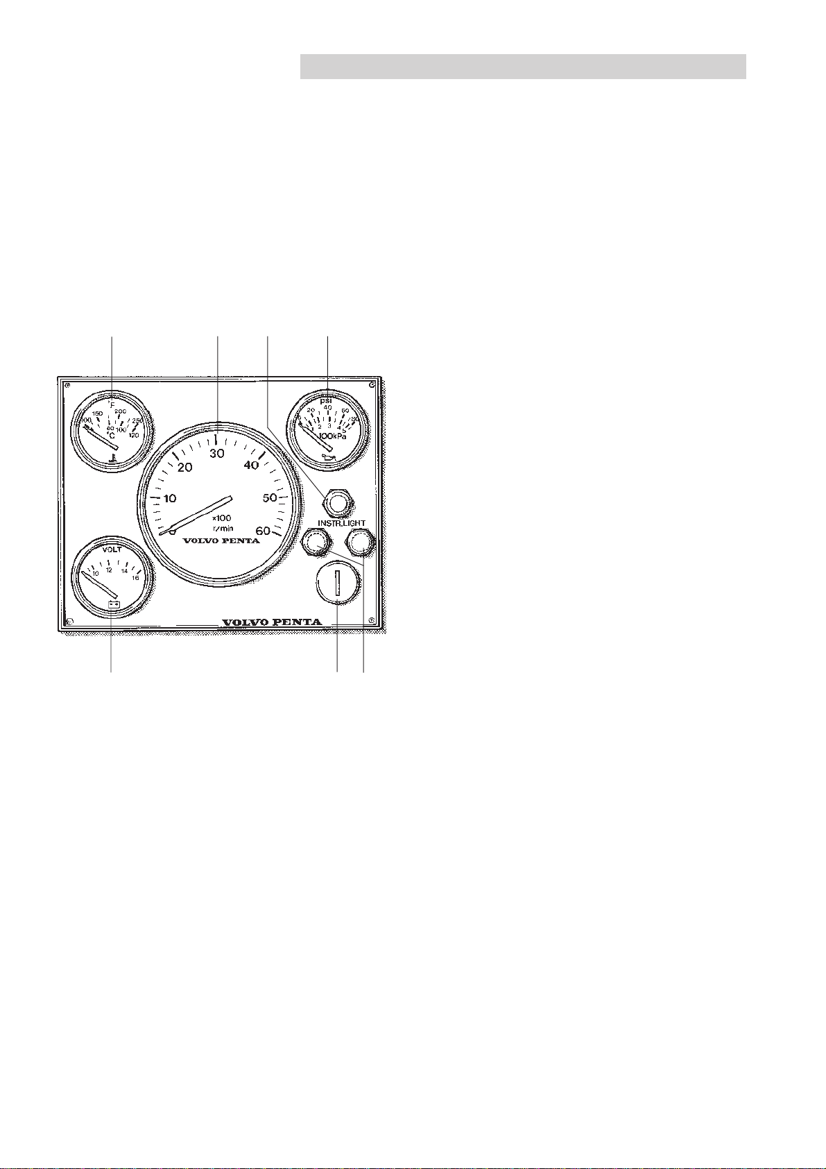
Instrumentation
The instrument panel for Volvo Penta petrol engines is equipped with a tachometer, temperature gauge, oil
pressure gauge, voltmeter, 2 fuses, instrument lighting switch and an ignition switch. Instruments, fuses and
ignition switch can also be installed separately without an instrument panel. The boat builder’s instrumentation
can also be supplemented with extra Volvo Penta instruments, such as: synchronization tachometers, fuel
gauge, fresh water gauge, clock, speed log or rudder indicator.
21531. Tachometer
Shows the rpm of the engine. Multiply this value by
100 for revolutions per minute. Integral "Hours run"
meter (only on separately installed instrument).
Displays the engine’s operating time in hours and
tenths of an hour.
476
7738812 - Downloaded from www.volvopenta.com 8/2/2009 1:19:46 AM
Engine speed range: See chapter
Operation
.
2. Temperature gauge
Indicates the engine coolant temperature. Normal
operating temperature is approx. 70-90°C (158 194°F).
3. Oil pressure gauge
Indicates the oil pressure in the engine. Normal
operating oil pressure is approx. 150-500 kPa (21-71
psi). At engine idle this is normally lower.
4. Voltmeter
Indicates the charge current from the generator
which should normally be approx. 14 V. With the
engine stopped the current indicated is that in the
starter battery circuit, normally 12 V.
5. Instrument lighting
Switch for instrument lighting.
16
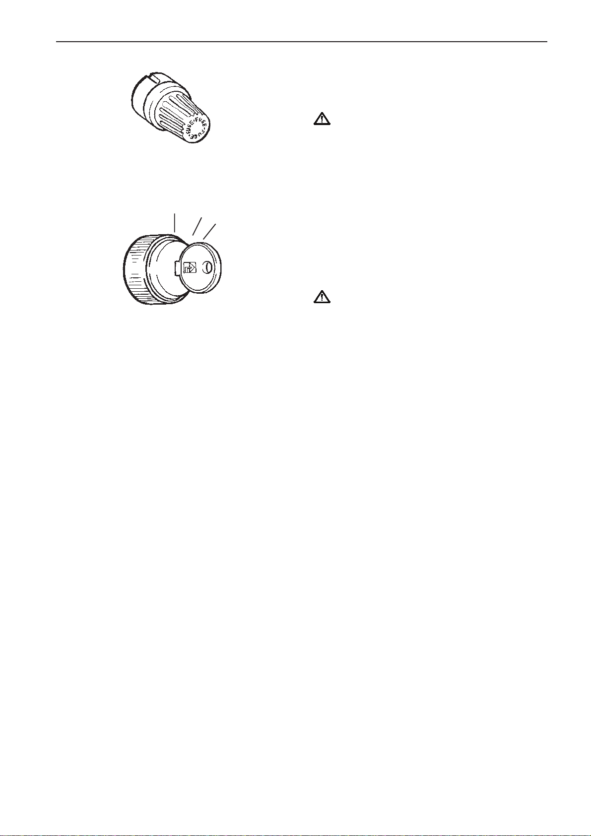
6. Fuses, 8 A
Fuses for the starter function and system voltage. To
change fuses: Press the button and turn anticlockwise.
IMPORTANT Always carry extra fuses on
board.
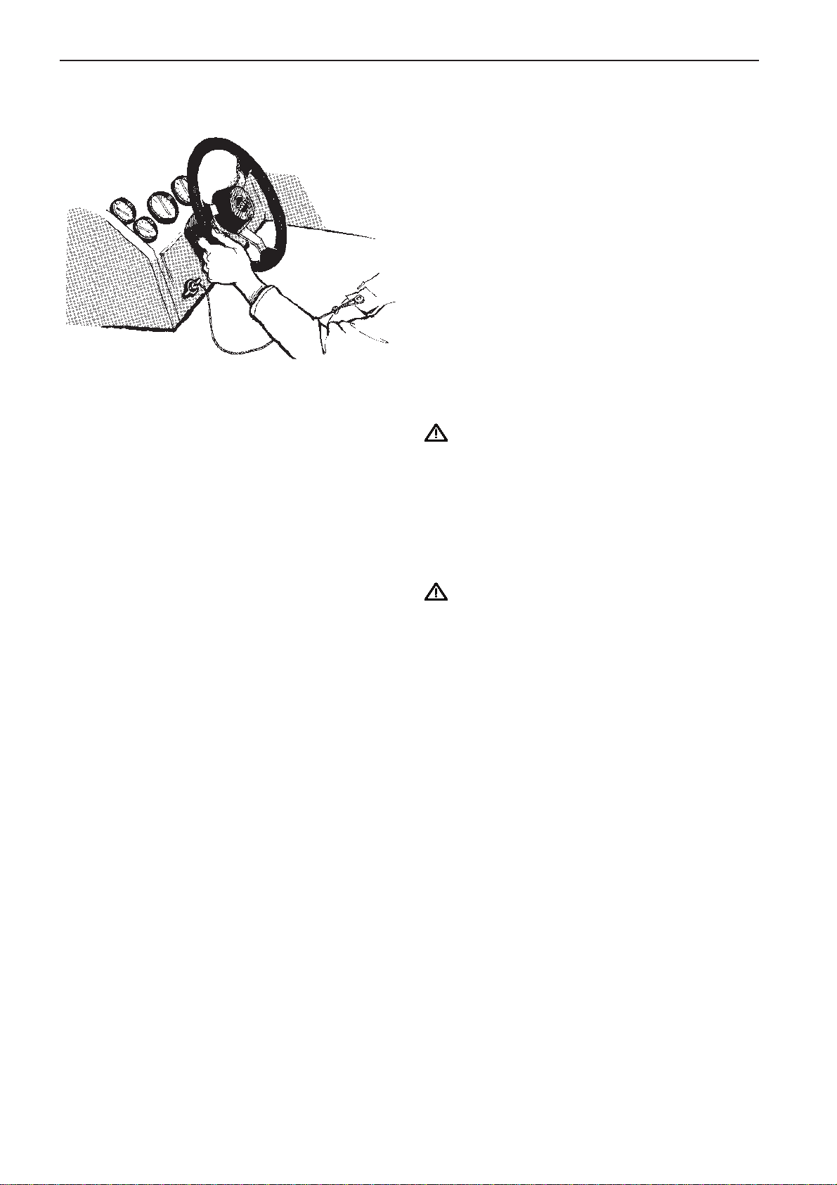
7. Ignition switch
The ignition switch has three positions (these
0
I
II
positions are not marked):
0 = The key can be inserted and taken out.
I = Operating and running position. System voltage
connected
II = Starter position (spring-loaded). The starter
motor is engaged.
IMPORTANT Read the starting instructions in
the chapter
Starting the engine
.
The ignition keys are marked with a key code used
when ordering extra keys. Make a note of this key
code so that keys can be ordered if the old keys get
lost. Keep the code in a safe place where
unauthorized persons do not have access to it.
7738812 - Downloaded from www.volvopenta.com 8/2/2009 1:19:46 AM
17
Emergency stop switch
An emergency stop switch may be a feature of your
boat. Use of this switch is highly recommended. To
properly use this feature, attach the lanyard securely
to your clothing. Do not attach the lanyard to clothing
that will tear away before the lanyard is pulled from
the switch to stop the engine. If the lanyard is too
long, shorten the lanyard by knotting or looping it.
DO NOT cut and retie the lanyard.
Using this switch is simple and should not interfere
with normal operation of the boat. Care must be
taken to avoid accidentally pulling the lanyard during
normal operation. Unexpected loss of forward motion
will occur. This could allow occupants to be thrown
forward. In an emergency situation, any occupant of
the boat can restart the engine. Just press in and
hold the emergency stop switch button, then follow
normal starting procedure. When the button is
released, the engine will stop.
IMPORTANT! The emergency stop switch can
only be effective when in good working condition. Observe the following:
● Lanyard must always be free of
entanglements that could hinder its operation.
● Once a month, check the switch for proper
operation. With engine running, pull lanyard.
If engine does not stop, see your dealer.
7738812 - Downloaded from www.volvopenta.com 8/2/2009 1:19:46 AM
IMPORTANT! If your boat is not equipped with
an emergency stop switch and it falls into one of
the following categories, installation of an emergency stop switch is recommended.
● High performance sport boats
● Small runabouts
● Boats with sensitive steering
● Boats where the distance from the top of the
gunwale down to the driver’s seat is less than
30 cm.
See your Volvo Penta dealer for installation of an
emergency stop switch.
18
Controls
The shift function and engine speed control are combined in one lever. The shift function can be simply
disengaged so that only engine speed is affected. The Volvo Penta controls are available for top or side
mounting. The control levers have an adjustable friction brake. A neutral position switch is available as an
accessory, this will only permit the engine to be started with the drive disengaged.
Your boat may be equipped with remote controls other than those described above. If Volvo Penta controls are
not used, ask your selling dealer for operating instructions for the remote control used in your boat since operation and function may differ from Volvo Penta remote controls.
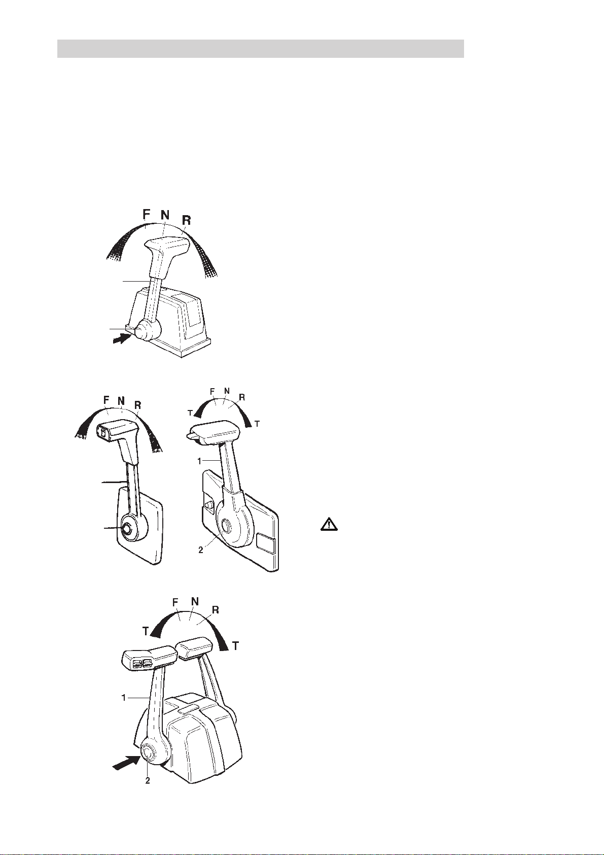
Maneuvering
Shifting and engine speed are controlled with the
same lever (1).
T
1
2
T
T
1
7738812 - Downloaded from www.volvopenta.com 8/2/2009 1:19:46 AM
2
N = Neutral position. Drive/reverse gear disengaged
T
F = Drive/reverse gear engaged for forward movement
(ahead).
R = Drive/reverse gear engaged for backward move-
ment (astern).
T = Engine speed control.
Disengaging the shift function
Move lever (1) to the neutral position (N). Press in
button (2), move the lever slightly forward and release
button. The shift function is now disengaged and the
lever affects only engine speed.
When the lever is moved back to the neutral position
it will automatically re-engage.
IMPORTANT! Take care not to engage the
drive by mistake.
19
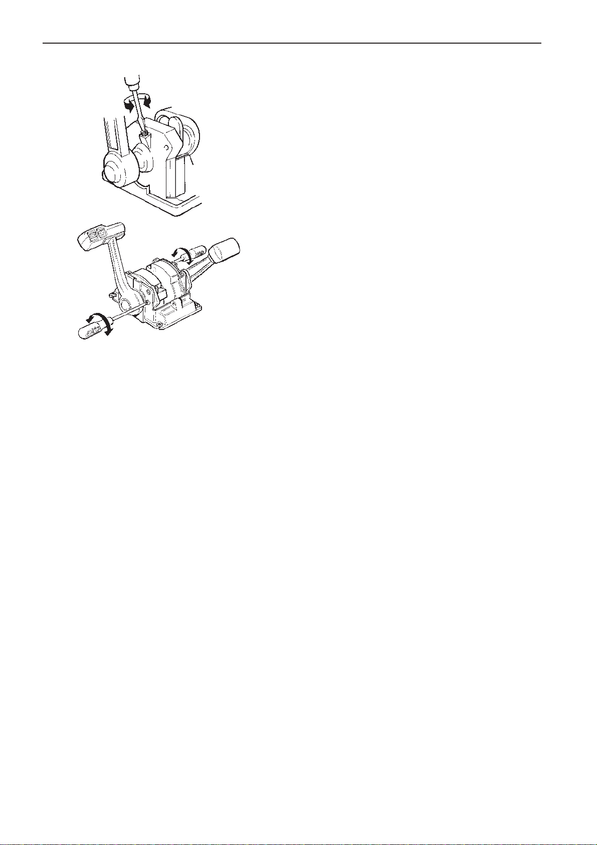
Adjustment of friction brake
The friction brake only affects engine speed adjustment. Adjust with the lever in the throttle half open
position (forward/reverse).
l Remove the cover over the control. For side-
mounted controls the lever must first be
removed.
l Adjust the friction brake by turning the screw at the
arrow (see figure).
l Turn clockwise (+) for more friction and
counterclockwise (-) for less friction.
l Reinstall the cover and lever.
7738812 - Downloaded from www.volvopenta.com 8/2/2009 1:19:46 AM
20
Power T rim
Your Volvo Penta drive has a Power Trim system as standard equipment. The purpose of Power Trim is to allow the helmsman to change the angle at which the drive is set, without leaving the cockpit. Changing this angle
relative to the bottom of the boat is referred to as trimming. Trimming gives the following advantages: Improved
acceleration to planing, keeps the boat planing when the throttles are cut, improves fuel economy, more even
and/or drier running in a choppy sea, increased maximum speed. Some installations also have a trim limiter to
prevent the drive from involuntarily being put into the “Beach” position. The trim limiter is available as an optional accessory for boats with analogue trim gauges. On boats with digital trim gauges, the trim limiter is built into
the gauge. Read more about trimming below and in the
Operation
chapter.
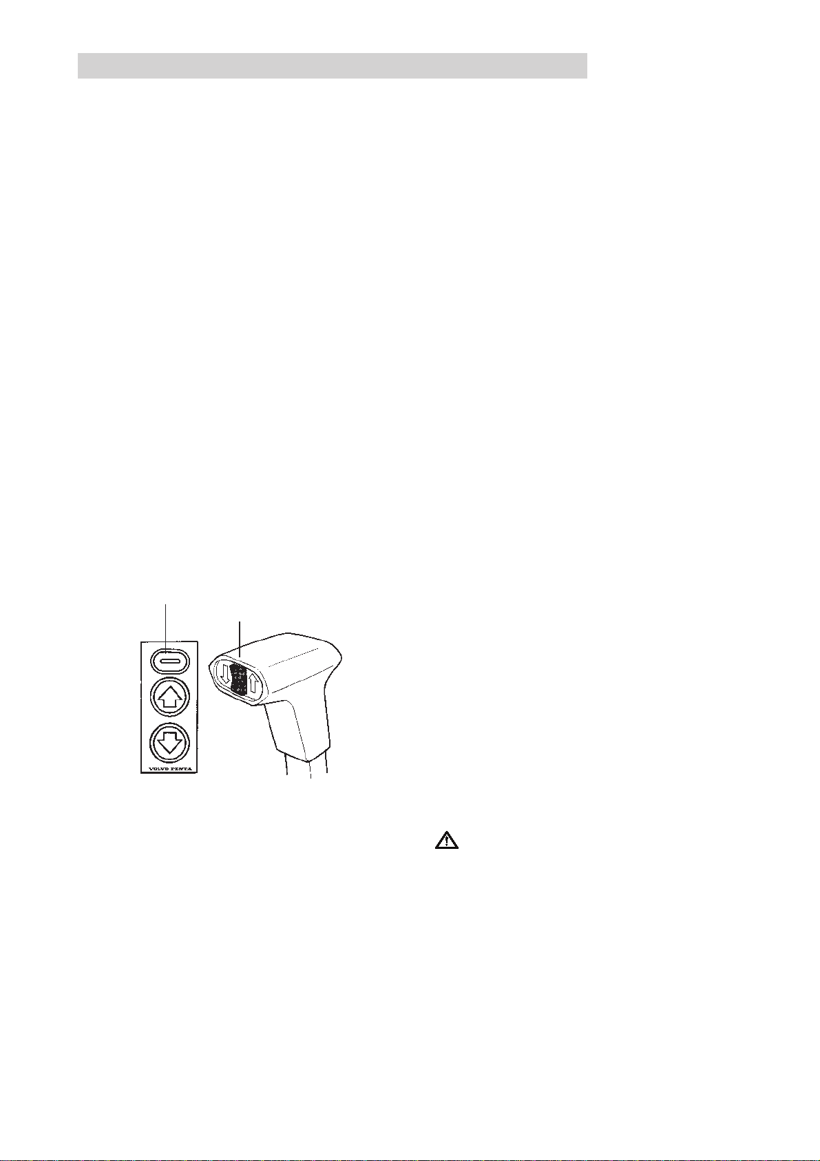
Trim controls
Trimming, i.e. raising and lowering the drive, can
either be done by means of a separate control panel
on the instrument panel, the control button on the
control lever or the control buttons on the port control
lever in a twin installation.
1
2
7738812 - Downloaded from www.volvopenta.com 8/2/2009 1:19:46 AM
The current trim position of the drive is indicated on
a special trim gauge.
Operation
Control panel
The control panel (1) has three buttons. The centre
button moves the drive trim out, and the bow of the
boat is raised. Using the lower button, the drive is
trimmed in, and the bow is lowered.
The top button is used to disconnect a “catch” for the
“Beach” position, so that the drive can be trimmed
into this position. The button should be pressed at
the same time as the centre button.
Note! The catch button does not have any function if
the drive does not have a trim limiter.Please refer to
Trim instrument,
IMPORTANT! The drives must be operated wit-
hin the trim range limits, –2° — +5°. When operating outside of trim range the engine speed
must be reduced to 1000 rpm.
and the
Operation
chapter.
21
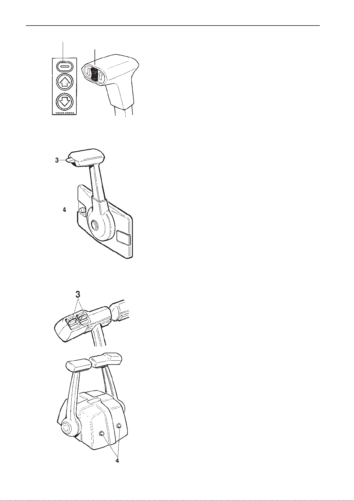
1
2
Control lever
Control button (2) in the control lever is used to raise
the bow, by pressing the top half, and to lower the
bow by pressing the lower half of the button.
To put the drive in the “Beach” position, you have to
press a separate switch to bypass the catch which
prevents entry to the “Beach” area. This switch is on
the instrument panel.
Note! The switch does not have any function if the
drive does not have a trim limiter.
Control with catch button
There is a tumbler switch (3) on the control lever to
trim the drive. By pressing the tumbler switch upwards, the drive is trimmed out and the bow is raised. When the switch is pressed down, the drive is
trimmed in and the bow is lowered. Button (4) is used
to bypass the catch which prevents entry to the “Beach” area.
7738812 - Downloaded from www.volvopenta.com 8/2/2009 1:19:46 AM
Note! The catch button does not have any function if
the drive does not have a trim limiter.
Controls with catch button, twin installation
There are two tumbler switches (3) on the port control lever for individual adjustment of drive trim. By
pressing the tumbler switches upwards, the drives
are trimmed out and the bow is raised. When the
switches are pressed down, the drives are trimmed
in and the bow is lowered. Buttons (4) are used to
bypass the catch which prevents entry to the “Beach” area for each drive and make it possible to adjust the trim in this area.
Note! The catch button does not have any function if
the drive does not have a trim limiter.
22
Trim instruments
The SX drive only has an analogue trim instrument.
The DP-S drive can either have an analogue or digi-
tal trim instrument.
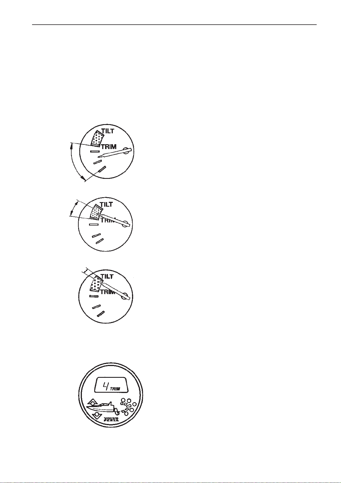
Analogue trim instrument (SX, DP-S)
The trim instrument indicates the current trim position.
It has a scale with five segments and three main
ranges:
1. Trim range
The trim range is used to achieve maximum comfort
under normal operation from start to maximum
speed.
7738812 - Downloaded from www.volvopenta.com 8/2/2009 1:19:46 AM
2. Beach range
The beach range is used for operation at reduced
speed (max. 1000 rpm) in shallow water where water
depth is uncertain. This range is also used when
launching and taking the boat out of the water onto a
trailer ramp.
3. Lift range
The lift range is used for lifting the drive to its maximum angle, however this cannot be used during
operation. This range is used for transporting the
boat and to minimize fouling of the drive. The Power
Trim has an automatic stop which cuts off the current
when the stop position is reached. The stop is automatically reset when trimming down.
Digital trim instrument (DP-S)
Displays a figure within the range. This figure is the
angle of the drive to perpendicular (stationary boat).
The instrument has a built in control program which
starts each time the instrumentation is switched on
with the ignition key. When this control program is
run, all LCD segments light and A- BEACH is
displayed. The instrument then returns to displaying
the current drive angle.
23
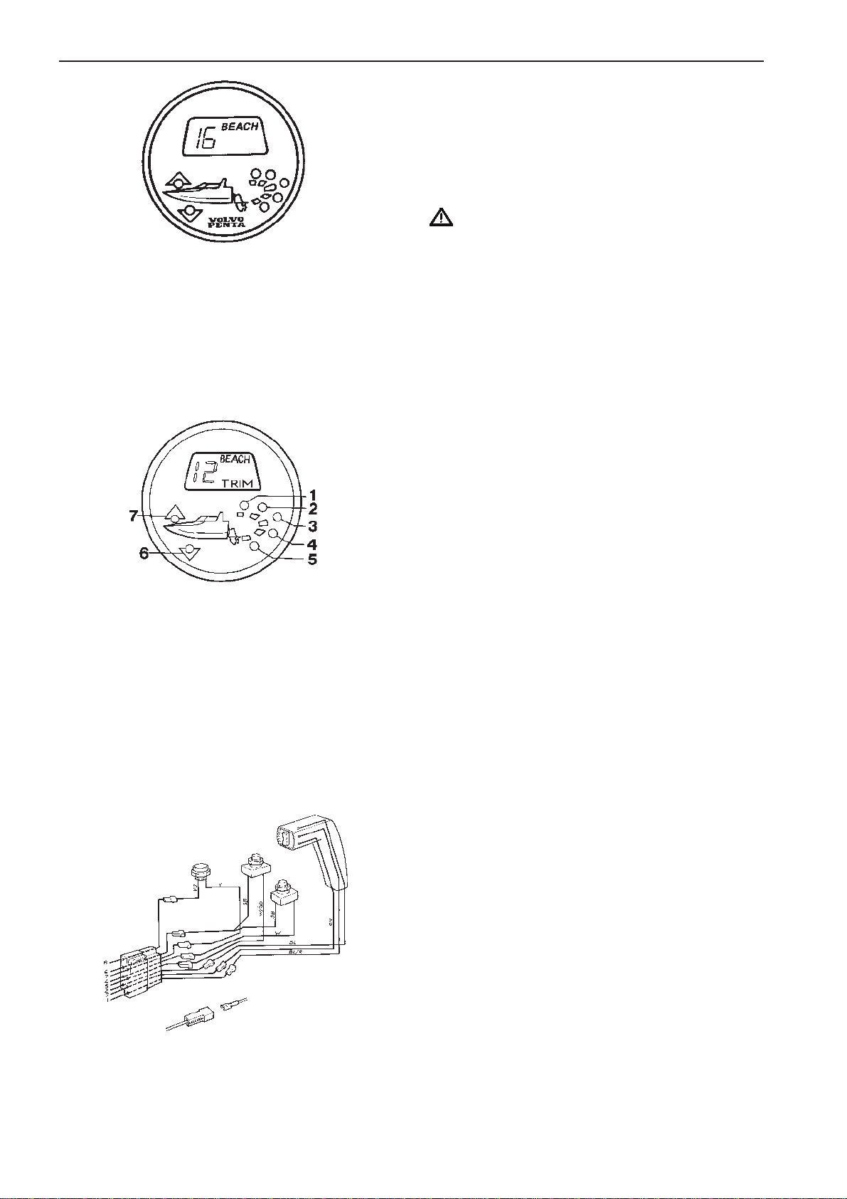
TRIM = Drive position at all speeds. Max trim up to 5.
BEACH = Used for operation at in shallow water
where water depth is uncertain. Speed should always
be low, max. 1000 rpm. 5 - 40.
LIFT = Flashing red warning lamp. Drive up completely
41 - 51. See LEDs position 1.
IMPORTANT! The engine must not be run with
the drive in this position.
LEDs
1 Flashes red within the lift range above 41. Other-
wise out.
2 Constant red light: 6 - 40. Otherwise out.
3 Constant green light: 2 - 5. Otherwise out.
4 Constant green light in the range 0 - 2. Otherwise
out.
7738812 - Downloaded from www.volvopenta.com 8/2/2009 1:19:46 AM
5 Constant green light in trimmed range up to 0.
Otherwise out.
6 Constant yellow light in maximum trimmed posi-
tion up to 0. Flashes when above 0. The drive
moves and the bow is lowered. Otherwise out.
7 Constant yellow light. 2 - 5. Flashes when the
drive moves within trimrange and the bow is raised.
BEACH hold function
Boats with digital trim instruments and separate switches for bypassing the catch which prevents entry to
the “Beach” area can be equipped with a further
switch with warning lamp, a so-called hold function
(optional). Trimming to and inside the “Beach” area is
done as follows:
Press the button to activate the hold function. At the
same time, trim the drive into the “Beach” area. The
indication lamp is now lit, to indicate that the bypass
hold function is now in action. The drives can now be
trimmed in the “Beach” area by a one-hand operation, by just pressing the trim adjustment buttons.
The hold function is retained for as long as the drives
remain in the “Beach” area. When the drive is lowered and the drive re-enters the “Trim” area, the catch
which prevents entry to the “Beach” area is re-activated and the indication lamp goes out.
24
Trim/tilt motor protection
IMPORTANT! Always allow the trim/tilt switch to
return to its center position when the drive unit
reaches the maximum raised or lowered position.
This will prevent your trim/tilt motor from overheating.
The trim/tilt motor is protected from overheating by an
internal thermal overload switch. Should the electric
motor stop while tilting, release the switch and allow
the overload switch to cool and automatically reset itself. When the overload switch has reset, tilting may
be resumed. Make sure the drive unit is not being restrained, causing the motor to overheat. If the trim motor still does not function, check the circuit breaker on
the pump/pump bracket (10 A), the inline fuse (5A) in
the Power Trim switch cabling (if mounted). Also
check the circuit breaker on the fuse box (50 A). Please refer to
Electric system
for more information.
7738812 - Downloaded from www.volvopenta.com 8/2/2009 1:19:46 AM
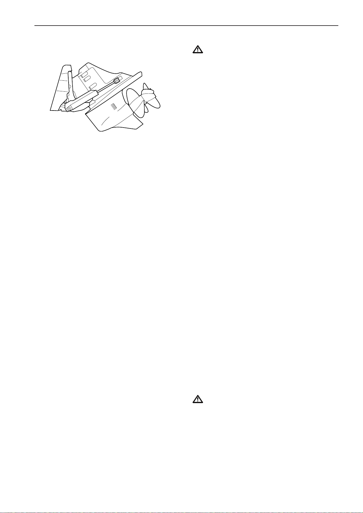
Impact protection
The trim/tilt system provides impact protection for the
drive unit. Still, impact damage can occur in either
forward or reverse directions. Care must be taken:
l When operating in forward or reverse
l When backing at low speed
l When trailering boat
l When launching boat
Impact damage is more likely to occur when in a turn
where side loads are placed on the drive unit.
If the drive unit strikes a solid object, throttle back
and shut off engine immediately. Closely inspect the
boat and drive unit for damage, particularly the
transom shield assembly that contains steering
system components. Check engine compartment for
water leakage.
If there is obvious or suspected damage, operate boat
at low RPM and take your boat to a Volvo Penta
dealer for inspection. Have necessary repairs made
immediately. Operating a damaged drive unit could
cause additional damage and could become very
costly to repair.
IMPORTANT! Failure to inspect for damage
may:
l Result in sudden loss of steering control.
l Adversely affect your boat and drive unit’s
ability to resist subsequent high speed
impacts.
NOTE! When moving in reverse there is no impact
protection. Use caution when moving in reverse.
Do not exceed 2500 RPM.
25
 Loading...