

Volvo Penta 230, 250, AQ171, 251DOHC, AQ131 Workshop Manual
...
Engine
230, 250, 251DOHC
AQ131, AQ151, AQ171
Workshop Manual
2(0)
C


1
Safety Precautions .............................................................................. 2
General information............................................................................ 5
Repair instructions ............................................................................. 6
Presentation ........................................................................................ 8
Trouble-shooting Scheme ..................................................................11
1. Overhaul Data...............................................................................12
2. Special Tools ................................................................................20
3. Electrical System .........................................................................23
Wiring Diagram AQ131, AQ151, 230, 250 Alt. 1.........................24
Wiring Diagram 230, 250 Alt. 2..................................................26
Wiring Diagram AQ171, 251DOHC Alt.1. ..................................28
Wiring Diagram 251DOHC Alt. 2 ............................................... 30
4A. Fuel System ..................................................................................3 2
Trouble shooting and Remedies Fuel System ............................32
Overhauling and checking the carburetor...................................33
4B. Renix Ignition System..................................................................38
Trouble-shooting and repair ignition system 251DOHC, AQ171 38
4C. Cylinder Head ...............................................................................44
Removal of teh external components ......................................... 44
4D. Cooling System ............................................................................48
Overhauling the heat exchanger .................................................48
Overhauling the sea water pump ................................................49
Check the thermostat .................................................................. 49
4E. Overhauling the valve system .....................................................50
Overhauling the valve system 230, 250, AQ131, AQ151 ........... 50
Adjusting the valves 230, 250, AQ131, AQ151.......................... 59
Valve system 251DOHC, AQ171. Technical Description...........61
Overhauling the valve system 251DOHC, AQ171......................63
4F. Installing the toothed belt ...........................................................71
Installing the toothed belt 230, 250, AQ131, AQ151 ......................71
Installing the toothed belt 251DOHC, AQ171.................................73
4G. Installing the external components of the Cylinder Head ........74
5. Cylinder Block ..............................................................................78
5A. Removing the external components...........................................78
5B. Overhauling the Crank Assembly ...............................................80
The lubricating oil pump Overhauling..........................................87
5C. Installing the external components ............................................93
Overhauling the oil cooler 250, 251DOHC, AQ151, AQ171........95
Workshop Manual
Index
230, 250, 251DOHC,
AQ131, AQ151, AQ171

2
Safety Precautions
Check that the warning or information decals on
the product are always clearly visible. Replace
decals that have been damaged or painted over.
Engine with turbocharger: Never start the engine
without installing the air cleaner (ACL). The rotating compressor in the Turbo can cause serious personal injury. Foreign objects entering
the intake ducts can also cause mechanical
damage.
Never use start spray or similar to start the engine. The starter element may cause an explosion in the inlet manifold. Danger of personal injury.
Avoid opening the filler cap for engine coolant
system (freshwater cooled engines) when the
engine is still hot. Steam or hot coolant can
spray out. Open the coolant filler cap carefully
and slowly to release pressure before removing
the cap completely. Take great care if a cock,
plug or engine coolant line must be removed
from a hot engine. It is difficult to anticipate in
which direction steam or hot coolant can spray
out.
Hot oil can cause burns. Avoid skin contact with
hot oil. Ensure that the lubrication system is not
under pressure before commencing work on it.
Never start or operate the engine with the oil
filler cap removed, otherwise oil could be
ejected.
Stop the engine and close the sea cock before
carrying out operations on the engine cooling
system.
Only start the engine in a well-ventilated area. If
operating the engine in an enclosed space, ensure that exhaust gases and crankcase ventilation emissions are ventilated out of the working
area.
Introduction
This Workshop Manual contains technical data, descriptions and repair instructions for Volvo Penta products or product versions contained in the contents list.
Ensure that the correct workshop literature is being
used.
Read the safety information and the Workshop
Manual “General Information” and “Repair Instructions” carefully before starting work.
Important
In this book and on the engine you will find the following special warning symbols.
WARNING! If these instructions are not followed there is a danger of personal injury, extensive damage to the product or serious mechanical malfunction.
IMPORTANT! Used to draw your attention to
something that can cause damage, product
malfunction or damage to property.
NOTE! Used to draw your attention to important in-
formation that will facilitate work or operations.
Below is a summary of the risks and safety precautions you should always observe or carry out when
operating or servicing the engine.
Immobilize the engine by turning off the power
supply to the engine at the main switch (switches) and lock it (them) in the OFF position before
starting work. Set up a warning notice at the engine control point or helm.
Generally, all servicing should be carried out
with the engine switched off. Some work (carrying out certain adjustments for example) requires the engine to be running. Approaching a
running engine is dangerous. Loose clothing or
long hair can fasten in rotating parts and cause
serious personal injury. If working in proximity
to a running engine, careless movements or a
dropped tool can result in personal injury. Avoid
burns. Take precautions to avoid hot surfaces
(exhausts, turbochargers, charge air pipes and
starter elements etc.) and liquids in supply lines
and hoses when the engine is running or has
been turned off immediately prior to starting
work on it. Reinstall all protective parts removed
during service operations before starting the engine.

3
Always use protective goggles where there is
a danger of pieces of metal, sparks from grinding, acid or other chemicals being thrown into
your eyes. Your eyes are very sensitive, injury
can lead to loss of sight!
Avoid skin contact with oil. Long-term or repeated contact with oil can remove the natural
oils from your skin. The result can be irritation,
dry skin, eczema and other skin problems.
Used oil is more dangerous to health than new
oil. Use protective gloves and avoid using oilsoaked clothes and rags. Wash regularly, especially before meals. Use the correct barrier
cream to prevent dry skin and to make cleaning your skin easier.
Most chemicals used in products (engine and
transmission oils, glycol, petrol and diesel oil)
and workshop chemicals (solvents and paints)
are hazardous to health Read the instructions
on the product packaging carefully! Always follow safety instructions (using breathing apparatus, protective goggles and gloves for example). Ensure that other personnel are not
unwittingly exposed to hazardous substances
(by breathing them in for example). Ensure
that ventilation is good. Handle used and excess chemicals according to instructions.
Be extremely careful when tracing leaks in the
fuel system and testing fuel injection nozzles.
Use protective goggles! The jet ejected from a
fuel injection nozzle is under very high pressure, it can penetrate body tissue and cause
serious injury There is a danger of blood poisoning.
All fuels and many chemicals are inflammable.
Ensure that a naked flame or sparks cannot ignite fuel or chemicals. Combined with air in
certain ratios, petrol, some solvents and hydrogen from batteries are easily inflammable
and explosive. Smoking is prohibited! Ensure
that ventilation is good and that the necessary
safety precautions have been taken before
carrying out welding or grinding work. Always
have a fire extinguisher to hand in the workplace.
Store oil and fuel-soaked rags and fuel and oil
filters safely. In certain conditions oil-soaked
rags can spontaneously ignite. Used fuel and
oil filters are environmentally dangerous waste
and must be deposited at an approved site for
destruction together with used lubricating oil,
contaminated fuel, paint remnants, solvent, degreasing agents and waste from washing
parts.
Never allow a naked flame or electric sparks
near the batteries. Never smoke in proximity to
the batteries. The batteries give off hydrogen
gas during charging which when mixed with air
can form an explosive gas – oxyhydrogen.
This gas is easily ignited and highly volatile.
Incorrect connection of the battery can cause
a spark which is sufficient to cause an explosion with resulting damage. Do not disturb battery connections when starting the engine
(spark risk) and do not lean over batteries.
Never mix up the positive and negative battery
terminals when installing. Incorrect installation
can result in serious damage to electrical
equipment. Refer to wiring diagrams.
Always use protective goggles when charging
and handling batteries. The battery electrolyte
contains extremely corrosive sulfuric acid. If
this comes into contact with the skin, wash immediately with soap and plenty of water. If battery acid comes into contact with the eyes, immediately flush with copious amounts of water
and obtain medical assistance.
Turn off the engine and turn off power at main
switch(es) before carrying out work on the
electrical system.
Clutch adjustments must be carried out with
the engine turned off.

4
Use the lifting eyes mounted on the engine/reverse gear when lifting the drive unit.
Always check that lifting equipment is in good
condition and has sufficient load capacity to lift
the engine (engine weight including reverse
gear and any extra equipment installed).
To ensure safe handling and to avoid damaging
engine components on top of the engine, use a
lifting beam to raise the engine. All chains and
cables should run parallel to each other and as
perpendicular as possible in relation to the top
of the engine.
If extra equipment is installed on the engine altering its center of gravity, a special lifting device is required to achieve the correct balance
for safe handling.
Never carry out work on an engine suspended
on a hoist.
Never remove heavy components alone, even
where secure lifting equipment such as secured blocks are being used. Even where lifting equipment is being used it is best to carry
out the work with two people; one to operate
the lifting equipment and the other to ensure
that components are not trapped and damaged
when being lifted. When working on-board ensure that there is sufficient space to remove
components without danger of injury or damage.
Components in the electrical system, ignition
system (gasoline engines) and fuel system on
Volvo Penta products are designed and constructed to minimize the risk of fire and explosion. The engine must not be run in areas
where there are explosive materials.
Always use fuels recommended by Volvo Penta. Refer to the Instruction Book. The use of
lower quality fuels can damage the engine. On
a diesel engine poor quality fuel can cause the
control rod to seize and the engine to overrev
with the resulting risk of damage to the engine
and personal injury. Poor fuel quality can also
lead to higher maintenance costs.

5
General information
About the workshop manual
This workshop manual contains technical specification, descriptions and instructions for repairing the
standard versions of the following engines 230, 250,
251DOHC, AQ131, A Q151 and A Q171. The product
designation and number should be given in all correspondence about the product.
This Workshop Manual has been developed primarily
for Volvo Penta service workshops and qualified personnel. Persons using this book are assumed to
have a grounding in marine drive systems and be
able to carry out related mechanical and electrical
work.
Volvo Penta is continuously developing their products. We therefore reserve the right to make
changes. All the information contained in this book is
based on product data available at the time of going
to print. Any essential changes or modifications introduced into production or updated or revised service methods introduced after the date of publication
will be provided in the form of Service Bulletins.
Replacement parts
Replacement parts for electrical and fuel systems
are subject to statutory requirements (US Coast
Guard Safety Regulations for example). Volvo Penta
Genuine parts meet these requirements. Any type of
damage which results from the use of non-original
Volvo Penta replacement parts for the product will
not be covered under any warranty provided by Volvo Penta.

6
Repair instructions
The working methods described in the Service Manual apply to work carried out in a workshop. The
engine has been removed from the boat and is installed in an engine fixture. Unless otherwise stated
reconditioning work which can be carried out with
the engine in place follows the same working
method.
Warning symbols occurring in the Workshop Manual
(for their meaning see
Safety information
)
WARNING!
IMPORTANT!
NOTE!
are not in any way comprehensive since it is impossible to predict every circumstance under which service work or repairs may be carried out. For this reason we can only highlight the risks that can arise
when work is carried out incorrectly in a wellequipped workshop using working methods and
tools developed by us.
All procedures for which there are Volvo Penta special tools in this Workshop Manual are carried out
using these. Special tools are developed to rationalize working methods and make procedures as safe
as possible. It is therefore the responsibility of any
person using tools or working methods other than
the ones recommended by us to ensure that there is
no danger of injury, damage or malfunction resulting
from these.
In some cases there may be special safety precautions and instructions for the use of tools and chemicals contained in this Workshop Manual. These special instructions should always be followed if there
are no separate instructions in the Workshop Manual.
Certain elementary precautions and common sense
can prevent most risks arising. A clean workplace
and engine eliminates much of the danger of injury
and malfunction.
It is of the greatest importance that no dirt or foreign
particles get into the fuel system, lubrication system, intake system, turbocharger, bearings and
seals when they are being worked on. The result
can be malfunction or a shorter operational life.
Our joint responsibility
Each engine consists of many connected systems
and components. If a component deviates from its
technical specification the environmental impact of an
otherwise good engine may be increased significantly.
It is therefore vital that wear tolerances are maintained, that systems that can be adjusted are adjusted
properly and that Volvo Penta Genuine Parts as used.
The engine Maintenance Schedule must be followed.
Some systems, such as the components in the fuel
system, require special expertise and special testing
equipment for service and maintenance. Some components are sealed at the factory for environmental
reasons. No work should be carried out on sealed
components except by authorized personnel.
Bear in mind that most chemicals used on boats are
harmful to the environment if used incorrectly.
Volvo Penta recommends the use of biodegradable
degreasing agents for cleaning engine components,
unless otherwise stated in a workshop manual. Take
special care when working on-board, that oil and
waste is taken for destruction and is not accidentally
pumped into the environment with bilge water.
Tightening torques
Tightening torques for vital joints that must be
tightened with a torque wrench are listed in workshop
manual “Technical Data”: “Tightening Torques” and are
contained in work descriptions in this Manual. All torques apply for cleaned threads, screw heads and
mating surfaces. Torques apply for lightly oiled or dry
threads. If lubricants, locking fluid or sealing compound are required for a screwed joint this information
will be contained in the work description and in “Tightening Torques” Where no tightening torque is stated for
a joint use the general tightening torques according to
the tables below. The tightening torques stated are a
guide and the joint does not have to be tightened using
a torque wrench.
Dimension Tightening T orques
Nm lbt.ft
M5 6 4,4
M6 10 7,4
M8 25 18,4
M10 50 36,9
M12 80 59,0
M14 140 103,3

7
Tightening torques-protractor
(angle) tightening
Tightening using both a torque setting and a protractor angle requires
that first the recommended torque is
applied using a torque wrench and
then the recommended angle is
added according to the protractor
scale. Example: a 90° protractor
tightening means that the joint is
tightened a further 1/4 turn in one
operation after the stated tightening
torque has been applied.
Locknuts
Do not re-use lock nuts that have been removed
during dismantling as they have reduced service life
when re-used – use new nuts when assembling or
reinstalling. For lock nuts with a plastic insert such
as Nylock
®
the tightening torque stated in the table
is reduced if the Nylock
®
nut has the same head
height as a standard hexagonal nut without plastic
insert. Reduce the tightening torque by 25% for bolt
size 8 mm or larger. Where Nylock
®
nuts are higher,
or of the same height as a standard hexagonal nut,
the tightening torques given in the table apply.
Tolerance classes
Screws and nuts are divided into different strength
classes, the class is indicated by the number on the
bolt head. A high number indicates stronger material,
for example a bolt marked 10-9 indicates a higher
tolerance than one marked 8-8. It is therefore important that bolts removed during the disassembly
of a bolted joint must be reinstalled in their original
position when assembling the joint. If a bolt must be
replaced check in the replacement parts catalogue
to make sure the correct bolt is used.
Sealants
A number of sealants and locking liquids are used on
the engines. The agents have varying proper ties and
are used for different types of jointing strengths,
operating temperature ranges, resistance to oil and
other chemicals and for the different materials and
gap sizes in the engines.
To ensure ser vice work is correctly carried out it is
important that the correct sealant and locking fluid
type is used on the joint where the agents are required.
In this Volvo Penta Service Manual the user will find
that each section where these agents are applied in
production states which type was used on the engine.
During service operations use the same agent or an
alternative from a different manufacturer.
Make sure that mating surfaces are dry and free from
oil, grease, paint and anti-corrosion agent before applying sealant or locking fluid. Always follow the
manufacturer’s instructions for use regarding; temperature range, curing time and any other instructions
for the product.
Tow different basic types of agent are used on the
engine and these are:
RTV agent (Room temperature vulcanizing). Use for
gaskets, sealing gasket joints or coating gaskets. RTV
agent is clearly visible when a component has been
dismantled; old RTV must be removed before the joint
is resealed.
The following RTV agents are mentioned in the Service Manual: Loctite
®
574, Volvo Penta 840879-1,
Permatex® No. 3, Volvo Penta P/N 1161099-5, Permatex® No. 77. Old sealant can be removed using methylated spirits in all cases.
Anaerobic agents. These agents cure in an absence of
air. They are used when two solid parts, for example
cast components, are installed face-to-face without a
gasket. They are also commonly used to secure
plugs, threads in stud bolts, cocks, oil pressure switches and so on. The cured mater ial is glass-like and it
is therefore colored to make it visible. Cured anaerobic agents are extremely resistant to solvents and
the old agent cannot be removed. When reinstalling
the part is carefully degreased and then new sealant
is applied.
The following anaerobic agents are mentioned in the
Service Manual: Loctite
®
572 (white), Loctite® 241
(blue).
NOTE! Loctite® is the registered trademark of Loctite Corporation, Permatex® is the registered trademark of the Permatex
Corporation.
8
Presentation
The engines are 4 cylinder gasoline engines. All the
engines are equipped with freshwater cooling in
combination with seawater cooling. The seawater
system is powered by a direct drive impeller pump.
The thermostat controlled freshwater system is powered by a circulation pump.
The engines are manufactured with two different
product designations. During 1989 Volvo Penta began designating engines based on their cylinder displacement according to the ISO norm 8665. The
older product designations of AQ131, AQ151 and
AQ171 (where the number provided an approximate
indication of output) were withdrawn. The new designation 230 replaced AQ131, 250 replaced
AQ151and 251DOHC replaced AQ171.
250, AQ151 and 251DOHC, A Q171 are equipped
with an oil cooler. 230, AQ131 has a single
carburettor and the others have twin carburettors.
The exhaust system has seawater cooled exhaust
pipes. 230, AQ131 and 250, AQ151 models have an
overhead camshaft while 251DOHC, AQ171 has
double overhead camshafts with hydraulic valve lifters. 251DOHC, AQ171 is a 16 valve engine. 230,
AQ131 and 250, AQ151 models have conventional
marine ignition systems while 251DOHC, AQ171
has electronic ignition.
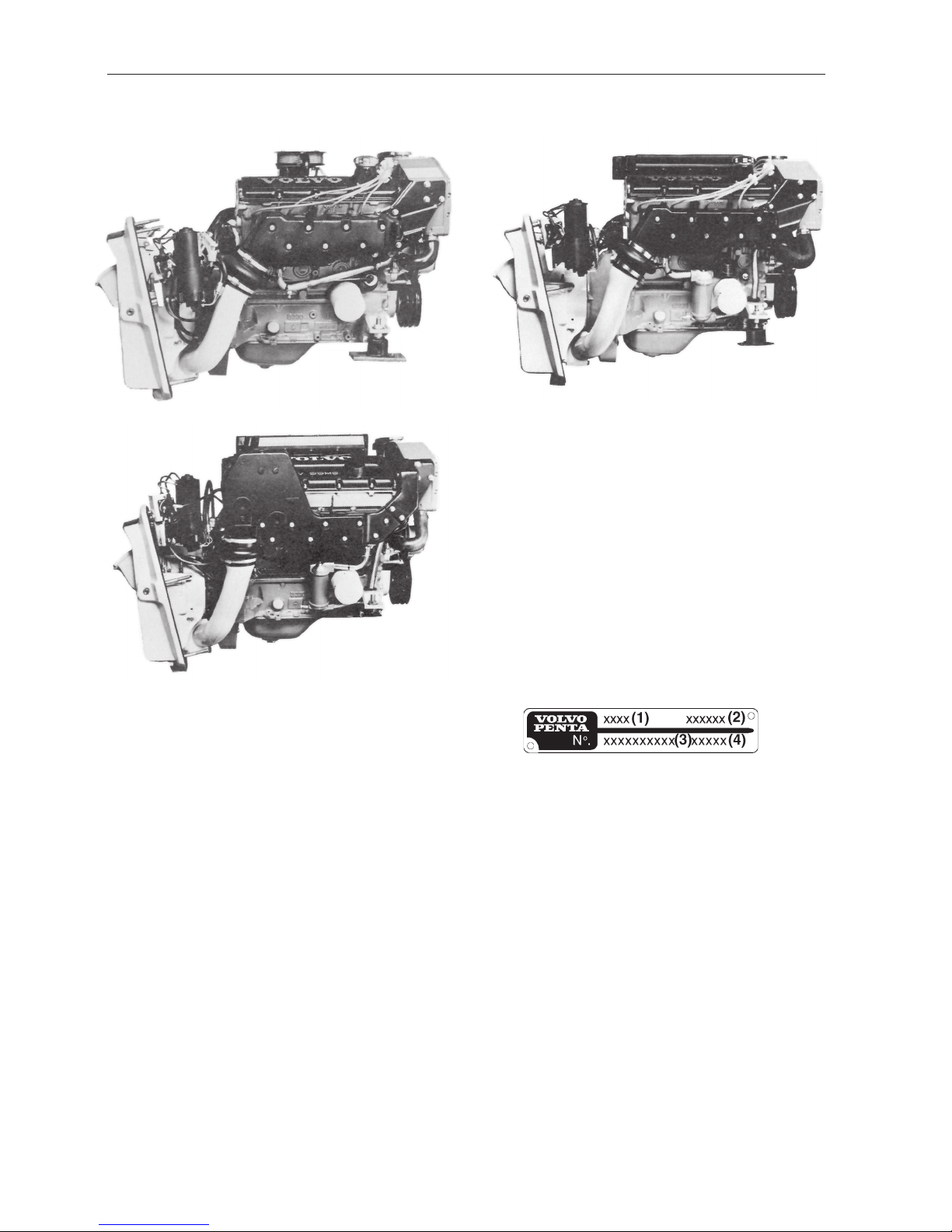
The product plate is located on the cylinder block
beside the starter motor. The product plate provides
the following information;
(1) Product designation, i.e. AQ131D
(2) Product number, i.e 867902
(3) Serial number (10 digit)
(4) Basic engine, serial number
Product plate
230, AQ131
250, AQ151
251DOHC, AQ171
9
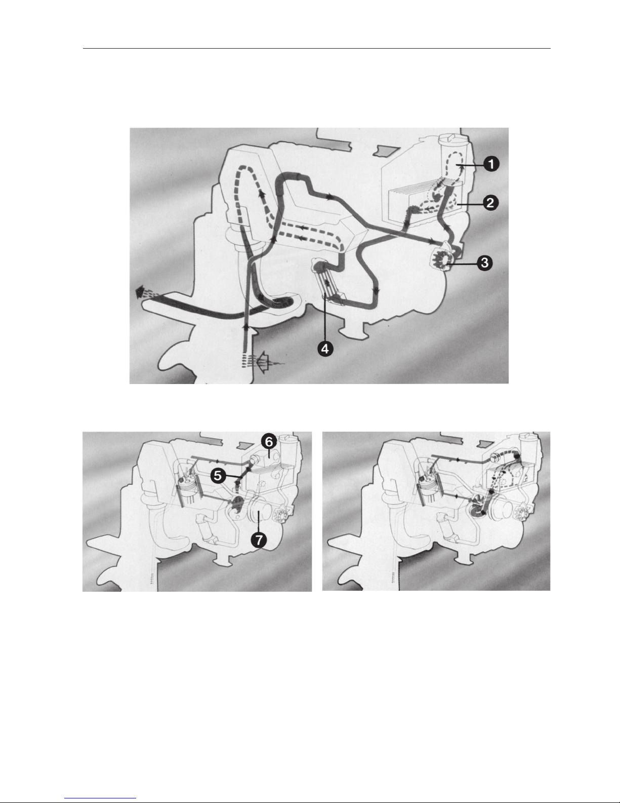
The sea water cooling system
The fresh water cooling system,
thermostat closed
The fresh water cooling system,
thermostat open
1 = Sea-water filter
2 = Heat exchanger
3 = Sea-water pump
4 = Oil cooler
5 = Bypass
6 = Thermostat house
7 = Circulation pump
The Cooling System
10
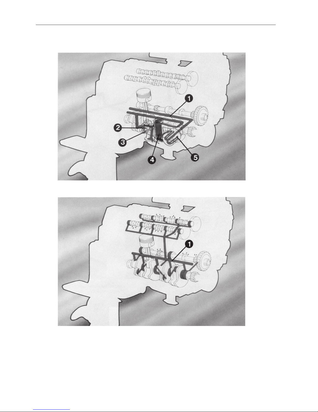
The Lubricating System
The engine lubricating system from strainer to the main gallery
The engine lubricating system from the main gallery to the lubricating points.
1 = Main gallery
2 = Oil pump
3 = Return line
4 = Oil cooler
5 = Oil filter

11
Trouble-shooting Scheme
Main switch open. Battery
discharged. Wires broken or
fuse blown.
Empty fuel tank, closed fuel cock,
clogged fuel filter.
Water or impurities in the fuel.
Faulty spark plugs.
Burned breaker points, moisture
in distributor and ignition leads.
Faulty electronic unit 251DOHC,
AQ171
Idling speed not adjusted properly.
Faulty tachometer.
Boat loaded abnormally.
Growth on boat bottom and
sterndrive.
Damaged propeller.
Clogged cooling water intake, oil
cooler (250, 251DOHC, AQ151,
AQ171) waterjackets. Damaged
impeller or thermostat. Too low
coolant level in expansion tank
Wrong fuel quality in relation to
timing
Toothed belt faulty or not adjusted
properly.
Engine
does not
start
Engine
stops
Engine does
not reach operating speed
at full throttle
Engine runs
rough or vibrates abnormally
Engine becomes abnormally hot
Fault reason
X
X
X
XX
X
X
X
X
X
X
X
X
X
X
X
X
X
X
X
X
X
X

12
1. Overhaul Data
Technical Data
230, 250, 251DOHC
AQ131, AQ151, AQ171
General
Type designation ................................................................................. 230, AQ131
Type of engine ..................................................................................... 4 stroke, overhead cam
Speed range full load ........................................................................... 78.3–83.3 r/s (4700–5000 rpm)
Maximum cruising speed .................................................................... 3.33 r/s (200 rpm) lower than the max speed obtained
Compression ratio ............................................................................... 9.7:1
Compression pressure at starter motor speed
1)
.................................. 10–12 kp/cm2 (142–170 psi)
Number of cylinders ............................................................................ 4 in line
Cylinder bore ....................................................................................... 96 mm (3.7795")
Stroke.................................................................................................. 80 mm (3.1496")
Swept volume (displacement) ............................................................. 2.315 dm3 (141.3 in3)
Weight, excluding water and oil, approx. ............................................. 240 Kilos (529.1 lbs)
Idling speed ......................................................................................... 15 r/s (900 rpm)
General
Type designation ................................................................................. 250, AQ151
Type of engine ..................................................................................... 4 stroke, overhead cam
Speed range full load ........................................................................... 80–91.7 r/s (4800–5500 rpm)
Maximum cruising speed .................................................................... 3.33 r/s (200 rpm) lower than the max speed obtained
Compression ratio ............................................................................... 9.7:1
Compression pressure at starter motor speed1).................................. 10–12 kp/cm2 (142–170 psi)
Number of cylinders ............................................................................ 4 in line
Bore..................................................................................................... 96 mm (3.7795")
Stroke.................................................................................................. 86 mm (3.3858")
Swept volume (displacement) ............................................................. 2.49 dm3 (151.9 in3)
Weight, excluding water and oil, approx. ............................................. 250 Kilos (551.2 lbs)
Idling speed ......................................................................................... 15 r/s (900 rpm)
General
Type designation ................................................................................. 251DOHC, AQ171
Type of engine ..................................................................................... 4 stroke, overhead cams
Speed range full load ........................................................................... 83.3–95 r/s (5000–5700 rpm)
Maximum cruising speed .................................................................... 3.33 r/s (200 rpm) lower than the max speed obtained
Compression ratio ............................................................................... 9.7:1
Compression pressure at starter motor speed1).................................. 10–12 kp/cm2 (142–170 psi)
Number of cylinders ............................................................................ 4 in line
Bore..................................................................................................... 96 mm (3.7795")
Stroke.................................................................................................. 86 mm (3.3858")
Swept volume (displacement) ............................................................. 2.49 dm3 (151.9 in3)
Weight, excluding water and oil, approx. ............................................. 289 Kilos (637.15 lbs)
Idling speed ......................................................................................... 15 r/s (900 rpm)
1)
Applies to hot engine, wide open throttle

13
Cylinder block
Material................................................................................................ Cast iron
Bore, standard..................................................................................... 96.00–96.03 mm (3.7795–3.7807")
Bore, oversize 1 .................................................................................. 96.300 mm (3.79133")
Bore, oversize 2 .................................................................................. 96.600 mm (3.80315")
The cylinder bores should be bored at a wear depth of 0.10 mm
(0.004 in) (in case the engine has an abnormal oil consumption).
Pistons
Material................................................................................................ Light alloy
3)
Overall height 230, AQ131 .................................................................. 64.7 mm (2.54724")
Overall height 250, 251DOHC, AQ151, AQ171 .................................. 61.7 mm (2.42913")
Height from gudgeon pin center to top of piston
230, AQ131 ......................................................................................... 39.7 mm (1.56299")
Height from gudgeon pin center to top of piston
250, 251 DOHC, AQ151, AQ171 ........................................................ 36.7 mm (1.44488")
Piston clearance, production ............................................................... 0.010–0.030 mm (0.0004–0.0012")
Piston clearance, service.................................................................... max 0.080 mm (0.0031")
Piston, standard dimension ................................................................. 95.980–96.010 mm4) (3.779–3.780")
Piston, oversize 1................................................................................ 96.280–96.290 mm (3.791–3.7909")
Piston, oversize 2................................................................................ 96.580–96.590 mm (3.802–3.803")
3)
Maximum weight difference between pistons in the same engine is 16 grams (0.56 oz).
4)
See the spare parts catalog for all the products.
Piston rings
Piston ring end gap (oil scraper ring)................................................... 0.30–0.60 mm (0.0118–0.0236")
Piston ring end gap (compression ring) ............................................... 0.30–0.55 mm (0.0118–0.0217")
Oversize piston rings 1 ....................................................................... 0.3 mm (0.0118")
Oversize piston rings 2 ....................................................................... 0.6 mm (0.0236")
Compression rings
The upper ring is chromium plated. The low er ring is marked “T OP”.
Number of rings on each piston........................................................... 2
Height, upper ....................................................................................... 1.728–1.740 mm (0.068–0.069")
Height, lower ....................................................................................... 1.728–1.740 mm (0.068–0.069")
Piston ring clearance in groove, upper ................................................ 0.040–0.072 mm (0.0016–0.0028")
Piston ring clearance in groove, lower................................................. 0.040–0.072 mm (0.0016–0.0028")
Oil scraper rings
Number on each piston ....................................................................... 1
Height.................................................................................................. 3.475–3.490 mm (0.1368–0.374")
Gudgeon pins
Full floating pin. Locked at both ends with circlips.
Fit in connecting rod ............................................................................ Light thumb pressure (push fit)
Fit in piston .......................................................................................... Thumb pressure (slide fit)
Standard diameter ............................................................................... 23.0 mm (0.906")
Oversize diameter ............................................................................... 23.05 mm (0.907")
Length ................................................................................................. 65 mm (2.559")
14
AQ131A, 131B, AQ131C, 131D,
151A, 151B, 151C, 151D, 171C, 171D,
171A, 171B 230, 250, 251DOHC
Crankshaft
Crankshaft, axial clearance................................................................. 0.080–0.270 mm 0.080–0.270 mm
(0.0031–0.0106") (0.0031–0.0106")
Main bearing, radial clearance............................................................. 0.024–0.072 mm 0.024–0.064 mm
(0.00094–0.00283") (0.0009–0.0025")
Crank bearing, radial clearance .......................................................... 0.023–0.067 mm 0.023–0.067 mm
(0.00091–0.00264") (0.00091–0.00264")
Straightness, maximum deviation........................................................ 0.025 mm 0.025 mm
(0.00098") (0.00098")
Taper Out-of-roundness
Main bearings
Main bearing journals
Out of roundness, max........................................................................ 0.004 mm 0.004 mm
(0.00016") (0.00016")
Taper, max. .......................................................................................... 0.004 mm 0.004 mm
(0.00016") (0.00016")
Standard diameter ............................................................................... 54.987–55.000 mm 62.987–63.000 mm
(2.1648–2.1654") (2.4798–2.4803")
0.25 mm undersize (0,0098") .............................................................. 54.737–54.750 mm 62.737–62.750 mm
(2.1550–2.1555") (2.4700–2.4705")
0.50 mm undersize (0,0197") .............................................................. 54.487–54.500 mm 62.487–62.500 mm
(2.1452–2.1457") (2.4601–2.4606")
Seat width on crankshaft for thrust bearings
Standard.............................................................................................. 31.96–32.00 mm 35.46–35.50 mm
(1.2583–1.2598") (1.3961–1.3976")
Oversize 1........................................................................................... 32.21–32.25 mm –
(1.2681–1.2697")
Oversize 2........................................................................................... 32.46–32.50 mm –
(1.2780–1.2795")
The main bearings are available in two mak es. The upper and lower
main bearing shell on the same pivot must be of the same make.
In production matched crankshaft bearing shells are used. The
bearing shells are color coded, red, yellow and blue. They are matched
in accordance with one of the following alternatives:
Alternative 1: Two yellow-marked bearing shells.
Alternative 2: One blue-marked and one red-marked bearing shell. The
blue-marked shell to be located on the crankshaft and the red-marked
shell in the bearing cap.
NOTE! Only yellow-mark ed bearing shells are av ailable f or spare parts
purposes.
Connecting rods
Connecting Rod Bearings
Bearing journals
Out of roundness, max........................................................................ 0.004 mm (0.00016")
T aper, max. .......................................................................................... 0.004 mm (0.00016")
Bearing seat width............................................................................... 23.9–26.1 mm (0.9409–1.0276")
Standard diameter ............................................................................... 48.984–49.005 mm (1.9285–1.9293")
0.25 mm undersize (0.0098") .............................................................. 48.734–48.755 mm (1.9187–1.9195")
0.50 mm undersize (0.0197") .............................................................. 48.484–48.505 mm (1.9088–1.9096")
Axial clearance at the piston ............................................................... 0.25–0.45 mm (0.0098–0.0177")
Length, center to center ...................................................................... 152 mm (5.9843")
Max. weight difference between connecting rods in the same engine . 20 grams (0.7055 oz.)
Color code

15
Camshaft
Number of bearings ............................................................................. 5
Bearing, diameter ................................................................................ 29.95–29.97 mm (1.179–1.180")
Radial clearance ................................................................................. 0.030–0.071 mm (0.0012–0.0028")
Maximum............................................................................................. 0.15 mm (0.0059")
Axial clearance (end play)................................................................... 0.1–0.4 mm (0.0039–0.0157")
Camshaft bearings
Camshaft bearing diameter ................................................................. 30.000–30.021 mm (1.1811–1.1819")
Timing gears, Models 230, 250, AQ131, A Q151
Number of teeth, crankshaft gear........................................................ 19
Number of teeth, intermediate shaft gear ............................................ 38
Number of teeth, camshaft gear .......................................................... 38
Number of teeth, toothed belt .............................................................. 123
Timing gears, Models 251DOHC, A Q171
Number of teeth, crankshaft gear........................................................ 19
Number of teeth, intermediate shaft gear ............................................ 38
Number of teeth, camshaft gear .......................................................... 38
Number of teeth, toothed belt .............................................................. 146
Intermediate shaft
Number of bearings ............................................................................. 3
Front bearing diameter......................................................................... 46.975–47.000 mm (1.849–1.850")
Middle bearing diameter ...................................................................... 43.025–43.050 mm (1.694–1.695")
Rear bearing diameter ......................................................................... 42.925–42.950 mm (1.690–1.691")
Radial clearance ................................................................................. 0.020–0.075 mm (0.0008–0.0030")
Axial clearance (end play)................................................................... 0.20–0.46 mm (0.0079–0.0181")
Intermediate shaft bearing diameter in block:
Front................................................................................................. 47.020–47.050 mm (1.851–1.852")
Middle .............................................................................................. 43.070–43.100 mm (1.696–1.697")
Rear ................................................................................................. 42.970–43.000 mm (1.692–1.693")
Changing the bearings
NOTE! New bearings must be line bored!
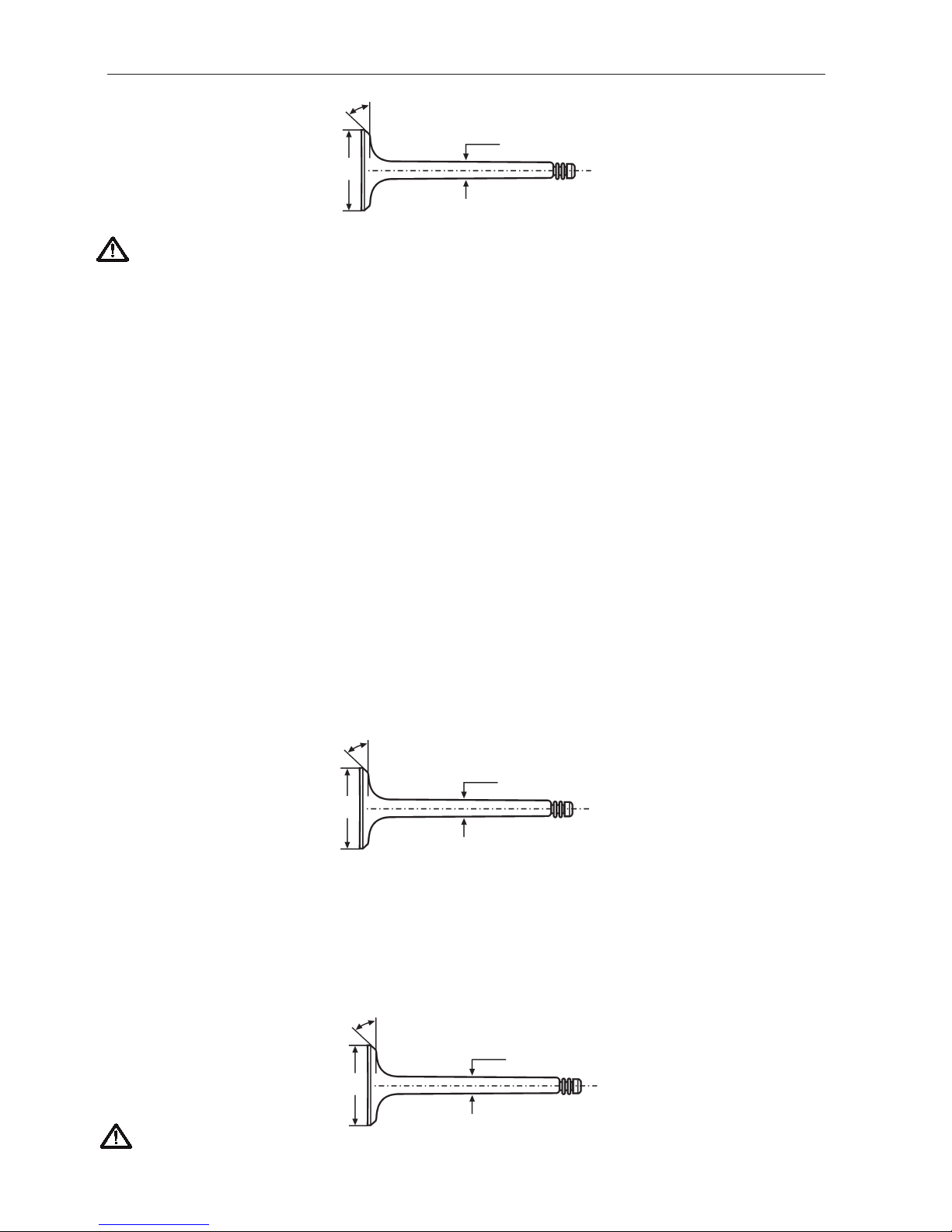
Valves 230, 250, A Q131, A Q151
Inlet
Disc diameter ...................................................................................... 44.0 mm (1.7323")
Stem diameter ..................................................................................... 7.955–7.970 mm (0.3132–0.3138")
Valv e seat angle.................................................................................. 44.5°
Cylinder block seat angle .................................................................... 45°
Seat width in cylinder head.................................................................. 1.3–1.9 mm (0.0512–0.0748")
Exhaust
Disc diameter ...................................................................................... 35.0 mm (1.37795")
Stem diameter ..................................................................................... 7.945–7.960 mm (0.3128–0.3134")
Valv e seat angle.................................................................................. 44.5°
Cylinder block seat angle .................................................................... 45°
Seat width in cylinder head.................................................................. 17–2.3 mm (0.0669–0.0906")
44.5°
44.0
New: 7.955–7.970 (0.3132–0.3138")
Min: 7.935 (0.3124")
Inlet valve
16
IMPORTANT! The valves are stellite coated. Therefore they must not be machined, only lapped against the seat!
Clearance when checking:
Cold engine ......................................................................................... 0.30–0.40 mm (0.0118–0.0157")
Hot engine ........................................................................................... 0.35–0.45 mm (0.0138–0.0177")
Clearance when adjusting:
Cold engine ......................................................................................... 0.35–0.40 mm (0.0138–0.0157")
Hot engine ........................................................................................... 0.40–0.45 mm (0.0157–0.0177")
The same clearance for inlet and exhaust valves.
Valve guides (inlet & exhaust) 230, 250, A Q131, A Q151
Length ................................................................................................. 52 mm (2.165")
Inner diameter ..................................................................................... 8.00–8.02 mm (0.275–0.276")
Clearance, valve stem–valve guide, inlet valve................................... 0.03–0.06 mm (0.0012–0.00245")
Clearance, valve stem–valve guide, exhaust valve ............................ 0.04–0.07 mm (0.0016–0.0028")
Clearance, maximum wear.................................................................. 0.15 mm (0.0059")
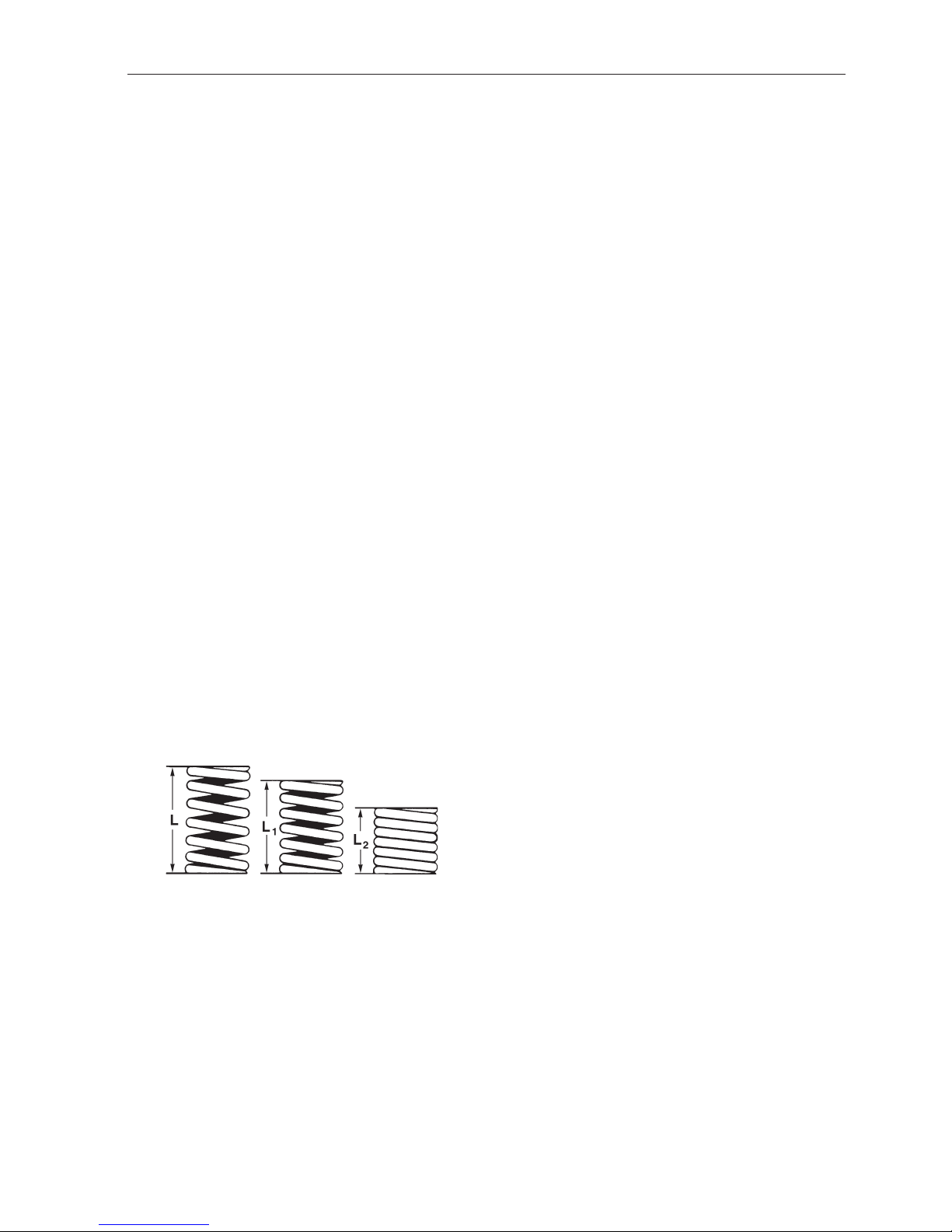
Valve springs, 230, 250, A Q131, AQ151
Length, unloaded ................................................................................. 45.0 mm (1.772")
Length, loaded 285–325 N (28.5–32.5 kp)........................................... 38.0 mm (1.496")
Length, loaded 725–805 N (72.5–80.5 kp)........................................... 27.0 mm (1.063")
Valves 251DOHC, A Q171
Inlet
Disc diameter ...................................................................................... 34.5 mm (1.358")
Stem diameter ..................................................................................... 6.955–6.970 mm (0.2738–0.2744")
Valv e seat angle.................................................................................. 44.5°
Cylinder block seat angle .................................................................... 45°
Seat width in cylinder head.................................................................. 1.3–1.9 mm (0.0512–0.0748")
Exhaust
Disc diameter ...................................................................................... 31.5 mm (1.240")
Stem diameter ..................................................................................... 6.945–6.960 mm (0. 2734–0.2740")
Valv e seat angle.................................................................................. 44.5°
Cylinder block seat angle .................................................................... 45°
Seat width in cylinder head.................................................................. 1.7–2.3 mm (0.0669–0.0906")
IMPORT ANT! The valves are stellite coated. Theref ore they m ust not be machined, only lapped against the seat.
New: 7.945–7.960 (0.3128–0.3134)
Min: 7.925 (0.3120")
35.0
44.5°
New: 6.955–6.970 (0.2738–0.2744")
Min: 6.935 (0.2730")
34.5
44.5°
New: 6.945–6.960 (0.2734–0.2740")
Min: 6.925 (0.2726")
31.5
44.5°
Inlet valve
Exhaust valve
Exhaust valve
17
Valve clearance, 251DOHC, AQ171................................................... Hydraulic valve tappets, no setting is required
Valve guides (inlet & exhaust) 251DOHC, A Q171
Length ................................................................................................. 55 mm (2.165")
Inner diameter ..................................................................................... 7.00–7.02 mm (0.275–0.276")
Clearance, valve stem–valve guide, inlet valve................................... 0.03–0.06 mm (0.0012–0.0024")
Clearance, valve stem–valve guide, exhaust valve ............................ 0.04–0.07 mm (0.0016–0.0028")
Clearance, maximum wear.................................................................. 0.15 mm (0.0059")
Valve springs 251DOHC, A Q171
Length, unloaded ................................................................................. 43.0 mm (1.6929")
Length, loaded 212–252 N (21.2–25.2 kp)........................................... 37.0 mm (1.45669")
Length, loaded 600–680 N (60–68 kp)................................................. 26.5 mm (1.0433")
Lubricating system
Changing oil, oil capacity , e xcluding filter ............................................ 3.5 dm3 (0.88 Imp gall./1.06 US gall.)
Changing oil, oil capacity , including filter ............................................. 4.0 dm3 (0.99 Imp gall./1.19 US gall.)
Oil pressure at 33.33 r/s (2000 rpm), hot engine ................................. 2.5–6.0 kp/cm2 (35–85 psi)
Lubricating oil, alternative 1 ................................................................. Volvo P enta lubricating oil for gasoline engines
Lubricating oil, alternative 2 ................................................................. Lubricating oil SG
Viscosity ............................................................................................. SAE 20 W/50
Oil filter
Type..................................................................................................... Full flow filter
Lubricating oil pump
Axial clearance.................................................................................... 0.02–0.12 mm (0.0008–0.0047")
Radial clearance (excluding bearing clearance).................................. 0.02–0.09 mm (0.0008–0.0035")
Gear backlash (excluding bearing clearance)..................................... 0.15–0.35 mm (0.0059–0.0138")
Bearing clearance, drive shaft............................................................. 0.032–0.070 mm (0.0013–0.0028")
Bearing clearance, idler shaft .............................................................. 0.014–0.043 mm (0.0006–0.0017")
Length of the relief valve spring at different loads:
Length: Load:
47.6 mm (1.874") No load
32.0 mm (1.26") 40–48 N (4.0–4.8 kp)
(29.4–35.2 ft.lbs)
26.0 mm (1.024") 55–67 N (5.5–6.7 kp)
(40.3–49.1 ft.lbs)
Fuel system
Fuel pump
Type..................................................................................................... Diaphragm
Feed pressure ..................................................................................... 0.15–0.28 kp/cm2 (2–4 psi)
Fuel flow .............................................................................................. 1.6–2.0 liter/minute
(0.35–0.44 Imp.gal/min/0.375–0.475 US gal/min)

18
Carburetor 230, A Q131 AQ131A, 131B AQ131C,131D, 230
Type..................................................................................................... Down draught Down draught
Designation ......................................................................................... Model 44 P AI-5 Model 44 PAI-7
Venturi ................................................................................................. 34 34
Main jet................................................................................................ 165 165
Idling jet ............................................................................................... 65 65
Air jet ................................................................................................... 185 1 8 5
Needle valve ....................................................................................... 1.7 2.0
Float, weight in grams (oz’s)................................................................ 7.3 (0.26) 7.3 (0.26)
Acceleration jet.................................................................................... 70 70
Econostat jet ....................................................................................... 110 11 0
Carburetor 250, A Q151 AQ151A, AQ151B AQ151C, AQ151D , 250
Type..................................................................................................... Down draught Down draught
Designation ......................................................................................... Model 44 P AI-4 Model 44 PAI-7
Venturi ................................................................................................. 31 31
Main jet................................................................................................ 145 145
Idling jet ............................................................................................... 62 62
Air jet ................................................................................................... 185 1 8 0
Needle valve ....................................................................................... 1.5 1.7
Float, weight in grams (oz’s)................................................................ 7.3 (0.26) 7.3 (0.26)
Acceleration jet.................................................................................... 60 60
Econostat jet ....................................................................................... – –
AQ171C, A Q171D ,
Carburetor 251DOHC, A Q171 AQ171A, A Q171B 251DOHC
Type..................................................................................................... Down draught Down draught
Designation ......................................................................................... Model 44 P AI-5-6 Model 44 P AI-7
V enturi ................................................................................................. 32 32
Main jet................................................................................................ 147 147
Idling jet ............................................................................................... 65 60
Air jet ................................................................................................... 190 2 0 0
Needle valve ....................................................................................... 1.7 1.7
Float, weight in grams (oz’s)................................................................ 7.3 (0.26) 7.3 (0.26)
Acceleration jet.................................................................................... 70 70
Econostat jet ....................................................................................... – –
Electrical system
Battery
Grounding............................................................................................ Negative
V oltage ................................................................................................ 12 Volts
Capacity .............................................................................................. 60 Ah
Specific weight of the electrolyte
Fully charged battery........................................................................... 1.275–1.285 grams/cm3 (0.0460–0.0464 lb/cu.in.)
Discharged battery.............................................................................. 1.230 grams/cm3(0.0444 lb/cu.in.)
Starter motor
Output ................................................................................................. 0.8 kW (1.1 hk)
Alternator
Output, maximum Amp (W) ................................................................. 50 (14x50)
Ignition system
Cylinder marking ................................................................................. No 4 closest to the flywheel
Spark plugs 230, 250, AQ131, AQ151 ................................................ Part no 875820-3, Bosch W6DC or its equivalent
Spark plugs, 251DOHC, AQ171 ......................................................... Part no 876077-9, Bosch WR6DC or its equivalent
Spark plug gap .................................................................................... 0.7 mm (0.0276")
19
Distributor 230, 250, A Q131, A Q151
Type..................................................................................................... Breaker point system
Type Bosch JF4 .................................................................................. 0231 178 019
Setting for regular gasoline, min 91 octane RO T :
USA: Ignition setting for regular petrol (RON+MON)/2 = min 87 octane
Basic setting........................................................................................ 6° BTDC (0–14.17 r/s = 0–850 rpm)
Stroboscope setting ............................................................................ 32–36° BTDC (70 r/s = 4200 rpm)
Contact gap ......................................................................................... 0.40 mm (0.01575")
Dwell angle.......................................................................................... 62±3°
Distributor , 251DOHC, A Q171
Type Bosch TVX4, Breakerless system.............................................. A 237 540 079
Setting for regular gasoline, min 91 octane RO T :
USA: Ignition setting for regular petrol (RON+MON)/2 = min 87 octane
Basic setting........................................................................................ 10° BTDC (0–15 r/s = 0–900 rpm)
Stroboscope setting (not adjustable) ................................................... 23–25° BTDC (73.33 r/s=4400 rpm)
Cooling system
Thermostat
Type..................................................................................................... Wax thermostat
Starts opening at ................................................................................. 82°C (179.6°F)
Fully open at ........................................................................................ 92°C (197.6°F)
Tightening torques
NOTE! Alwa ys tighten the cylinder head bolts when the
engine is cold. The torque v alues are valid f or bolts and
nuts being well oiled prior to installation.
Parts having been washed should be oiled prior to
the assembly.
Tightening torque for cylinder head bolts:
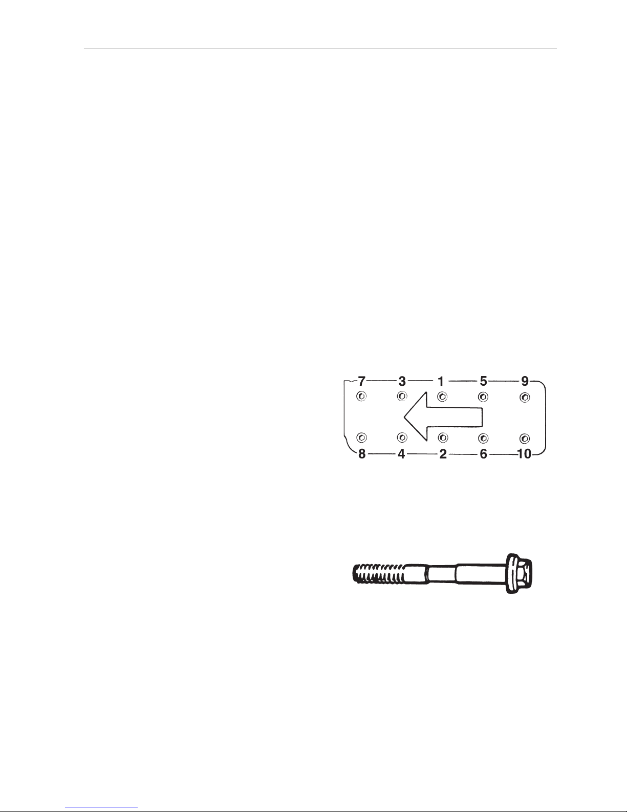
The cylinder head: To be tightened in stages....................................... 1 = 20 Nm (2.0 kpm) (15 ft.lbs.)
2 = 40 Nm (4.0 kpm) (29 ft.lbs.)
3 = Angle tighten through 120° in one operation!
– Replace the cylinder head bolts if they show signs of being
stretched. If a bolt is “stretched” can clearly be seen on the
“waist” of the bolt, which is then elongated.
– The cylinder head bolts can be “re-used” max 5 times.
Replace the bolts if you feel uncertain on any of these points.
Nm Kpm Ft.lbs.
Main bearings ...................................................................................... 110 11.0 79.5
Crank bearings, 1st stage1)................................................................ 20 2.0 15
2nd stage1)............................................................... through 90°
Flywheel (use new bolts) .................................................................... 70 7.0 51
Spark plugs (do not oil them!).............................................................. 25±5 2.5±0.5 18
Camshaft gear..................................................................................... 50 5.0 36
Intermediate gear ................................................................................ 50 5.0 36
Camshaft bearing cap ......................................................................... 20 2.0 15
Crankshaft, center bolt pulley, stage 1................................................ 60 6.0 43
stage 2................................................ Angle tighten through 60°
1)
Old bolts can be used provided the length does not exceed 55.5 mm (2.185").
20
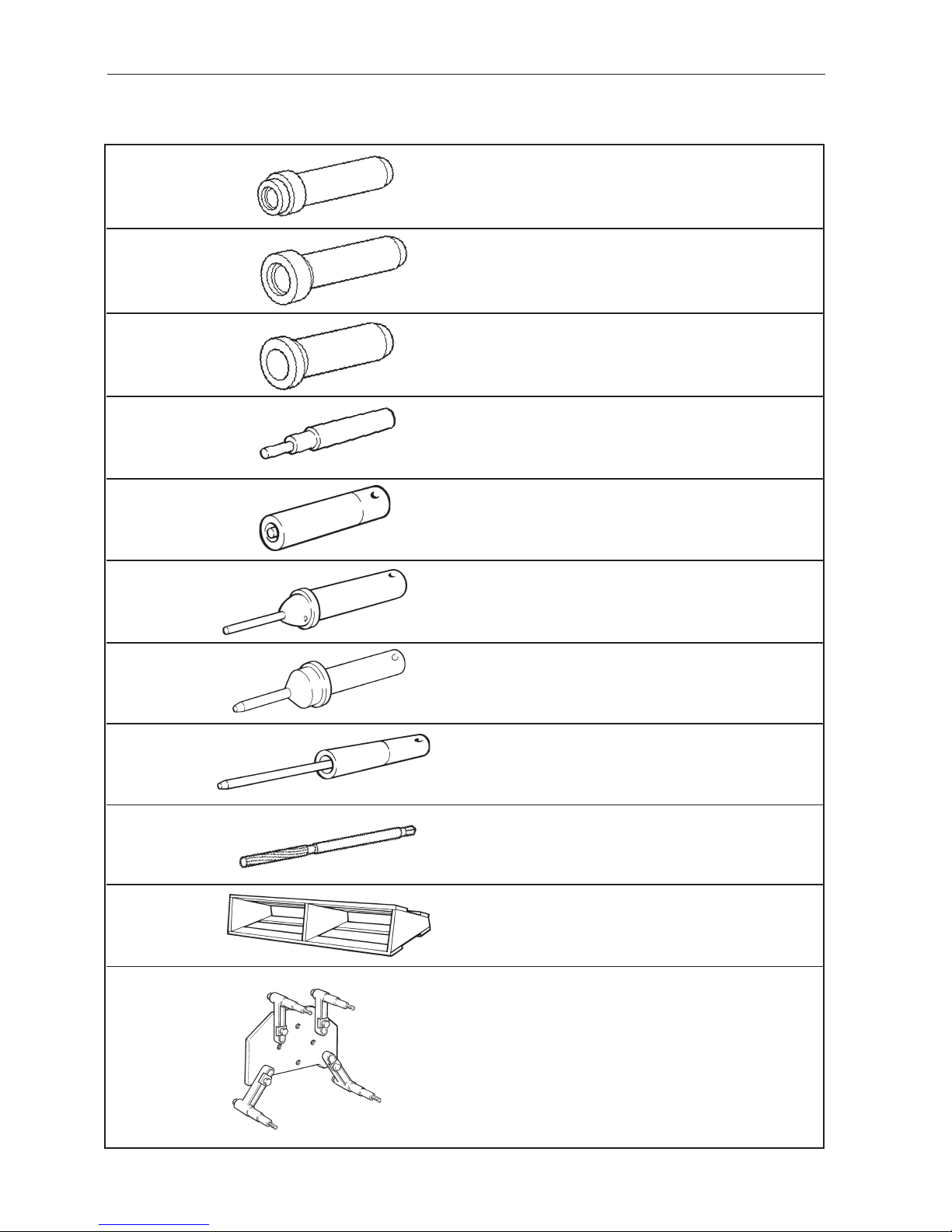
2. Special T ools
884359-1 Drift for the installation of the seal in the flywheel
housing
885050-5
884596-8
884599-2
884958-0
884959-0
884960-6
884961-4
884967-1
884966-3
884979-6
Drift for the installation of the primary shaft in the
flywheel housing
Drift for the installation of the seal in the flywheel
housing
Drift for the changing of valve guides 251DOHC ,
AQ171
Drift for the changing of valve guides 251DOHC,
AQ171
Drift for the changing of valve guides 251DOHC,
AQ171
Reamer valve guides 251DOHC, AQ171
Cylinder head fixture 251DOHC, AQ171
Stand fixture
Installation tool inlet valve seat 251DOHC, AQ171
Installation tool exhaust valve seat 251DOHC,
AQ171
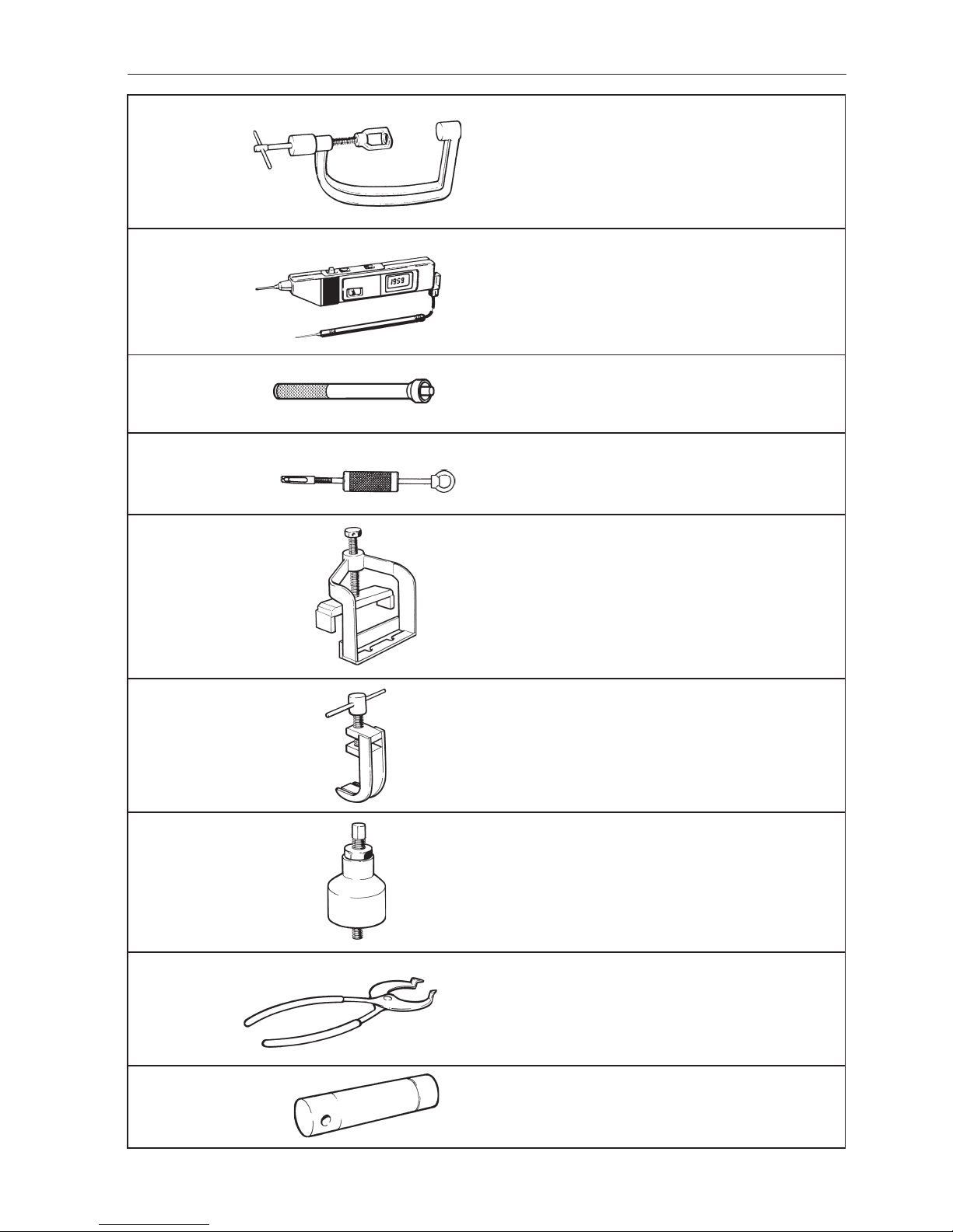
21
9986052-0 Valve com-
pressor
9991426-9
Drift for the installation of support bearing in the flywheel
9994090-0
Puller for support bearing in the flywheel
9995021-4 Press tool for the removal and assembly of the
camshaft, AQ131, AQ151, 230, 250
9995022-2
Tool for depressing valve depressors, AQ131,
AQ151, 230, 250
9995025-5
Installation tool for the intermediate shaft seal
9995026-3
9995027-1
Pair of pliers for adjustment shims AQ131, AQ151,
230, 250
Drift for the installation of valve guides (inlet),
AQ131, AQ151, 230, 250
9988452-0
Digital probe tester
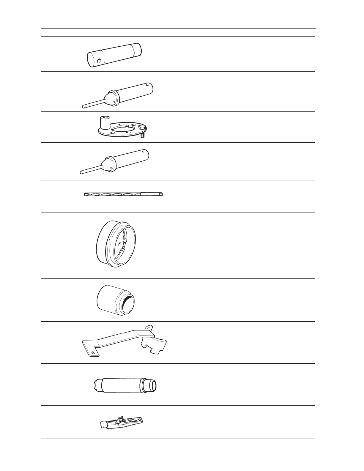
22
9995029-7
9995034-7
9995224-4
9995276-4
9995283-0
9995220-2
9995284-8
9995309-3
1159660-8
Installation tool for valve seats (inlet), AQ131,
AQ151, 230, 250
Counterhold for the camshaft gear and intermediate
gear
Installation tool for valve seats (exhaust), AQ131,
AQ151, 230, 250
Reamer, valve guides AQ131, AQ151, 230, 250
Drift for the installation of sealing in the crankshaft
rear end
Removal tool for the crankshaft front seal
Counterhold for crankshaft pulley
Drift for the removal and installation of bushing in
the connecting rod
Tensioning tool for the toothed belt AQ171,
251DOHC
9995028-9
Drift for the installation of valve guides (exhaust),
AQ131, AQ151, 230, 250

23
3. Electrical System
General
All engines have a single pole electrical system with
an AC generator. The engine main wiring is fused
with a thermic 40 A automatic fuse.
Ignition system
AQ131, AQ151, 230 and 250 have conventional
breaker point ignition systems. See the “Technical
Data” for the setting values. AQ171 and 251DOHC
are equipped with breakerless electronic ignition
systems. The ignition system memory unit has 63
optimal engine speed / ignition values programmed.
The ignition points for other engine speeds is
calculated based on these locked values.
Note! No ignition setting can be carried out on the
distributor. The ignition system has the correct setting when all components are correctly installed. In
order to obtain exact installation there is a certain
amount of adjustment possible in the ignition setting
sender. All operation based adjustment is stopped.
All settings are permanently stored in the control
module and are stable because of the absence of
mechanicals (breaker points, mechanical ignition
setting). The only task of the distr ibutor has is to
distribute the current to the spark plugs via the rotor.
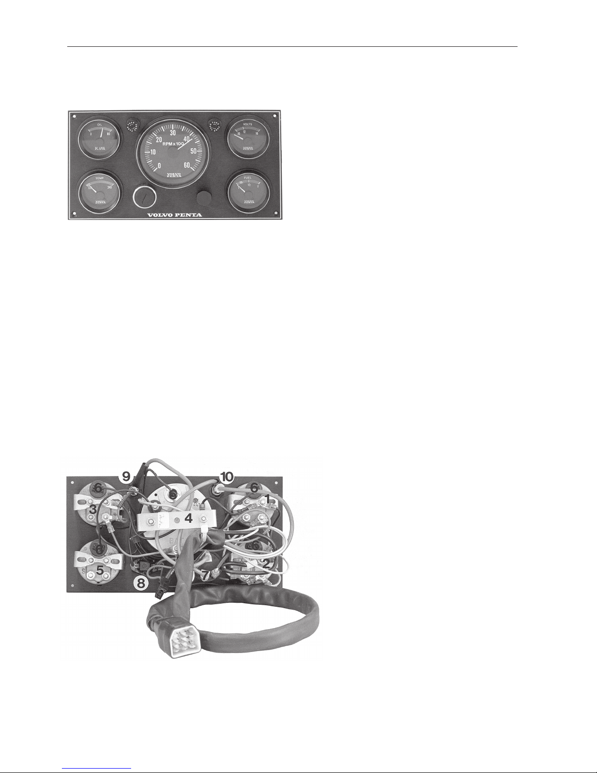
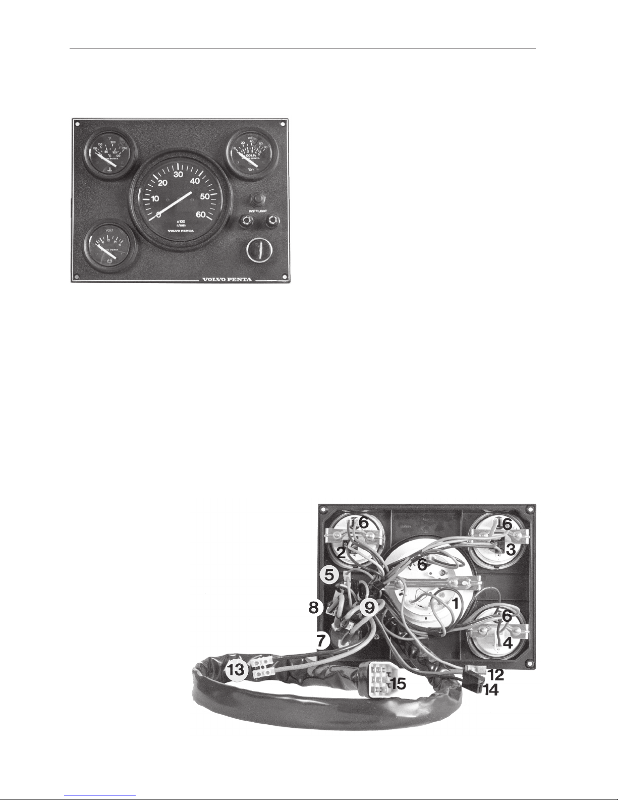
Instrumentation
The engines were manufactured with two types of instrumentation. One earlier type 1 and the later type 2
(for version refer to wiring diagrams). Both the instrumentation types are equipped with two 8 A fuses
for the system voltage (key switch in ignition position) and start voltage (key switch in start position).
Instrumentation type 2 is equipped with 2 connectors
for extra power outputs for accessories. One is
fused via the 8 A fuse for system voltage and has a
maximum permissible voltage output of 5 A (main
panel + any flying bridge panel). The other connector
has a maximum permissible voltage output of 20 A
and is not separately fused (power supply is via the
40 A automatic fuse for the main wiring). There is
also a connector for connecting instrument lighting
for extra instruments (a fuel gauge for example)
fused via the 8 A fuse for system voltage.
Starter motor
There are two versions. VALEO D6RA11 and
Hitachi S114-237.
Minimum length of the brushes:
VALEO = 14 mm
Hitachi = 12 mm.
Generator
The alternating current generator is a 14 V 50 A
VALEO. It is equipped with a charge sensor cable
(yellow) which is connected to the generator
(GEN) B+.
In those cases where the generator is required to
charge several batteries (starter and operational batteries) the charge sensor cable should be disconnected from B+ and connected, using a 1.5 mm
2
extension, to the accessory battery + ter minal using a
double diode.
Minimum length of the brushes: 8 mm
Resistance rotor winding 4,0–6,0 Ω
Resistance stator winding 0,11–0,15 Ω
24
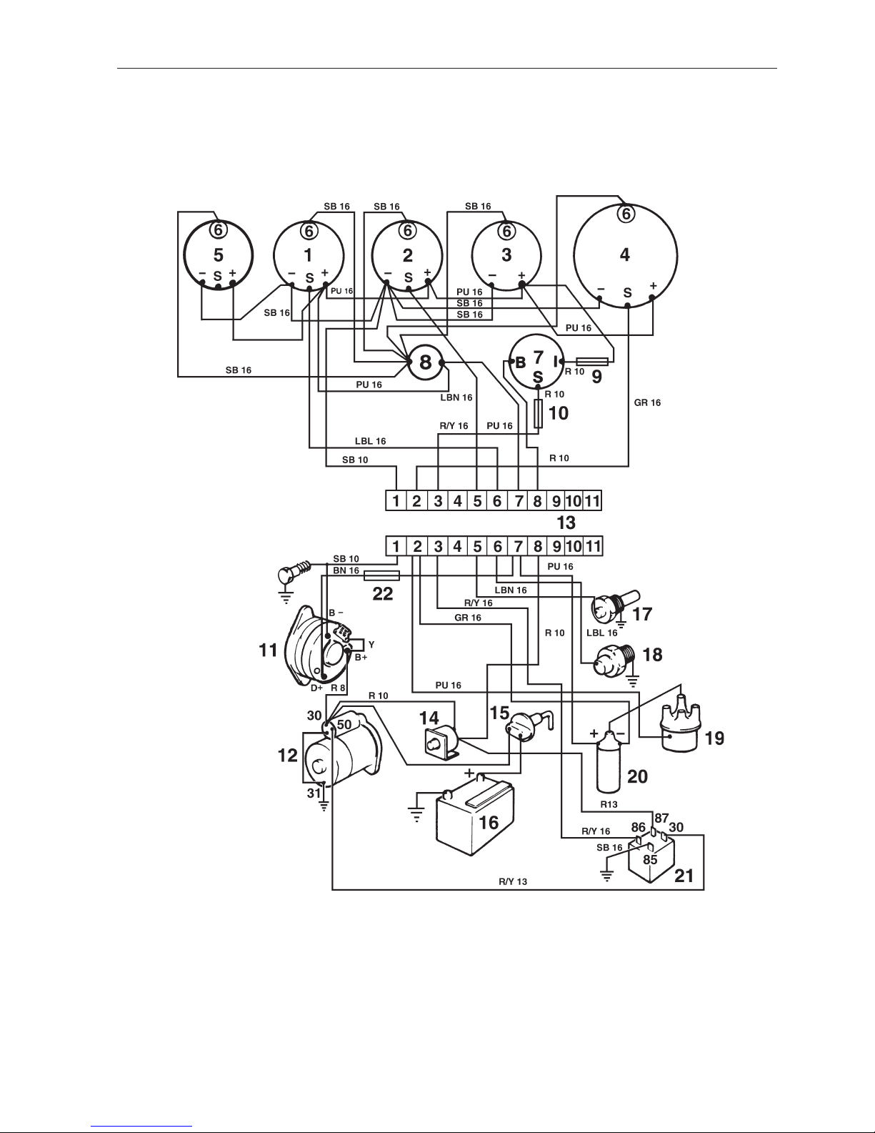
Wiring Diagram AQ131, AQ151, 230, 250
With Instrument panel alternative 1
1. Oil pressure gauge
2. Temperature gauge, coolant
3. Voltmeter
4. Tachometer
5. Fuel gauge (alternative)
6. Instrument lighting
7. Key switch (B=30, S=50, I=15)
8. Switch, instrument lighting
9. Fuse 8 A
10. Fuse 8 A
11. Generator
12. Starter motor
13. Connector engine–instrumentation
14. Automatic fuse 40A
15. Main switch (option)
16. Batte r y
17. Temperature sensor
18. Oil pressure sensor
19. Distributor
20. Ignition coil
21. Relay
22. Resistor
Cable cross sections
AWG mm
2
16 1.5
13 2.5
10 6.0
8 10.0
Cable colour code
SB = Black
PU = Purple
LBN = Light brown
R = Red
GR = Grey
LBL = Light blue
R/Y = Red/Yellow
BN = Brown
W = White
Y = Yellow
13
25
AQ131, AQ151, 230, 250 ALT. 1
26
Wiring Diagram 230, 250
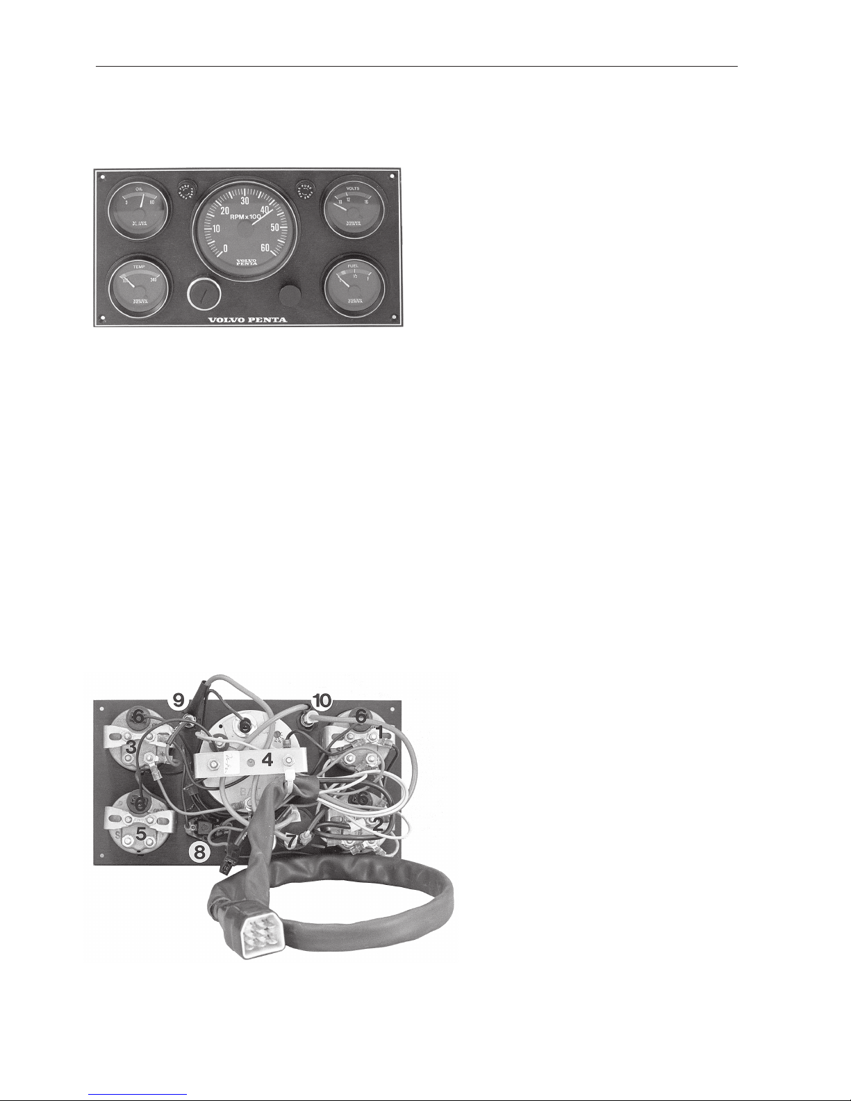
With Instrument panel alternative 2
1. Tachometer
2. Oil pressure gauge
3. Temperature gauge, coolant
4. Voltmeter
5. Switch, instrument lighting
6. Instrument lighting
7. Key switch (B=30, S=50, I=15)
8. Fuse 8 A
9. Fuse 8 A
10. Contact terminal neutral position switch
(option/accessory)
11. Contact terminal safety switch (accessory)
12. Connector instrument lighting accessory
13. Connector power output, maximum 20 A
14. Connector power output, maximum 5 A
(main panel + flying bridge panel)
15. Connector, engine–instrumentation
16. Automatic fuse 40A
17. Main switch (option)
18. Batte r y
19. Temperature sensor
20. Oil pressure sensor
21. Distributor
22. Ignition coil
23. Starter motor
24. Relay
25. Generator
26. Resistor
Cable cross sections
AWG mm
2
16 1.5
13 2.5
10 6.0
8 10.0
Cable colour code
SB = Black
PU = Purple
LBN = Light brown
R = Red
GR = Grey
LBL = Light blue
R/Y = Red/Yellow
BN = Brown
W = White
Y = Yellow
27
230, 250 ALT. 2
28
Wiring Diagram AQ171, 251DOHC
With Instrument panel alternative 1
1 . Oil pressure gauge
2. Temp gauge
3. Voltmeter
4. Tachometer
5. Fuel gauge (alternative)
6. Instrument lights
7. Key switch (B = 30, S = 50, I = 15)
8. Switch, instrument lights
9. Fuse 8 Amp
10. Fuse 8 Amp
11. Alternator
12. Starter motor
13. Terminal block
14. Automatic fuse 40 Amp
15. Main switch (optional)
16. Battery (optional)
17. Temp sender
18. Oil pressure sender
19. Distributor
20. Electronic ignition unit
21. Relay
22. Resistor
23. Impulse sender, ignition unit
24. Ground (screw)
25. Solenoid valve
Cable cross sections
AWG mm
2
16 1.5
13 2.5
10 6.0
8 10.0
Cable colour code
SB = Black
PU = Purple
LBN = Light brown
R = Red
GR = Grey
LBL = Light blue
R/Y = Red/Yellow
BN = Brown
W = White
Y = Yellow
13
 Loading...