

Page 1
VOLVO
OWNERS MANUAL XC90
WEB EDITION
2006
Page 2

Dear Volvo owner
We hope you will enjoy many years of driving pleasure in your Volvo. The car has been designed for the safety and comfort of you and your
passengers. Volvo is one of the safest cars in the world. Your Volvo has also been designed to satisfy all current safety and environmental
requirements.
In order to increase your enjoyment of the car, we recommend that you familiarise yourself with the equipment, instructions and maintenance
information contained in this owner’s manual.
Thank you for choosing Volvo!
1
Page 3
Introduction
WARNING!
IMPORTANT!
Owner’s Manual
A good way of getting to know your new car
is to read the owner’s manual, ideally before
your first journey. This will give you the opportunity to familiarise yourself with new
functions, to see how best to handle the car
in different situations, and to make the best
use of all the car’s features. Please pay
attention to the safety instructions contained
in the manual:
"Warning!" texts indicate where there is a
risk of personal injury in the event of the
instructions not being followed.
"Important!" texts indicate a risk of
damage to the car in the event of the
instructions not being followed.
The equipment described in the owner’s
manual is not present in all models. In
addition to standard equipment, this manual
also describes options (factory fitted
equipment) and certain accessories (extra
equipment).
NOTE! Volvo cars are adapted for the varying
requirements of different markets, as well as
for national or local legal requirements and
regulations.
The specifications, design features and illustrations in this owner’s manual are not
binding. We reserve the right to make modifications without prior notice.
© Volvo Car Corporation
2
Page 4
Volvo Car Corporation and the environment
Volvo Cars’ environmental
philosophy
Environmental care, safety and quality are the
three core values which influence all operations of the Volvo Car Corporation. We also
believe that our customers share our consideration for the environment.
Your Volvo complies with strict international
environmental standards and is also
manufactured in one of the cleanest and most
resource-efficient plants in the world. Volvo
Car Corporation has global certification to
the ISO 14001 environmental standard,
which leads to continuous improvements
within the area of the environment.
EPI (Environmental Product Information)
environmental product decla rations are
supplied for all Volvo models. You can now
compare the environmental impact of
different models and engines.
Read more at www.volvocars.com/EPI.
Fuel consumption
Volvo cars have competitive fuel
consumption in each of their respective
classes. Lower fuel consumption generally
results in lower emission of the greenhouse
gas, carbon dioxide.
It is possible for the driver to influence fuel
consumption, see page 4.
Efficient emission control
Your Volvo is manufactured following the
concept
that encompasses a clean interior
environment as well as highly efficient
emission control. In many cases the exhaust
emissions are well below the applicable
standards.
In addition there is a special radiator coating,
PremAir®1, which can convert hazardous
ground-level ozone into pure oxygen.
Clean inside and out
1. PremAir® is a registered trademark
of Engelhard Corporation.
– a concept
3
Page 5
Volvo Car Corporation and the environment
Clean air in the passenger
compartment
A sophisticated air cleaning system, IAQS
(Interior Air Quality System) ensures that the
air in the passenger compartment is cleaner
than the air outside.
The system consists of an electronic sensor
and a carbon filter. The air intake is closed if
the level of reducing gases and oxidising
gases, e.g. carbon monoxide, becomes too
high, for example in heavy town traffic,
queues and tunnels. The entry of nitrous
oxides, ground-level ozone and hydrocarbons
is prevented by the carbon filter.
1
Textile standard
The interior of a Volvo is designed to be
healthy and safe - even for people with
contact allergies and for asthma sufferers.
Extreme attention has been given to choosing
environmentally-compatible materials. This
means that they also fulfil the requirements of
the Öko-Tex 100 ecological standard - a
major advance towards a healthier cabin
environment.
Öko-Tex certification covers seatbelts,
carpets, thread and fabrics for example. Even
the leather upholstery undergoes chromium-
1. Option.
4
free tanning with natural plant substances
and meets the requirements.
Volvo workshops and the
environment
Regular maintenance carried out by an
authorised Volvo workshop creates the
conditions for long service life and low fuel
consumption, and contributes to a cleaner
environment. When Volvo’s workshops are
entrusted with the repair and maintenance of
the car, it becomes part of our system. We
make clear environmental demands
regarding the way in which workshops are
designed in order to prevent spills and
discharges into the environment, and this
includes the thorough collection and sorting
of the gaseous, liquid and solid waste that
arises in our workshops. Our workshop staff
have the knowledge and the tools required to
guarantee good environmental care.
Reducing environmental impact
You can help reduce environmental impact,
for example, by purchasing eco-labelled car
care products and by servicing and
maintaining the car according to the instructions in the owner’s manual.
The following hints will help you to do your bit
for the environment:
• Ensure that your tyre pressures are
correct. Poorly inflated tyres increase fuel
consumption. If any of the higher tyre
pressures recommended by Volvo are
used then fuel consumption decreases.
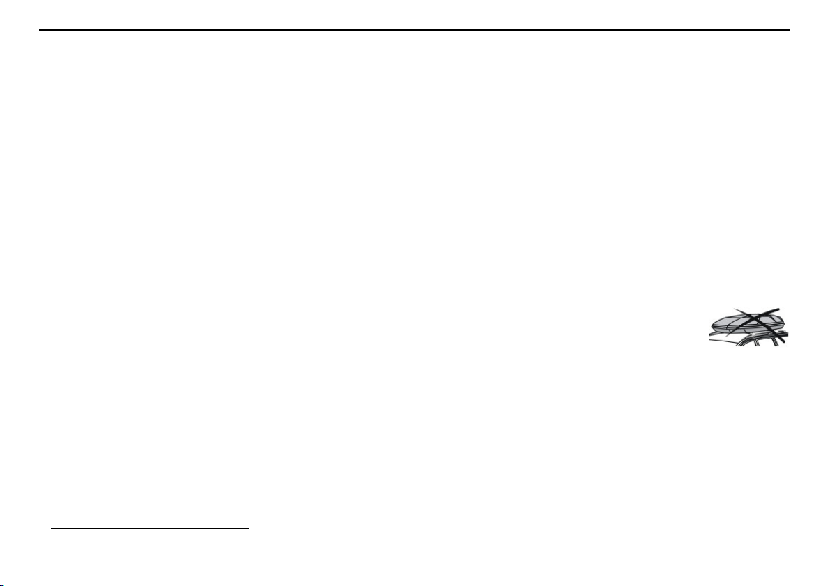
• Since a roof rack and ski
box increase air
resistance, leading to
significantly higher fuel
consumption, they
should be removed
immediately after use.
• Remove unnecessary items from the car the greater the load the higher the fuel
consumption.
• Is your car equipped with an engine block
heater? If so, use it for a few hours before
starting from cold to reduce fuel
consumption and exhaust emissions.
• Drive gently! Avoid accelerating and
braking too hard.
Page 6
Volvo Car Corporation and the environment
• Drive in the highest gear
possible. Low engine
speeds result in lower
fuel consumption.
• Ease back on the accelerator on downhill
gradients.
• Use engine braking. Take your foot off the
accelerator and change down.
• Avoid idling. Switch off the engine in
traffic queues.
• Always dispose of
environmentally
hazardous waste, such
as batteries and oils, in
an environmentally safe
manner. If uncertain,
consult an authorised Volvo workshop for
advice.
• Service your car regularly.
These hints will help you to reduce your fuel
consumption without increasing your travel
time or lessening the enjoyment of driving.
Apart from being kind to your car, you’ll be
saving money - and the Earth’s resources.
5
Page 7

6
Page 8

Contents
Safety 9
Instruments and controls 37
Climate control 67
Interior 79
Locks and alarm 99
Starting and driving 111
Wheels and tyres 147
Car care 163
Maintenance and service 169
Infotainment system 197
Technical data 235
7
Page 9

8
Page 10

Safety
Seatbelts 10
Airbag system 13
Airbags (SRS) 14
Activating/deactivating the airbag (SRS) 17
Side airbags (SIPS bags) 19
Inflatable Curtain (IC) 21
WHIPS 22
ROPS 24
When are the safety systems activated? 25
Inspecting the airbags and inflatable curtains 26
Child safety 27
9
Page 11
Safety
WARNING!
WARNING!
WARNING!
Seatbelts
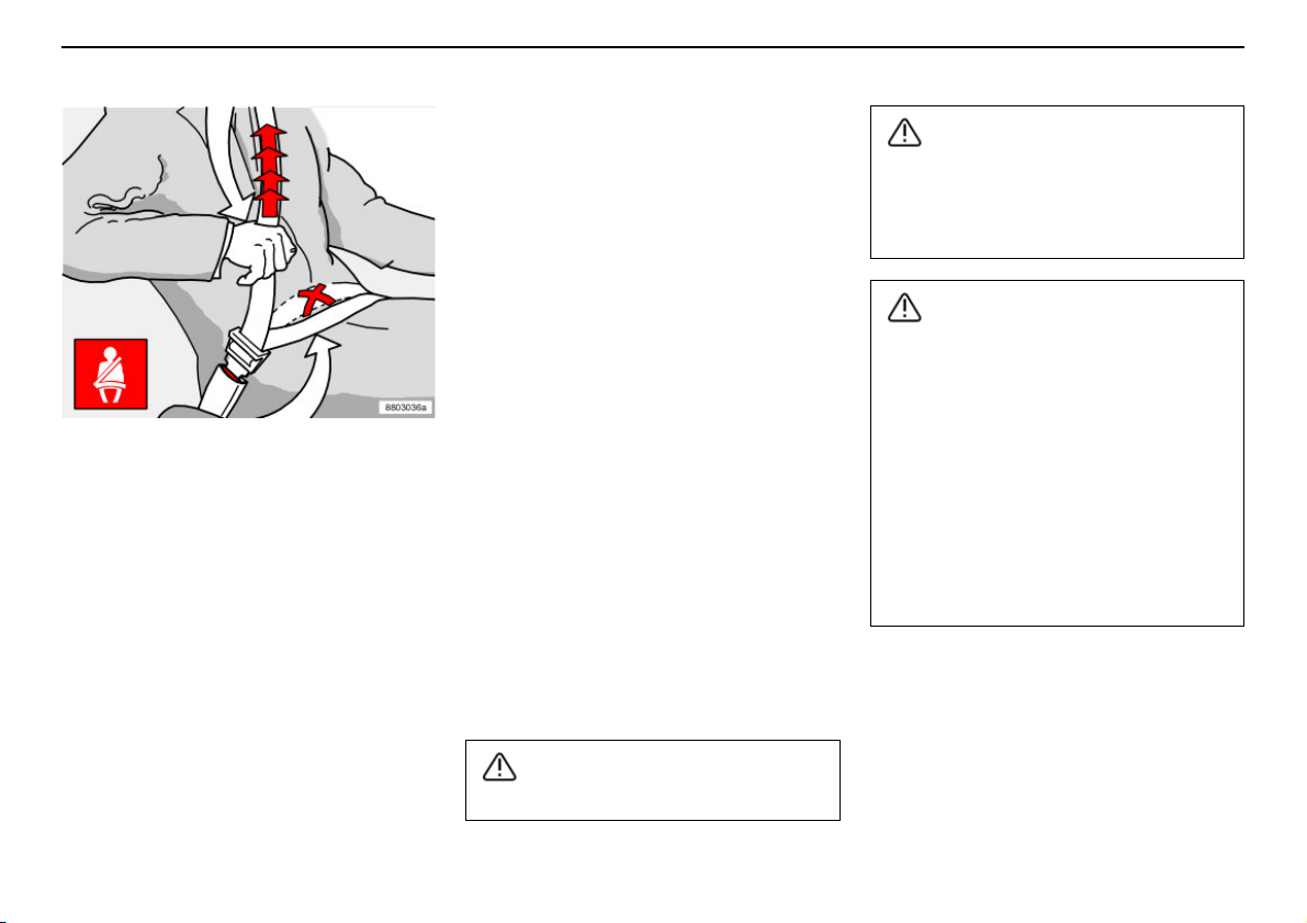
Tensioning the hip strap. The belt must be
positioned low down.
Always use a seatbelt
Heavy braking can have serious consequences if the seatbelts are not used. Ensure
that all passengers use their seatbelts. Otherwise, rear seat passengers may be thrown
forward against thebacks of the front seats in
a collision.
Putting on a seatbelt:
– Pull the belt out slowly and secure it by
pressing the buckle into the lock. A loud
"click" indicates that the belt has locked.
Releasing the belt:
– Press the red lock button and let the belt
retract. If the belt does not retract fully,
feed the belt in by hand so that it does not
hang lose.
The belt locks and cannot be withdrawn:
• if it is pulled out too quickly
• during braking and acceleration
• if the car leans heavily.
It is important that the belt lies against the
body so it can provide maximum protection.
Do not lean the backrest too far back. The
seatbelt is designed to protect in a normal
seating position.
Keep the following in mind:
• do not use clips or anything else that can
prevent the belt from fitting properly
• ensure the belt is not be twisted or
caught on anything
• the hip strap must be positioned low
down (not over the abdomen)
• tension the hip strap over the lap by
pulling the diagonal shoulder belt as illustrated.
The seatbelts and airbags interact. If a
seatbelt is not used or is used incorrectly,
this may diminish the protection provided
by the airbag in the event of a collision.
Never modify or repair the seatbelts yourself. Contact an authorised Volvo workshop.
If the belt has been subjected to a major
load, such as in a collision, the entire belt
must be replaced. Some of the protective
characteristics of the belt may have been
lost, even if it appears to be undamaged.
Replace the seatbelt if the belt is worn or
damaged. The new seatbelt must be typeapproved and intended for installation in
the same position as the replaced belt.
10
Each belt is intended for one person only.
Page 12
Seatbelts
Seatbelt reminder
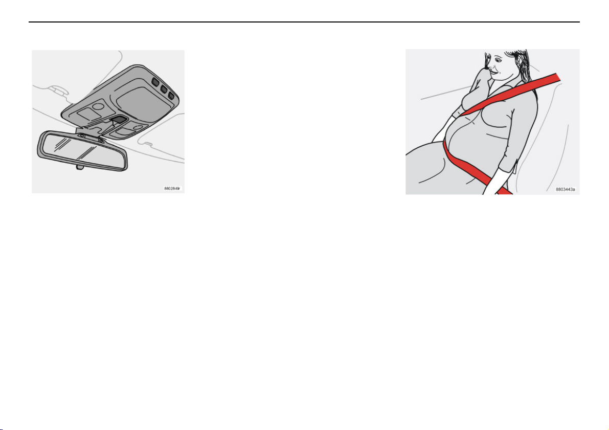
The seatbeltwarning symbol in the combined
instrument panel and above the rearview
mirror comes on until the driver and front seat
passenger buckle their seatbelts. The seatbelt reminder switches off after 6 seconds if
speed is below 10 km/h. If the driver or front
seat passenger have not buckled their seatbelts, the reminder switches on again when
the speed exceeds 10 km/h and switches off
if the speed drops below 5 km/h.
If the seatbelt is released, the function reactivates when speed exceeds 10 km/h.
NOTE! The seatbelt reminder is intended for
an adult sitting in the front seat. If a belt-fitted
child seat is fitted in the front seat, the
seatbelt reminder does not switch on.
Seatbelts and pregnancy
The seat belt should always be worn during
pregnancy. But it is crucial that it be worn in
the correct way. The diagonal section should
wrap over the shoulder then be routed
between the breasts and to the side of the
belly. The lap section should lay flat over the
thighs and as low as possible under the belly.
It must never be allowed to ride upward.
Remove all slack from the belt and insure that
it fits close to the body without any twists.
As a pregnancy progresses, pregnant drivers
should adjust their seats and steering wheel
such that they can easily maintain control of
the vehicle as they drive (which means they
must be able to easily operate the foot pedals
and steering wheel). Within this context, they
should strive to position theseat with aslarge
a distance as possible between their belly
and the steering wheel.
Safety
Seatbelts and pregnancy.
11
Page 13
Safety
Seatbelts
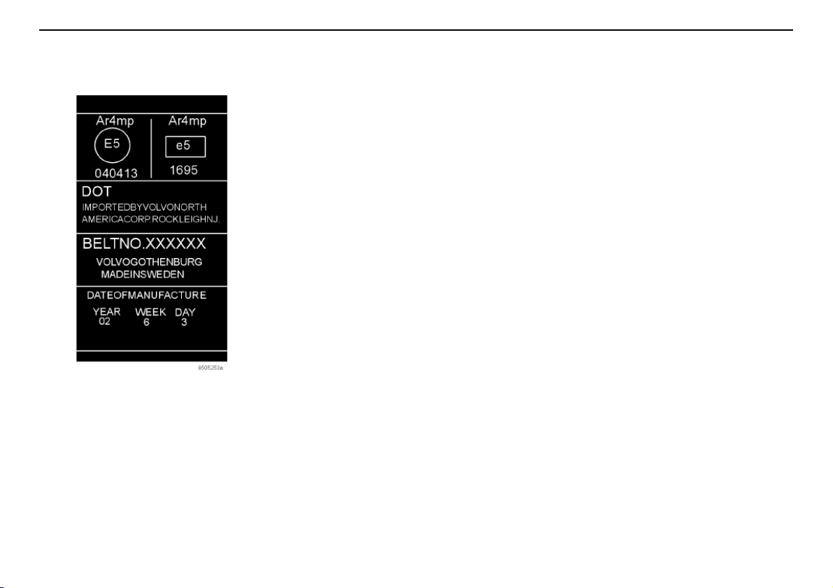
Label on seatbelts with seatbelt tensioner.
Seatbelt tensioner
All the seatbelts (except the centre rear belt)
are equipped with belt tensioners. A mechanism in the belt tensioner tightens the belt
around the body in the event of a sufficiently
violent collision. This provides more effective
restraint for passengers.
12
Page 14
Airbag system
WARNING!
Warning symbol in combined
instrument panel
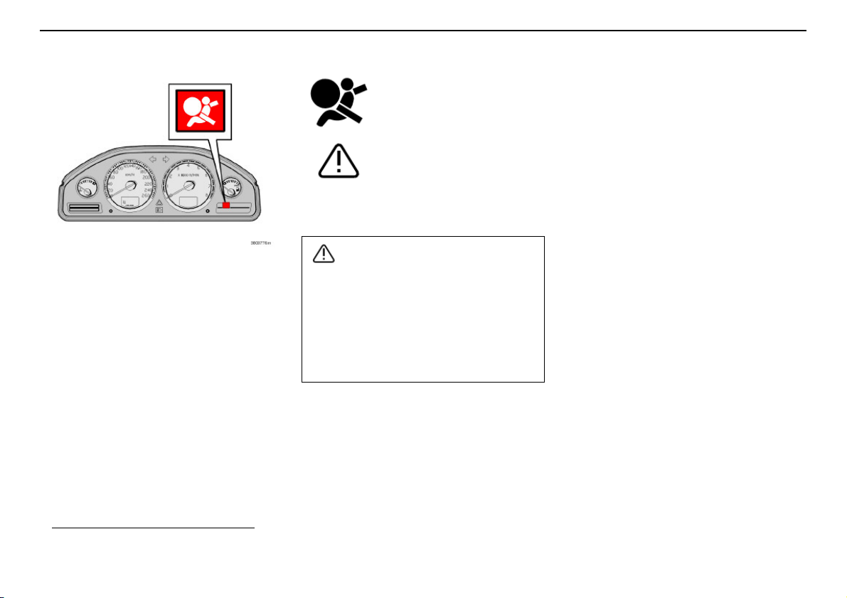
The Airbag system1is monitored continuously by the control module and there is a
warning lamp in the combined instrument
panel. This lamp comes on when the ignition
key is turned to position I, II or III. The
symbol goesout after about seven seconds if
the Airbag system
1
is working correctly.
Safety
As well as the warning
symbol, a message appears in
the information display. If the
warning symbol malfunctions,
the warning triangle comeson
and the message SRS
AIRBAG SERVICE URGENT
appears in the display.
Contact an authorised Volvo
workshop immediately.
If the warning symbol for the Airbag system remains on or comes on while driving,
it means that the Airbag system is not
functioning fully. The symbol can indicate
a fault in the seatbelt buckle, SIPS, SRS
or IC system. Contact an authorised Volvo
workshop immediately.
1. Includes SRS and seatbelt tensioner,
SIPS and IC.
13
Page 15
Safety
WARNING!
WARNING!
WARNING!
Airbags (SRS)
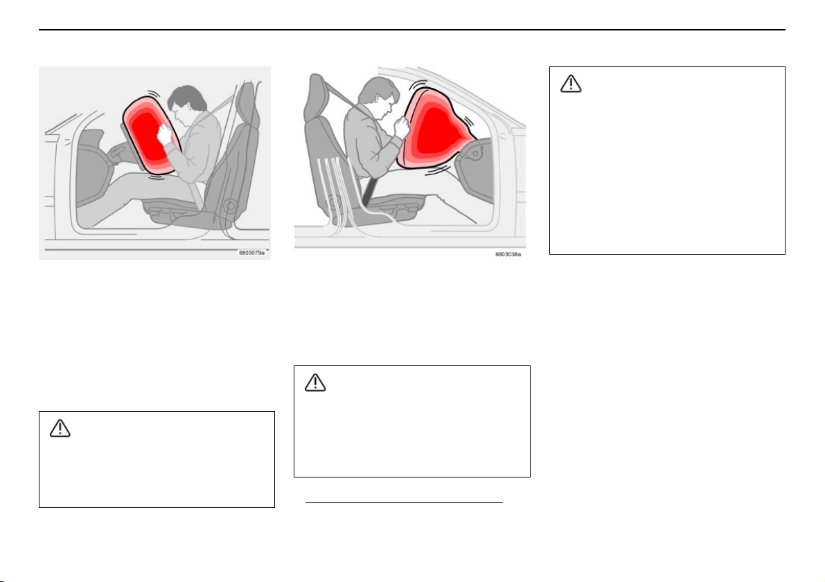
Airbag (SRS) on the driver’s side
The car has an SRS airbag (Supplemental
Restraint System) in the steering wheel to
supplement the protection afforded by the
seatbelt. This airbag is fitted intothe centre of
the steering wheel. The steering wheel is
marked SRS AIRBAG.
The seatbelts and airbags interact. If a
seatbelt is not used or is used incorrectly,
this may diminish the protection provided
by the airbag in the event of a collision.
14
Passenger airbag (SRS)
The passenger airbag1is fitted behind a
panel above the glovebox. This panel is
marked SRS AIRBAG
To minimise the risk of injury if the airbag
deploys, passengers must sit as upright
as possible with their feet on the floor and
backs against the backrest. Seatbelts
must be secured.
1. Not all cars have a passenger airbag
(SRS). This can be unselected when
the car is ordered.
Never place a child in a child seat or on a
booster cushion in the front seat if the airbag (SRS) is activated1.
Never allow a child to stand or sit in front
of the front passenger seat.
No one shorter than 140 cm should sit in
the front passenger seat if the airbag
(SRS) is activated.
Failure to follow the advice given above
can endanger the life of the child.
1. For information on activated/deactivated
airbag (SRS) see page 17.
Page 16
Airbags (SRS)
WARNING!
Safety
Repairs must only be performed by an
authorised Volvo workshop.
Any interference in the system could
cause malfunction and serious injury.
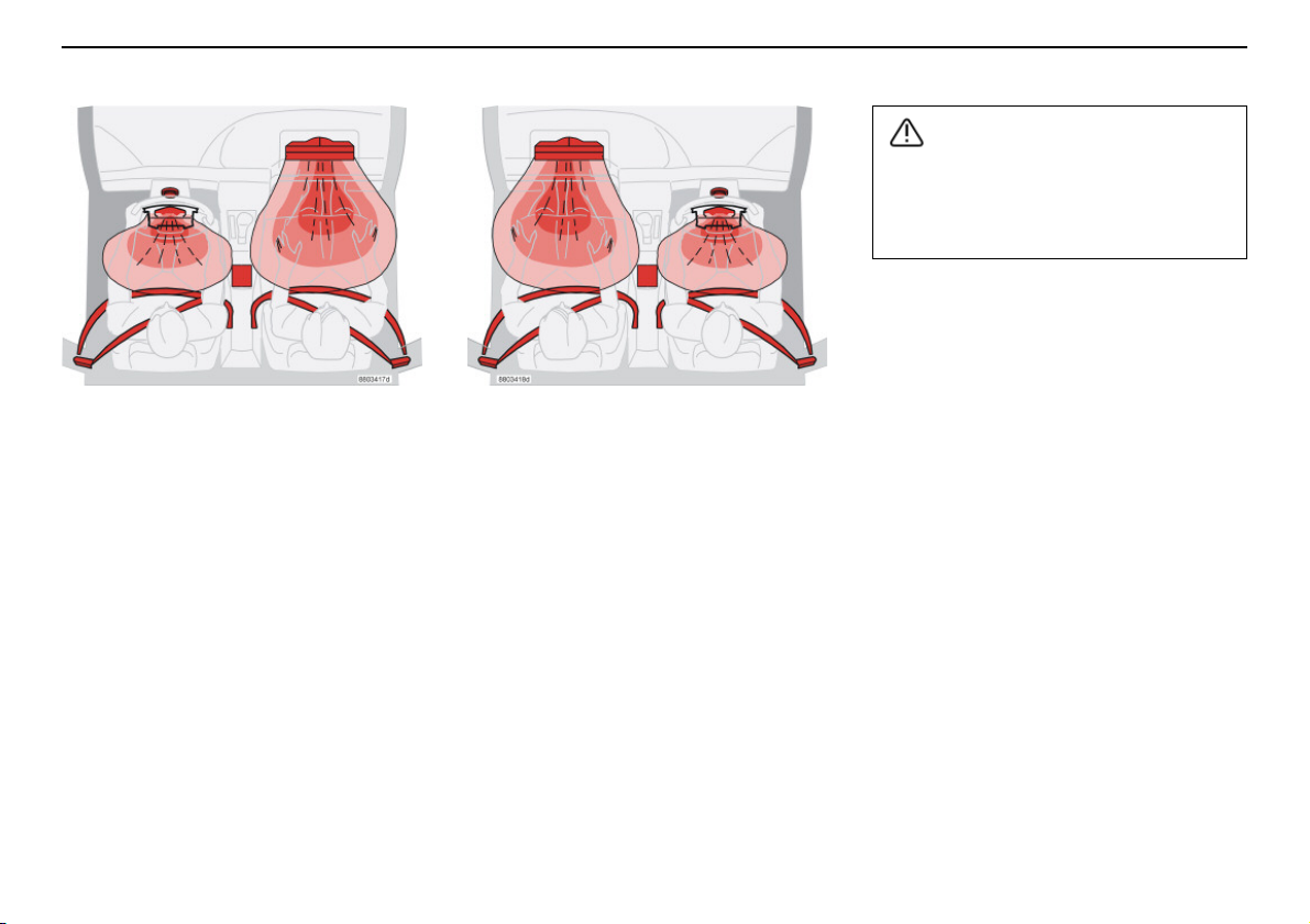
SRS system, left-hand drive.
SRS system
The airbag is equipped with a gas generator.
A sufficiently violent collision trips sensors
and ignites the gas generator, inflating the
airbag with hot gas. To cushion the impact,
the airbag deflates when compressed. When
this occurs, smoke escapes into the car. This
is completely normal. The entire process,
including inflation and deflation of the airbag,
occurs within tenths of a second.
SRS system, right-hand drive.
NOTE! The sensors react differently
depending on the course of the collision and
whether the seatbelts on the driver and
passenger side are used. It is therefore
possible that only one (or none) of the
airbags may inflate in a collision. The SRS
system senses the force of the collision on
the car and adapts accordingly so that one or
more airbags is deployed.
NOTE! The airbags have a function whereby
their capacities are adapted to the collision
force to which the vehicle is subjected.
15
Page 17
Safety
WARNING!
Airbags (SRS)
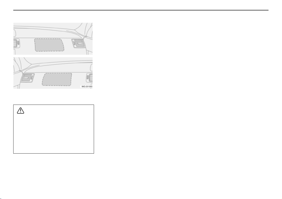
Location of the passenger airbag in left-hand
drive and right-hand drive cars.
Never interfere with SRS components in
the steering wheel or the panel above the
glovebox.
Objects and accessories must not be
positioned or glued on o r near the SRS
AIRBAG panel (above the glovebox) or in
the area affected by a deployed airbag.
16
Page 18
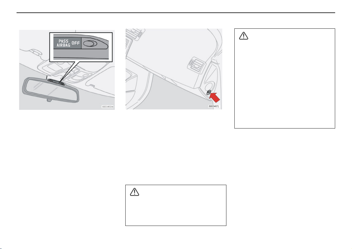
Activating/deactivating the airbag (SRS)
WARNING!
WARNING!
Indicator showing that the passenger airbag
(SRS) is deactivated.
PACOS (option)
The airbag (SRS) for the front passenger
seat can be deactivated using a switch. This
is necessary if a child seat is to be placed
there for example.
Indicator
A text message in the rearview mirror indicates that the passenger airbag (SRS) is
deactivated.
Switch for PACOS (Passenger Airbag Cut
Off Switch).
Activating/deactivating
The switch is located on the passenger end
of the dashboard and is accessible when the
passenger door is open. Check that the
switch is in the required position. Volvo recommends that that the ignition key is used to
change position. (Other items with a shape
similar to a key can be used).
Safety
Activated airbag (passenger seat):
Never place a child in a child seat or on a
booster cushion in the front passenger
seat when the airbag is activated. This
also applies to anyone shorter than
140 cm.
Deactivated airbag (passenger seat):
No one taller than 140 cm should ever sit
in the front passenger seat when the
airbag is deactivated.
Failure to follow the advice given above
can endanger life.
If the car is equipped with a front passenger airbag (SRS), but does not have
PACOS, the airbag will always be activated.
17
Page 19
Safety
WARNING!
Activating/deactivating the airbag (SRS)
Do not allow anyone to sit in the front passenger seat if the text message in the roof
panel indicates that the airbag (SRS) is
deactivated and the airbag warning symbol is displayed in the combined instrument panel. This indicates that there has
been a severe malfunction. Contact an
authorised Volvo workshop as soon as
possible.
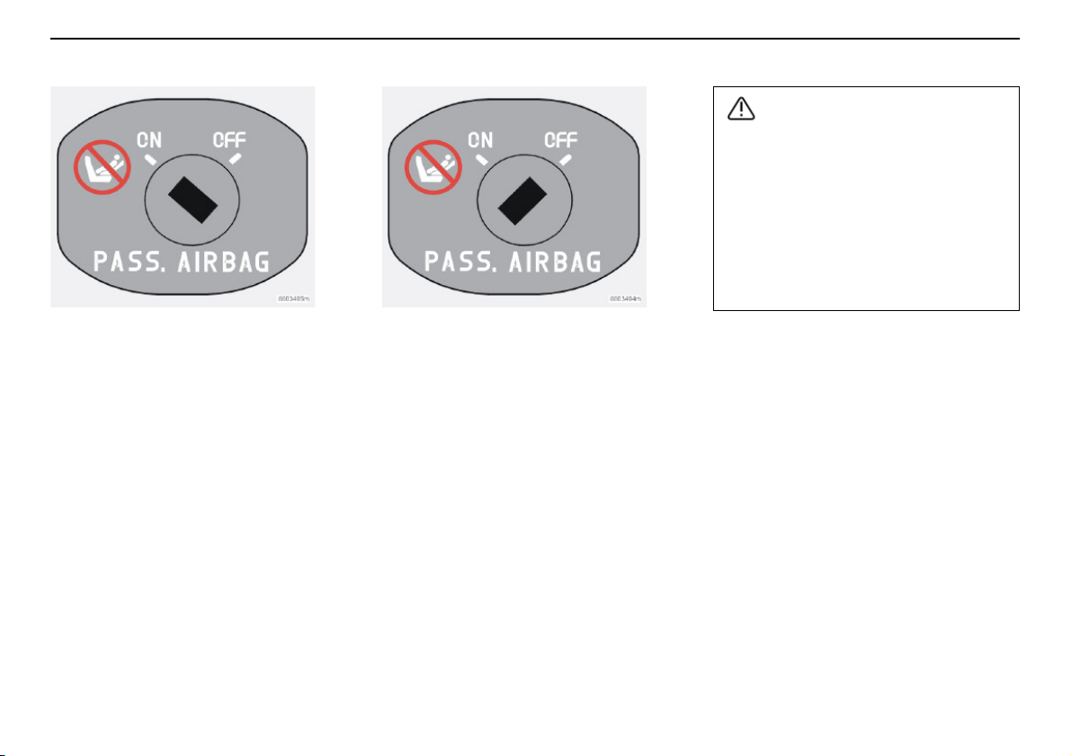
Switch for SRS in ON position.
Switch position
ON = Airbag (SRS) activated. With the
switch in this position, persons taller than
140 cm can sit in the front passenger seat,
but never children in a child seat or on a
booster cushion.
18
Switch for SRS in OFF position.
OFF = Airbag (SRS) is deactivated. With the
switch in this position, children in a child seat
or on a booster cushion can sit in the front
passenger seat, but never persons taller than
140 cm.
Page 20
Side airbags (SIPS bags)
WARNING!
WARNING!
WARNING!
WARNING!
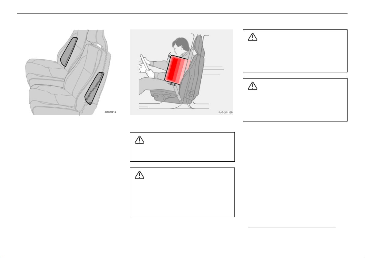
Side airbag locations
Side airbags – (SIPS bags)
A large proportion of the collision force is
transferred by the SIPS (Side Impact Protection System) to the floor, roof, beams, pillars,
and other structural parts of the body. The
side airbags on the driver’s and front passenger seats protect the chest area and are an
important part of the SIPS. The side airbags
are located in the front seat backrests.
Inflated side airbag
Side airbags are a supplement to the
SIPS system. Always wear a seatbelt.
Repairs must only be performed by an
authorised Volvo workshop.
Work on the SIPS system can cause
malfunction and result in serious personal
injury.
Safety
Do not put objects in the area between
the outside of the seat and the door panel,
since this area is required by the side
airbag.
Use only Volvogenuine car seat covers, or
seat covers approved by Volvo. Other
seat covers may impede the operation of
the side airbags.
Child seats and side airbags
The side airbag does not diminish the protection provided by the car to children seated in
a child seat or on a booster cushion.
A child seat or booster cushion can be
placed on the front passenger seat provided
that the car does not have an activated1passenger airbag.
1. For information on activated/deacti-
vated airbag (SRS) see page 17.
19
Page 21
Safety
Side airbags (SIPS bags)
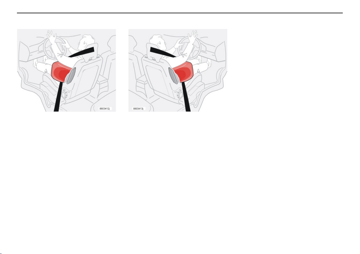
Left-hand drive.
SIPS bags
The side airbag is equipped with a gas generator. A sufficiently violent collision trips the
sensors and ignites the gas generator, inflating the side airbag. The airbag inflates
between the occupant and the door panel
and thereby cushions the initial impact while
deflating. The side airbag is only normally
deployed on the side of the collision.
20
Right-hand drive.
Page 22
Inflatable Curtain (IC)
WARNING!
WARNING!
WARNING!
Properties
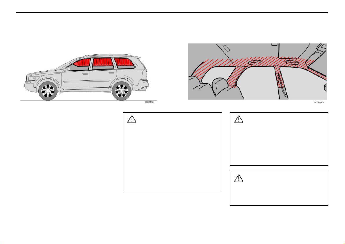
The inflatable curtain, IC (Inflatable Curtain),
is a supplement to the SIPS system. It is concealed in the headlining along both sides of
the roof and protects both front and rear seat
passengers. The inflatable curtain is activated by sensors in a sufficiently violent collision or if the car is at risk from overturning.
When deployed, the inflatable curtain
inflates. The inflatable curtain helps to prevent the driver and passengers from striking
their heads on the inside of the car during a
collision.
In the Volvo XC90, the inflatable curtains
have been developed to protect occupants in
the event of overturning. The inflatable curtain
also covers those travelling in the third row of
seats in the variant that seats seven.
Never hang or fasten anything on the roof
handles. The hook is only intended for
light outer garments (not for hard objects
such as umbrellas).
Do not screw or fit anything to the
headlining, door pillars or side panels.
This could compromise the intended
protection. Only use Volvo genuine parts
that are approved for placement in these
areas.
Safety
Do not load the car higher than 50 mm
under the top edge of the rear passenger
windows. Otherwise, the intended protection of the inflatable curtain, which is concealed in the headlining, may be compromised.
The inflatable curtain is a supplement to
the seatbelts.
Always use a seatbelt.
21
Page 23
Safety
WARNING!
WARNING!
WHIPS
Protection against whiplash
injury – WHIPS
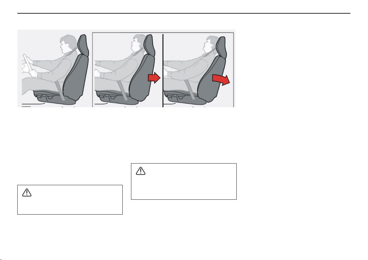
The WHIPS system (Whiplash Protection
System) consists of energy absorbing backrests and specially designed head restraints
for the front seats. The system is actuated by
a rear-end collision, where the angle and
speed of the collision, and the properties of
the colliding vehicle all have an influence.
The WHIPS system is a supplement to the
seatbelts. Always wear your seatbelt.
22
Properties of the seat
When the WHIPS system is deployed, the
front seat backrests fall backward to alter the
position of the driver and front seat passenger. This diminishes the risk of whiplash
injury.
Never modify or repair the seat or WHIPS
system yourself. Contact an authorised
Volvo workshop.
WHIPS system and child seats/
booster cushions
The WHIPS system does not diminish the
protection provided by the car to children
seated in a child seat or on a booster
cushion.
Correct seating position
For the best possible protection, the driver
and front seat passenger should sit in the
centre of the seat with as little space as possible between the head and the head
restraint.
Page 24
WHIPS
WARNING!
WARNING!
WARNING!
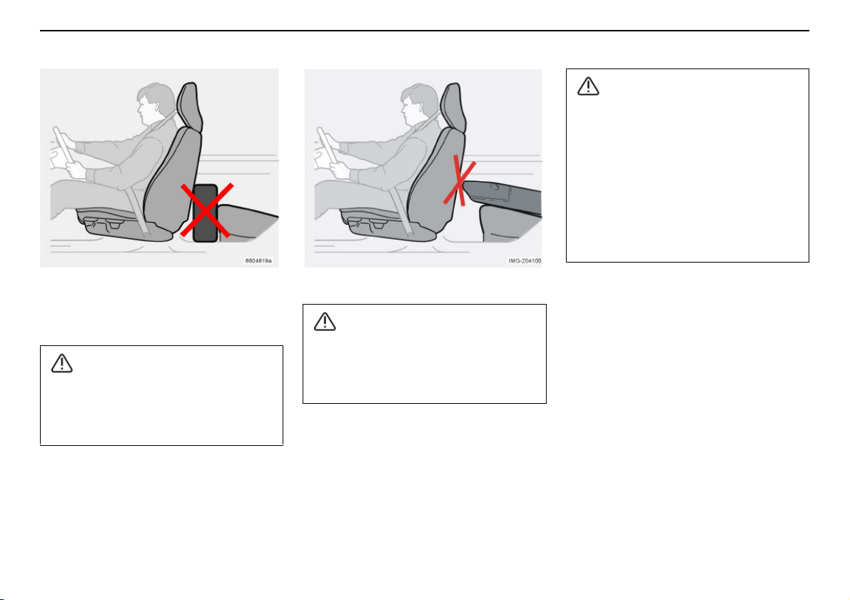
Do not obstruct the WHIPS
system
Do not squeeze rigid objects between the
rear seat cushion and the front seat backrest. Make sure you do not to obstruct the
function of the WHIPS system.
Safety
If a seat has been subjected to extreme
forces, such as due to a rear collision, the
WHIPS system must be checked by an
authorised Volvo workshop.
Part of the WHIPS system’s protective
capacity may have been lost even if the
seats appear to be undamaged. Contact
an authorised Volvo workshop to have the
system checked even after a minor rearend collision.
If a rear seat backrest is folded down, the
corresponding front seat must be moved
forward so that it does not touch the
folded backrest.
23
Page 25
Safety
WARNING!
ROPS
Volvo’s Roll-Over Protection System has
been designed to reduce the risk of the car
overturning and to provide the best possible
protection in the event of an accident.
The system consists of:
• A stabiliser system, RSC (Roll Stability
Control) that minimises the risk of
overturning during sudden evasive
manoeuvres or the like or if the car skids.
• Increased protection for the driver and
passengers through a reinforced body,
inflatable curtains and seatbelt tensioners
in all seats. See also page 12 and
page 21.
The RSC system uses a gyro sensor which
registers changes in the car’s lateral inclination angle. This information is then used to
calculate the risk for overturning. If a risk is
detected, the DSTC system is engaged,
engine speed is reduced and one or more
wheels are braked until the car returns to a
stable position.
For more information on the DSTC system,
see page 46 and page 124.
Under normal driving conditions, the RSC
system improves the car’s road safety, but
this must not be taken as a reason to
increase speed. Always follow the usual
precautions for safe driving.
24
Page 26
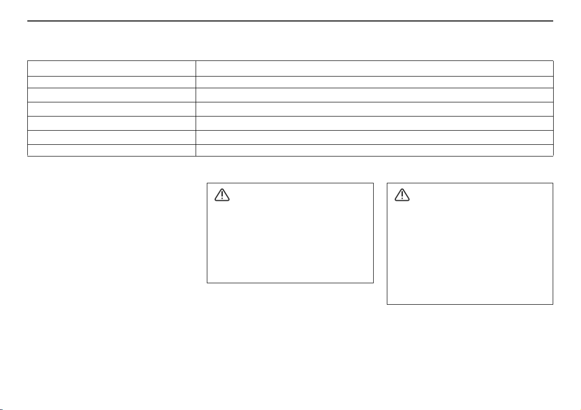
When are the safety systems activated?
WARNING!
WARNING!
System Triggered
Seatbelt tensioner In a frontal collision and/or side-impact accident.
Airbags (SRS)
Side airbags
Inflatable Curtain (IC)
WHIPS
RSC During sudden evasive manoeuvres or the like or if the car skids.
1. The bodywork of the car could be greatly deformed in a collision without airbag deployment. A number of factors such as the rigidity and weight of the
object hit, the speed of the car, the angle of the collision etc. affects how the different safety systems of the car are activated.
If the airbags have been deployed, the following is recommended:
• Have the car transported to an authorised
Volvo workshop. Do not drive with
deployed airbags.
• Have an authorised Volvo workshop
replace components in the car’s safety
system.
• Always contact a doctor.
NOTE! The SRS, SIPS, IC and belt tensioner
systems are deployed only once during a
collision.
In the event of a head-on collision
In the event of a side impact
In a side collision and/or overturning1.
In a rear-end collision1.
The Airbag control unit is located in the
centre console. If the centre console is
drenched with water or other liquid, disconnect the battery cables. Do not
attempt to start the car since the airbags
may deploy. Have the car transported to
an authorised Volvo workshop.
1
.
1
.
Never drive with deployed airbags. They
can make steering difficult. Other safety
systems may also be damaged. The
smoke and dust created when the airbags
are deployed can cause skin and eye irritation after intensive exposure. In case of
irritation, wash with cold water. The rapid
deployment sequence and airbag fabric
may cause friction and skin burns.
Safety
25
Page 27
Safety
Inspecting the airbags and inflatable curtains
Inspection intervals
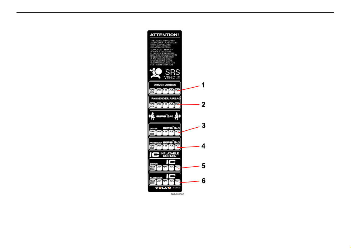
The decal on the door pillar(s) shows the
dates (year, month) when you should contact
an authorised Volvo workshop to inspect and,
if necessary, replace the airbags, belt tensioners and inflatable curtains. If you have
questions concerning the systems, contact
an authorised Volvo workshop.
1. Driver airbag
2. Front passenger airbag
3. Side airbag on the driver’s side
4. Side airbag on the passenger side
5. Inflatable curtain on the driver’s side
6. Inflatable curtain on the passenger side
26
This decal is located in the rear left door
opening.
Page 28
Child safety
Children should sit comfortably
and safely
The position of a child in the car and the
choice of equipment is dictated by the child’s
height and size, for more information, see
page 30.
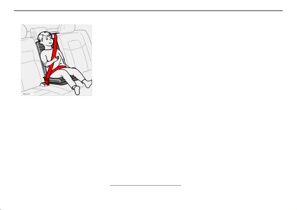
Children who are shorter than 150 cm must
be carried in adequate child protection.
NOTE! Regulations regarding the placement
of children in cars vary from country to
country. Check what laws apply.
Children of all ages and sizes must always sit
correctly secured in the car. Never allow a
child to sit on the knee of a passenger.
Volvo’s own child safety equipment is
designed for your car. Use Volvo genuine
equipment to best ensure that the mounting
points and attachments are correctly positioned and are sufficiently strong.
You may place:
• a child seat or booster cushion on the
front passenger seat, provided the
passenger airbag is not activated
• a rear-facing child seat in the rear seat
that uses the back of the front seat as
support.
1
Child seat and seatbelt reminder
If a rear-facing infant or child seat is placed in
the front seat and secured using the seatbelt,
the seatbelt reminder might not be activated.
Always check that the belt is locked before
driving off!
Safety
1. For information on activated/deactivated airbag (SRS) see page17.
27
Page 29
Safety
WARNING!
Child safety
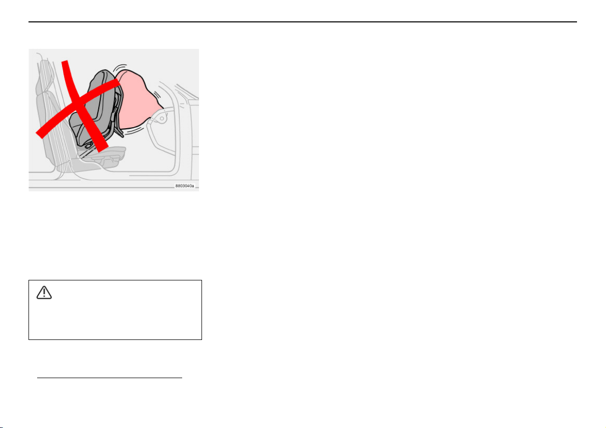
Child seats and airbags are not compatible.
Child seats and airbags
Always place a child in the rear seat if the
passenger airbag is activated
child seat on the front passenger seat may
suffer serious injury if the airbag deploys.
Persons shorter than 140 cm may only sit
in the front passenger seat if the passenger airbag is deactivated.
1
. A child in a
1. For information on activated/deactivated airbag (SRS) see page 17.
28
Page 30
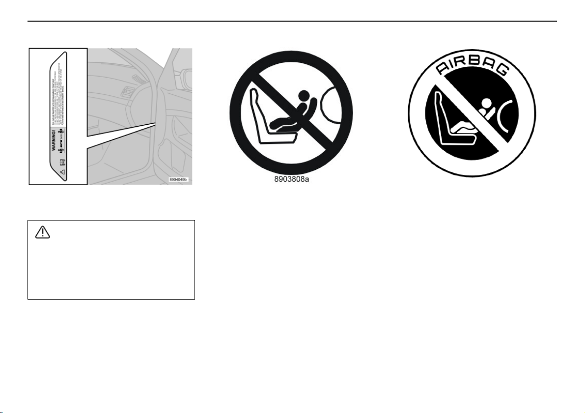
Child safety
WARNING!
Safety
Location of airbag decal in door opening on
front passenger side.
Never place a child in a child seat or on a
booster cushion in the front seat if the airbag (SRS) is activated. Failure to follow
this advice can endanger the life of the
child.
Decal located on dashboard end face. Decal located on dashboard end face.
(Australia only).
29
Page 31

Safety
Child safety
Placement of children in the car
Weight/age
<10 kg
Front passenger seat with activated
airbag (SRS)
Not suitable for this age group. Alternatives: Rear-facing child seat, secured with seatbelt and straps.
(0–9 months)
9–18 kg
Not suitable for this age group Alternatives: Rear-facing child seat, secured with seatbelt and straps.
(9–36 months)
15–36 kg
Not suitable for this age group. Booster cushion with or without backrest.
(3–12 years)
1. For information on activated/deactivated airbag (SRS) see page 17.
2. Suitable for certain child seats as listed in the specified type approval. Child seats may be vehicle-specific, limited, semi-universal or universal.
1
Front passenger seat without (or with deactivated
(SRS) (option)
Type approval: E503135
2
Rear-facing infant seat, secured with seatbelt.
Type approval: E5 03160
Rear-facing infant seat, secured in Isofix attachment.
Type approval: E5 03162
Type approval: E5 03135
2
2
2
Rear-facing child seat, secured with seatbelt.
Type approval: E5 03161
Rear-facing child seat, secured in Isofix attachment.
Type approval: E5 03163
2
2
Type approval: E5 03139
1
) airbag
30
Page 32

Child safety
Placement of children in the car
Safety
Weight/age
<10 kg
(0–9 months)
9–18 kg
(9–36 months)
15–36 kg
(3–12 years)
Second row of seats, outer seats
1
Alternatives: Rear-facing child seat, secured with seatbelt,
support legs and straps. Type approval: E5 03135
2
Rear-facing infant seat, secured with seatbelt and support
legs. Type approval: E5 03160
2
Rear-facing infant seat, secured with Isofix attachment and
support legs. Type approval: E5 03162
2
Alternatives: Rear-facing child seat, secured with seatbelt,
support legs and straps. Type approval: E5 03135
2
Rear-facing child seat, secured with seatbelt and support
legs. Type approval: E5 03161
2
Rear-facing child seat, secured with Isofix attachment and
support legs. Type approval: E5 03163
2
Booster cushion with or without backrest.
Type approval: E5 03139
2
Second row of seats,
centre seat
1
Rear-facing child seat,
secured with seatbelt,
support legs and straps.
Type approval:
E5 03135
2
Rear-facing child seat,
secured with seatbelt,
support legs and straps.
Type approval:
E5 03135
2
Alternatives: Booster
cushion with or without
backrest. Type approval:
E5 03139
2
Third row of seats in
cars seating seven.
Not suitable for this age
group.
Not suitable for this age
group.
Booster cushion with or
without backrest.
Type approval:
E5 03139
Integrated booster
cushion.
Type approval:
E5 03167
1. In cars seating seven, the seat row must be in its rearmost position when using a child seat.
2. Suitable for certain child seats as listed in the specified type approval. Child seats may be vehicle-specific, limited, semi-universal or universal.
3. Integrated and approved child safety equipment for this age group.
3
2
31
Page 33
Safety
WARNING!
WARNING!
Child safety
Check that:
• the seatbelt is locked
• the seatbelt is in contact with the child’s
body and is not slack or twisted, and that
the belt is positioned correctly across the
shoulder
• the lap belt is low over the pelvis for
optimum protection
• the belt does not touch the child’s throat
or lie below the shoulder
• carefully adjust the position of the head
restraint to suit the child
Integrated booster cushions
(option in cars seating five,
standard in cars seating seven)
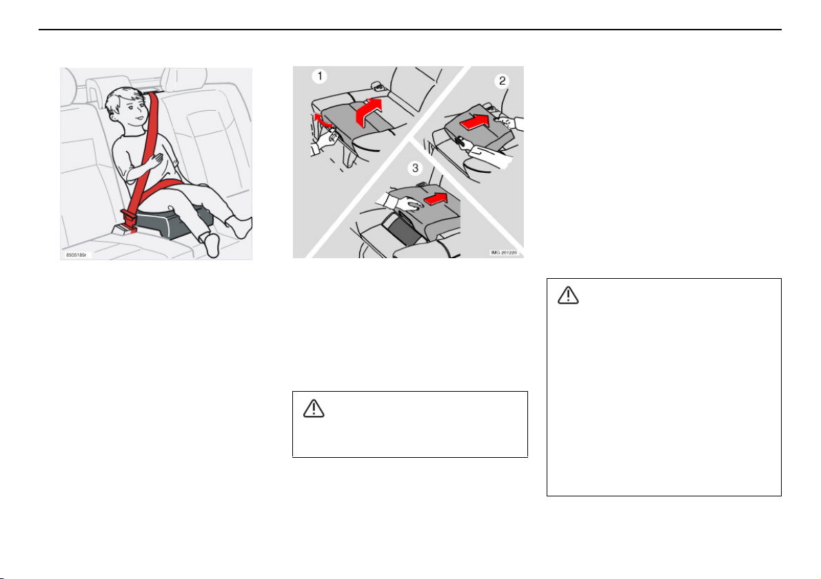
Volvo’s integrated booster cushion for the
outer rear seats is specially designed to provide optimum safety for children. Combined
with the regular seatbelts, the booster cushion is approved for children weighing
between 15 and 36 kg.
32
Raising the booster cushion
– Pull that handle to raise the booster
cushion (1).
– Grasp the cushion with both hands and
push it backwards (2).
– Push until it locks in place (3).
The booster cushion must be in the locked
position before the child is placed there.
Repair or replacement should only be performed by an authorised Volvo workshop.
Do not make any modifications or additions to the booster cushion.
If an integrated booster cushion has been
subjected to a major load, such as in
conjunction with a collision, the entire
booster cushion must be replaced. Even if
the booster cushion appears to be
undamaged, it may not afford the same
level of protection. The booster cushion
must also be replaced if it is heavily worn.
Page 34
Child safety
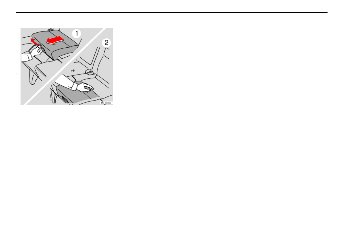
Lowering the booster cushion
– Pull the handle (1).
– Lower the seat and press until it locks (2).
NOTE! Remember to stow away the booster
cushion before lowering the rear seat
backrest.
Safety
33
Page 35
Safety
WARNING!
WARNING!
Child safety
Fitting a child seat
Volvo has child safety products that are
designed for and tested by Volvo.
Support cushions/child seats with steel
frames or another design that can lie
against the seatbelt release button must
not be used because they can cause accidental release of the seatbelt.
Do not allow the top of the child seat to
rest against the windscreen.
Never place the child seat in the front seat
if the car is equipped with an activated
front passenger airbag. If problems arise
when fitting child safety products, contact
the manufacturer for clearer instructions.
When using other products that are available
on the market, it is important to read thefitting
instructions included with the product.
• Do not attach the straps for the child seat
to the horizontal adjustment bar, springs,
rails or beams under the seat. Sharp
edges can damage the straps.
• Allow the back of the child seat to rest
against the dashboard. This applies to
cars without a passenger airbag, or
where the airbag is deactivated.
34
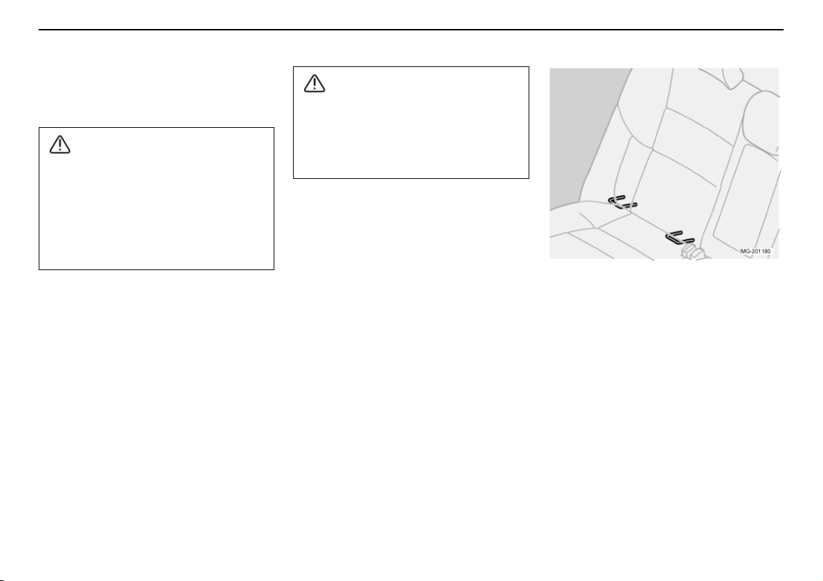
ISOFIX fixture system for child
seats (option)
The outer rear seats have ISOFIX attachment
points. Contact a Volvo dealer for further
information on child safety equipment.
Page 36

Child safety
Extra locking function in seatbelt
(ALR/ELR
The seatbelt in the centre of the second row
of seats has an extra locking function
(ALR/ELR) to help hold the belt taunt in order
to facilitate child seat installation.
When installing a child seat with the help of
the seatbelt:
• Secure the seatbelt in the child seat
following the instructions of the child seat
manufacturer.
• Pull out the entire seatbelt.
• Lock the belt by inserting the locking tab
in the buckle. A loud "click" indicates that
the belt is locked.
• Allow the seatbelt mechanism to retract
the belt while stretching it around the
child seat. A mechanical sound will be
audible from the seatbelt. This is normal.
This function is automatically deactivated
when the seatbelt is released from the buckle
and retracts back to its starting position.
If there are any problems with installation of
child safety products, contact the manufacturer for clearer installation instructions.
1
)
Safety
1. Automatic Locking Retractor/
Emergency Locking Retractor.
35
Page 37

Safety
36
Page 38

Instruments and controls
Overview, left-hand drive car 38
Overview, right-hand drive car 40
Driver’s door control panel 42
Combined instrument panel 43
Indicator and warning symbols 44
Information display 47
Switches in the centre console 49
Lighting panel 52
Left-hand stalk switch 53
Right-hand stalk switch 54
Trip computer 56
Cruise control 57
Parking brake, bonnet, electric socket, etc. 58
Power windows 61
Rearview mirror, door mirrors and side windows 63
Power sunroof (option) 65
37
Page 39
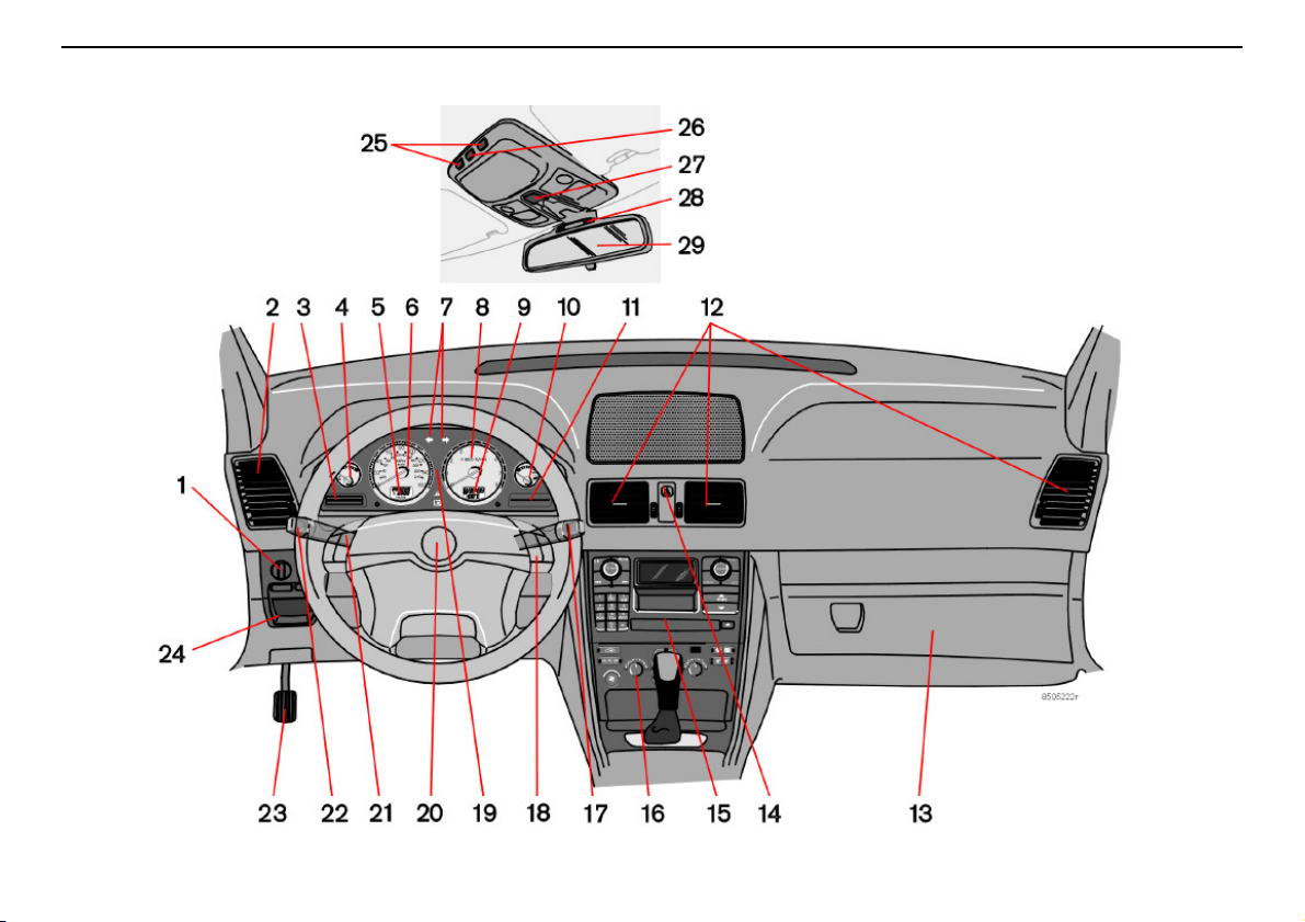
Instruments and controls
Overview, left-hand drive car
38
Page 40

Overview, left-hand drive car
Instruments and controls
1. Lighting panel .........................................................................page 52
2. Air vent......................................................................................page 69
3. Display......................................................................................page 47
4. Temperature gauge................................................................page 43
5. Odometer, trip odometer, cruise control...........................page 43
6. Speedometer ..........................................................................page 43
7. Direction indicators................................................................page 43
8. Tachometer..............................................................................page 43
9. Outside temperature, clock, gear position .......................page 43
10. Fuel gauge...............................................................................page 43
11. Indicator and warning symbols ...........................................page 44
12. Panel vents ..............................................................................page 69
13. Glovebox..................................................................................page 86
14. Hazard warning flashers.......................................................page 51
15. Audio system........................................................................ page 208
16. Climate control ............................................................... page 70, 73
17. Windscreen wipers................................................................page 54
18. Keypad for telephone/audio..............................................page 200
19. Combined instrument panel ................................................page 43
20. Horn .......................................................................................................–
21. Cruise control .........................................................................page 57
22. Direction indicators, dipped-main beam switch,
READ button ...........................................................................page 53
23. Parking brake ..........................................................................page 58
24. Parking brake release............................................................page 58
25. Switches, reading lamps......................................................page 83
26. Interior lighting........................................................................page 83
27. Sunroof control.......................................................................page 65
28. Seatbelt reminder ..................................................................page 11
29. Rearview mirror.......................................................................page 63
39
Page 41
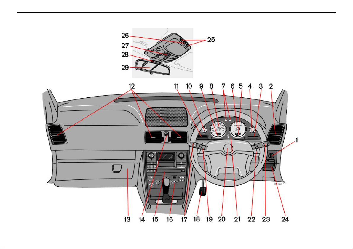
Instruments and controls
Overview, right-hand drive car
40
Page 42

Overview, right-hand drive car
Instruments and controls
1. Lighting panel .........................................................................page 52
2. Air vent......................................................................................page 69
3. Indicator and warning symbols ...........................................page 44
4. Fuel gauge...............................................................................page 43
5. Outside temperature, clock, gear position .......................page 43
6. Tachometer..............................................................................page 43
7. Direction indicators................................................................page 43
8. Speedometer ..........................................................................page 43
9. Odometer, trip odometer, cruise control...........................page 43
10. Temperature gauge................................................................page 43
11. Display......................................................................................page 47
12. Panel vents ..............................................................................page 69
13. Glovebox..................................................................................page 86
14. Hazard warning flashers.......................................................page 51
15. Audio system........................................................................ page 208
16. Climate control ............................................................... page 70, 73
17. Direction indicators, dipped-main beam switch,
READ button ...........................................................................page 53
18. Parking brake ..........................................................................page 58
19. Cruise control .........................................................................page 57
20. Horn .......................................................................................................–
21. Combined instrument panel ................................................page 43
22. Telephone/Audio keypad................................................... page 200
23. Windscreen wipers................................................................page 54
24. Parking brake release............................................................page 58
25. Switches, reading lamps......................................................page 83
26. Interior lighting........................................................................page 83
27. Sunroof control.......................................................................page 65
28. Seatbelt reminder ..................................................................page 11
29. Rearview mirror.......................................................................page 63
41
Page 43
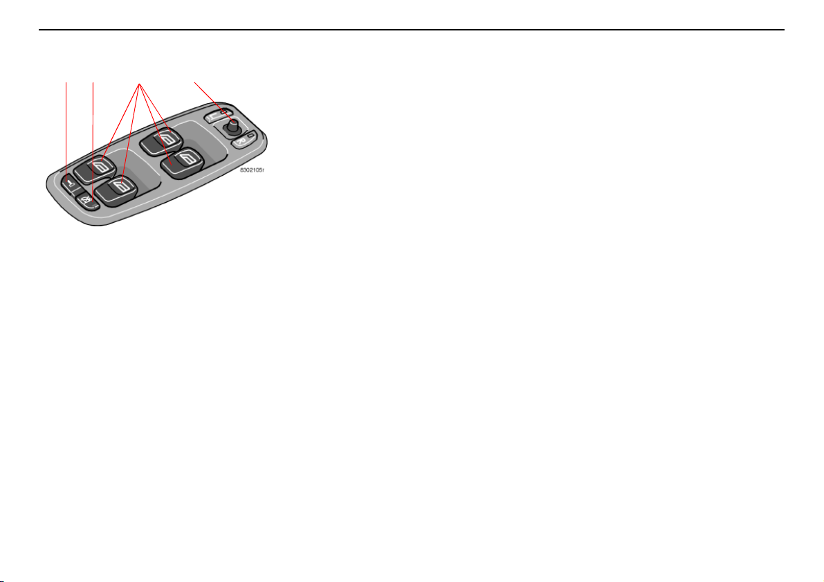
Instruments and controls
1 2 3 4
Driver’s door control panel
1. Lock button for all doors
2. Blocking power windows in the rear
doors
3. Power window controls
4. Door mirror control
42
Page 44
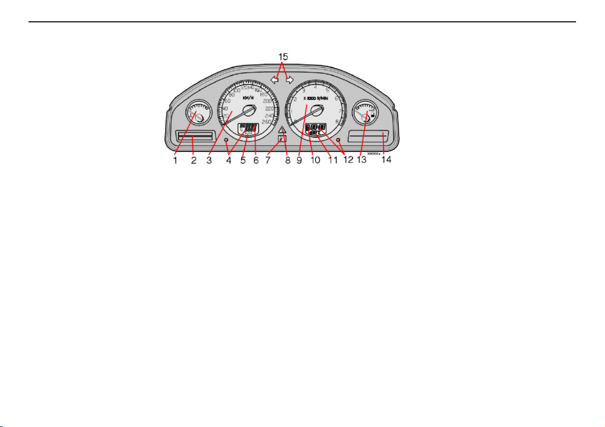
Combined instrument panel
Instruments and controls
1. Temperature gauge
Displays the temperature of the engine
cooling system. If the temperature is abnormally high and the needle enters the red
zone, a message is shown in the display.
Bear in mind that extra lampsin front of theair
intake reduce the cooling capacity at high
outside temperature and high engine loads.
2. Display
The display shows information and warning
messages.
3. Speedometer
Shows the speed of the car.
4. Trip odometer, T1 and T2
The trip odometers are used for measuring
short distances. The right-hand digit displays
tenths of a kilometre. Press the button for
more than 2 seconds to reset. Change
between trip odometers by briefly pressing
the button once.
5. Cruise control indicator
See page 57.
6. Odometer
The odometer indicates the total distance the
car has travelled.
7. Main beam, On/Off
8. Warning symbol
If a fault arises, the symbol lights up and a
message is shown in the display.
9. Tachometer
Indicates engine speed in thousands of
revolutions per minute (RPM). Do not allow
the needle of the tachometer to enter the red
field.
10. Automatic gearbox indicator
The selected gearshift programme is
displayed here.
11. Outside temperature gauge
Displays outside temperature. When the
temperature lies between +2 °C and –5 °C, a
snowflake symbol is shown in the display.
This symbol serves as a warning for slippery
road surfaces.
When thecar is or was stationary, the outside
temperature gauge may read a higher
reading than actual.
12. Clock
Turn the button to set the clock.
13. Fuel gauge
When the lamp in the instrument panel lights,
approximately 8 litres of usable fuel remain in
the tank.
14. Indicator and warning symbols
15. Direction indicators – left/right
43
Page 45
Instruments and controls
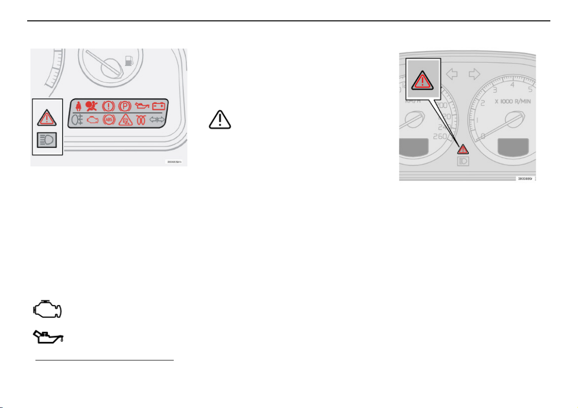
Indicator and warning symbols
Indicator and warning symbols
All indicator and warning symbols1light up
when the ignition key is turned to position II
before starting. This is to check that the
symbols/lights are working. When the engine
starts, all the symbols should go out except
the handbrake symbol, which extinguishes
when the handbrake is released.
If the engine does not start
within five seconds, all symbols
extinguish except the symbols
for afault in the car’s emissions
system and for low oil
pressure. Certain symbols may have no
function, depending on the car’s specifications.
Warning symbol in the centre of
the instrument panel
This symbolis lit with a red or amber
glow depending on the severity of
the fault.
Red symbol
– Stop the car. Read the message in the
display.
Symbol and message text are visible until the
fault has been rectified.
Yellow symbol
– Read the message in the display.
Remedy!
The message text is cleared using the READ
button, see page 47, or disappears automatically after 2 minutes.
NOTE! When the message text "TIME FOR
REGULAR SERVICE" is shown, the symbol
lamp and message text are cleared using the
READ button, or disappear automatically
after 2 minutes.
1. With certain engine variants the
symbol for low oil pressure is not lit.
44
Page 46
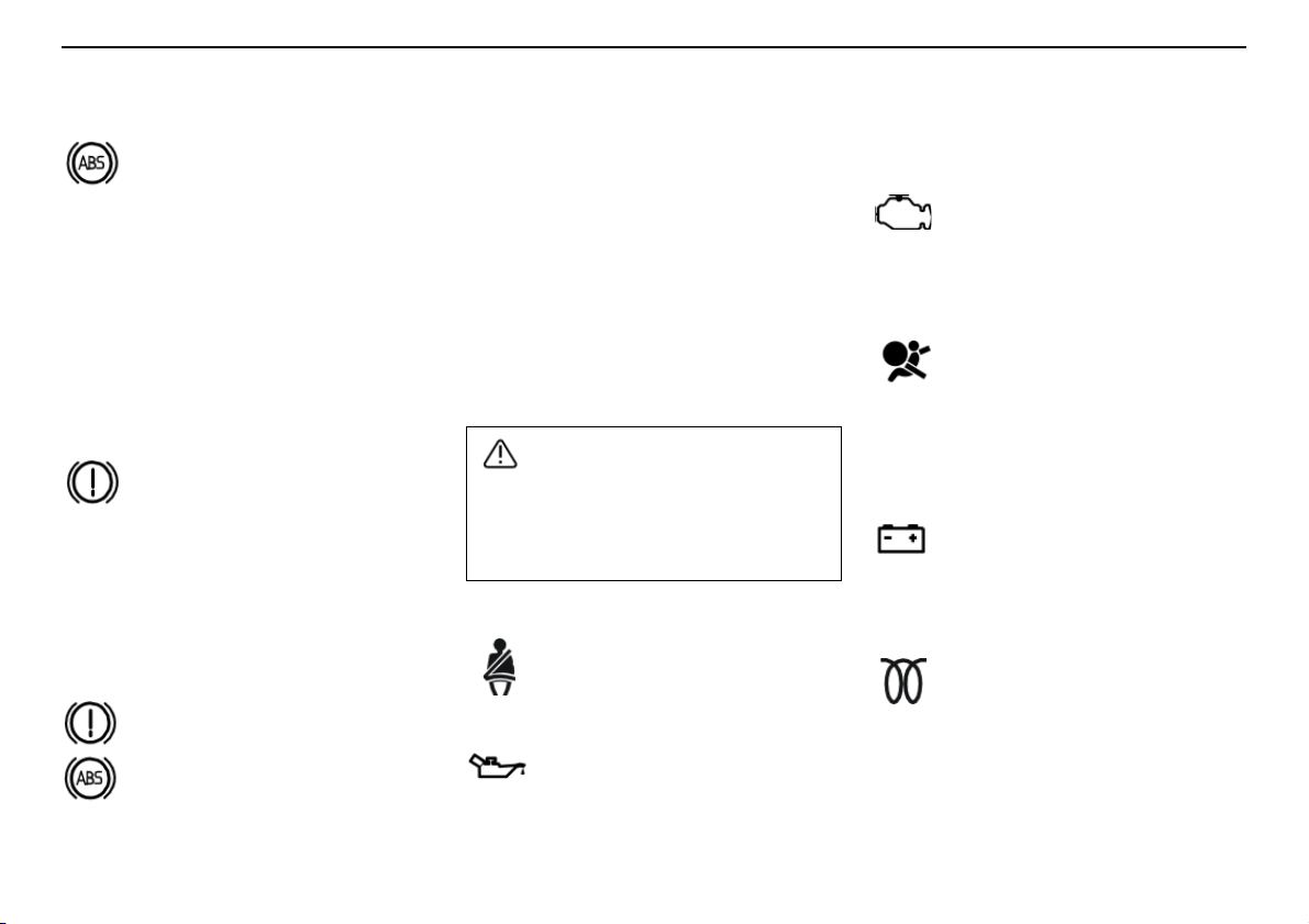
Indicator and warning symbols
WARNING!
Instruments and controls
ABS fault
If the ABS symbol lights, the ABS
system is not functioning. The car’s
normal braking system continues to
work, but without the ABS function.
– Stop the car in a safe place and switch off
the engine. Restart the engine.
– If the warning symbol goes out, continue
driving. It was an indicator error.
– If the warning symbol remains lit, drive to
an authorised Volvo workshop to have the
ABS system checked.
Fault in brake system
If the BRAKE symbol lights, the
brake fluid level may be too low.
– Stop the car in a safe place and check the
brake fluid reservoir level.
If the reservoir level is below MIN the car
should not be driven further. Have it towed to
an authorised Volvo workshop to have the
brake system checked.
If the BRAKE and ABS warning
symbols light at the same time, there
may be a problem in the brake force
distribution.
– Stop the car in a safe place and
switch off the engine. Restart the
engine.
• If both symbols go out, it was an indicator
error.
• If the warning symbols remain lit, check
the brake fluid reservoir level.
• If the reservoir level is below MIN, the car
should not be driven further. Have it
towed to an authorised Volvo workshop
to have the brake system checked.
• If the brake fluid level is normal and the
lamps remain lit, carefully drive the car to
the nearest authorised Volvo workshop to
have the brake system checked.
If the BRAKE and ABS warning symbols
light at the same time, there is a risk that
the rear end will have a tendency to slide
during heavy braking.
Seatbelt reminder
The lamp remains lit until the driver
and front seat passenger put on
their seatbelts.
Low oil pressure
If the lamp lights while driving,
engine oil pressure is too low. Stop
the engine immediately and check
the oil level. If the lamp lights but the
oil levelis normal, stopthe car and contact an
authorised Volvo workshop.
Fault in car’s emissions system
Contact an authorised Volvo
workshop to have the system
checked.
Fault in SRS
If a fault in the SRS system is
detected the warning symbol will
remain lit or light up while driving.
Drive to an authorised Volvo
workshop to have the system
checked.
Alternator not charging
If this lamp lights while driving, there
is probably a fault in the electrical
system. Contact an authorised
Volvo workshop.
Engine preheater (diesel)
This lamp lights to indicate that the
engine is being preheated. You can
start the car when the lamp goes
out. Applies to cars with diesel
engines only.
45
Page 47
Instruments and controls
WARNING!
Indicator and warning symbols
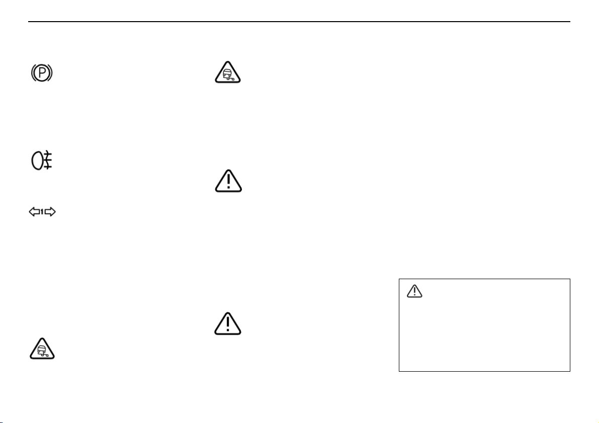
Parking brake applied
The lamp comes on when the
parking brake is depressed. Always
depress the parking brake to the
bottom position.
NOTE! The lamp comes on irrespective of
how hard the parking brake is depressed.
Rear fog lamp
This lamp lights when the fog lamp
is on.
Trailer indicator lamp
Flashes when the direction
indicators of the car and trailer are
used. If the lamp does not flash,one
of the direction indicators on the trailer or car
is defective.
Stability system and DSTC
The DSTC system contains several different
functions that are described in more detail on
page 124.
The symbol lights and goes out again
after approx. two seconds
The symbol is lit for a system check
when the car is started.
The symbol flashes
The SC function acts to prevent the
car’s drive wheels from spinning.
The TC function acts to improve the
car’s traction.
The AYC function acts to prevent skidding.
The RSC function acts to prevent
overturning.
The warning symbol shines with a
steady amber glow
TRACTION CONTROL
TEMPORARILY OFF is shown on
the information display together
with the symbol.
The TC function has been temporarily
suppressed because the brake temperature
is too high.
Automatic reactivation of the function takes
place when the brake temperature has
returned to normal.
The warning symbol shines with a
steady amber glow
ANTI-SKID SERVICEREQUIRED is
shown on the information display
together with the symbol.
The DSTC system has been switched off
because of a fault.
– Stop the car in a safe place and turn off
the engine.
– Restart the engine.
If the warning symbol remains lit, drive to an
authorised Volvo workshop to have the
system checked.
Fault in DSTC system
If the warning symbol lights and shines with a
constant glow even though you did not
switch off the system, it indicates a fault in
one of the systems. The text "ANTI-SKID
SERVICE REQUIRED" is shown in the
display.
– Stop the car in a safe place and switch off
the engine. Restart the engine.
• If the warning symbol goes out, the fault
was temporary and it is not necessary to
visit a workshop.
• If the warning symbol remains lit, drive to
an authorised Volvo workshop to have the
system checked.
Under normal driving conditions, the
DSTC system improves the car’s road
safety, but this should not be taken as a
reason to increase speed. Always follow
the usual precautions for safe cornering
and driving on slippery surfaces.
46
Page 48
Information display
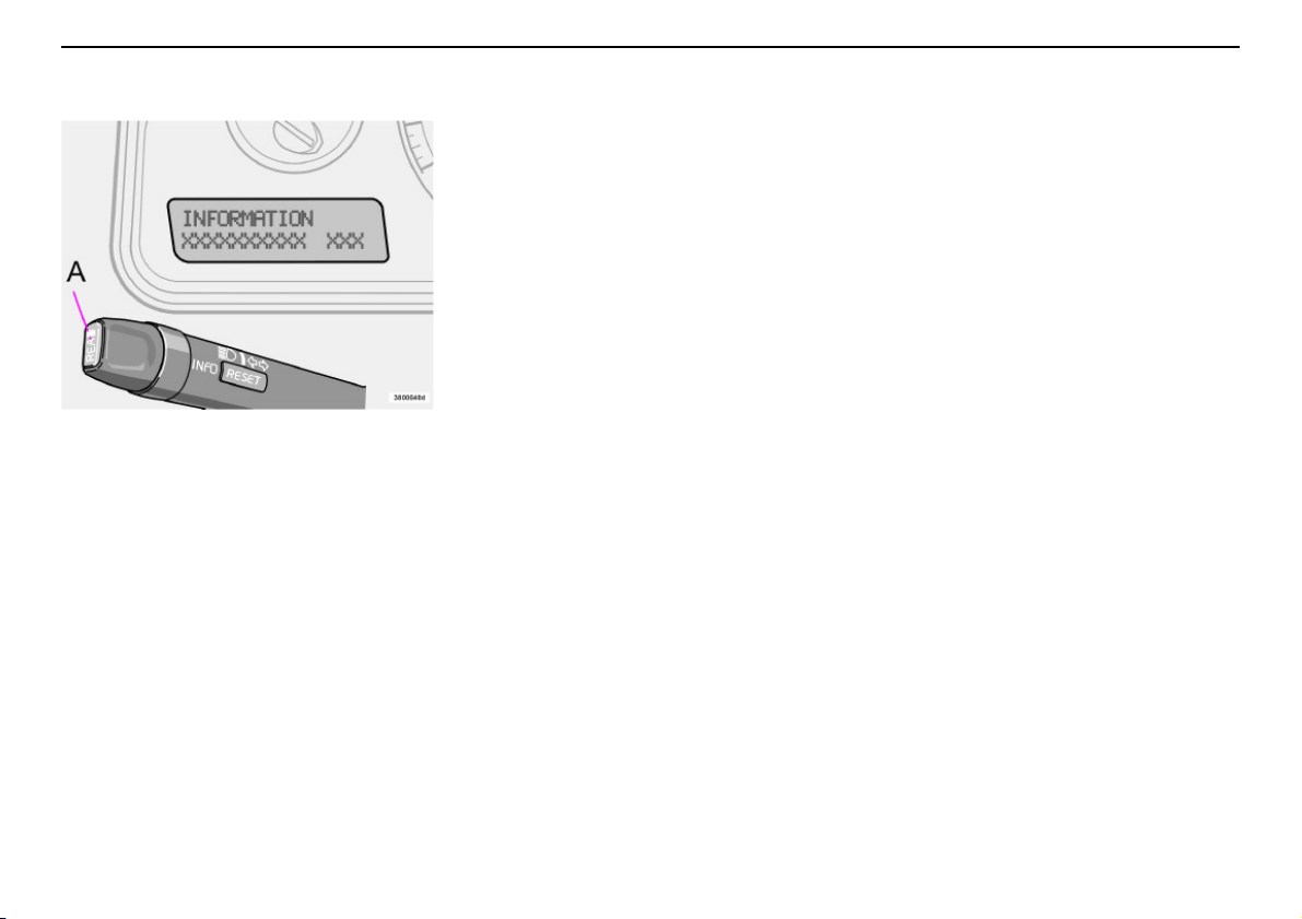
Messages on the display
Any warning or indicator symbol that appears
is accompanied by a message in the display.
Once you have read and understood the
message, press the READ button (A).
Messages which have been read are cleared
from the display and stored in the car’s
memory. Fault messages will remain in the
memory until the fault has been remedied.
Very serious fault messages cannot be
erased from the display. They remain in the
display until the fault is remedied.
Messages stored in the memory can be read
again. Press the READ button (A) to see
stored messages. Scroll through the
Instruments and controls
messages stored in the memory by pressing
the READ button. Press the READ button to
return read messages to the memory.
If a warning message interrupts when you are
in the trip computer menus or wish to use the
telephone, you must first acknowledge the
message by pressing the READ button (A).
47
Page 49

Instruments and controls
Information display
Message Specification
STOP SAFELY Stop and switch off the engine. Serious risk of damage.
STOP ENGINE Stop and switch off the engine. Serious risk of damage.
SERVICE URGENT Take your car in for service immediately.
SEE MANUAL Consult your owner’s manual.
SERVICE REQUIRED Take your car in for service as soon as possible.
FIX NEXT SERVICE Have your car checked at the next service interval.
TIME FOR REGULAR SERVICE When this message is shown, the car is due for a service. When the message is displayed is
affected by the distance travelled, number of months since last service and engine running
time.
OIL LEVEL LOW
OIL LEVEL LOW
OIL LEVEL LOW
OIL LEVEL LOW
1
– FILL OIL
2
– STOP SAFELY
2
– STOP ENGINE
2
– SEE MANUAL
SOOT FILTER FULL – SEE MANUAL
1. Displayed together with yellow warning triangle.
2. Displayed together with red warning triangle.
3. Only applies to engine variants with oil level sensor.
3
Low engine oil level. Check and remedy as soon as possible. See page 174 for more
information.
3
3
Low engine oil level. Stop the car safely and check the oil level. See page 174.
Low engine oil level. Stop the car safely, switch off the engine and check the oil level.
See page 174.
3
Low engine oil level. Stop the car safely, switch off the engine and check the oil level.
See page 174.
1
Diesel particle filter requires regeneration. See page 115.
48
Page 50
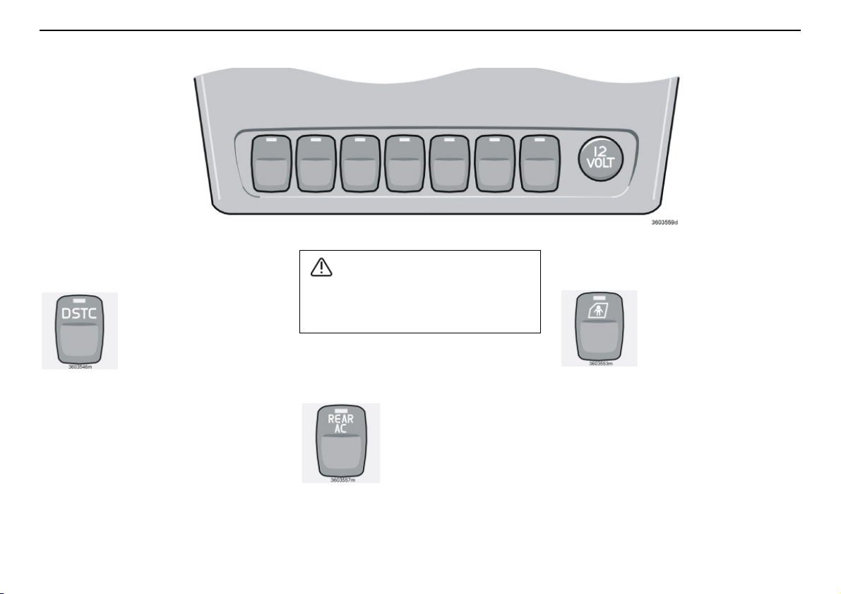
Switches in the centre console
WARNING!
Instruments and controls
NOTE! The order of the buttons may vary.
DSTC system
This button is used to
reduce or reactivate the
functions of the DSTC
system. When the LED in
the button is lit, the DSTC
system is activated
(assuming there is no fault).
NOTE! Hold the button depressed for at
least half a second to reduce the function of
the DSTC system. The LED in the button
goes out and the text "DSTC SPIN
CONTROL OFF" is shown on the display.
Deactivate the system if you must use a
wheel of a different size than the other
wheels.
The DSTC system is reactivated when the
engine is restarted.
Keep in mind that the driving characteristics of the car change if you deactivate
the DSTC system.
Air conditioning in the rear of the
passenger compartment
(option)
Press the button to activate
the air conditioning in the
rear of the passenger
compartment. Rear air
conditioning is deactivated
when the ignition is
completely switched off.
Child safety locks in the rear
doors (option)
Use thisbutton to activateor
deactivate the electric child
safety locks in the rear
doors. The ignition key must
be in position I or II. When
the child safety locks are
activated, the LED in the button lights. A
message is shown on the display when the
child safety locks are activated or deactivated.
49
Page 51
Instruments and controls
Switches in the centre console
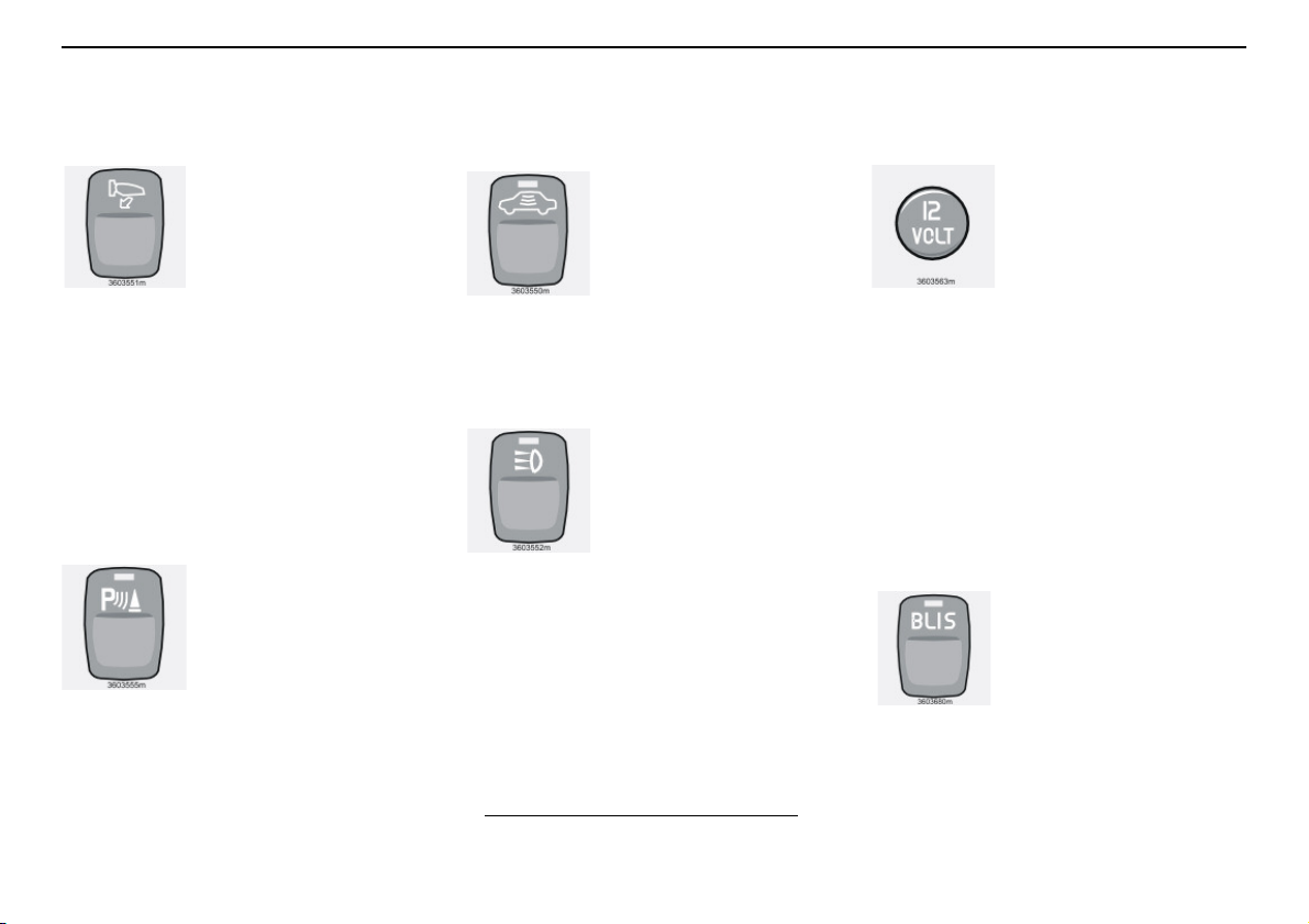
Retractable door mirrors
(option)
This button is used to fold in
the door mirrors if they are
folded out or to fold them
out if they are folded in.
Do as followsif a door mirror
has been accidentallyfolded
in or out:
– Manually adjust the appropriate door
mirror to its normal position.
– Turn the ignition key to position II.
– Fold the door mirror inward and then
outward using the button. The door
mirrors have now returned to their original
fixed positions.
Parking assistance (option)
The system is always
activated when the car is
started. Press the button to
deactivate/reactivate the
parking assistance system.
See also page 125.
Deactivation of the deadlocks
1
and detectors
Use this button when you
wish to switch off the
deadlock function (doors
cannot be opened from the
inside when locked). This
button can also be used
when deactivating the alarm system
movement and tilt detectors. The LED lights
when these systems are deactivated.
2
Auxiliary lamps (accessory)
Use this button to switch the
auxiliary lamps on with main
beam or to switch them off.
The LED in the button is lit
when the function is
activated.
Electric socket, (standard)/
Cigarette lighter (option)
The electric socket can be
used for various 12 V accessories, e.g. mobile phone or
a cooler box.
The ignition key must be at
least in position I so that the
socket can supply power.
The cigarette lighter is activated by pushing
in the button. Once the lighter has been
heated, the button pops out again. Pull out
the lighter to use it. For safety reasons,
always keep the cover in place when the
socket is not in use. Maximum current tap
10 A.
BLIS – Blind Spot Information
System (option)
Press the button to deactivate
or reactivate the function. See
page 143 for further information.
50
1. Certain markets
2. Option
Page 52
Switches in the centre console
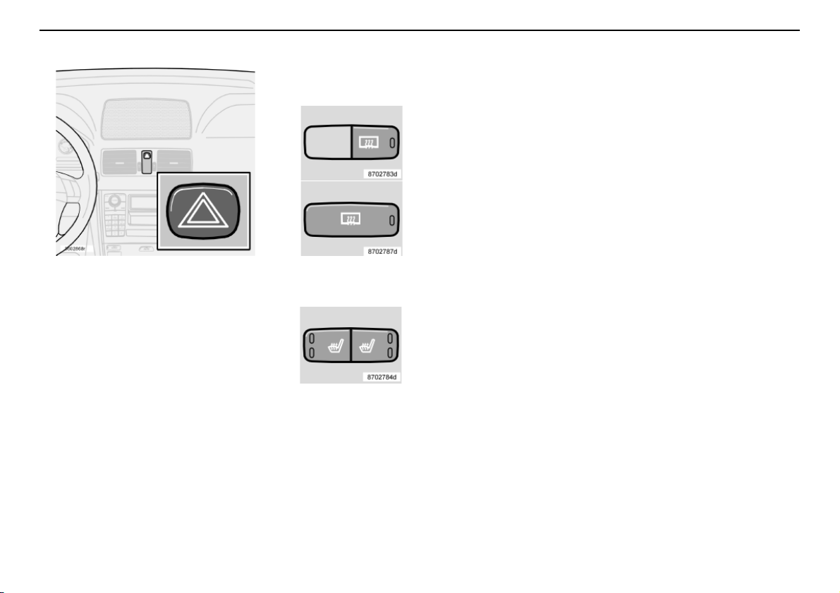
Hazard warning flashers
Use the hazard warning flashers (all direction
indicators flash) when the car is stopped
where it could be a traffic hazard or
obstruction. Press the button to activate the
function.
NOTE! Regulations regarding the use of
hazard warning flashers vary from country to
country.
Instruments and controls
Rear window and door mirror
defrosters
Use the defroster to
remove ice and misting
from the rear window
and door mirrors. Press
the switch to start
defrosting the rear
window and door
mirrors. The LED in the
switch comes on.
Defrosting is automati-
cally disconnected after about 12 minutes.
Heated front seats
See page 71 or 75 for
further information.
51
Page 53
Instruments and controls
Lighting panel
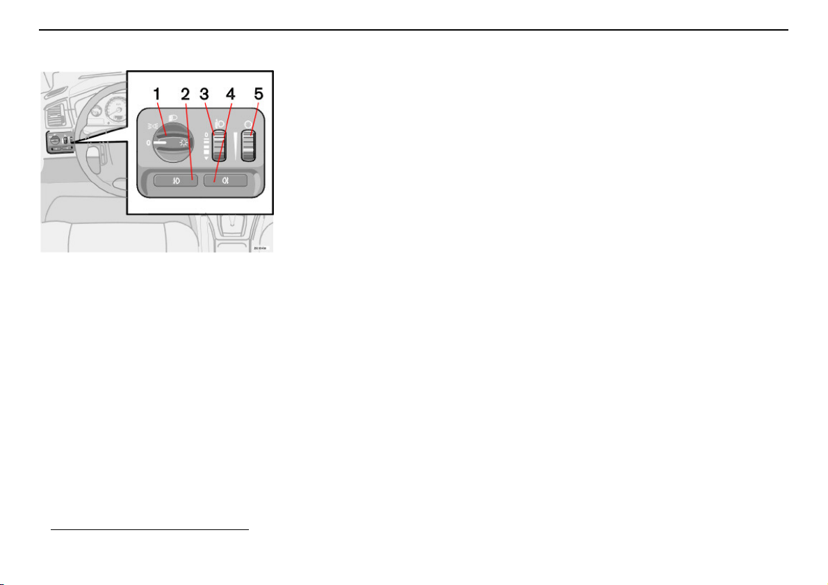
Headlamp levelling
The load in the car changes the vertical
alignment of the headlamp beam, which
could dazzle oncoming motorists. Avoid this
by adjusting the height of the beam.
– Turn the ignition key to position II.
– Turn the headlamp control (1) to one of
the end positions.
– Roll the control up or down (3) to raise or
lower beam alignment.
Cars with Bi-Xenon headlamps
automatic headlamp levelling, so there is no
control (3).
1. Option.
52
1
have
Position/parking lamps
The position lamps/parking lamps can be
switched on irrespective of ignition key
position.
– Turn the headlamp control (1) to the
centre position.
In ignition key position II the position lamps/
parking lamps are always on. The number
plate lightingis switched on at the same tome
as the position lamps/parking lamps.
Headlamps
Automatic dipped beam
Dipped beam comes on automatically when
the ignition key is turned to position II, except
when the headlamp control (1) is in the
centre position. If necessary the automatic
dipped beam can be deactivated by an
authorised Volvo workshop.
Manual dipped beam (certain countries)
– Turn the ignition key to position II.
– Turn the headlamp control (1) clockwise
to the end position.
Main beam
– Turn the ignition key to position II.
– Turn the headlamp control (1) clockwise
to the end position.
– Move the left-hand stalk switch towards
the steering wheel to the end position
and release it, see page 53.
Fog lamp
NOTE! Regulations for use of fog lamps vary
from country to country.
Front fog lamps (option)
The front fog lamps can be switched on along
with the headlamps or the position lamps/
parking lamps.
– Press the button (2).
The LED in the button (2) lights when the
front fog lamps are switched on.
Rear fog lamp
The rear fog lamp can only be switched on
with the headlamps or the front fog lamps.
– Press the button (4).
The rear fog lamp indicator symbol in the
combined instrument panel and the LED in
the button (4) come on when the rear fog
lamp is switched on.
Instrument lighting
The instrument lighting is switched on when
the ignition key is in position II and the
headlamp control (1) is in one of the end
positions. The lighting is automatically
dimmed during the day and can becontrolled
manually at night.
– Roll the control up or down (5) for
brighter or dimmer lighting.
Page 54
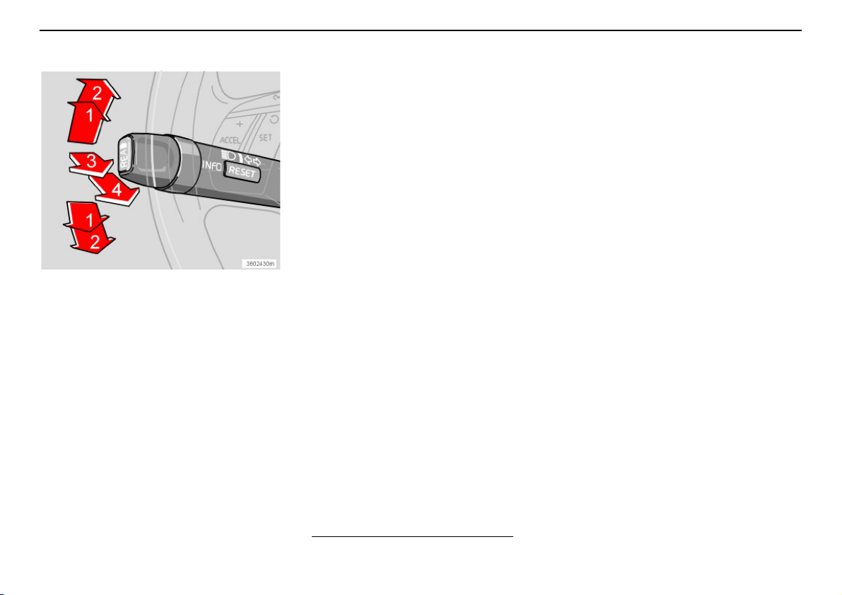
Left-hand stalk switch
Instruments and controls
Stalk switch positions
1. Short flash sequence, direction
indicators
2. Continuous flash sequence, direction
indicators
3. Main beam flash
4. Switching, main and dipped beam, and
home safe lighting
Direction indicators
Continuous flash sequence
– Move the stalk switch up or down to end
position (2).
The stalk switch remains in its end position
and is moved back manually, or automatically
by steering wheel movement.
Short flash sequence
– Move the stalk switch up or down to
position (1) and release.
When the stalk switch is released it returns to
its start position and the direction indicators
are switched off.
Switching, main and dipped
beam
The ignition key must be in position II for
main beam to be switched on.
– Turn the headlamp control clockwise to
the end position, see page 52.
– Move the stalk switch towards the
steering wheel to the end position (4) and
release.
Main beam flash
– Move the stalk switch gently towards the
steering wheel to position (3).
Main beam comes on until the stalk switch is
released.
Home safe lighting
Some of the exterior lighting can be kept
switched on and works as home safe lighting
after the car has been locked. The time delay
is 30 seconds
90 seconds by an authorised Volvo
workshop.
1. Factory settings.
1
, but can be changed to 60 or
– Remove the key from the ignition.
– Move the stalk switch towards the
steering wheel to the end position (4) and
release.
– Get out of the car and lock the door.
53
Page 55
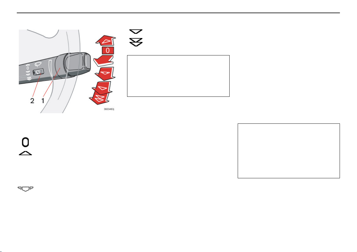
Instruments and controls
IMPORTANT!
IMPORTANT!
Right-hand stalk switch
Wiper/washer function – windscreen.
Windscreen wipers
Windscreen wipers off.
If the lever is in the 0 position and
you move it upwards, the wipers will
sweep one stroke at a time for as long as you
hold the lever up.
Intermittent wiping
You can adjust and set a suitable
speed for intermittent wiping.
Rotate the ring (1) clockwise to increase
wiper stroke frequency. Rotate the ring
anticlockwise to decrease wiper stroke
frequency.
54
Wipers operate at "normal" speed.
Wipers operate at "high" speed.
Use plenty of washer fluid when the
wipers are cleaning the windscreen. The
windscreen must be wet when the
windscreen wipers are operating.
Rain sensor (option)
The rain sensor automatically activates the
windscreen wipers based on how much
water it detects on the windscreen. The
sensitivity of the rain sensor can be adjusted
using the ring (1).
– Turn the ring clockwise to increase sensi-
tivity or anticlockwise to decrease sensitivity. (There is an extra swipe when the
ring is turned clockwise).
On/Off
When activating the rain sensor, the ignition
key must be in position I or II and the
windscreen wiper stalk switch must be in
position 0.
To activate the rain sensor:
– press the button (2). An LED in the
button comes on to indicate that the rain
sensor is active.
To turn the rain sensor off, either:
– press the button (2) or
– press the stalk switch downward to
another wiper programme. If the stalk
switch is raised, the rain sensor will
remain active, the wipers make an extra
sweep and then return to rain sensor
mode when the stalk switch is released
back to position 0.
The rain sensor is automatically deactivated
when the key is removed from the ignition
switch or five minutes after the ignition is
switched off.
In an automatic car wash:
Turn off the rain sensor by pressing the
button (2) while the ignition key is in
position I or II. Otherwise, the
windscreen wipers may start and be
damaged.
Page 56
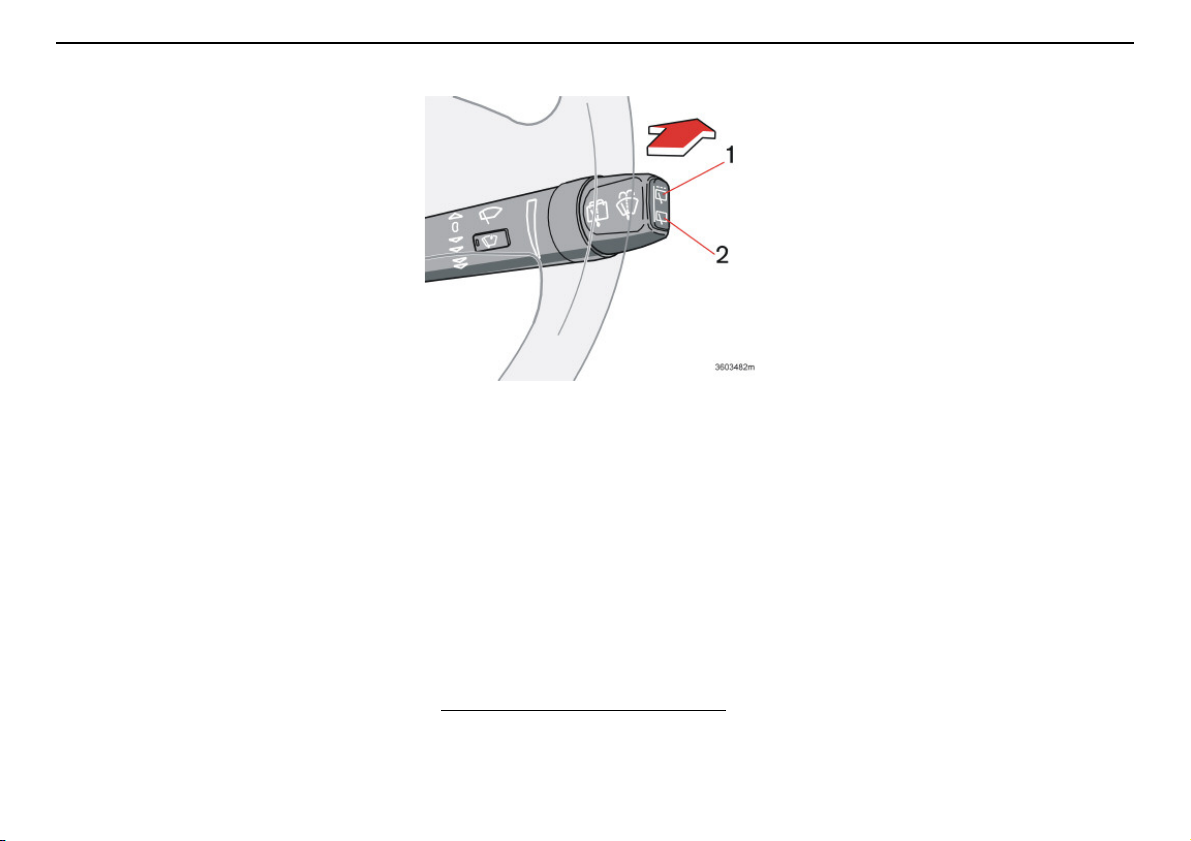
Right-hand stalk switch
Windscreen washer
Pull the lever towards the steering wheel to
activate the windscreen washer.
Headlamp washer
(option on certain markets)
High-pressure wash of the headlamps
consumes a great deal of washer fluid. To
save fluid, the headlamps are only washed
every fifth time (within a ten minute period). If
ten minutes have elapsed since the last
windscreen washing, the headlamps receive
a high-pressure wash the next time the
windscreen is washed.
Reduced washing
If only approx. one litre of washer fluid
remains in the reservoir, the supply to the
headlamps and the rear window is cut off in
order to prioritise cleaning of the windscreen.
Instruments and controls
Wiper/washer function – rear window.
Rear window washer and wiper
Move the lever forward to start the rear
window washer.
1. Rear window wiper – intermittent wiping
2. Rear window wiper – normal speed
Wiper – reversing
If you engage reverse gear when the
windscreen wipers are already activated, the
rear window wipers will go into intermittent
wiping mode1. If the rear window wiper is
already engaged at normal speed, there is no
change to the selected function.
1. This function (intermittent wiping
when reversing) can be deactivated.
Contact an authorised Volvo
workshop.
55
Page 57
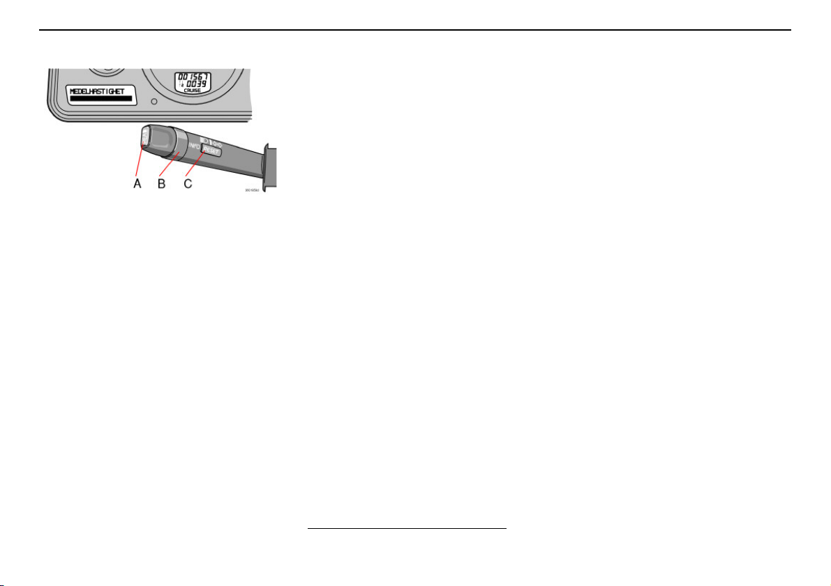
Instruments and controls
Trip computer
Controls
To access the trip computer information, you
must turn the ring (B) in steps, either forward
or backward. By turning again, you return to
the starting point.
NOTE! If a warning message interrupts while
you are using the trip computer, you must first
acknowledge the message by pressing the
READ button (A) to return to the trip
computer.
Functions
The trip computer displays the following
information:
• AVERAGE SPEED
56
• SPEED IN MILES PER HOUR
• CURRENT FUEL CONSUMPTION
• AVERAGE FUEL CONSUMPTION
• RANGE TO EMPTY FUEL TANK
Average speed
The average speed since the last reset
(RESET). When the ignition is switched off,
the average speed is stored and used as the
basis of the new value when you continue
driving. This can be reset with the RESET
button (C) on the lever.
Speed in miles per hour
Current speed is displayed in mph.
Current fuel consumption
Continuous information on current fuel
consumption, calculated each second. The
figure in the display is updated every couple
of seconds. When the car is stationary, "----"
is shown on the display.
NOTE! There may be a slight error in the
reading if a fuel-driven heater is used.
Average fuel consumption
The average fuel consumption since the last
reset (RESET). The average fuel
consumption is stored when the ignition is
switched off and remains until reset with the
RESET button (C) on the lever.
1. Certain countries
1
1
NOTE! There may be a slight error in the
reading if a fuel-driven heater is used.
Range to empty fuel tank
The range to empty is calculated based on
the average fuel consumption over the last
30 km. When the range to empty is shorter
than 20 km then "----" is shown on the
display.
NOTE! There may be a slight error in the
reading if fuel consumption is changed dueto
a change in driving style or if a fuel-driven
heater is used for example.
Page 58
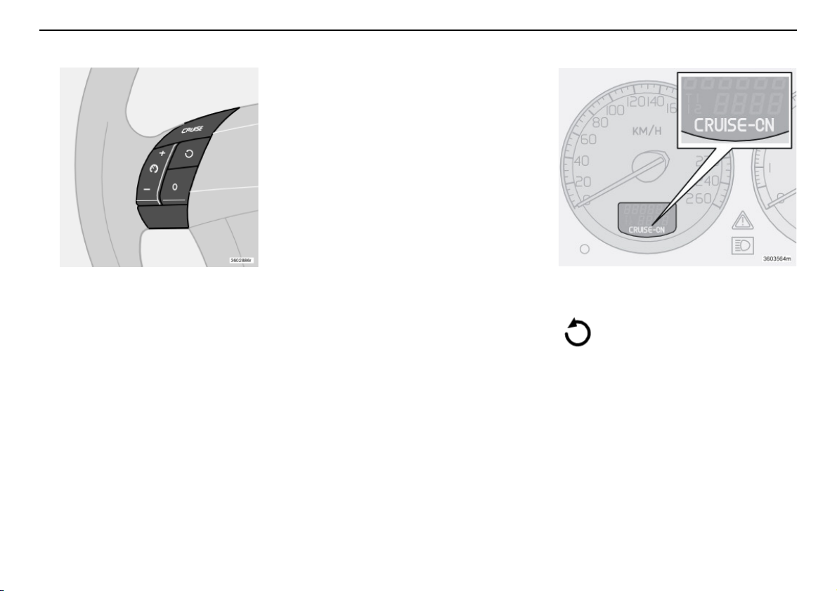
Cruise control
Activating
The controls for cruise control are to the left
of the steering wheel.
Setting the desired speed:
– Press the CRUISE button. CRUISE is
shown on the combined instrument panel.
– Touch + or – to lock the vehicle speed.
CRUISE ON appears on the combined
instrument panel.
Cruise control cannot be engaged at speeds
below 30 km/h or above 200 km/h.
Increasing or decreasing speed
Increase or decrease the speed by pressing
and holding + or –. The speed of the car
when the button is released is set as the new
speed.
A brief press (less than half a second)
on + or – changes the speed by one km/h.
NOTE! A temporary increase in speed (less
than one minute) using the accelerator, such
as whileovertaking, does not affect the cruise
control setting. When you release the accelerator, the car will return to the programmed
speed.
Temporary disengagement
Press 0 to disengage the cruise control
temporarily. CRUISE will be shown on the
combined instrument panel. The speed set
earlier is stored in the memory.
The cruise control is also temporarily disengaged when:
• the brake pedal or clutch pedal is
depressed
• speed falls below 30 km/h when
travelling uphill
• the gear selector is moved to position N
• wheel spin or wheel lock-up occurs
• a temporary increase in speed lasts
longer than one minute.
Instruments and controls
Return to the set speed
Press this button to resume the
previously set speed. CRUISE-ON
appears on the combined
instrument panel.
Disengaging
Press CRUISE to disengage the cruise
control. CRUISE-ON goes out on the
combined instrument panel.
57
Page 59
Instruments and controls
2
1
1
2
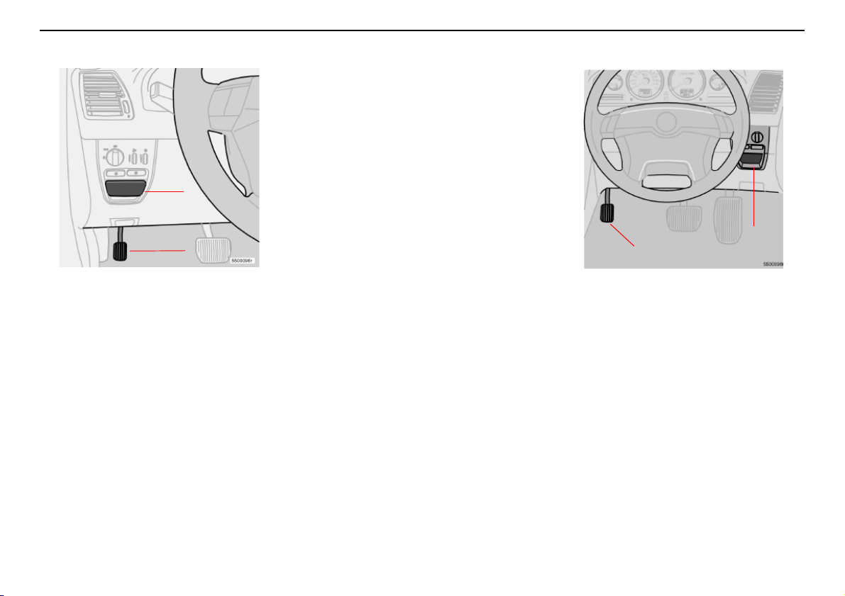
Parking brake, bonnet, electric socket, etc.
Activate the parking brake:
– Press the foot brake down firmly.
– Depress the parking brake to the end
position (1).
– Release the foot brake and make sure
that the car is stationary.
– Move the gear selector into position:
1 for manual gearbox
P for automatic transmission.
Parking on a hill
• If the car is parked uphill, turn the wheels
away from the kerb.
Parking brake, LHD car.
Parking brake
The parking brake is located to the leftat floor
height and acts on the rear wheels when it is
depressed.
The warning symbol in the combined
instrument panel comes on irrespective of
how hard the parking brake is depressed. So
always depress the parking brake to the end
position.
• If the car is parked downhill, turn the
wheels toward the kerb.
Release the parking brake:
– Press the foot brake down firmly.
– Pull out the handle (2).
Parking brake, RHD car.
58
Page 60
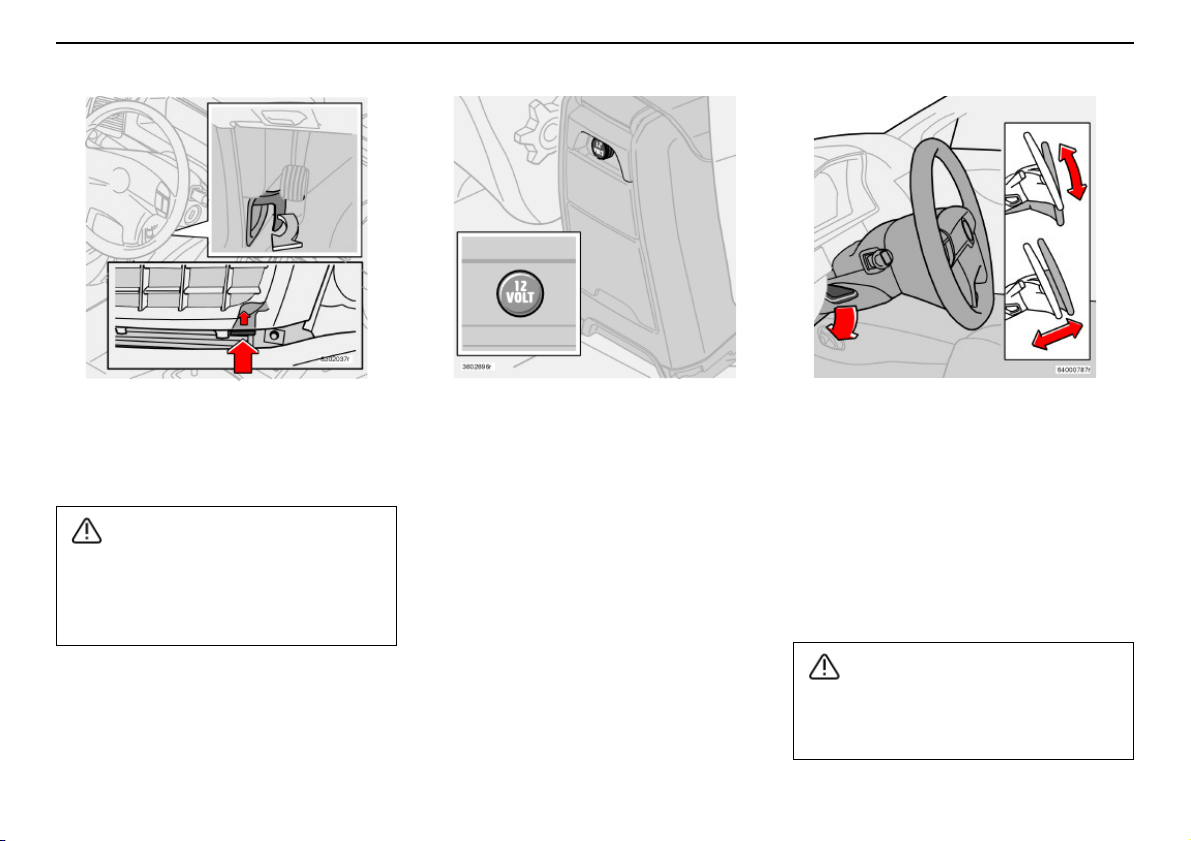
Parking brake, bonnet, electric socket, etc.
WARNING!
WARNING!
Instruments and controls
Opening the bonnet
Pull the handle towards you to release the
bonnet lock mechanism.
Close the bonnet by placing your hand on
its top and pressing down. Do not close it
by holding the grille. Engine components
on the inside could injure your fingers.
Electrical socket for rear seat
passengers (option)
The electric socket can be used for various
12 V accessories, such as mobile phones or
CD players. The maximum current is 10 A.
The ignition key must be at least in position I
so that the socket can supply power.
Steering wheel adjustment
The steering wheel can be adjusted both
vertically and front-rear. Press down the
control on the left-hand side of the steering
column. Then adjust the steeringwheel to the
position that suits you best. Press the control
back into place to lock the steering wheel. If
this is difficult, press the steering wheel
slightly while pressing the control back.
Adjust the steering wheel before driving,
never while driving. Ensure that the
steering wheel is locked.
59
Page 61
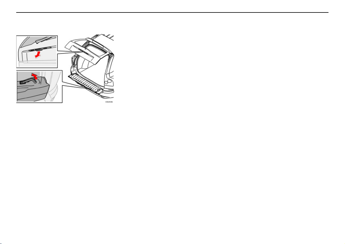
Instruments and controls
Parking brake, bonnet, electric socket, etc.
Opening the tailgate
Open the tailgate by pulling the handle
indicated in the illustration. Fold down the
rear flap by lifting the handle up.
60
Page 62
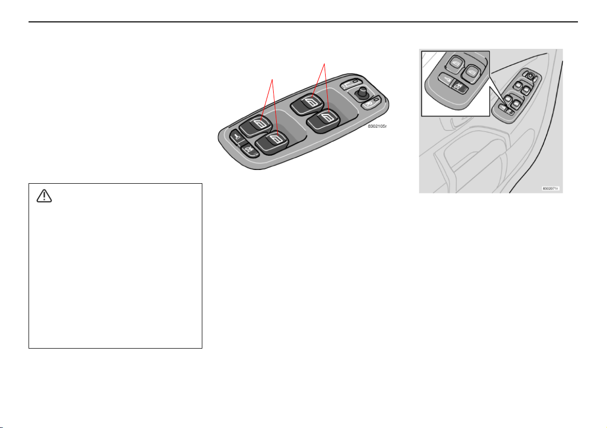
Power windows
WARNING!
B
A
The power windows are operated using the
controls in the door armrests. The ignition key
must be turned to position I or II for the
power windows to work. Once you finish
driving and remove the ignition key, the
windows can still be opened or closed as
long as neither of the front doors has been
opened.
Open a window by depressing the front of
the control,and close itby pulling up the front
of the control.
Instruments and controls
If there are children in the car:
• Remember to switch off the supply to
the power windows by removing the
ignition key if the driver leaves the car.
• Make sure that children’s and other
passengers’ hands are clear when
closing the windows.
If the rear door windows are operated
from the driver’s door:
• Check that none of the rear seat
passengers are in danger of getting their
hands caught when closing the windows.
Power windows in the front
doors
Windows can be opened or closed from the
front seat two ways.
– Press the control (A) slightly down or pull
it slightly up. The power windows go up
or down as long as the switch is actuated.
– Press the control (A) all the way down or
pull it all the way up, and then release.
The windows then open or close automatically. Movement is stopped if the window
is blocked in any way.
NOTE! The function auto up for the
passenger side is only available in certain
markets.
Controls (B) to operate windows in the rear
doors.
Blocking power windows in the
rear doors
The power windows in the rear seat can be
blocked with the switch on the driver’s door
control panel. Always remember to switch off
current to the power windows (i.e. remove
the ignition key) if you leave children in the car
unattended.
LED in the switch is unlit
The rear door windows can be operated both
with the control on each rear door and with
the controls on the driver’s door.
61
Page 63
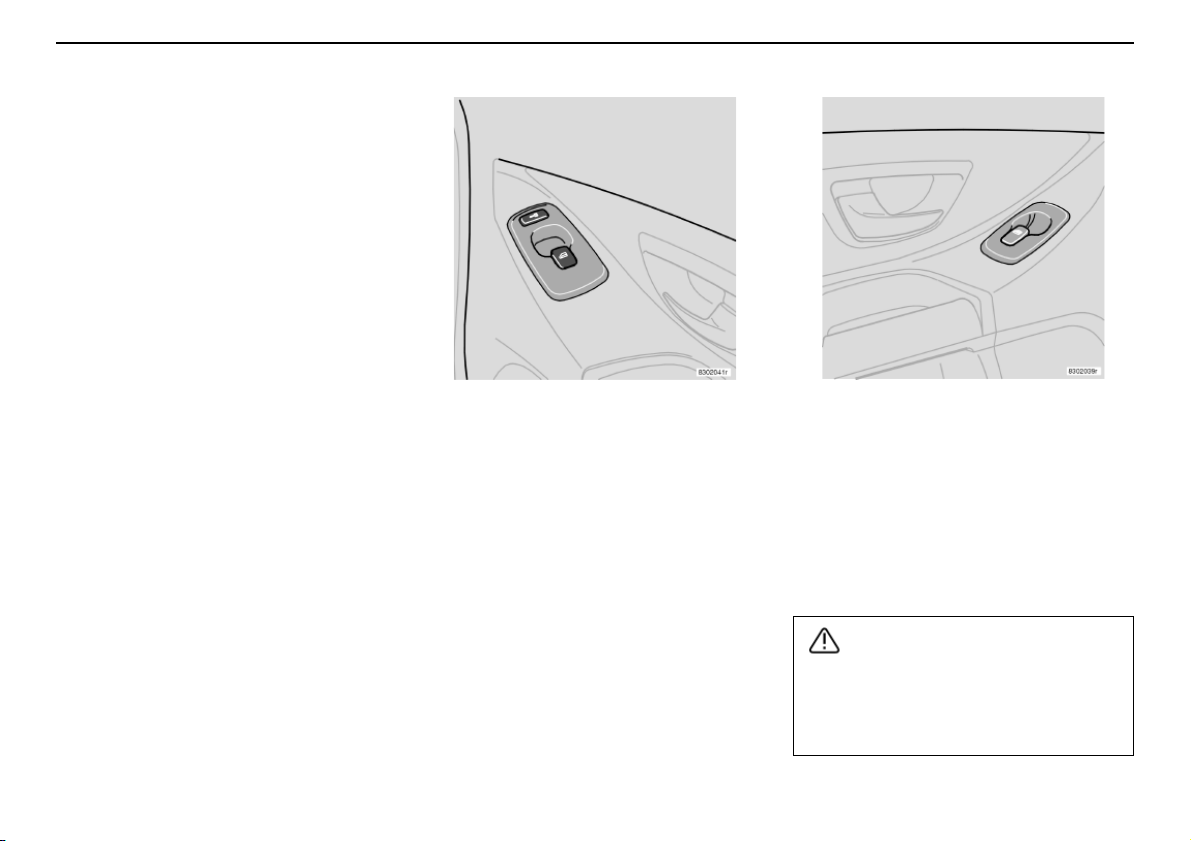
Instruments and controls
WARNING!
Power windows
LED in the switch is lit
The rear door windows can only be operated
from the driver’s door.
62
Power window in the front
passenger seat
The control for the power window at the front
passenger seat operates that window only.
Power windows in the rear doors
The rear door windows can be operated with
the controls on the doors and the switch on
the driver’s door. If the LED in the switch for
blocking power windows in the rear doors
(located in the driver’s door control panel) is
lit, the rear door windows can only be
operated from the driver’s door.
If rear door windows are being operated
from the driver’s door, check that no rear
seat passenger are in danger of getting
pinched when the windows close.
Page 64
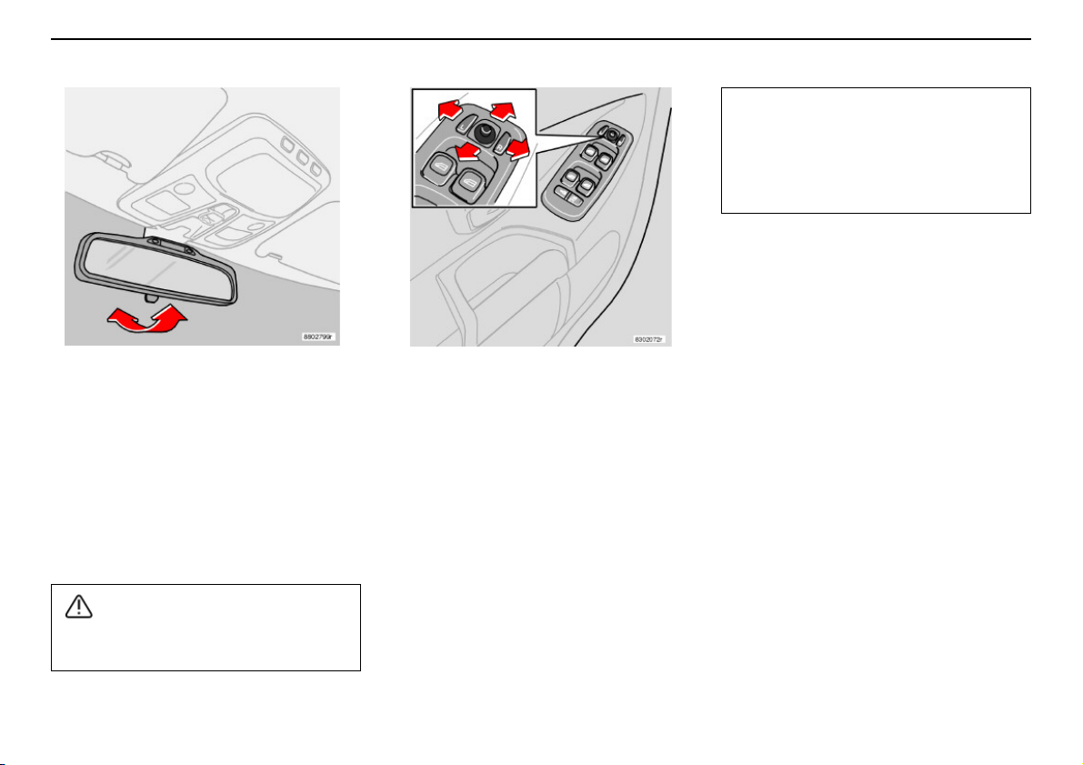
Rearview mirror, door mirrors and side windows
WARNING!
A
B
IMPORTANT!
Interior rearview mirror
A. Normal position.
B. Dimming position. Use this if headlamps
from the car behind are irritating you.
Certain models have an auto-dim function
(option). Dimming occurs automatically
based on comparative light relationships. An
authorised Volvo workshop can adjust the
sensitivity.
Adjust the mirrors before you begin
driving!
Door mirrors
The controls for adjusting the two door
mirrors are at the front of the driver’s door
armrest.
– Press the L or R button (L = left door
mirror, R = right door mirror). The LED in
the button lights.
– Adjust the position with the adjustment
control in the centre. Press the button
again. The LED should no longer be lit.
Instruments and controls
Use the defroster (see page 51) to
remove ice from the mirrors, not an ice
scraper. The scraper could scratch the
mirror glass.
Door mirrors with memory
function (option)
If the car has door mirrors with memory
function, they work together with the memory
setting of the seat, see page 81.
Memory function in the remote control
(option)
When you unlock the car with one of the
remote controls and change thesetting of the
door mirrors, these new settings are saved in
the remote control. The next time you unlock
the car with the same remote control and
open the driver’s door within five minutes, the
mirrors will assume their stored positions.
Laminated side windows
(option)
The laminated windows in the front and rear
doors improve sound insulation in the
passenger compartment and provide better
protection against unauthorised entry.
63
Page 65
Instruments and controls
IMPORTANT!
Rearview mirror, door mirrors and side windows
Water and dirt-repellent coating
on the front windows and/or
door mirrors (option)
The front windows and/or door mirrors are
treated with a coating that ensures that the
view through the windows or in the mirrors is
good even if it is raining. For information on
glass care, see page 165.
Side windows and mirrors
treated with the water and
dirt-repellent coating are
marked with a small symbol.
Rearview and door mirrors
In certain weather conditions, the function of
the dirt-repellent coating is improved if the
door mirror defrosters are used, see page 51.
Defrost the door mirrors:
• if they are covered with ice or snow
• in heavy rain and dirty road conditions
• if they are misted.
Do not use a metal ice scraper to remove
ice from the windows. The water and dirtrepellent coating could be damaged.
Use the defroster to remove ice from the
mirrors!
64
Page 66
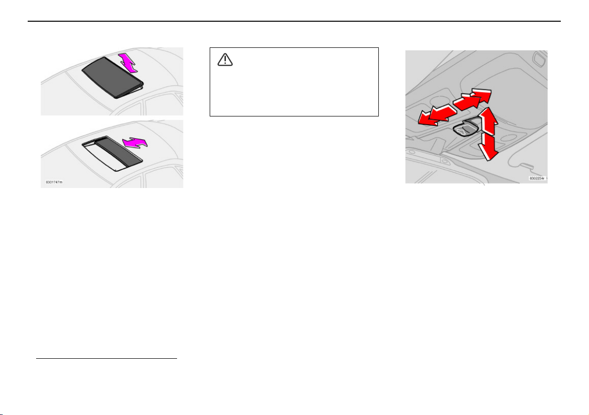
Power sunroof (option)
A
B
WARNING!
1
2
3
4
5
6
Instruments and controls
If there are children in the car: remember
to switch off the supply to the power
sunroof (remove the ignition key) if the
driver leaves the car.
Open positions
Sunroof controls are located in the
headlining. The sunroof can be opened in two
different ways:
A. Raise/lower trailing edge – ventilation
position
B. Rearwards/forwards – opening
position/comfort position
key must be in position I or II.
1. In comfort position, the sunroof is not
completely open in order to reduce
the level of wind noise.
1
. The ignition
1. Automatic closing
2. Closing, manual
3. Opening, manual
4. Opening, automatic
5. Opening, ventilation position
6. Closing, ventilation position
Ventilation position
Open: Push the trailing edge of the
control (5) upward.
Close: Pull the trailing edge of the control (6)
downward.
Switch from ventilation position to comfort
position: pull the control rearwards to its end
position (4) and release.
65
Page 67
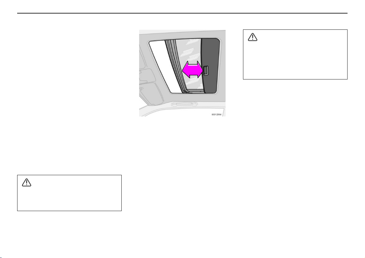
Instruments and controls
WARNING!
WARNING!
Power sunroof (option)
Automatic operation
Move the control over the resistance point
position (3) to the rearmost end position (4)
or over theresistance point position (2) to the
front end position (1) and release. The
sunroof will open to the comfort position or
will close completely.
In order to open from comfort position to
maximum opening: Pull the control to the rear
once more to the end position (4) and
release.
Manual operation
Open: Pull the control rearwards to the
resistance point position (3). The sunroof will
move towards maximum opening position as
long as the control is held in this position.
Close: Press the control forward to the
resistance point (2). The sunroof moves
towards closing position as long as the
control is held in this position.
If you have children in the car, make sure
that their hands areclear when closing the
sunroof.
The sunroof’s pinch protection function
only operates during automatic closing,
not during manual closing.
Make sure children’s hands are clear
when closing the sunroof.
Sunscreen
The sunrooffeatures a manual, sliding interior
sunscreen. The sunscreen slides back
automatically when the sunroof is opened.
Grip the handle and slide the screen
forwards to close the screen.
Pinch protection
The sunroof’s pinch protection function is
activated if the hatch is blocked by an object.
If blocked, the sunroof will stop and automatically open to the previous position.
66
Page 68

Climate control
General information on climate control 68
Manual climate control, A/C 70
Electronic Climate Control, ECC 73
Parking heater (option) 76
67
Page 69

Climate control
General information on climate control
Misting windows
Reduce the problem of windows misting up
on the inside by cleaning the windows. Use a
regular window cleaner.
Particle filter
Make sure the particle filter is replaced
regularly. Consult an authorised Volvo
workshop.
Ice and snow
Remove ice and snow from the climate
control air intake (the grille between the
bonnet and the windscreen).
Fault tracing
An authorised Volvo workshop has the instruments and tools required for any fault tracing
or repair of your climate control system.
Entrust checks and repairs only to trained
personnel.
Refrigerant
The air conditioning system contains R134a
refrigerant. This refrigerant contains no
chlorine, which means that it is harmless to
the ozone layer. The system must only be
charged with R134a refrigerant. Have an
authorised Volvo workshop carry out this
work.
Ventilation fan function
When the engine is off (and if the ignition key
is in position I or II), the ventilation fan is
automatically switched off. This is to prevent
the battery from becoming discharged.
To activate the ventilation fan, turn the fan
control and set the desired speed.
Cars with ECC
Actual temperature
The temperature you select corresponds to
the physical experience with reference to air
speed, humidity, exposure to sun, etc. which
affect the interior and exterior of the car.
Sensors
The sun sensor is on the upper portion of the
dashboard. Remember not to cover it. Do not
cover the passenger compartment temperature sensor on the climate control panel.
Side windows and sunroof
To ensure that the air conditioning works
satisfactorily, close all side windows and the
sunroof (if fitted).
Acceleration
The air conditioning system switches off
temporarily at full acceleration. You may feel
a temporary rise in temperature.
Condensation
In warm weather, condensation from the air
conditioning system may drip under the car.
This is normal.
Fuel economy
With ECC, the air conditioning system is
controlled automatically and is used just
enough to cool the passenger compartment
and to adequately dehumidify the incoming
air. This provides better fuel economy
compared to conventionalsystems where the
air conditioning cools the air to just above
freezing point.
68
Page 70
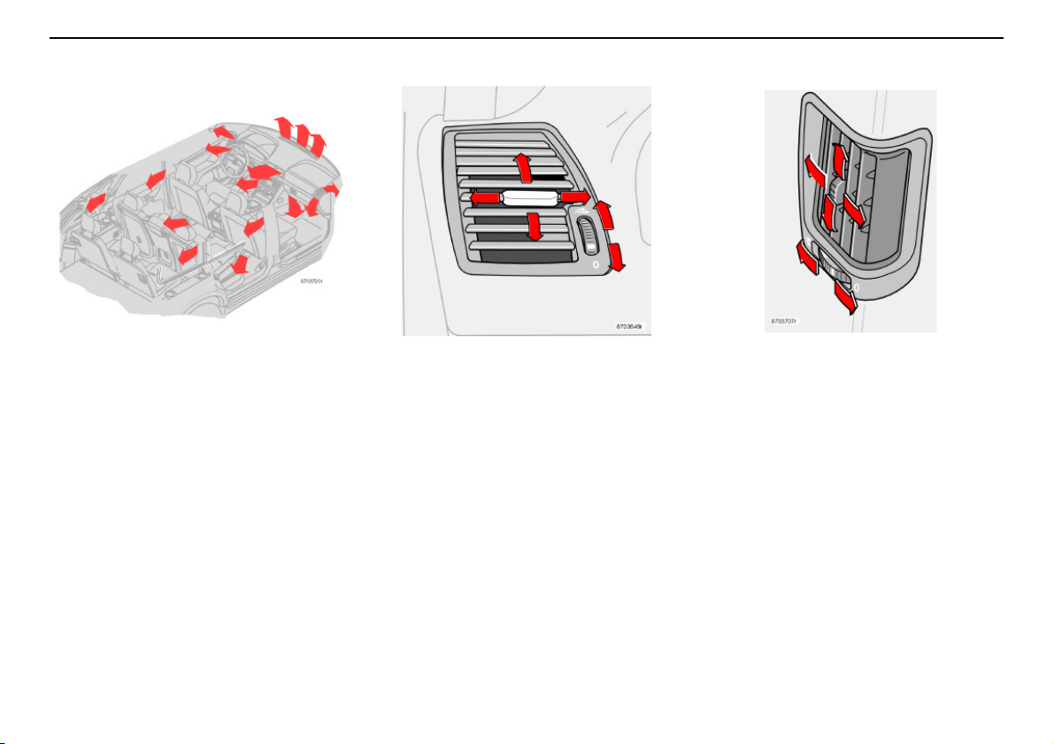
General information on climate control
A
B
C
D
A
B
C
D
Climate control
Air distribution
Incoming air is distributed through several
different vents located throughout the car.
Air vents in the dashboard
A. Open
B. Closed
C. Lateral airflow
D. Vertical airflow
– Aim the outer vents towards the side
windows to remove misting.
– In cold climates: close the centre vents
for the most comfortable climate and best
demisting.
Air vents in the door pillars
A. Open
B. Closed
C. Lateral airflow
D. Vertical airflow
– Aim the vents towards the windows to
remove misting from the rear side
windows.
– Aim the vents inwards into the car for a
comfortable climate in the rear seat.
Bear in mind that small children can be
sensitive to airflow and draughts.
69
Page 71
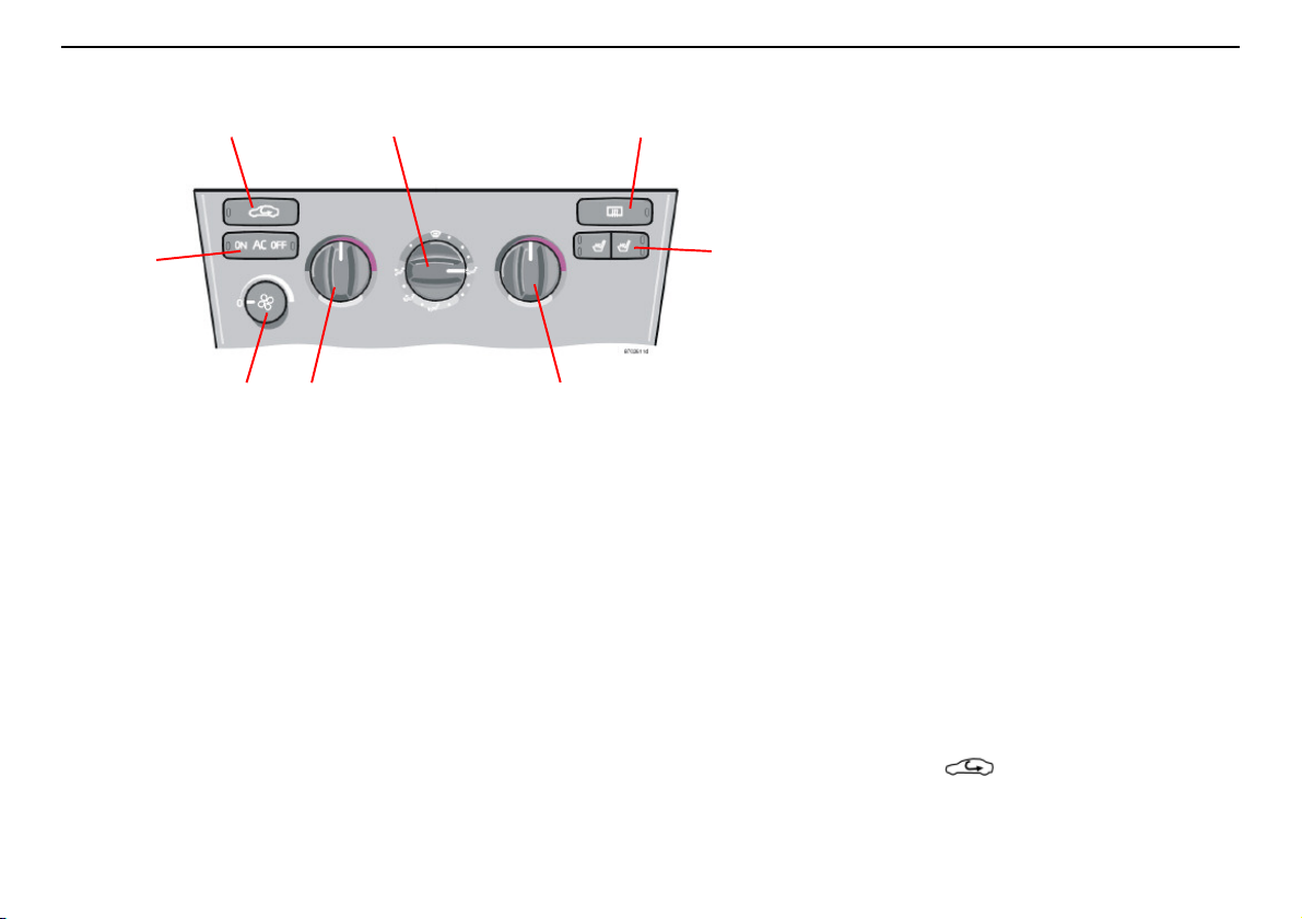
Climate control
1
2 3 4
7 6
5
8
Manual climate control, A/C
1. A/C – ON/OFF
2. Recirculation
3. Air distribution
4. Rear window and door mirror defroster
5. Heated front seats
6. Heating/Cooling right-hand side
7. Heating/Cooling, left-hand side
8. Fan
70
You must turn the fan knob (8) from the 0
position to connect the air conditioning.
Use the air conditioning at low temperatures
too (0–15 °C) in order to dehumidify
incoming air.
1. A/C – ON/OFF
The air conditioning is connected to the
cooling and dehumidification function with
the ON LED lights. The air conditioning is
disconnected with the OFF LED lights.
2. Recirculation
Recirculation can be used to shut out bad air,
exhaust, etc. from the passenger
compartment. The air in the passenger
compartment is then recirculated, i.e. no air
from outside the car is taken into the car
when this function is activated. Recirculation
(together with the air conditioning system)
cools the passenger compartment more
quickly in a warm climate.
If you allow the air in the car to recirculate,
there is a risk of icing and misting, especially
in winter. The timer function minimises the
risk of ice, misting and bad air.
Activate the function as follows:
– Press for more than 3 seconds.
The LED flashes for 5 seconds. The air
recirculates in the car for 3 – 12 minutes
depending on the outside temperature.
Page 72
Manual climate control, A/C
Climate control
– The timer function is activated each time
you press .
To switch off the timer function:
– Press again for more than
3 seconds. The LED lights for 5 seconds
to confirm your selection.
3. Air distribution
Use the air distribution control positions
(marked with dots) between the different
symbols to fine-tune air distribution for
maximum comfort.
Defroster
The defroster on the air distribution
control is used to quickly remove misting and
ice from the windscreen and side windows.
Air flows to the windows at high speed.
When the function is selected the following
also takes place to provide maximum
dehumidification of the air in the passenger
compartment:
• the air conditioning (A/C) is automatically
engaged (if the fan is not in position 0)
• recirculation is automatically disengaged.
When the defroster is switched off the
climate control returns to the previous
settings.
4. Rear window and door mirror
defroster
Use this button to quickly remove misting and
ice from the rear window and door mirrors,
see page 51for further information aboutthis
function.
5. Heated front seats
Do as follows for heated front seat(s):
– Press once: High heat – both LEDs in the
switch light up.
– Press twice: Low heat – one LED in the
switch lights up.
– Press yet again: Heating is switched off –
no LEDs in the switch are lit.
An authorised Volvo workshop can adjust the
temperature.
6. and 7. Heating/Cooling – left/
right-hand side
Turn toset how warm or cold the incoming air
should be. For cooler air, the air conditioning
must be connected.
8. Fan
Fan speedcan be increased or decreasedby
turning the knob.
If the knob is setto 0 then the air conditioning
is not engaged.
71
Page 73
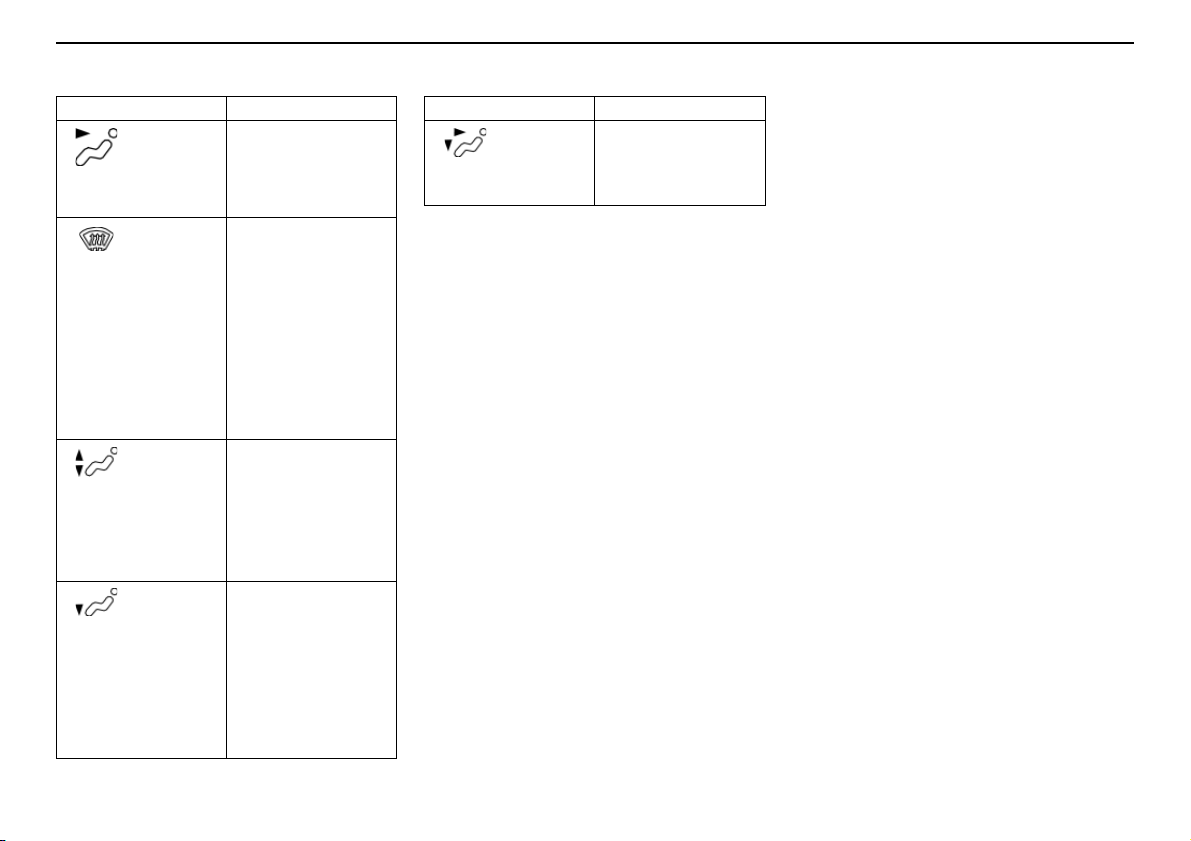
Climate control
Manual climate control, A/C
Air distribution Use
Air through
front and
rear air
vents.
Air to
windows.
Air is not
recirculated in this
position. The air
conditioning is
always connected.
There is a certain
amount of airflow
to the air vents.
Air to both
floor and
windows.
There is a certain
amount of airflow
to the air vents.
Air to floor.
There is a
certain
amount of airflow
to the air vents and
the defroster vents
for the windscreen
and side windows.
When you want
good cooling in a
warm climate.
When you want to
remove ice and
misting. High fan
speed is good for
this.
When you want
comfortable conditions and good
demisting in a cold
climate. Not too
low a fan speed.
When you want to
warm your feet.
Air distribution Use
Air to floor
and air
vents.
In sunny weather
with cool outside
temperatures.
72
Page 74
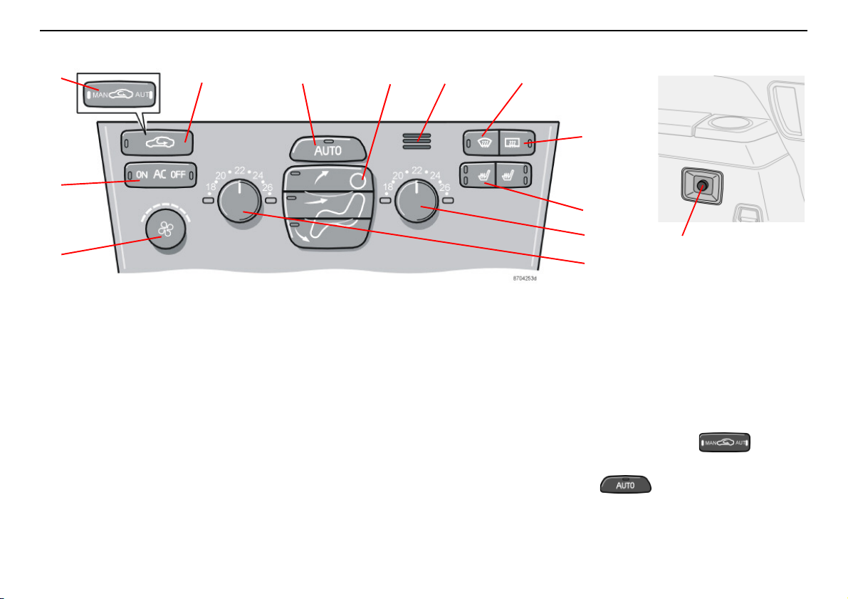
Electronic Climate Control, ECC
3 42 5 6 7
8
9
1
12
11
10
13
Climate control
1. A/C – ON/OFF
2. Recirculation/Multifilter with sensor
3. Recirculation
4. AUTO
5. Air distribution
6. Passenger compartment temperature
sensor
7. Defroster, windscreen and side
windows
8. Rear window and door mirror defroster
9. Heated front seats
10. Temperature, right-hand side
11. Temperature, left-hand side
12. Fan
13. Fan, rear passenger compartment
(option in cars seating seven)
1. A/C – ON/OFF
The air conditioning system is controlled
automatically by the system when the ON
LED is lit. This way, incoming air is cooled
and dehumidified sufficiently. When A/C
OFF is selected and the OFF LED comes on,
the air conditioning system is always disconnected; other functions are still controlled
automatically. The air conditioning system
operates down to approximately 0 °C.
2. Air quality system (option in
certain markets)
Certain cars are equipped with a "Multifilter"
and air quality sensor. The Multifilter
separates gases and particles, thus reducing
the volume of odours and pollu tants. The air
quality sensor detects increased levels of
contaminants in the outside air. When the air
quality sensor detects contaminated outside
air, the air intake is closed and the air in the
passenger compartment is recirculated. The
Multifilter also cleans the air recirculating in
the passenger compartment.
When the air quality sensor is active, the
green AUT LED lights in .
Operation
Press to activate the air quality
sensor (normal setting).
73
Page 75
Climate control
Electronic Climate Control, ECC
Or:
Select one of the following three functions by
pressing repeatedly.
• MAN LED lit: Recirculation is now
activated.
• No LED lit: Recirculation is not activated
unless needed to cool in a warm climate.
• AUT LED lit: The air quality sensor is now
activated.
Keep in mind the following:
• Make it a rule to have the air quality
sensor activated at all times.
• Recirculation is limited in cold weather to
avoid misting.
• If misting occurs, you should deactivate
the air quality sensor.
• If misting occurs, you can use the
defroster functions for the windscreen,
side windows and rear window.
• Follow the Volvo Service Programme for
the recommended replacement interval of
the Multifilter. If the car is used in a
severely contaminated environment, it
may be necessary to change the Multifilter more often.
3. Recirculation
Recirculation can be used to shut out bad air,
exhaust, etc. from the passenger
compartment. The air in the passenger
compartment is then recirculated, i.e. no air
from outside the car is taken into the car
when this function is activated.
If you allow the air in the car to recirculate,
there is a risk of icing and misting, especially
in winter.
The timer function (cars with Multifilter and air
quality sensor have no timer function)
minimises the risk for ice, misting and bad air.
Activate the function as follows:
– Press for more than 3 seconds.
The LED flashes for 5 seconds. The air
recirculates in the car for 3 – 12 minutes
depending on the outside temperature.
– The timer function is activated each time
you press .
To switch off the timer function:
– Press again for more than
3 seconds. The LED lights for 5 seconds
to confirm your selection.
4. AUTO
AUTO function automatically regulates
climate control so that the desired temperature is attained. The automatic function
controls heating, air conditioning, air quality
sensor, fan speed, recirculation, and air
distribution. If you select one or more
functions manually, the other functions
continue operating automatically. All manual
settings are switched off when AUTO is
pressed.
5. Air distribution
• When the top button is depressed, air is
directed to the windows.
• When the centre button is depressed, air
is directed to the head and body.
• When the lower button is depressed, air
is directed to the legs and feet.
Press AUTO to return to automatic air distribution.
6. Passenger compartment
temperature sensor
The passenger compartment temperature
sensor monitors the temperature inside the
car.
74
Page 76

Electronic Climate Control, ECC
Climate control
7. Defroster, windscreen and
side windows
Used to quickly remove misting and ice from
the windscreen and side windows. Air flows
to the windows at high speed. The LED in the
defroster button comes on when this function
is engaged.
When the function is selected the following
also takes place to provide maximum
dehumidification of the air in the passenger
compartment:
• the air conditioning (A/C) is automatically
engaged (if the fan knob is in final
anticlockwise position then the air conditioning is not engaged).
• recirculation is automatically disengaged.
When the defroster is switched off the
climate control returns to the previous
settings.
8. Rear window and door mirror
defrosters
Use this button to quickly remove misting and
ice from the rear window and door mirrors,
see page 51for further information about this
function.
9. Heated front seats
Do as follows for heated front seat(s):
• Press once: high heat – both LEDs in the
switch light up.
• Press twice: low heat – one LED in the
switch lights up.
• Press yet again: Heating is switched off –
no LED in the switch is lit.
An authorised Volvo workshop can adjust the
temperature.
10 and 11. Temperature
The two knobs can be used to set the
temperature for the passenger and driver’s
sides of the car. Remember that the car does
not heat up or cool down any more quickly
even if you select a higher or lower temperature than you want in the passenger
compartment.
12. Fan
Fan speedcan be increased or decreasedby
turning the knob. If AUTO is selected, fan
speed is controlled automatically. The previously set fan speed is disconnected.
If the knob for the fan is turned so far to the
left that only the left LED above the knob
lights with an orange glow, the fan and air
conditioning are switched off.
13. Fan, rear passenger
compartment (option in cars
seating seven)
Fan speed can be increased or decreased by
turning the knob. This only applies if A/C is
selected for both front (1) and rear
passenger compartment. The button for rear
passenger compartment is in the centre
console switch panel, see page 49.
75
Page 77
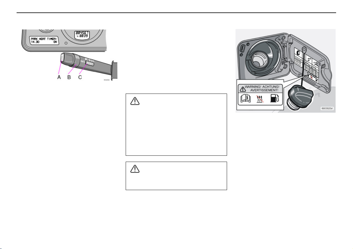
Climate control
WARNING!
WARNING!
Parking heater (option)
General
The electrical system must be "awakened"
before the parking heater can be
programmed.
This is most easily done by:
• pressing the READ button or
• pressing the main beam flash or
• turning on the ignition.
The parking heater can be started immedi-
ately or set with two different start times
using TIMER 1 and TIMER 2. Start time
refers to the time the car should be heated
and ready.
The car’s electronic system calculates when
heating should be started based on the
76
outside temperature. If the outside temperature exceeds 25 °C, the heater does not
switch on. At temperatures of –10 °C and
below, the maximum running time of the
parking heater is 60 minutes.
If the parking heater does not start despite
repeated attempts, a message is shown on
the display. Contact an authorised Volvo
workshop.
• Switch off the fuel-driven heater before
refuelling. Spilled fuel could be ignited by
the exhaust gases.
• Check on the information display that
the heater is off. (When the additional
heater is running, PARK HEAT ON is
shown on the display.)
The car must be outdoors when the petrol
or diesel heater is used.
Warning decal on fuel filler flap.
Messages on the display
Once the settings for TIMER 1, TIMER 2 and
Direct Start are activated, the amber warning
symbol in the combined instrument panel
comes on and explanatory text is shown on
the display.
When you leave the car, you will receive a
message regarding the current settings of
the system.
Parking on a hill
If you park your car on a steep incline, the
front of the car should be facing up the slope
to ensure the supply of fuel to the parking
heater.
Page 78
Parking heater (option)
IMPORTANT!
Climate control
Car clock/timer
For safety reasons, all timer settings will be
cleared if the car clock is reset after timer
settings have been made.
Setting TIMER 1 and 2
For safety reasons, you can only programme
times for the following 24 hours, not several
days in advance.
– Use the ring (B) to toggle to TIMER 1.
– Briefly press the RESET button (C) so
that the hours setting starts to flash.
– Use the ring (B) to set the desired hours.
– Briefly press the RESET button so that
the minutes setting starts to flash.
– Use the ring (B) to set the desired
minutes.
– Briefly press the RESET button to confirm
your setting.
– Press the RESET button to activate the
timer.
After setting TIMER 1, toggle to TIMER 2.
Settings are made the same way as for
TIMER 1.
Deactivating timer-started heating
Do as follows to manually switch off the
heater before the set time has elapsed:
– Press the READ button (A).
– Use the ring (B) to toggle to PARK HEAT
TIMER 1 or 2. The text ON flashes.
– Press the RESET button (C). The text
OFF is displayed with a steady glow and
the heater is switched off.
Direct start
– Use the ring (B) to toggle to DIRECT
START.
– Press the RESET button (C) to access
the alternatives ON or OFF.
Select ON.
The heater will now run for 60 minutes.
Heating of the passenger compartment will
begin as soon as the engine coolant has
reached an adequate temperature.
Deactivating heater after direct start
– Use the ring (B) to toggle to DIRECT
START.
– Press the RESET button (C) to make ON
and OFF selections available.
– Select OFF.
Battery and fuel
If the battery is not sufficiently charged or the
petrol tank is close to empty, the parking
heater will be switched off. If this is the case,
you will receive a message in the display.
Confirm the message using the READ
button (A).
Repeated use of the parking heater in
combination with short trips can lead to
battery discharge and thereby difficulty
starting.
If the heater is used regularly, the car
should be driven for the same amount of
time as the heater was used in order to
ensure that the generator is able to
produce enough energy to compensate
for the amount consumed.
Additional heater (diesel)
(certain countries)
Extra heat from the additional heater may be
required in cold weather to reach the correct
temperature in the passenger compartment.
The additional heater starts automatically
when extra heat is required if the engine is
running. It is switched off automatically when
the correct temperature is reached or when
the engine is switched off.
77
Page 79

Climate control
78
Page 80

Interior
Front seats 80
Interior lighting 83
Storage spaces in the passenger compartment 85
Rear seat 90
Cargo compartment 92
79
Page 81
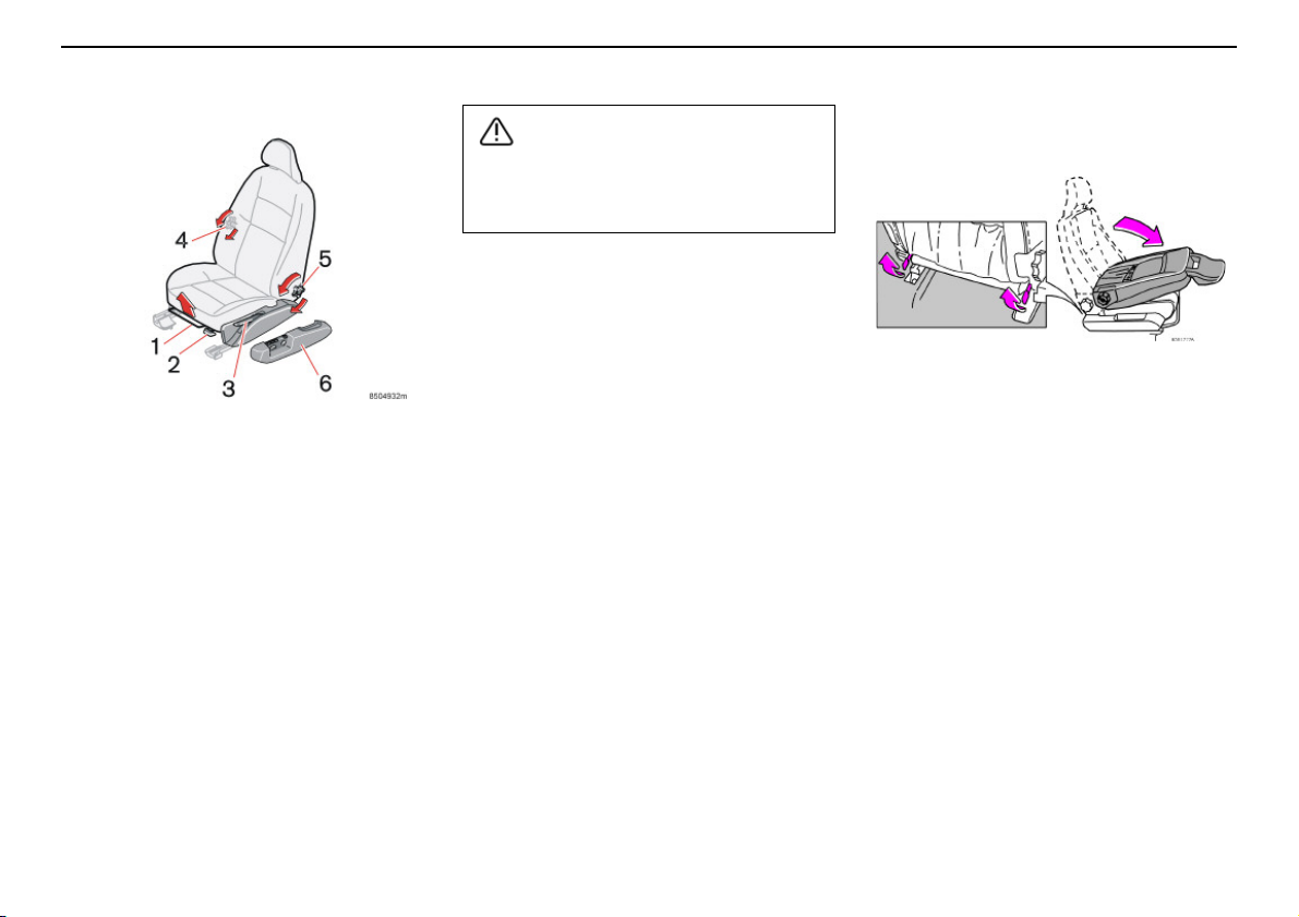
Interior
WARNING!
Front seats
Adjust the position of the driver’s seat
before setting off, never while driving.
Check that the seat is locked in position.
Seating position
The driver’s and passenger seats can be
adjusted to the optimum sitting and driving
positions.
1. Forward/rearward: lift the handle to
adjust the distance to the steering
wheel and pedals. Check that the seat is
locked after changing position
2. Raise/lower front edge of seat cushion:
pump up/down
3. Raise/lower seat: pump up/down
4. Lumbar support: turn the wheel
5. Backrest rake: turn the wheel
6. Power seat control panel.
80
Lowering the front seat backrest
The front passenger seat backrest can be
folded to a horizontal position to make room
for a long load. Fold the backrest as follows:
– Move the seat as far back as possible.
– Adjust the backrest to the upright
position.
– Lift the catches on the rear of the
backrest.
– Fold the backrest forward.
– Slide the seat forward so that the head
restraint is "locked in place" under the
glovebox.
Page 82
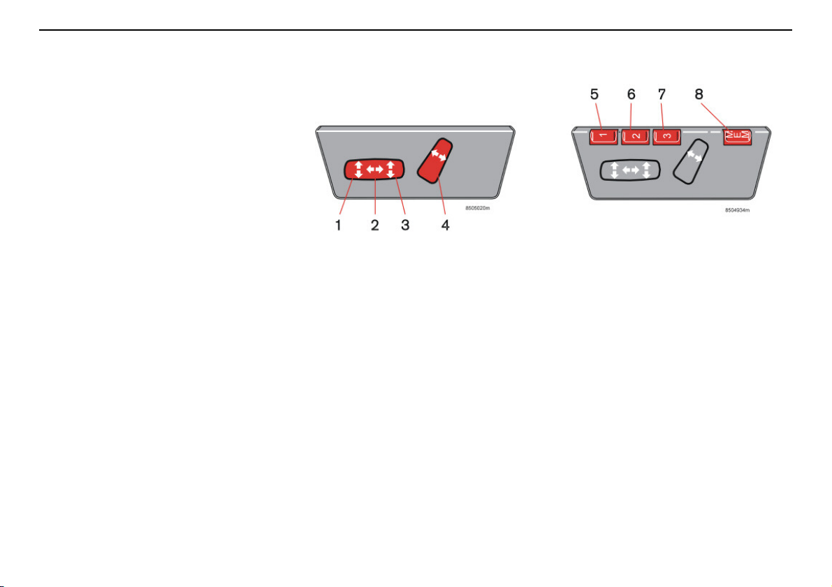
Front seats
Power seat (option)
Preparations
The seat is normally adjusted with the ignition
key is in position I or II. It can also be
adjusted within 4,5 minutes of the door being
unlocked with the key or remote control. If the
door is closed and the ignition key is not yet
in the ignition, or is in the 0 position, adjustments can be made within 40 seconds of the
door being closed.
Memory function in the remote control
(option)
The remote control used to unlock the car
stores information about the changes made
to the seat settings. When the car is next
unlocked with the same remote control and
the door is opened within five minutes, the
driver’s seat and the door mirrors assume the
stored positions.
Seat adjustment
The switches can be used to make the
following adjustments:
1. Front edge of seat cushion up/down
2. Seat forward/rearward
3. Seat up/down
4. Backrest rake
The seat can be moved in one direction at a
time. The power seats have an overload
protector that activates if a seat is blocked by
an object. If this occurs, switch offthe ignition
(position 0) and wait 20 seconds before
operating the seat again.
Interior
Seat with memory function
5. Setting seat and door mirrors,
program 1
6. Setting seat and door mirrors,
program 2
7. Setting seat and door mirrors,
program 3
8. Storing preset positions
Three positions can be stored. After
adjusting the seat, hold the MEM (8) button
depressed while pressing the button (5).
Further seat and door mirror settings can be
stored using memory buttons (6) and (7).
81
Page 83
Interior
WARNING!
Front seats
Setting preset positions
Press and hold one of the memory
buttons (5), (6) or (7) until the seat stops. If
you release the button, the seat stops
immediately for safety reasons.
Emergency stop
If the seat accidentally begins to move, press
one of the buttons to stop the seat.
Ensure that there is nothing in front of,
behind, or under the seat during
adjustment.
Ensure that none of the backseat
passengers will be trapped.
To avoid injury, ensure that children do not
play with the switches.
82
Page 84
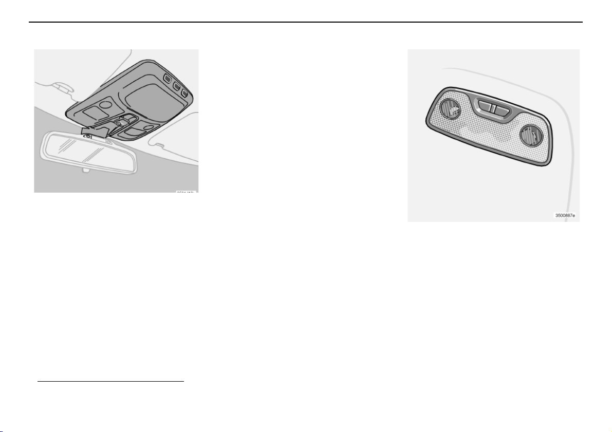
Interior lighting
General lighting
General lighting is activated and deactivated
by pressing the centre button. A brief press
on this button will switch general lighting on
or off in any situation. Activate and deactivate
general lighting by pressing the centre
button. General lighting comes on automati-
1
and remains lit for either 30 secondsor
cally
10 minutes when the engine is off.
General lighting comes on and remains lit for
30 seconds when you:
• when you unlock the car from the outside
using the key or remote control
• stop the engine and turn the ignition key
to position 0.
General lighting lights up and remains lit for
10 minutes when:
• one of the doors is open
• unless general lighting is switched off.
General lighting switches off:
• the engine is started
• you lock the car from outside using the
key or remote control.
General lighting can be switched on or off in
all situations by briefly pressing the button.
Unless switched off manually, general
lighting goes out automatically 10 minutes
after the engine is switched off.
You can switch off the timer by pressing the
button for more than 3 seconds. When you
then briefly press the button again, the timer
reconnects.
The pre-programmed times of 30 seconds
and 10 minutes can be modified. Contact an
authorised Volvo workshop.
Interior
Reading lamps
Reading lamps can be switched on or off by
pressing the respective button. For cars
seating seven, both reading lamps for the
third row of seats are switched on oroff when
one of the buttons is pressed. Unless
switched off manually, reading lamps are
switched off automatically 10 minutes after
the ignition is switched off.
1. The function is light-dependent and is
only activated when it is dark.
83
Page 85
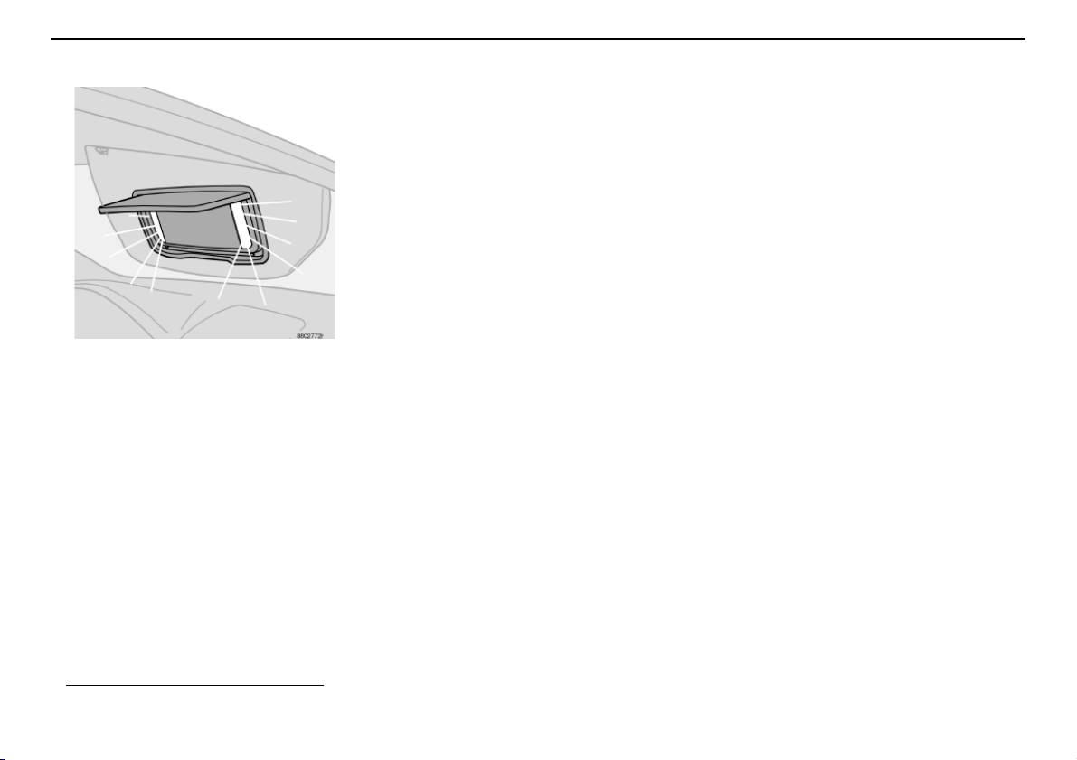
Interior
Interior lighting
Vanity mirror
The light comes on automatically when the
cover is lifted.
1. Option on certain markets.
84
1
Page 86
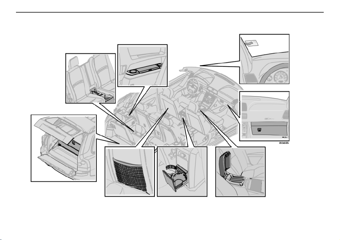
Storage spaces in the passenger compartment
1
2
3
4
5
6
7
8
Interior
85
Page 87
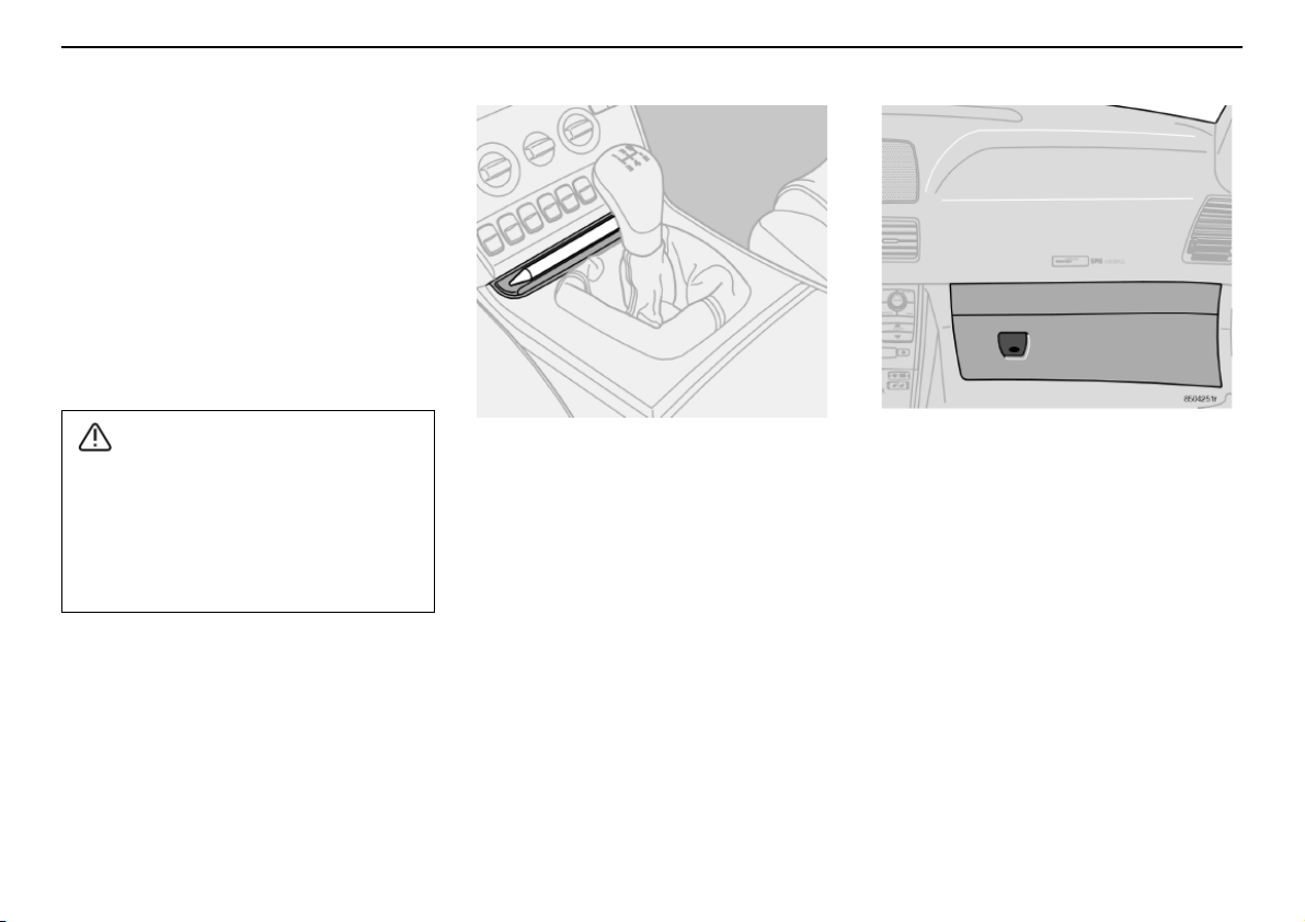
Interior
WARNING!
Storage spaces in the passenger compartment
Storage spaces
1. Storage compartment in third row of
seats.
2. Storage compartment and cup holder.
3. Ticket clip.
4. Glovebox.
5. Storage tray in centre console.
6. Cup holder for rear seat passengers.
7. Storage pocket (also on front edge of
the front seat cushions).
8. Grocery bag holder.
Ensure that no hard, sharp or heavy
objects lie or protrude in such a way that
they could cause injury during heavy
braking.
Always secure large and heavy objects
with a seatbelt or cargo retaining straps.
86
Pen holder
The centre console contains a pen holder.
Glovebox
The glovebox can be used to store things
such as the Owner’s Manual, maps, pens and
petrol cards.
Floor mats (option)
Volvo supplies floor mats specially manufactured for your car. These should be properly
anchored with the clips on the floor so they
do not slide and get jammed beside or under
the driver’s pedals.
Page 88
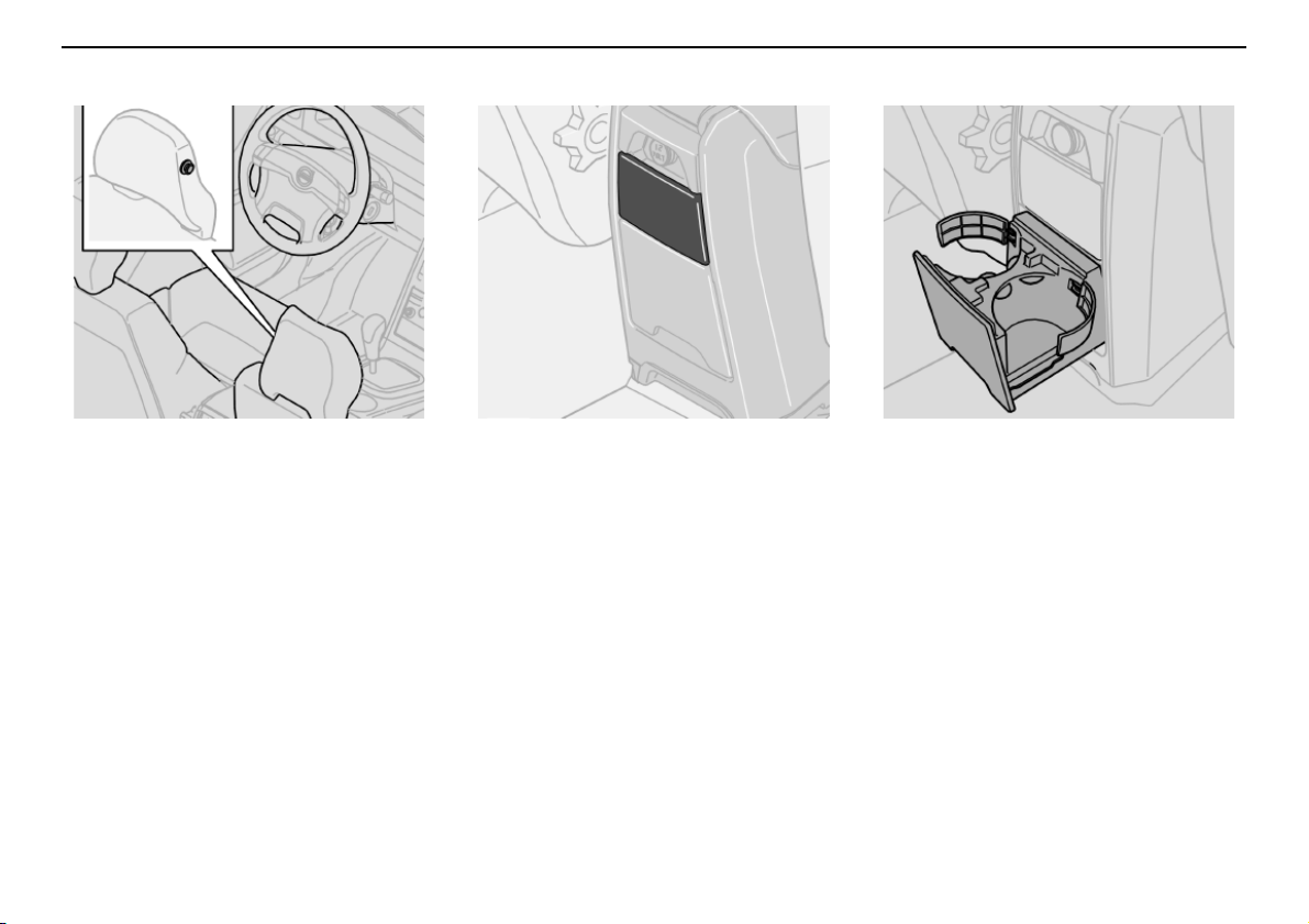
Storage spaces in the passenger compartment
Interior
Coat hanger
The coat hanger is only intended for light
garments.
Ashtray for rear seat passengers
(option)
Open the ashtray by pulling the top edge
outward.
To empty:
– Open the ashtray.
– Press the cover outwards and tip it back.
– Then lift it out.
Cup/bottle holder for rear seat
passengers
Pull the bottom edge of the insert to open.
The cup holder insert can be removed:
Detach the two clips so the holder can be
used for large bottles.
87
Page 89
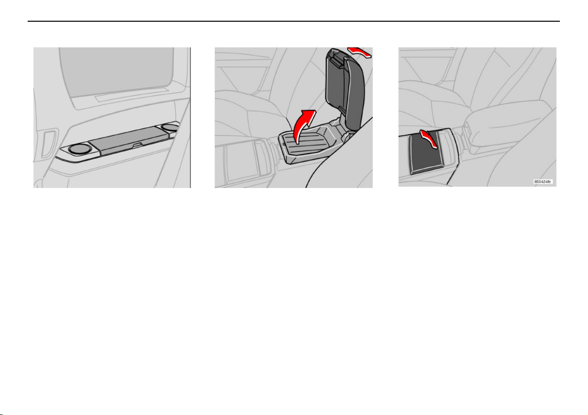
Interior
Storage spaces in the passenger compartment
Storage compartment and cup
holder (cars seating seven)
This storage compartment can be used for
CDs, books and the like.
88
Storage tray in centre console
The centre console contains a storage tray
for food and drinks, for example. The armrest
can be folded back to make a "table" for rear
seat passengers.
Under the storage tray is a storage
compartment, e.g. for CD discs.
Cup holder
Cup holder for front seat passengers.
Ashtray (option)
Pull out the insert to empty the astray.
Page 90
Storage spaces in the passenger compartment
Storage compartment in the
third row of seats (cars seating
seven)
This storage compartment can be used for
pens and other small items.
Interior
89
Page 91
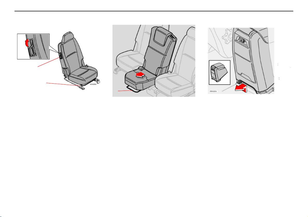
Interior
1
2
A
Rear seat
Rear seats – second row (cars
seating seven)
Lowering the backrest for entry into the
car
Lift the handle (1) up while pushing the
backrest forward.Do the reverse to return the
seat to its original position.
Adjusting the seat front - rear
Lift the bracket (2) to move the seat front or
back.
90
Sliding seat (cars seating seven)
The centre seat in the second row can be slid
farther forward than the other seats. Sliding
the seat completely forward improves
contact between a child sitting on the
integrated booster cushion and front seat
occupants.
Lift the bracket (A) to move the seat front or
back.
Removing the rear section of the
centre console
The centre console must first be removed if
you wish to slide the centre seat in the
second row forward.
– Remove the rear section of the centre
console by pulling the catch straight out
as illustrated above.
– Then lift the console out of the way.
Page 92
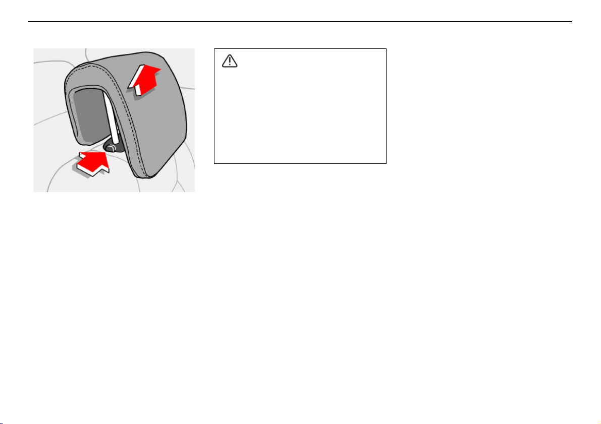
Rear seat
WARNING!
Head restraint, rear seat – centre
seat
The centre seat head restraint can be
adjusted to four different heights. Slide the
head restraint up as desired. Press in the
release button to lower it. See illustration!
Note that the head restraint cannot be
removed completely!
Interior
The lowest position should only be used
when the backrest is to be folded down or
when no one is sitting in this seat.
After raising the backrests in the second
and third row, it is important to make sure
that the backrests have locked into
position. Otherwise the protective system
of the seats may be compromised.
91
Page 93
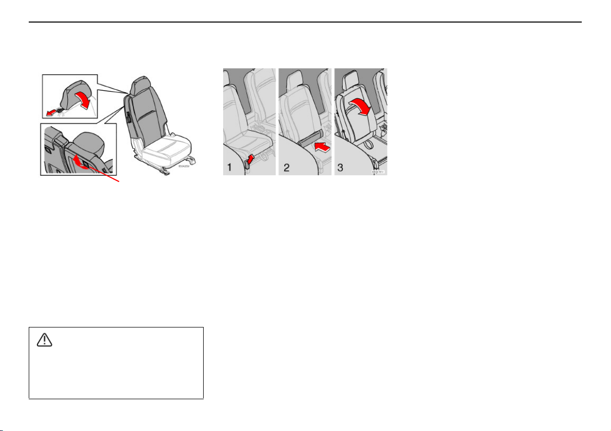
Interior
WARNING!
1
Cargo compartment
Repositioning the seats in the
third row
– Raise the backrest to its normal position.
– Take hold of the eyes and pull out the seat
cushion until you hear a click.
– Raise the head restraint.
The seat is now ready for use.
Extending the cargo
compartment – second row of
seats
– Set the seats in their rearmost positions
(applies only to cars seating seven).
– Lower the head restraint.
– Release the catch (1) and fold down the
backrest. Press down to lock the backrest
in its folded position.
For reasons of safety, no passengers
should sit in the third row of seats if the
outer head restraints in the second row
are lowered.
92
Extending the cargo
compartment – third row of seats
(cars seating seven)
Push the rear seats to the entrance/exit
position, see page 90.
1. Lift the handle upward.
2. Slide the seat cushion to its rearmost
position. Fold in the right and left-hand
cargo eyes in order to avoid damage
when lowering the backrest.
3. Fold down the backrest (The head
restraint folds in automatically when the
backrest is folded).
Page 94
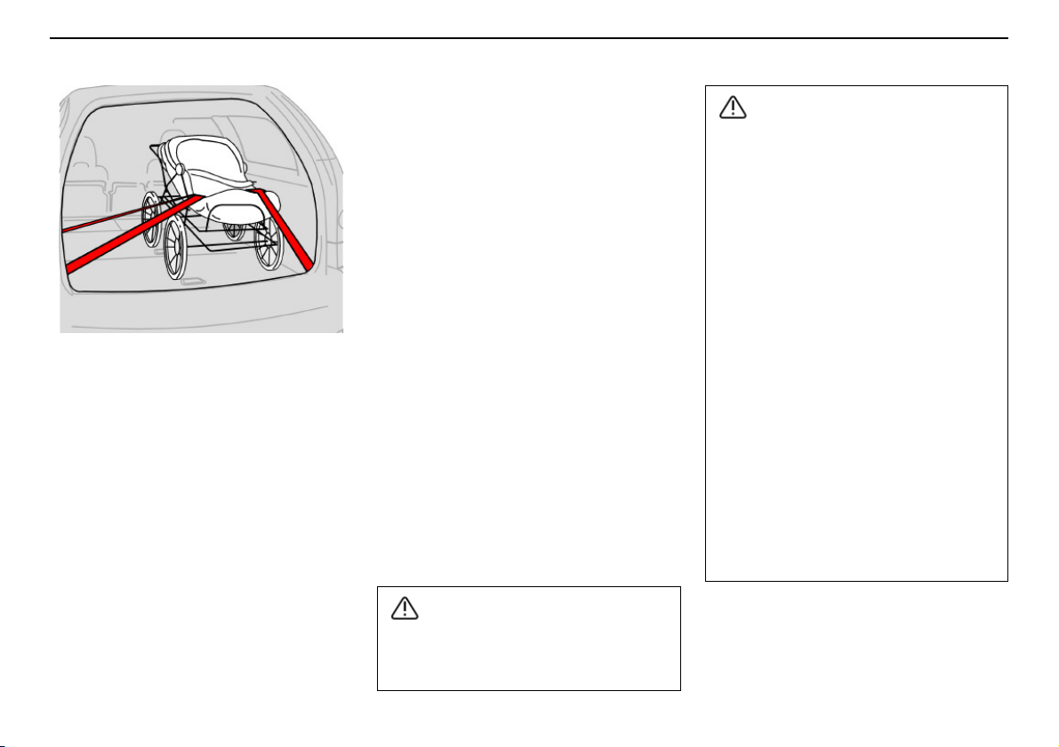
Cargo compartment
WARNING!
WARNING!
General
Payload depends on the car’s total kerb
weight, including any accessories that are
mounted. Kerb weight includes the driver, the
weight of the fuel tank when filled to 90 %
and various fluids, such as washer fluid and
coolant. Mounted accessories, i.e. towbar,
load carriers, space box, etc., are included in
the kerb weight.
The payload of the car is reduced by the
number of passengers and their weight.
Loading the cargo compartment
The seatbelts and airbags provide the driver
and passengers substantial protection,
especially in head-on collisions. However,
you must also remember to protect yourself
against injuries from behind. When loading
cargo, bear in mind that improperly secured
or incorrectly loaded objects in the cargo
compartment could be thrown forward with
great speed and force in the event of a
collision or sudden braking, causing serious
injuries.
Bear in mind that if an object weighing 20 kg
is subjected to a head-on collision at a speed
of 50 km/h, its impact weight will be
1000 kg.
Think about the following when loading:
• Do not load extremely heavy objects up
by the front seats. The lowered backrest
will be pressed down unnecessarily hard.
• Place the load by the backrest.
• Position heavy loads as low as possible.
• Position wide loads on each side of the
division in the backrest.
• Cover sharp edges with something soft.
• Secure the load with retaining straps
using the car’s lashing eyes.
• Never load above the backrest without a
load net.
The driving characteristics of the car
change based on the car’s kerb weight
and how heavily it is loaded.
Interior
Never load cargo above the backrests! If
you do so, the load could be thrown
forward in the event of sudden braking or
a collision and severely injure you or your
passengers. Remember to always secure
(bind) the load properly.
If the rear seat backrest is lowered, do not
load the car higher than 50 mm under the
top edge of the rear passenger windows.
Leave 10 cm of free space from the
windows inwards. Otherwise, the
intended protection of the inflatable
curtain, which is hidden in the headlining,
may be compromised.
Always secure the load. During heavy
braking the load may otherwise shift,
causing personal injury.
Turn off the engine and apply the parking
brake when loading or unloading long
objects! You may accidentally knock the
gear lever or gear selector with the load
and cause agear to engage and thecar to
move off.
93
Page 95
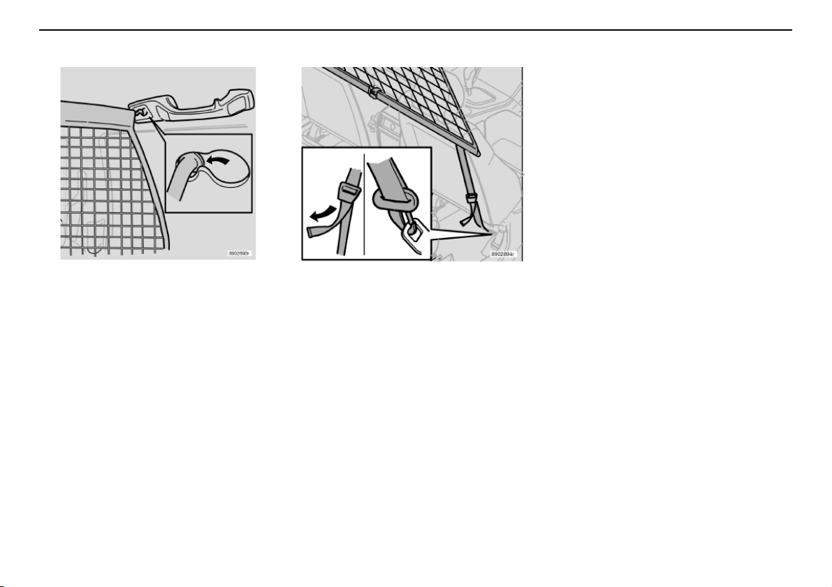
Interior
Cargo compartment
Only applies to cars seating seven:
– Make sure the net lies in front of the side
panel armrest when securing.
– Tension the safety net using the
anchoring straps.
Safety net
The safety net prevents luggage and cargo
from being thrown forward in the passenger
compartment during heavy braking.
The net is made of a strong nylon fabric and
can be secured two different ways:
– Behind the rear seat backrest.
– Behind the front seats if the rear seat is
lowered.
94
Fitting the safety net
If the car is equippedwith a cargo areacover,
remove it before fitting the safety net.
– Hook the upper rod in the front or rear
roof mounting.
– Hook the other end of the rod in the roof
mounting on the other side.
– Secure the safety net anchoring straps in
the eyes on the floor if the net is secured
in the rear roof mountings.
Use the eyes in the seat slide rail if the net
is secured in the front roof mountings.
Page 96
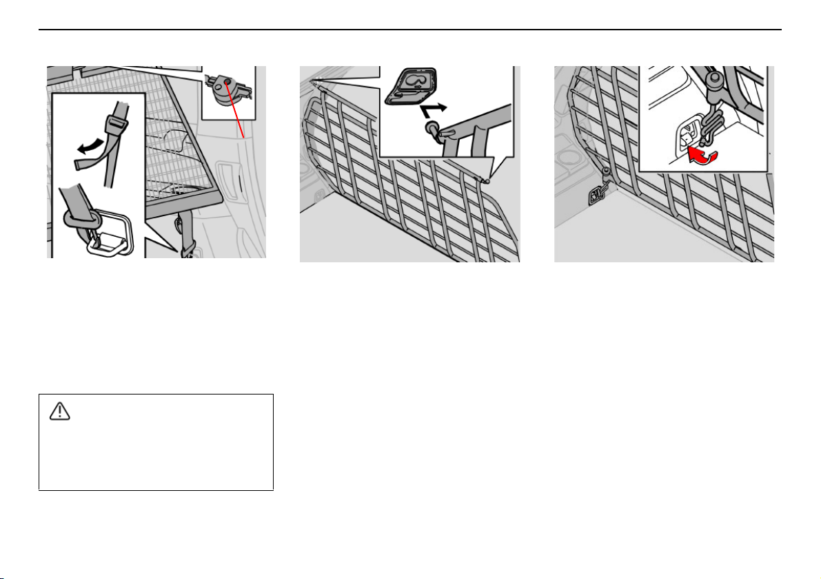
Cargo compartment
WARNING!
1
Interior
Folding up the safety net
The safety netcan be folded up and placed in
the cargocompartment floor (for cars seating
five).
Press the buttons (1) in the safety net hinges
to release the hinges and fold up the net.
Make sure that the upper mountings of the
safety net are correctly fitted and that the
anchoring straps are securely fastened.
Do not use a damaged net.
Steel safety grille (option)
The protective grille in the cargo
compartment prevents cargo or pets from
being thrown forward in the passenger
compartment in the event of heavy braking.
For reasons of safety, the protective grille
must always be mounted and secured
correctly.
Fit the protective grille as follows:
– Lift in the protective grille through the
tailgate opening or one of the rear
doorways (fold down the seats in the
second row if necessary).
– Insert one of the protective grille
mountings in its bracket above the rear
door behind the second row of seats.
– Slide the protective grille mounting to the
front position of the bracket.
– Place the other protective grille mounting
in its bracket above the other rear door
and slide it to the front position.
– Insert the attaching brace through the
lower mounting in the protective grille
from underneath, as indicated in the illustration.
– Fit the spring on the attaching brace and
screw in the knob.
95
Page 97
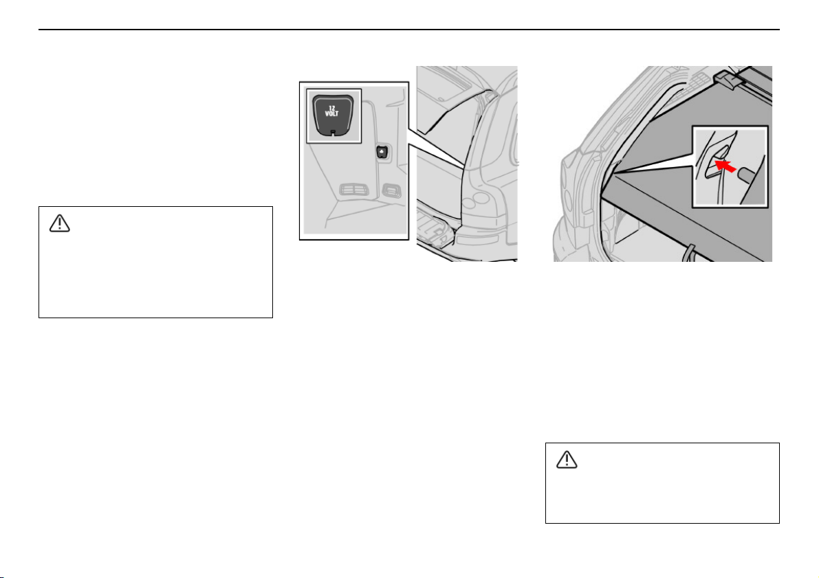
Interior
WARNING!
WARNING!
Cargo compartment
– Fit the attaching brace hook in the load
anchorage and tighten the knob until the
attaching brace takes hold in the load
anchorage.
– Do the same on the other side.
– Tighten both attaching braces alternately.
– Fit protective caps on the exposed screw
threads above the knobs.
For cars seating seven: For reasons of
safety, no passengers should sit in the
third row of seats if the protective grille is
positioned behind the second row of
seats.
Electric socket in the cargo
compartment
Slide down the cover when you wish to use
the socket. It works regardless of whetherthe
ignition is on or off.
If the ignition is switched off and a power
consumer that uses more than 0.1 A is
connected to the electric socket, a warning
message is shown on the display.
NOTE! Do not use the electric socket with
the ignition switched off as there is a risk of
the battery becoming discharged.
Cargo cover (option)
Pull out the cargo area cover, pull it over the
cargo and hook it into the holes in the rear
pillars of the cargo compartment.
Removing the cargo area cover
Press the end pieces of the cargo area cover
inwards, pull up and release. When fitting,
press the end pieces of the cargo area cover
down into the holders.
Do not place objects on the cargo area
cover. They could injure passengers
during braking or evasive manoeuvres.
96
Page 98
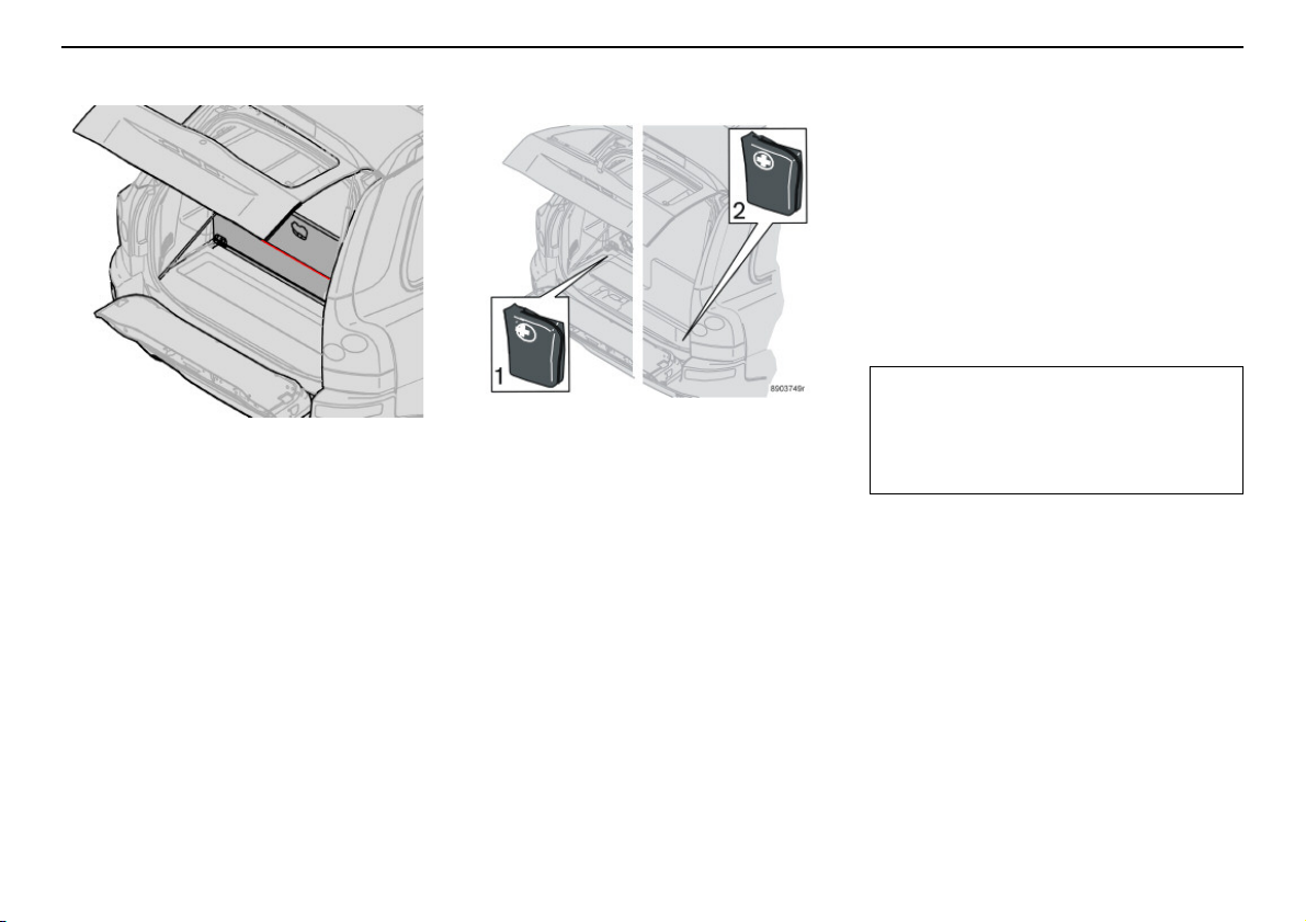
Cargo compartment
IMPORTANT!
Interior
Opening the compartment in the
cargo compartment floor (cars
seating seven)
– Lift up the cover.
If the car is equipped with a grocery bag
holder:
– Open the upper cover, detach the
tensioning straps to the grocery bag
holder, if fitted, and open the lower cover.
Grocery bag holder
Open the tailgate. Hang or secure your
grocery bags using the tensioning straps or
holders.
1. Cars seating five 2. Cars seating seven
Opening the compartment in the
cargo compartment floor (cars
seating five)
– Lift up the cover in the cargo
compartment floor.
If the car is equipped with a grocery bag
holder:
– Lift the cover, detach the tensioning
straps to the grocery bag holder.
Remember not to put anything in the area
the cushions fold into. The cushions and
seat mechanisms could be damaged.
Cargo area compartment,
contents
The following is housed in the floor
compartment:
• Warning triangle (certain markets)
• Tool kit
• First-aid kit (certain markets)
• Jack (alternative location)
NOTE! Some components of the first-aid kit
have an expiration date and should be
replaced before this date.
97
Page 99

Interior
98
Page 100

Locks and alarm
Keys and remote controls 100
Locking and unlocking 103
Child safety locks 106
Alarm (option) 108
99
 Loading...