

Page 1

2005 Volvo XC70 L5-2.5L Turbo VIN 59 B5254T2 Copyright © 2011, ALLDATA 10.40 Page 1
N
gg
gggggggggggggggggggggg
Vehicle: Description and Operation
Service Information Notes
Manual
About this manual
The instructions in this manual are designed as support for mechanics with basic training as per Volvo's competence standard.
It is extremely important that the user of the instructions first read through the general safety instructions tied to most function groups.
Writer philosophy
As of 2006, a new writer philosophy has been introduced to the instructions in the mechanic section. In previous instructions, detailed text was
written and supplemented with figures. In the new method, we do the opposite.
From 2006, the instruction focuses on the figure and text is only used when it is impossible to show the complete work method in figures.
Warning texts indicate any hazards applicable to a procedure. Warnings mean risk of personal injury if the instructions are not followed.
Caution texts indicate that there is a risk of damage to the vehicle or equipment if the instructions are not followed.
ote texts provide important additional information that is required in order to carry out a repair.
Environment
Always follow local safety regulations when disposing of environmentally hazardous waste or pyrotechnic (SRS) components.
Technical content
Illustrations in the information may be reused from previous models and may therefore deviate as regards the background's motif. The technical
content relevant to the operation is, however, always correct.
Screws coated with friction-generating or sealing elements as well as lock nuts are screws used with lock nuts shall always be replaced unless the
instructions specify reuse of the original screw or nut.
Screws or nuts that have been angle-tightened shall always be replaced with a new one.
Gaskets and O-rings shall always be replaced unless the instructions specify reuse of the original gasket or O-ring.
A new decal shall always be affixed after replacement of a component with safety decal. No decals may be painted or permanently covered in any
other way.
All tools and equipment used in the instructions are in Volvo's aftermarket standard (A10 - Tools, Equipment & Information). (E10=English,
A10=Swedish).
The instruction shall contain links to or all necessary information to perform the operation in a manner that ensures quality and personal safety.
If the spare part is a repair kit, the entire contents of the kit shall be used.
Links
The philosophy is to avoid having information on a specific component in more than one spot in the system. To do so, the instructions often use
links that take the user directly to the correct information for the component to which the link refers.
After having followed one or more links and carried out the respective measure, the user can always return to the previous method by using VIDA's
"Back" function.
Page 2
2005 Volvo XC70 L5-2.5L Turbo VIN 59 B5254T2 Copyright © 2011, ALLDATA 10.40 Page 1
gg
gggggggggggggggggggggg
Vehicle: Description and Operation
Symbols in Service Information
Symbols
Symbols
Symbols are used to supplement or provide further details about the procedure.
Symbols contribute to reducing the amount of text. These are designed to be easy to understand and prevent misunderstandings.
In order to clarify the meaning of the symbols an explanation is also provided.
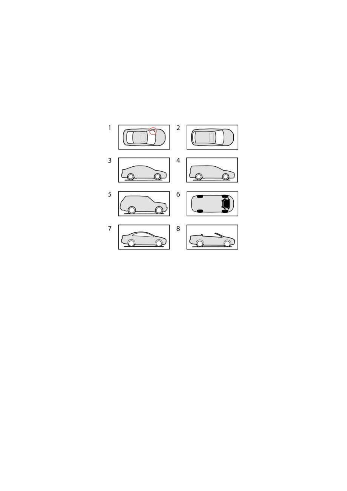
Localization symbols
Localization symbols are used to simplify localization in the procedure.
As the images are reused, the silhouette may not correspond with the selected vehicle model.
1. Sedan/coupe/convertible view from above. A red circle or a line indicates a focused area.
2. Station wagon, SUV, view from above
3. Sedan, view from side
4. Station wagon, view from side
5. SUV, view from side
6. View from below
7. Coupe/convertible, view from the side (roof closed)
8. Convertible, view from the side (roof open)
Tools
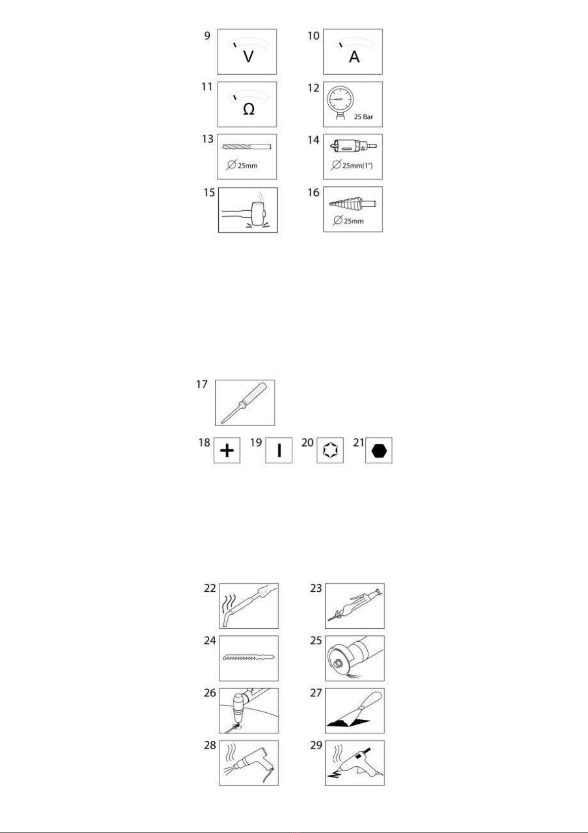
The symbols denote that a specific measurement instrument or tool is recommended for the working procedure.
Page 3
2005 Volvo XC70 L5-2.5L Turbo VIN 59 B5254T2 Copyright © 2011, ALLDATA 10.40 Page 2
gg
gggggggggggggggggggggg
9. Use a Voltmeter
10. Use an Ammeter
11. Use an Ohmmeter
12. Use a pressure gauge, the value states the target value
13. Use a drill with the stated size
14. Use a hole saw with the stated size
15. Use an appropriate impact tool
16. Use a step drill, drill to the stated size
17. Use a suitable screwdriver. The symbol is used together with one of the different head types below.
18. Crosshead screw
19. Slot screw
20. Torx screw
21. Socket head cap screw
Page 4
2005 Volvo XC70 L5-2.5L Turbo VIN 59 B5254T2 Copyright © 2011, ALLDATA 10.40 Page 3
gg
gggggggggggggggggggggg
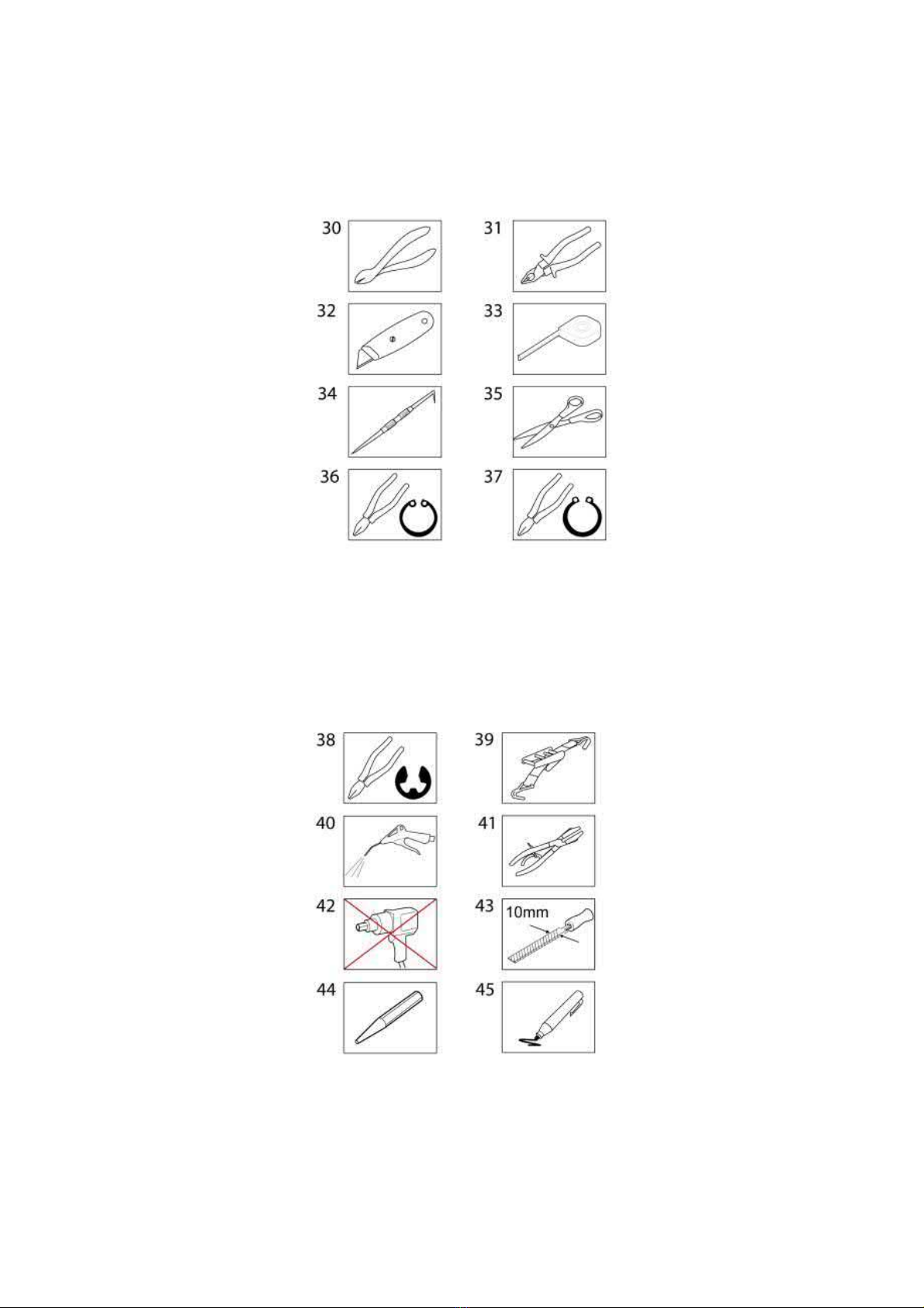
22. Use a soldering iron/soldering pen
23. Use a keyhole saw
24. Saw
25. Use a cutting disc/grinding disc
26. Use a plasma cutter
27. Scrape off
28. Use a hot-air gun
29. Use hot-melt adhesive
30. Use suitable nippers
31. Use suitable pliers
32. Cut
33. Measure
34. Scribe/mark up
35. Cut
36. Use suitable pliers for internal circlips
37. Use suitable pliers for external circlips
38. Use suitable tool to remove/install the retainer rings
39, Use a load strap
40. Blow clean using compressed air
41. Use pliers
42. Do not use impact screwdriver/wrench
43. Use a 10 mm wide file
44. Use driver punch
45. Mark using a pen
Materials:
Page 5
2005 Volvo XC70 L5-2.5L Turbo VIN 59 B5254T2 Copyright © 2011, ALLDATA 10.40 Page 4
gg
gggggggggggggggggggggg
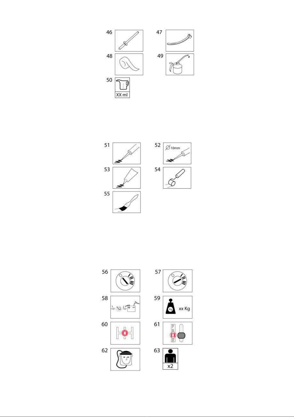
The symbols indicate that some form of material is to be used in the procedure.
46. Use a pop rivet
47. Use a cable tie
48. Use tape
49. Use oil for lubrication
50. Add a liquid, the type of liquid is indicated by the context or is stated in the procedure.
51. Apply, what is to be applied is evident from the context.
52. Apply to a diameter stated in the image, what is to be applied is evident from the context.
53. Apply, what is to be applied is evident from the context.
54. Apply using a roller, what is to be applied is evident from the context.
55. Apply using a brush, what is to be applied is evident from the context.
Other symbols
56. Ignition off, ignition to the 0 position
57. Ignition on, ignition to the 2 position
58. Disconnect the battery negative terminal
59. Add pressure with the stated number of kg
Page 6
2005 Volvo XC70 L5-2.5L Turbo VIN 59 B5254T2 Copyright © 2011, ALLDATA 10.40 Page 5
gg
gggggggggggggggggggggg
60. Engage the stated gear position, manual transmission
61. Engage the stated gear position, automatic transmission
62. Use a fresh air mask
63. Two people are required for this task.
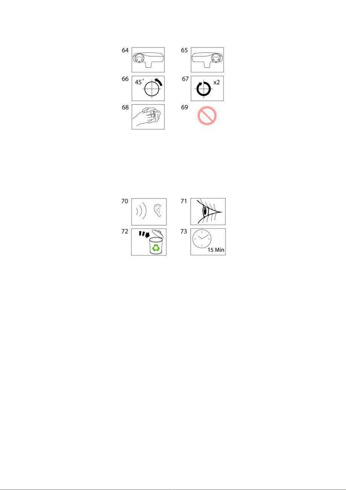
64. Applies to left-hand drive vehicles. The symbol can also be used as a localization symbol, then with a red ring or a line in the symbol.
65. Applies to right-hand drive vehicles. The symbol can also be used as a localization symbol, then with a red ring or a line in the symbol.
66. Turn the component XX degrees in the direction of the arrow, the number of degrees is evident from the image.
67. Rotate the component XX turns in the direction of the arrow, the number of turns is evident from the image.
68. Wipe off
69. Used in combination with other symbols and then has the meaning "do not use XX"
70. Listen for noise
71. Check/Ensure
72. Component is used. Replace with new
73. Wait the specified time
Page 7
2005 Volvo XC70 L5-2.5L Turbo VIN 59 B5254T2 Copyright © 2011, ALLDATA 10.40 Page 1
gg
gggggggggggggggggggggg
Vehicle: Description and Operation
Screwed Joint, Torque/Angle Tightening
Screwed joint, torque/angle tightening
Special tools:
951 2050 BEVEL PROTRACTOR See: Tools and Equipment/951 2050 Bevel Protractor
Screwed joint
There are a great number of torque spanner systems available on the market where the spanner grip can be replaced with other types. These wench
grips are normally ideally suited to torque tightening screwed joints in poorly accessible places.
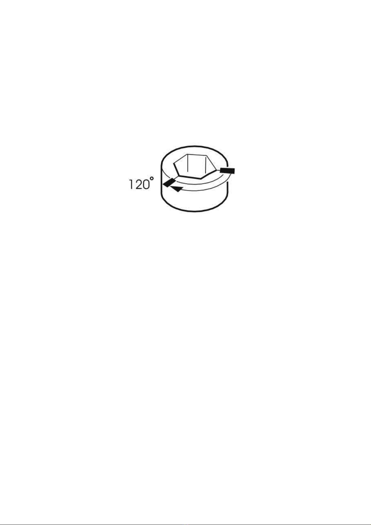
There may be occasions when torque tightening of a screwed joint must be followed by angle tightening and space does not allow the use of
protractor (part number 951 2050 BEVEL PROTRACTOR See: Tools and Equipment/951 2050 Bevel Protractor ). In these cases, use either a nut,
a screw head or a tool. These are usually hexagonal and each corner is
. If there are twelve edges, each corner is
°
60
30°
.
To angle tighten, mark the material and nut for example as illustrated and then tighten so that the markings are opposite each other.
Page 8
2005 Volvo XC70 L5-2.5L Turbo VIN 59 B5254T2 Copyright © 2011, ALLDATA 10.40 Page 1
gg
gggggggggggggggggggggg
Vehicle: Description and Operation
Images in Service Information
Images
Image philosophy
A new image philosophy has been introduced in 2006 for instructions in mechanical working procedures. In previous instructions a detailed text
was supplemented with images.
In the new instructions it is the opposite.
From 2006 the instructions focus on images and text is only used where it is not possible to show the entire working procedure in images.
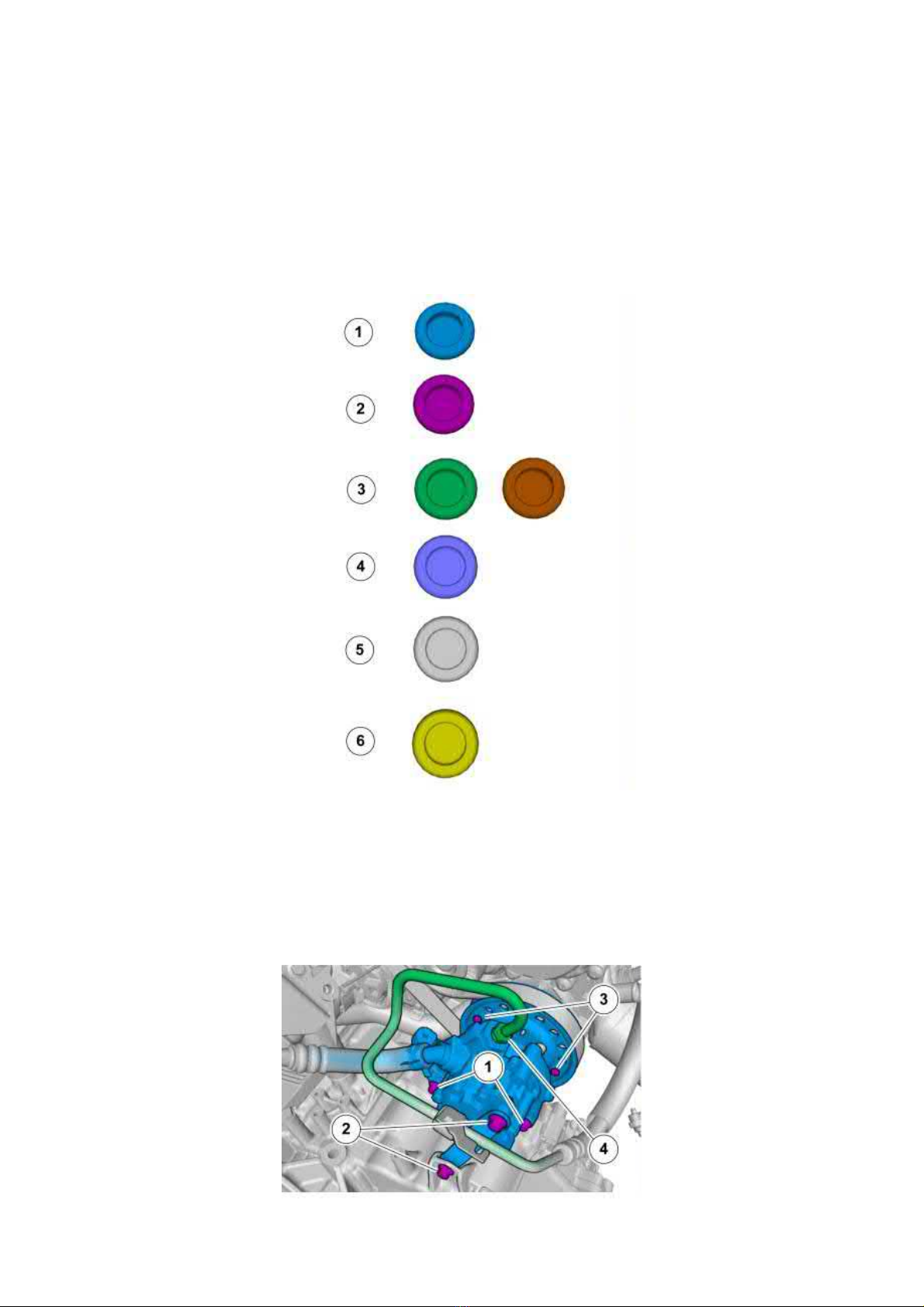
Color symbols
1. Used for focused component, the component with which you will do something.
2. Used for retaining elements or components to be removed/installed. Can be screws, clips, connectors, etc.
3. Used as extra colors, which needed to show or differentiate additional components.
4. Used for standard tools and special tools.
5. Used as background color for vehicle components.
6. Used when the component is not fully removed from the vehicle but only hung to the side.
Order number
A figure in a circle denotes the order in which the different stages in the image are to be carried out.
Page 9
2005 Volvo XC70 L5-2.5L Turbo VIN 59 B5254T2 Copyright © 2011, ALLDATA 10.40 Page 2
gg
gggggggggggggggggggggg
Types of arrows
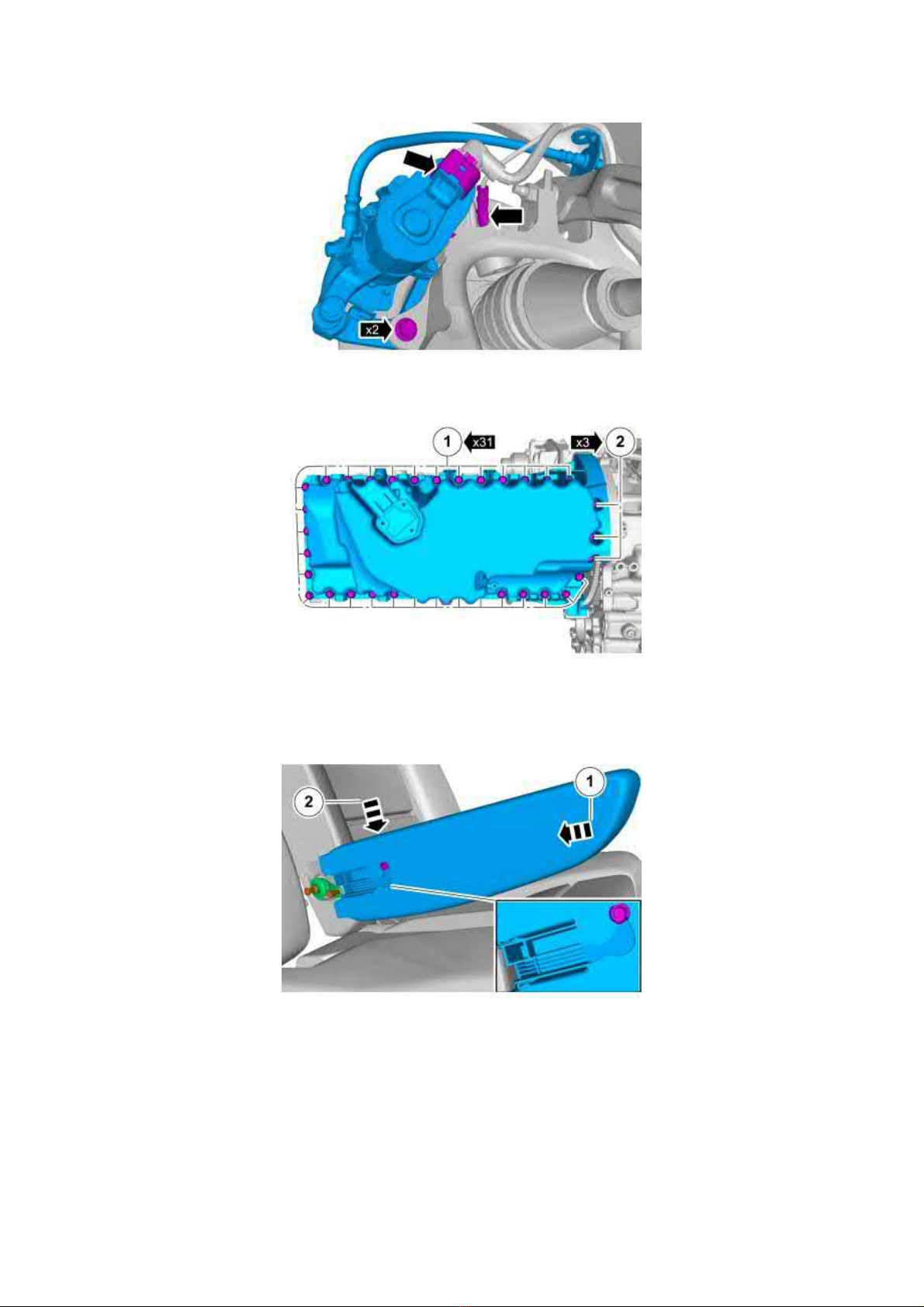
Identification arrows
Arrows that identify parts to be removed.
The numbered arrow denotes that they are two screws to be removed to release the brake caliper.
The numbered arrow denotes the number of retaining elements to be removed
All retaining elements embraced by a numbered arrow are of the same type and size.
Movement arrows
Movement arrows indicate pushing or pulling in the direction of the arrow.
In this instance the movement arrows are numbered to denote the order in which you should push or pull the component.
Page 10
2005 Volvo XC70 L5-2.5L Turbo VIN 59 B5254T2 Copyright © 2011, ALLDATA 10.40 Page 3
gg
gggggggggggggggggggggg
Rotation arrows denote that the component must be turned in the direction of the arrow.
The rotation arrow indicates that you should turn the component to release it.
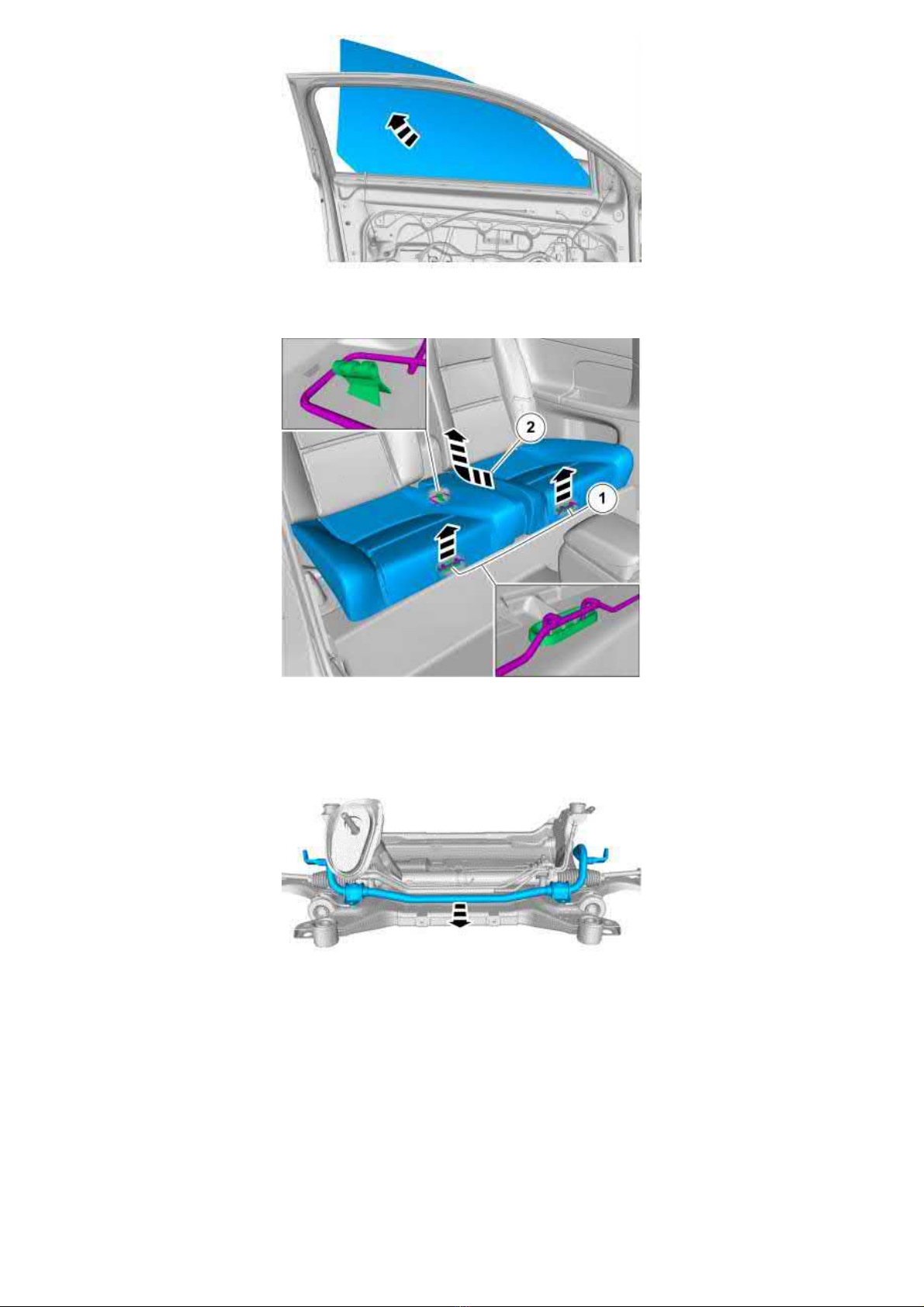
Angled movement arrows denote that the component should first be moved in one direction, and then in another direction.
The angled arrow (2) shows that you should first push the cushion backward and then upward to release it.
Background components
Background components are often taken away in order to improve the clarity of an image.
Parts that are not relevant in order to put across the instructions in the image have been omitted.
Views
Page 11
2005 Volvo XC70 L5-2.5L Turbo VIN 59 B5254T2 Copyright © 2011, ALLDATA 10.40 Page 4
gg
gggggggggggggggggggggg
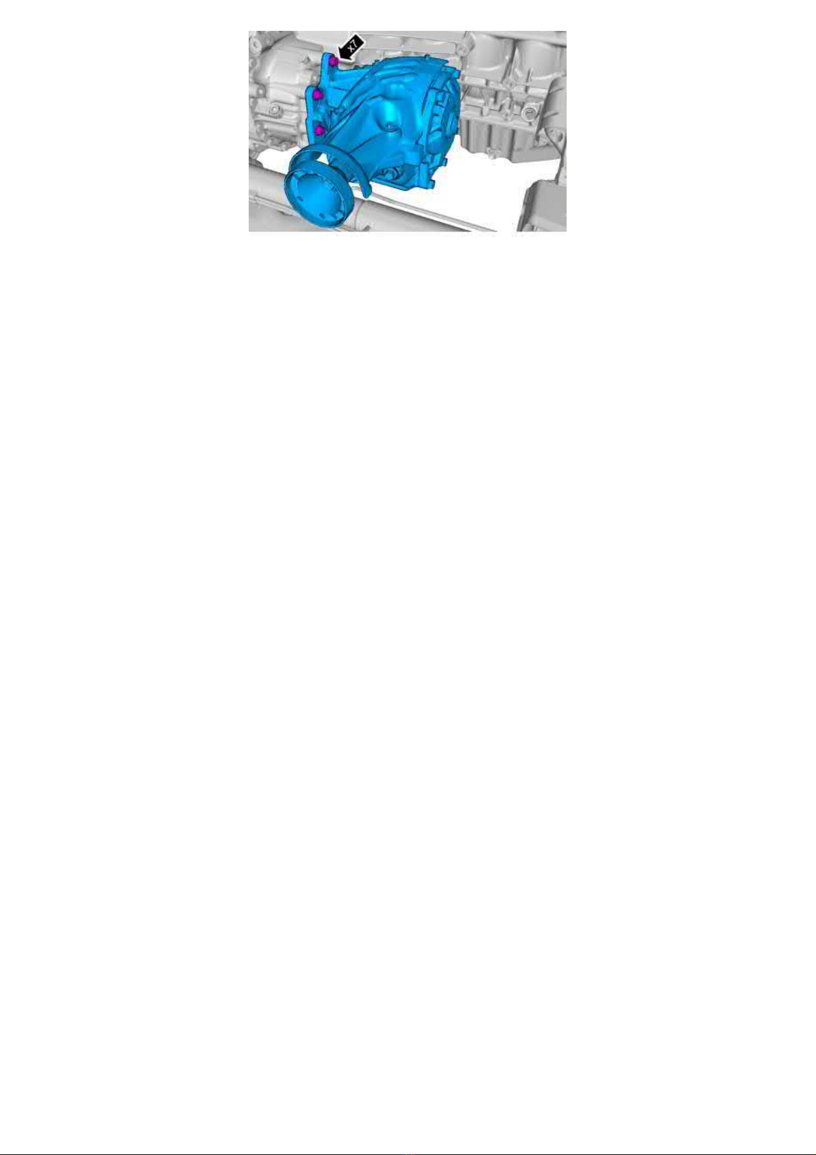
Views are sometimes chosen that show components from another angle and which do not correspond with how you see the components when
working on the car to make the images clearer. For example, this is done to show concealed screws.
When working on the bevel gear it is possible that you see it from this angle when installed in the car.
Page 12
2005 Volvo XC70 L5-2.5L Turbo VIN 59 B5254T2 Copyright © 2011, ALLDATA 10.40 Page 1
gg
gggggggggggggggggggggg
Vehicle: Service and Repair
Control modules
Connecting and disconnecting control modules
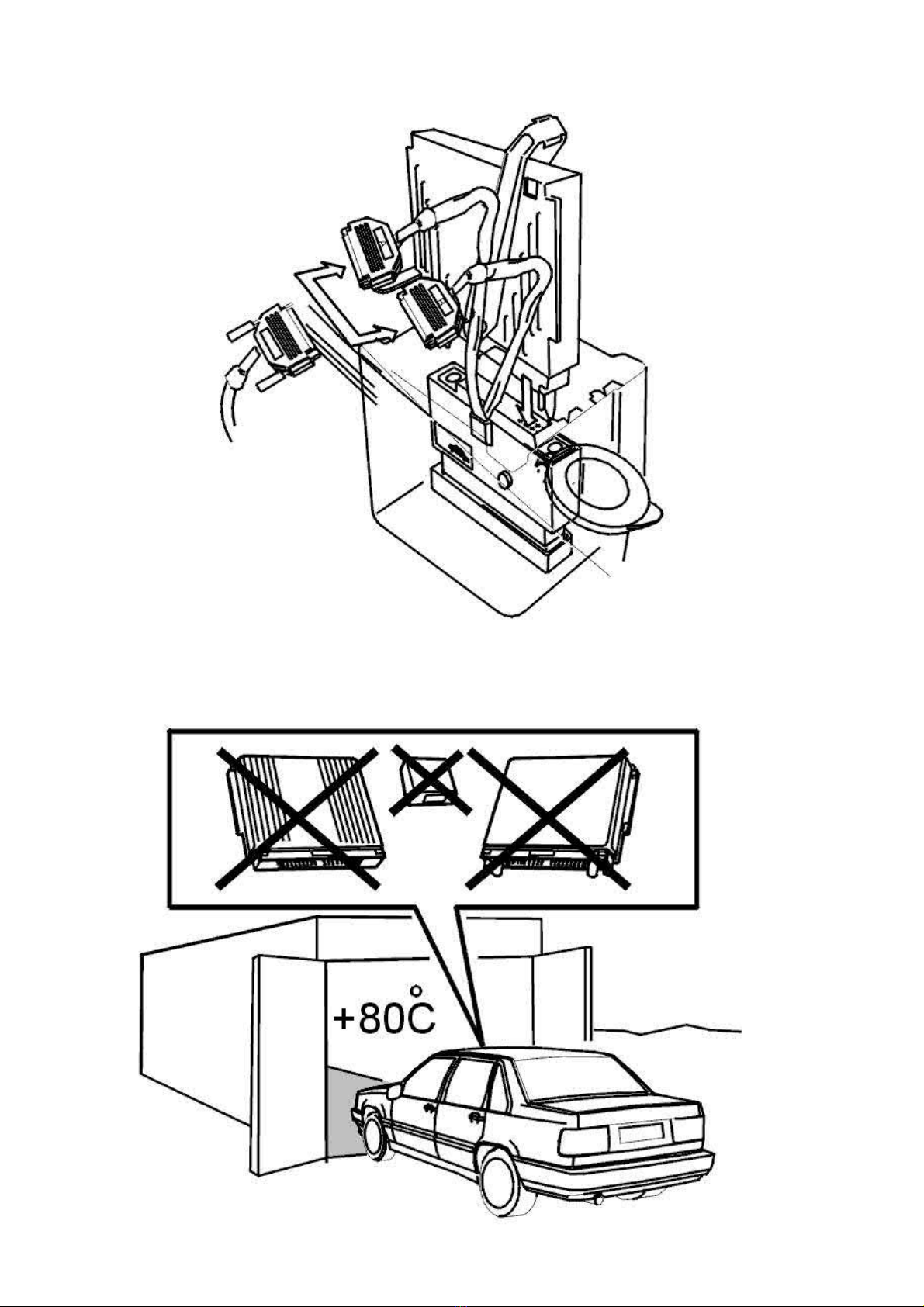
Always switch off the ignition before connecting and disconnecting control modules, connectors and the breakout box.
The ignition must be switched off when taking readings with an ohmmeter.
Temperature
Page 13

2005 Volvo XC70 L5-2.5L Turbo VIN 59 B5254T2 Copyright © 2011, ALLDATA 10.40 Page 2
gg
gggggggggggggggggggggg
The control modules must not be heated to above 80°C. Remove control modules when stoving for example.
Arc welding
Always disconnect the battery negative lead to prevent a short-circuit.
Position the welding ground as close to the welding site as possible, otherwise different ground potentials may be generated in different
components.
When welding close to an electronic module, the unit
Replacement
Do not replace a control module without checking its wiring and components. Otherwise the new component may be damaged in the same way as
the old one.
be removed to avoid heat damage.
must
Page 14
2005 Volvo XC70 L5-2.5L Turbo VIN 59 B5254T2 Copyright © 2011, ALLDATA 10.40 Page 1
gg
gggggggggggggggggggggg
Engine: Removal and Replacement
Engine/Transmission, Installing
Engine/transmission, installing
Special tools:
951 2050 BEVEL PROTRACTOR See: Tools and Equipment/951 2050 Bevel Protractor
999 5972 FIXTURE See: Tools and Equipment/999 5972 Fixture
Note! As the illustrations in this service information are used for different model years and / or models, some variation may occur.
However, the essential information is always correct.
Note! For tightening torques, see Tightening torque See: Specifications/Tightening Torque
Note! To ensure that there is no exhaust leakage, see: Flanged joint, assembling See: Exhaust System/Exhaust Pipe/Service and Repair.
Installing the engine and transmission unit
Raise the engine and the transmission unit. Use a lifting table with locating pins.
Stop when the sub-frame is approximately 15 cm below the frame members.
Install (left and right-hand sides)
- the drive shaft to the hub. Install the center screws.
- the ball joint to the control arm. Install the nuts.
Note! Ensure that the mating surfaces on the ball joints and control arms are clean.
Twist the engine block heater (option) into position. Check that the air conditioning (A/C) compressor is correctly positioned.
Check that the tie rod is in the correct position. Check that the transmission cable is routed between the steering shaft and the firewall.
Align the steering shaft joint on the steering gear.
Lift the engine and transmission unit up to the frame members.
Do not tighten yet!
Do not tighten yet!
Note! Ensure that no hoses, wiring or anything else catches.
Page 15
2005 Volvo XC70 L5-2.5L Turbo VIN 59 B5254T2 Copyright © 2011, ALLDATA 10.40 Page 2
gg
gggggggggggggggggggggg
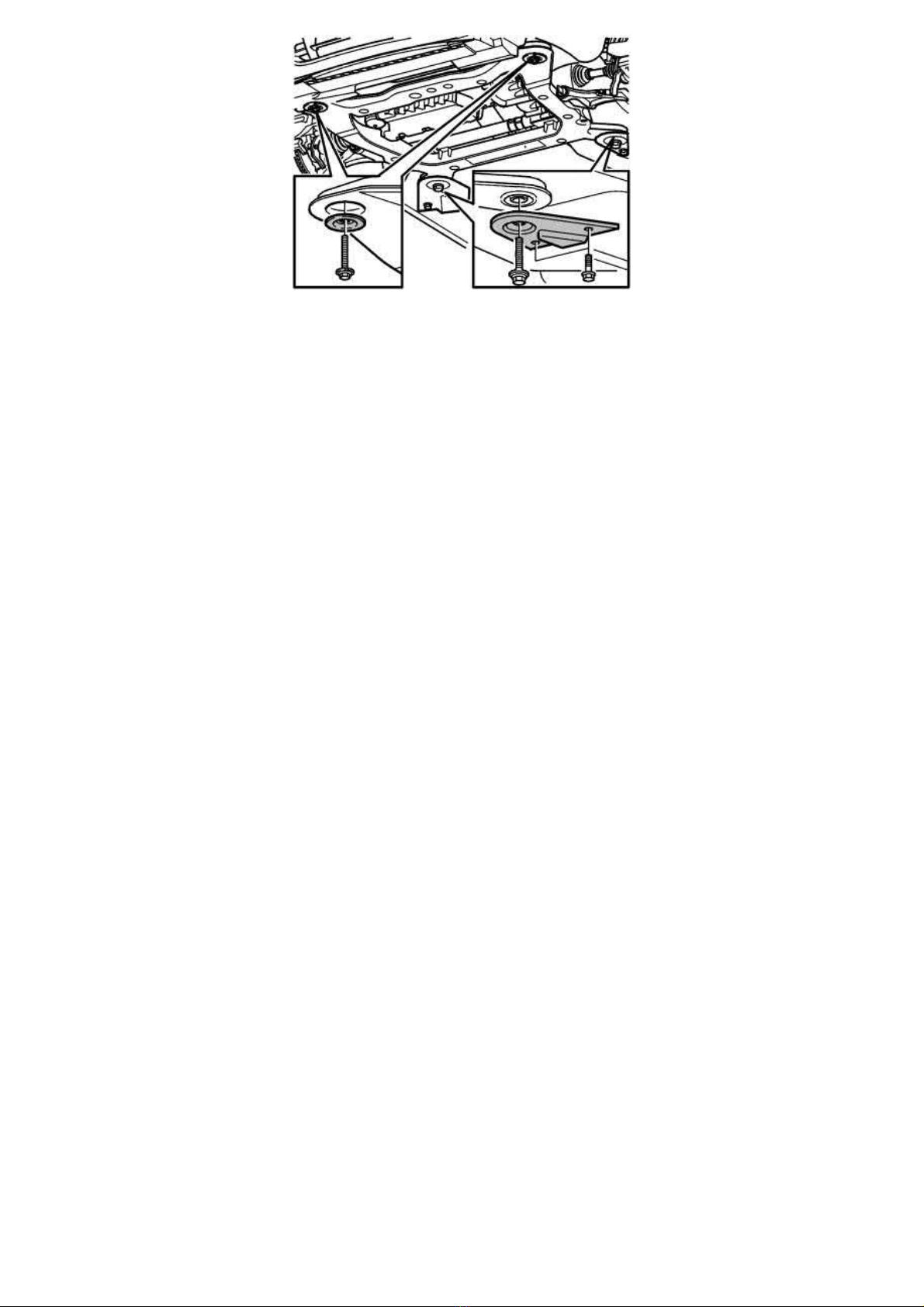
Install
- a new screw in the lower steering shaft joint. Tighten to
- new screw in the sub-frame. Lubricate the screws
- the washes at the front edge and the support plates at the rear edge of the sub-frame.
20 Nm
Tighten the screws for the sub-frame. Tighten to
and Equipment/951 2050 Bevel Protractor. Start on the left hand side of the sub-frame. Continue with the right hand side.
Tighten the screws for the brackets at the rear of the sub-frame. Tighten to
Remove the lifting table.
Installing the propeller shaft (all-wheel drive (AWD) only)
Install the propeller shaft (all-wheel drive (AWD) only). See Pinion seal bevel gear, replacing See: Transmission and Drivetrain/Automatic
Transmission/Transaxle/Seals and Gaskets/Service and Repair/Pinion Seal Bevel Gear, Replacing.
Installing the three-way catalytic converter (TWC) (all-wheel drive (AWD) only)
Lubricate the studs where the exhaust system separates downstream of the three-way catalytic converter (TWC). Use paste 116 1408.
Warning! Avoid skin contact with the paste.
Lift up the exhaust system and connect it to the rear system. Use a new gasket and new nuts.
Use a mobile jack with universal plate 999 5972 FIXTURE See: Tools and Equipment/999 5972 Fixture as a support.
Hint:
Note! The routing of the heated oxygen sensor (HO2S) wiring over the brake pipe.
Install the screws holding the SIPS member to the bodywork. Tighten the screws.
Press the brake pipe into place in the holders on the SIPS member.
Installing the front exhaust pipe
105 Nm
. Angle-tighten
. Use bevel protractor 951 2050 BEVEL PROTRACTOR See: Tools
120°
.
50 Nm
Lubricate the studs on the turbocharger (TC). Use paste 116 1408.
Warning! Avoid skin contact with the paste.
Install the front exhaust pipe on the turbocharger (TC). Use new nuts. Tighten to
Clamp the wiring for the rear heated oxygen sensor (HO2S) into place at
- the bracket at the rear of the sub-frame
- the clips on the power steering pipe at the steering gear
- the clamp at the right-hand side of the steering gear.
Connecting fuel lines
30 Nm
.
Page 16
2005 Volvo XC70 L5-2.5L Turbo VIN 59 B5254T2 Copyright © 2011, ALLDATA 10.40 Page 3
gg
gggggggggggggggggggggg
When assembling the fuel lines, see also: Fuel system, quick-release connectors See: Powertrain Management/Fuel Delivery and Air Induction/Fuel
Line Coupler/Description and Operation.
Connect the quick-release connector and the fuel line to:
- the motor
- the engine block heater (option).
Press the EVAP line together at the rubber joint.
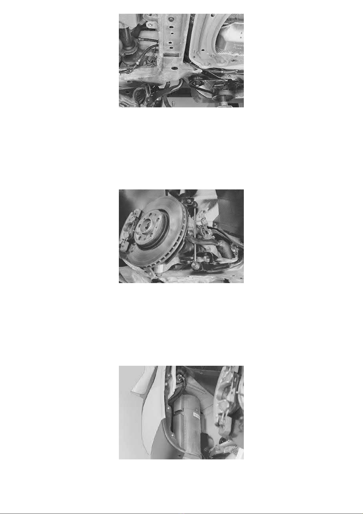
Assembling the spring strut
Install
- the tie rods. Use new nuts. Tighten to
- the link rod to the anti-roll bar. Use new nuts. Tighten to
- the bracket for the brake pipe to the body.
Tighten
- the nut for the ball joint and control arm. Tighten to
- the center screw in the drive shaft. Tighten to
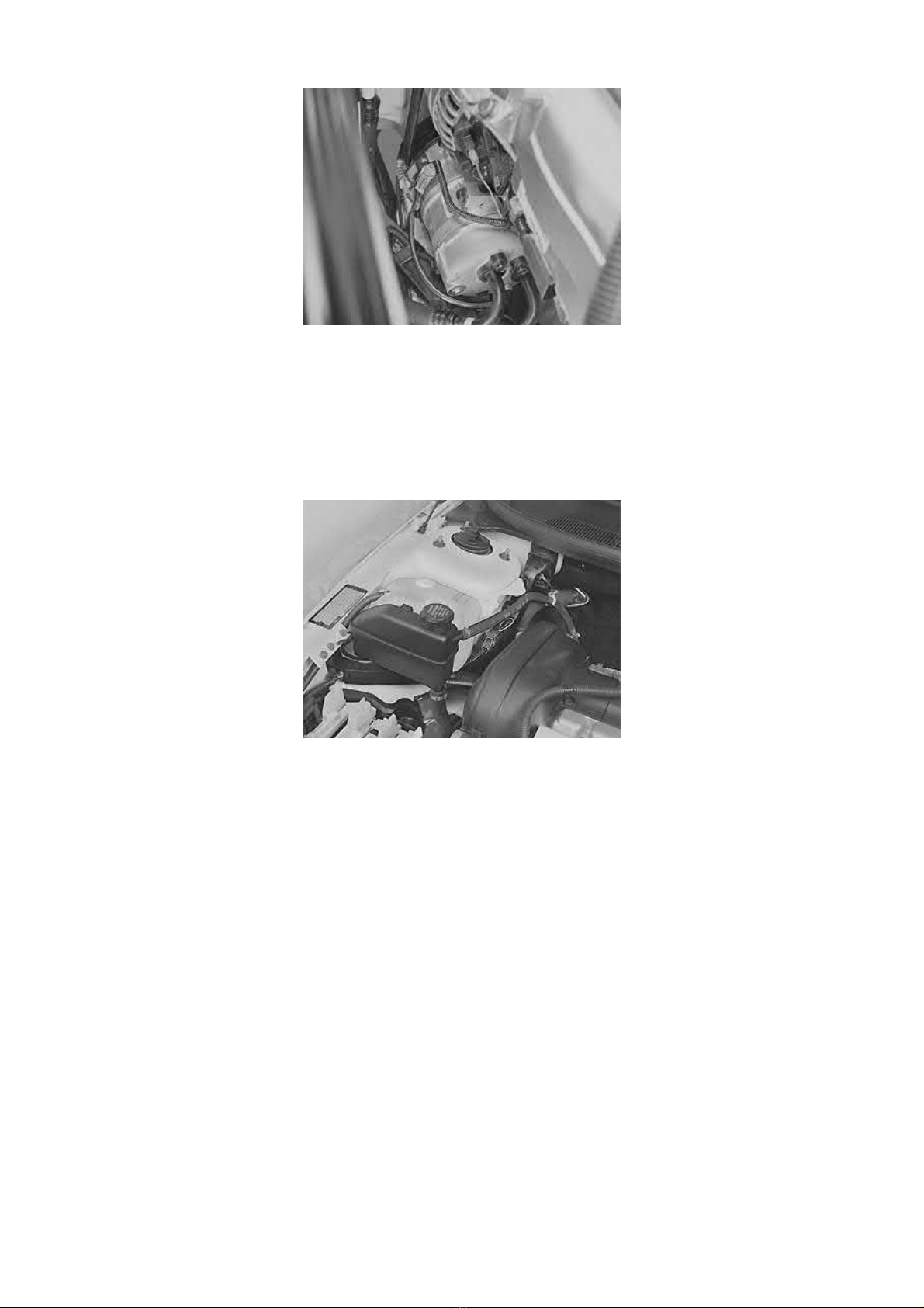
Cars with engine block heaters (option)
Connect the heater connector at the vehicle wiring.
Ensure that the connector and wiring are secured at the body.
Rivet the fender liner to the fender edge.
Check that the quick-release fuel line connector is secure at the engine block heater.
70 Nm
80 Nm
50 Nm
. Counterhold with Tx27
50 Nm
. Counterhold using Tx40
.
Page 17
2005 Volvo XC70 L5-2.5L Turbo VIN 59 B5254T2 Copyright © 2011, ALLDATA 10.40 Page 4
gg
gggggggggggggggggggggg
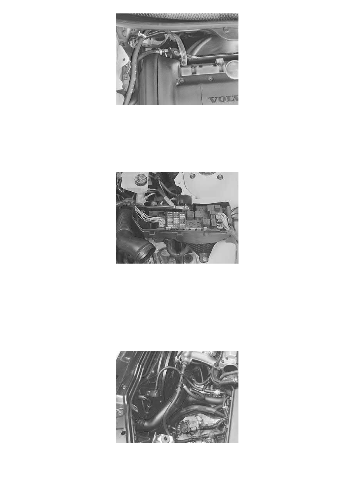
Installing the air conditioning (A/C) compressor
Install the 4 screws whilst the compressor is loose.
Raise the compressor and screw it into place.
Note! Handle the compressor carefully. Ensure that there are no kinks in the air conditioning (A/C) pipes.
Connect the one-pin connector to the compressor magnetic clutch.
Installing components
Connect the engine wiring to the control module box. See Central electrical unit, engine compartment, replacing See: Maintenance/Fuses and
Circuit Breakers/Fuse Block/Service and Repair/Central Electrical Unit Engine Compartment.
Install
- the ground lead to the ground terminal at the right fender edge in the engine compartment
- the auxiliaries belt
- the intermediate piece for the control module box
- the control modules. See Engine control module (ECM), replacing See: Powertrain Management/Computers and Control Systems/Engine
Control Module/Service and Repair
- the cover for the control module box
- expansion tank. Connect the radiator breather tube to the expansion tank. Tighten the clamp. Connect the connector for the level sensor in the
expansion tank
- servo oil reservoir. Check that the hoses are correctly positioned.
Clamp the ABS cable to the power steering hose.
Page 18
2005 Volvo XC70 L5-2.5L Turbo VIN 59 B5254T2 Copyright © 2011, ALLDATA 10.40 Page 5
gg
gggggggggggggggggggggg
Install
- the heat deflector plate above the turbocharger (TC)
- the 2 ground strips on the top of the cylinder head.
Clamp the wiring for the front heated oxygen sensor (HO2S) to
- the coolant pipe
- the heat deflector plate above the manifold
- the turbo control hose at the plastic intake pipe for the turbocharger (TC).
Install
- the positive lead for the starter motor
- the connector for the engine wiring
- the cover over the central electrical unit.
Installing the transmission cable
Automatic transmissions
Manual transmissions
Installing the engine coolant fan (FC)
: Install the screws holding the bracket and transmission cable to the transmission.
: Install the transmission cable. Assemble the clutch cable.
Install
- the lower engine coolant hose to the radiator. Tighten the clamp
- the lower oil cooler hose for the transmission to the radiator (automatic transmissions only). Use new O-rings
- the plastic charge air pipe between the throttle body (TB) and the charge air cooler (CAC). Only connect the plastic pipe at the throttle body
(TB). Do not tighten the clamp.
Page 19
2005 Volvo XC70 L5-2.5L Turbo VIN 59 B5254T2 Copyright © 2011, ALLDATA 10.40 Page 6
gg
gggggggggggggggggggggg
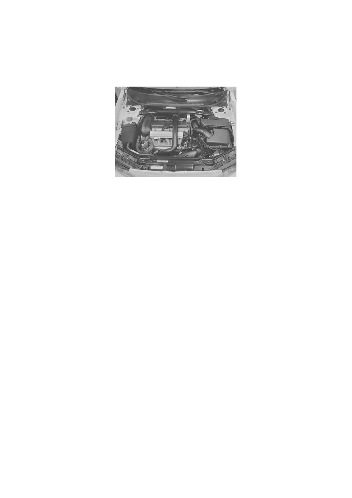
Remove radiator protection 999 5474
Install
- the engine cooling fan (FC). Tighten the screws securing the fan shroud to the front panel
- the plastic charge air pipe to the connection at the charge air cooler (CAC). Tighten both the clamps. Connect the connectors for the
temperature and pressure sensors in the plastic pipe
- the canister purge (CP) valve to the bracket at the fan shroud. Secure the EVAP hose to the clip at the lower section of the fan shroud
- the brake vacuum hoses
- the upper oil cooler hose for the transmission to the radiator (automatic transmissions only). Use new O-rings.
Press down the right side of the cooler unit. Pull the wiring for the pressure switch (Pressostat) into the drier bottle.
Connect the connectors to
- the engine cooling fan (FC) (x2)
- the canister purge (CP) valve.
Secure
- the breather tube for the radiator at the top of the fan shroud
- the wiring at the lower right corner and at the top of the fan shroud.
Install
- the rubber hose to the inlet side of the charge air cooler (CAC)
- the plastic charge air pipe above the engine. Tighten all clamps. Secure the pipe on the engine
- the upper coolant hose. Tighten the clamp
- the ventilation pipe between the control module box and fan shroud
- the air cleaner (ACL) assembly. Connect the plastic hose to the mass air flow (MAF) sensor. Tighten the clamp
- the air cleaner (ACL) intake pipe.
Connect the connector to the mass air flow (MAF) sensor. Secure the wiring at the front of the air cleaner (ACL) housing.
Install the support brace between the suspension turrets. Secure the servo hose to the right mounting on the support brace.
Finishing
Page 20
2005 Volvo XC70 L5-2.5L Turbo VIN 59 B5254T2 Copyright © 2011, ALLDATA 10.40 Page 7
gg
gggggggggggggggggggggg
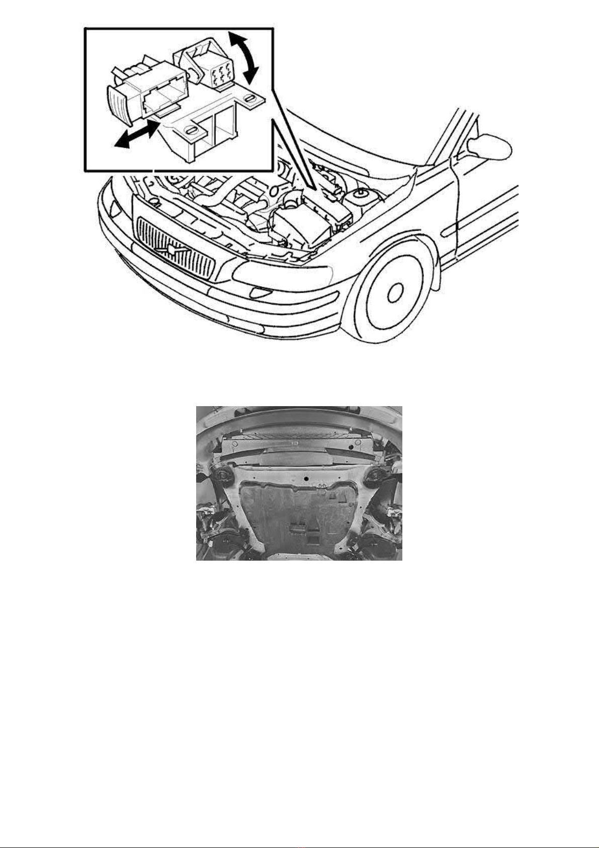
Connect the connector to the pressure switch (Pressostat) in the drier bottle. Secure the wiring.
Tighten the lower screw on the cooler unit.
Connect the connectors to both the heated oxygen sensors (HO2S).
Install
- the splash guard under the radiator
- the splash guard under the engine
- the front wheels. See Installing wheels See: Maintenance/Wheels and Tires/Wheels/Service and Repair
- the battery negative lead. Also read Battery, disconnecting See: Starting and Charging/Battery/Service and Repair/Procedures/Battery,
Disconnecting.
Final check
Top up
- coolant
- engine oil
- power steering fluid.
Start the engine.
Warm up the engine until the thermostat opens.
Check for leakage.
Check the oil and coolant levels. Adjust if necessary.
Check the transmission oil level (automatic transmissions only). Top up if necessary.
Engine/Transmission, Removing
Page 21
2005 Volvo XC70 L5-2.5L Turbo VIN 59 B5254T2 Copyright © 2011, ALLDATA 10.40 Page 8
gg
gggggggggggggggggggggg
Engine/transmission, removing
Special tools:
999 5474 RADIATOR PROTECTION See: Tools and Equipment/999 5474 Radiator Protection
999 5722 Wrench See: Tools and Equipment/999 5722 Wrench
Note! Since the illustrations in the information are used for different model years and/or models, there may be some deviations. However,
the essential information is always correct.
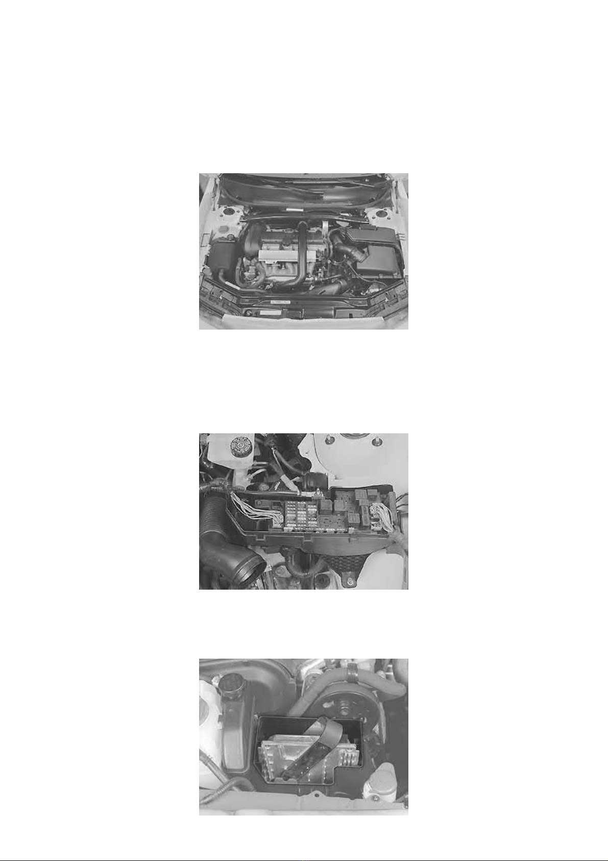
Preparation
Remove
- the negative battery cable. First read Battery, disconnecting See: Starting and Charging/Battery/Service and Repair/Procedures/Battery,
Disconnecting.
- the cross stay between the suspension turrets
- the air cleaner (ACL) assembly. Seal the opening in the plastic pipe for the turbocharger (TC)
- the plastic charge air pipe above the engine. Seal the openings
- both the ground strips at the top of the cylinder head.
Remove
- the cover over the central electrical unit
- the connector for the engine wiring from the central electrical unit
- the positive lead for the starter motor from the terminal block.
Page 22
2005 Volvo XC70 L5-2.5L Turbo VIN 59 B5254T2 Copyright © 2011, ALLDATA 10.40 Page 9
gg
gggggggggggggggggggggg
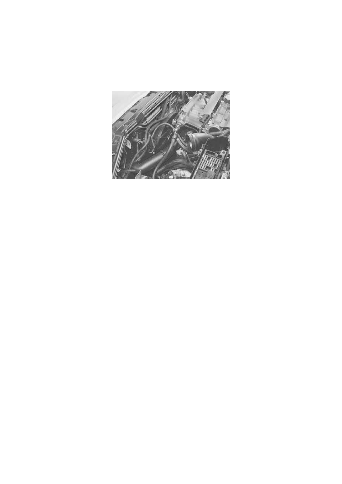
Remove
- control module unit cover
- the control modules. Use tool 999 5722 Wrench See: Tools and Equipment/999 5722 Wrench. See also Engine control module (ECM),
replacing See: Powertrain Management/Computers and Control Systems/Engine Control Module/Service and Repair.
Separate the control module box. Disconnect the engine wiring. Also see Central electrical unit, engine compartment, replacing See:
Maintenance/Fuses and Circuit Breakers/Fuse Block/Service and Repair/Central Electrical Unit Engine Compartment.
Remove the ground terminal for the engine wiring at the right wheel arch.
Removing the engine cooling fan (FC)
Remove
- the brake vacuum hose from the ejector valve
- The canister purge (CP) valve from the mounting on the fan shroud. Disconnect the connector.
Expose the wiring and the breather tube for the radiator.
Disconnect the connectors for the engine cooling fan (FC).
Remove
- the screws securing the fan shroud to the front panel
- the dip stick
- the upper oil hose for the transmission at the connection to the radiator (automatic transmissions only). Seal the openings.
Lift up and remove the engine cooling fan (FC).
Remove
- the connectors for the pressure sensor and temperature sensor in the plastic charge air pipe between the charge air cooler (CAC) and the
throttle body (TB)
- the rubber hose at the intake for the charge air cooler (CAC)
- the brake vacuum hose at the intake manifold
- the plastic pipe between the throttle body (TB) and the charge air cooler (CAC)
- the lower oil hose for the transmission at the connection to the radiator (automatic transmissions only). Seal the openings.
Install radiator protection 999 5474 RADIATOR PROTECTION See: Tools and Equipment/999 5474 Radiator Protection.
Removing the transmission cable
Automatic transmissions
Manual transmissions
Tie up the cable(s) to the central electrical unit.
Draining the fuel line
Drain the fuel line. See Fuel system pressure release See: Cylinder Head Assembly/Fuel Pressure Release/Service and Repair. See also: Fuel
system, quick-release connectors See: Powertrain Management/Fuel Delivery and Air Induction/Fuel Line Coupler/Description and Operation.
Remove the cover from the expansion tank.
Removing components
: Remove the screws for the transmission cable bracket at the transmission.
: Separate the clutch cable and remove the transmission cables.
Page 23
2005 Volvo XC70 L5-2.5L Turbo VIN 59 B5254T2 Copyright © 2011, ALLDATA 10.40 Page 10
gg
gggggggggggggggggggggg
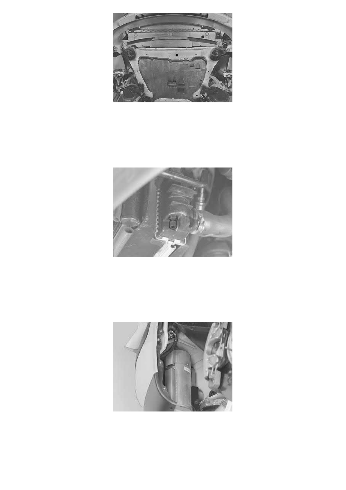
Raise the car.
Remove
- the left and right front wheels
- the splash guard under the radiator
- the splash guard under the engine.
Draining coolant
Position a container under the radiator drain cock.
Drain the coolant.
Warning! Avoid skin contact with the coolant.
Close the cock.
Cars with engine block heaters (option)
Drill out the first three blind rivets at the right mounting for the fender lining to the fender edge, seen from the front edge and upwards.
Bend the fender liner out of the way.
Disconnect the connector from the engine block heater.
Preparations for removal of the drive shafts
Page 24
2005 Volvo XC70 L5-2.5L Turbo VIN 59 B5254T2 Copyright © 2011, ALLDATA 10.40 Page 11
gg
gggggggggggggggggggggg
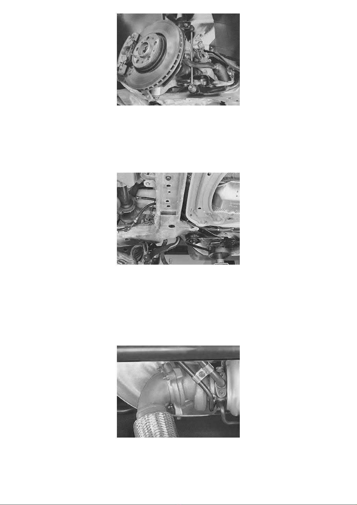
Remove on the left and right-hand sides
- the tie rod from the wheel spindle
- the link rod from the anti-roll bar
- the screw that holds the brake pipe bracket to the bodywork
- the nut holding the control arm to the ball joint
- the center screw from the end of the drive shaft.
Separating the fuel line
Note! If an engine block heater is installed, mark the position of the fuel lines.
Separate the quick-release connectors for the fuel pressure line and engine block heater (option). See also: Fuel system, quick-release connectors
See: Powertrain Management/Fuel Delivery and Air Induction/Fuel Line Coupler/Description and Operation.
Use tool 999 5666 Wrench See: Tools and Equipment/999 5666 Wrench.
Hint:
Pull apart the EVAP line at the rubber joint behind the rear right mounting for the sub-frame.
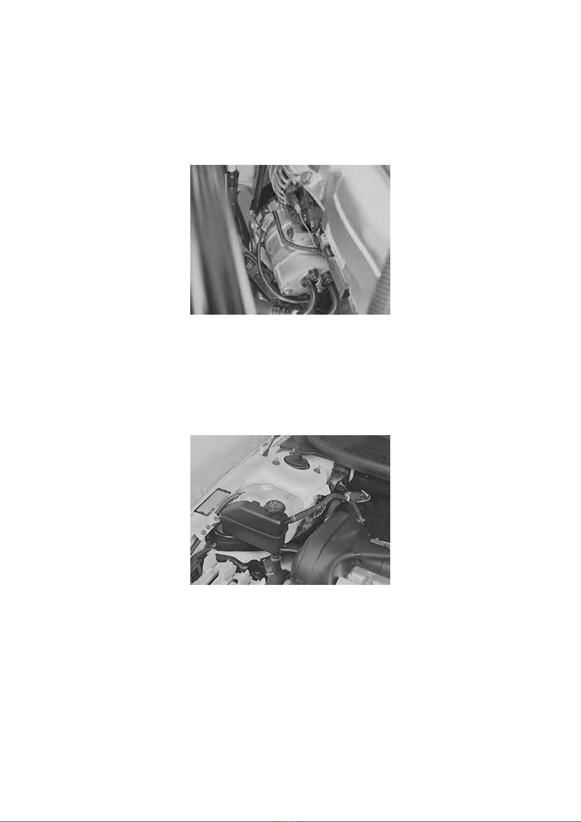
Separating the front exhaust pipe
Remove the screw from the wiring clamp that holds the wiring for the heated oxygen sensor (HO2S) at the right side of the steering gear.
Remove the wiring from the clips at the power steering line on the steering gear.
Remove
- the screw for the wiring clamp at the bracket at the rear edge of the sub-frame
- the lower screw that holds the heat deflector plate over the turbocharger (TC)
Page 25
2005 Volvo XC70 L5-2.5L Turbo VIN 59 B5254T2 Copyright © 2011, ALLDATA 10.40 Page 12
gg
gggggggggggggggggggggg
- the three nuts that hold the front exhaust pipe to the turbocharger (TC).
Tie up the front exhaust pipe at the right suspension turret (cars without All-wheel drive (AWD)).
Removing the air conditioning aggregate
Disconnect the connector from the pressostat in the air conditioning (A/C) receiver drier.
Slacken off the lower right screw for the cooling unit.
Pull the cooling unit down. Carefully pull the wiring for the pressostat through the cavity at the mounting for the cooling unit.
Release the lower ventilation pipe for the control module box from the sub-frame.
Exposing the air conditioning (A/C) compressor
Remove the upper radiator hose.
Remove the auxiliaries belt.
Disconnect the one-pin connector for the compressor magnetic clutch.
Remove the four screws holding the air conditioning (A/C) compressor to the engine.
Tie up the compressor in the front cover plate.
Note! Handle the compressor carefully to make sure that there is no bending of the AC-pipes.
Removing components
Expose the wiring for the front heated oxygen sensor (HO2S).
Disconnect the connector for the level sensor in the expansion tank.
Remove
- the heat deflector plate above the turbocharger (TC)
- the hoses for the heater unit at the terminal in the firewall
- the bleed hose for the radiator at the expansion tank
- the ABS line and clips and the power steering hose.
Lift up the power steering fluid reservoir and the expansion tank. Place them on top of engine.
Separating the steering shaft
Page 26
2005 Volvo XC70 L5-2.5L Turbo VIN 59 B5254T2 Copyright © 2011, ALLDATA 10.40 Page 13
gg
gggggggggggggggggggggg
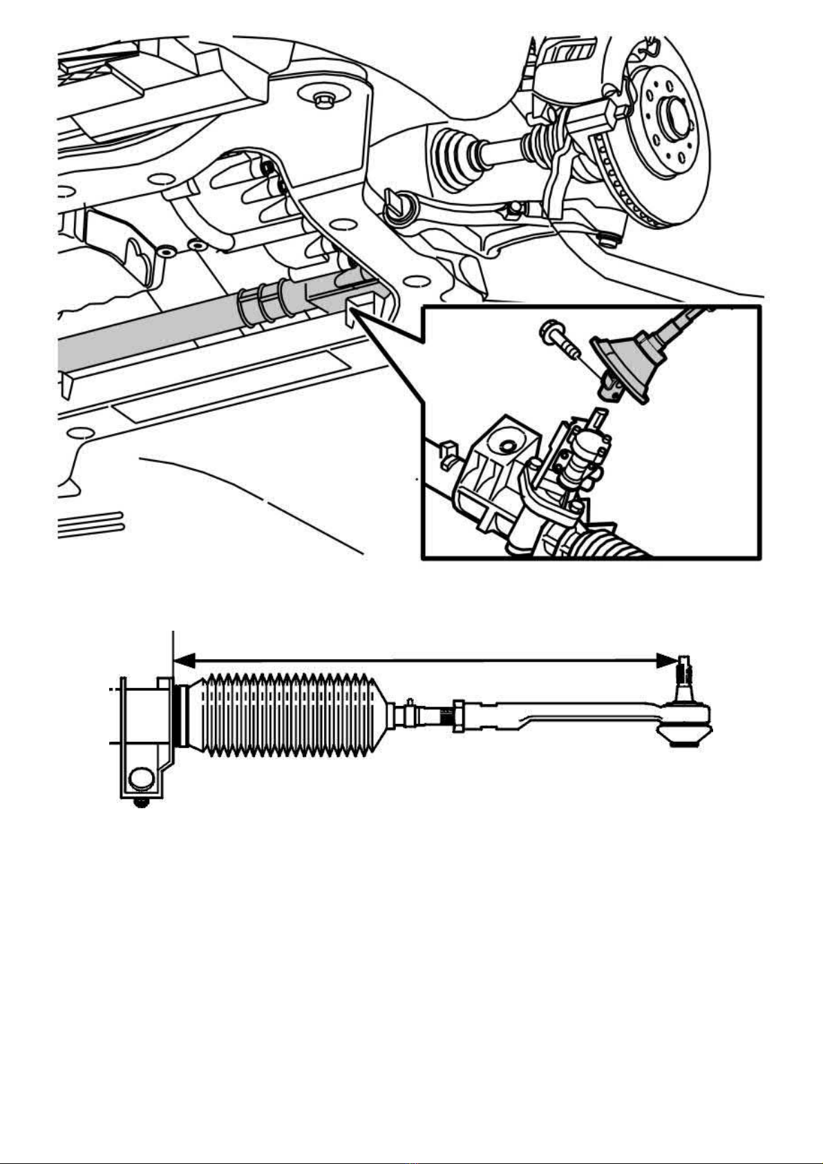
Remove the ignition key.
Remove the screw from the joint between the steering gear and the steering shaft.
On one side, measure the length of the track rod in relation to the steering gear housing. Note the measurement.
Press up the joint from the steering gear.
Caution! The steering shaft must not be turned. The contact reel in the SRS system could be damaged.
Removing the three-way catalytic converter (TWC) (all-wheel drive (AWD) only)
Remove
- the nuts where the exhaust pipe divides downstream of the three-way catalytic converter (TWC)
- the screws securing the SIPS member to the bodywork.
Remove the brake pipe from the holders on the SIPS member.
Lift off the front exhaust pipe from the turbocharger (TC) and the rear system.
Lower and pull back the three-way catalytic converter (TWC) with the SIPS member.
Note! The routing of the heated oxygen sensor's cable harness over brake pipe.
Removing the propeller shaft from the transmission and drive distribution box (all-wheel drive (AWD) only)
Page 27
2005 Volvo XC70 L5-2.5L Turbo VIN 59 B5254T2 Copyright © 2011, ALLDATA 10.40 Page 14
gg
gggggggggggggggggggggg
remove the propeller shaft from the transmission and drive distribution box (all-wheel drive (AWD) only). See Pinion seal bevel gear, replacing
See: Transmission and Drivetrain/Automatic Transmission/Transaxle/Seals and Gaskets/Service and Repair/Pinion Seal Bevel Gear, Replacing.
Lowering the engine and transmission
Use a post hoist with a lifting table and stud guides.
Position the lifting table against the sub-frame.
Note! Make sure that the lifting table is centered under the sub-frame for optimal weight distribution. Check that the lifting table is
correctly applied against the sub-frame.
Remove
- the sub-frame brackets screws
- the screws for the sub-frame.
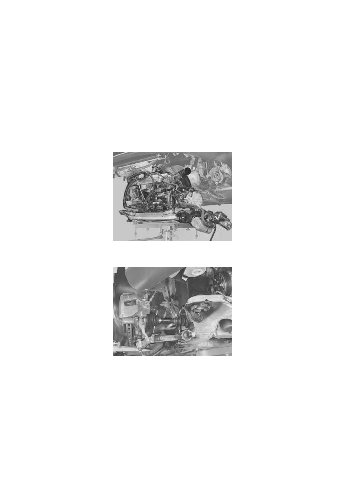
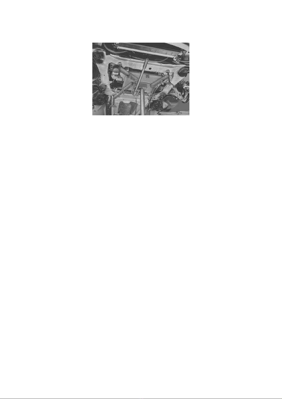
Lower the engine and transmission approximately 15 cm so that the drive shafts describe a horizontal line between the hub and transmission.
Caution! Make sure that no hoses, wiring or anything else catches when the engine/transmission unit is lowered.
Unhook the control arms from the ball joint pinion.
Hold the constant velocity joint. Pull the drive shaft off the hub. Let the drive shafts rest against the control arms.
Turn the engine block heater out of its position.
Check that the air conditioning (A/C) compressor is hanging free.
Continue lowering the engine and transmission unit.
Page 28
2005 Volvo XC70 L5-2.5L Turbo VIN 59 B5254T2 Copyright © 2011, ALLDATA 10.40 Page 1
gg
gggggggggggggggggggggg
Engine: Overhaul
Caulking
Caulking
Note! Some variation in the illustrations may occur, but the essential information is always correct.
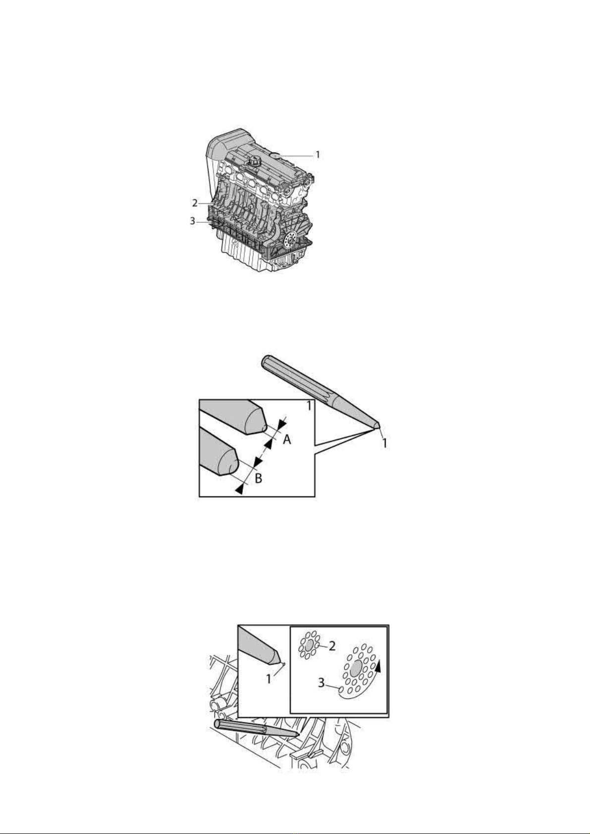
On engines manufactured of aluminium the camshaft bearing housing (1) cylinder block (2) and the intermediate section (3) may be caulked.
Note! The cylinder heads that are chill-cast may not be caulked.
Each individual case is assessed as to whether caulking can be carried out or not depending on the location of the oil leakage.
Caulking involves in the event of leakage knocking the material together using a special caulking tool.
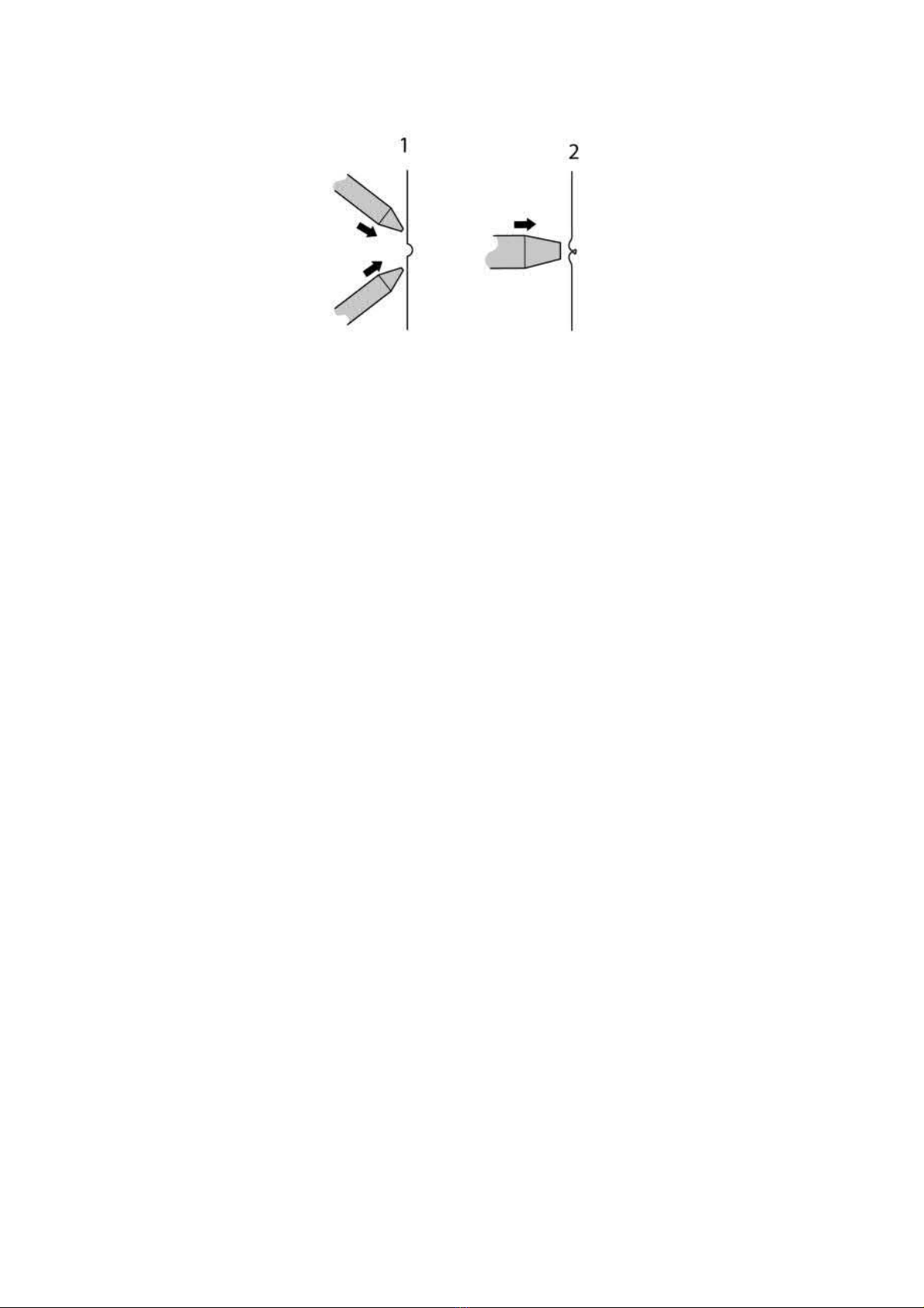
Two caulking tools are required. Use centre punches (1). Grind down the tips so they become round. One is to be ground so the rounded tip (A) is 2
mm. The other is ground so the rounded tip (B) is 4 mm.
Note! Use the protective goggles supplied with the leak tracing kit.
Isopropanol, 1161721
Use:
Use an UV light to localize the pore. Carefully wash round the pore with Isopropanol. Check with a UV light that all the oil has been removed.
Warning! Use protective goggles.
Page 29
2005 Volvo XC70 L5-2.5L Turbo VIN 59 B5254T2 Copyright © 2011, ALLDATA 10.40 Page 2
gg
gggggggggggggggggggggg
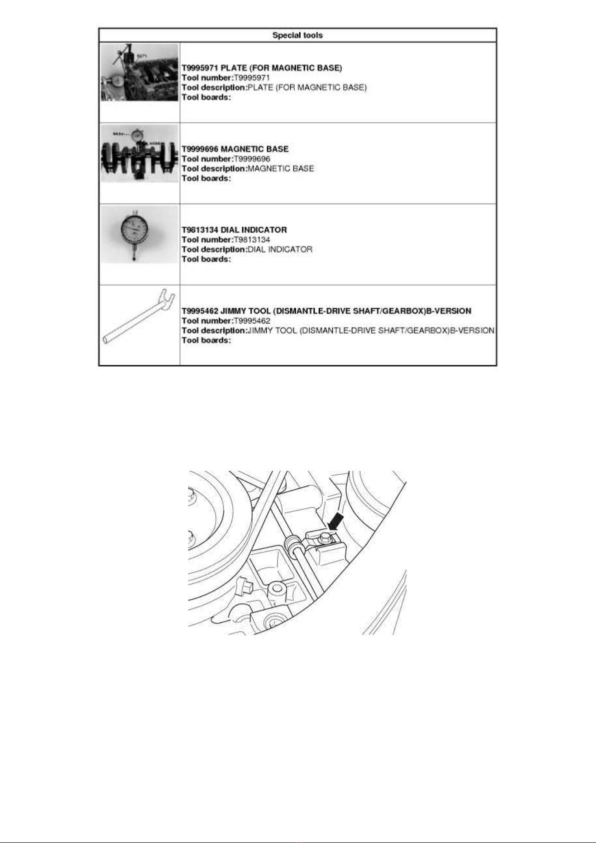
If the pore is small, it is sufficient to place the tool (2 mm) directly on the pore and hit it with a copper or plastic hammer. If the pore is larger, angle
the tool (2 mm) and drive the material in a circle toward the pore (2). If there is a lip around the pore, caulking (tool 4 mm) should be carried out in
a spiral form toward the pore (3).
Drive the material toward the pore (1) using the 2 mm tool. Seal using the 4 mm tool (2).
Isopropanol, 1161721
Use:
Wash with Isopropanol. Check with a UV lamp that there is no oil around the leakage point.
Test drive for 45 minutes as set out below to reach an oil temperature of about 80°C.
1. Allow the engine to idle for 20 minutes.
2. Test drive the car for 15 minutes.
3. Allow the engine to idle for a further 10 minutes.
Check using a UV light that the sealed area no long leaks. If leakage remains, repeat the caulking.
Crankshaft Axial Play
Crankshaft axial play
Operation number:
Note! Some variation in the illustrations may occur, but the essential information is always correct.
21685-2
Page 30
2005 Volvo XC70 L5-2.5L Turbo VIN 59 B5254T2 Copyright © 2011, ALLDATA 10.40 Page 3
gg
gggggggggggggggggggggg
Removal
Note! Removal steps in this procedure may contain installation details.
Remove the right front wheel.
When installing Refer to: Installing wheels See: Maintenance/Wheels and Tires/Wheels/Service and Repair
Fold away the wheel arch liner and tie it up.
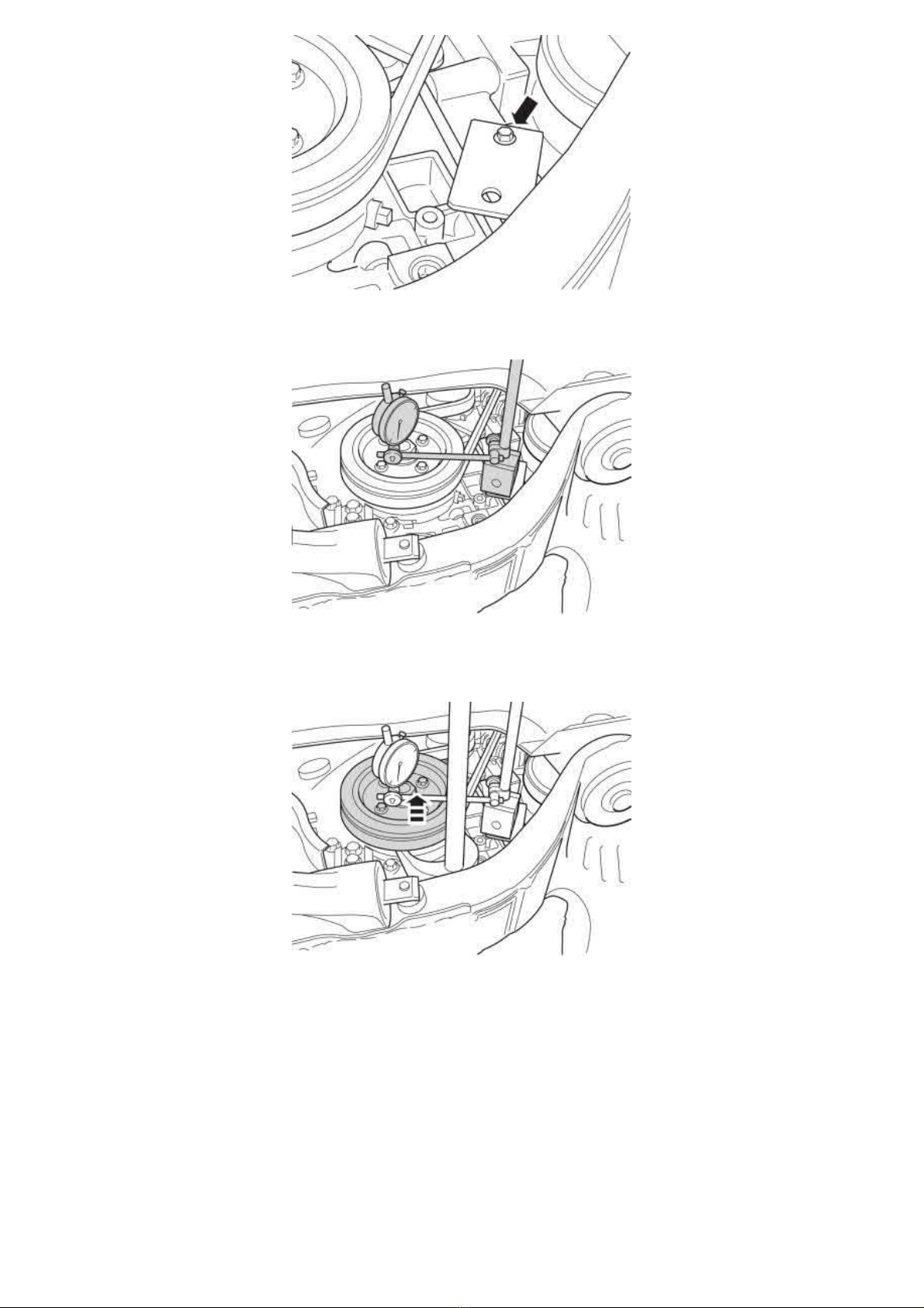
Remove the clamp screw on the fuel line. Move the clamp upward.
Torque:
M7, 17 Nm
Page 31
2005 Volvo XC70 L5-2.5L Turbo VIN 59 B5254T2 Copyright © 2011, ALLDATA 10.40 Page 4
gg
gggggggggggggggggggggg
999 5971 PLATE See: Tools and Equipment/999 5971 Plate
Torque:
M7, 17 Nm
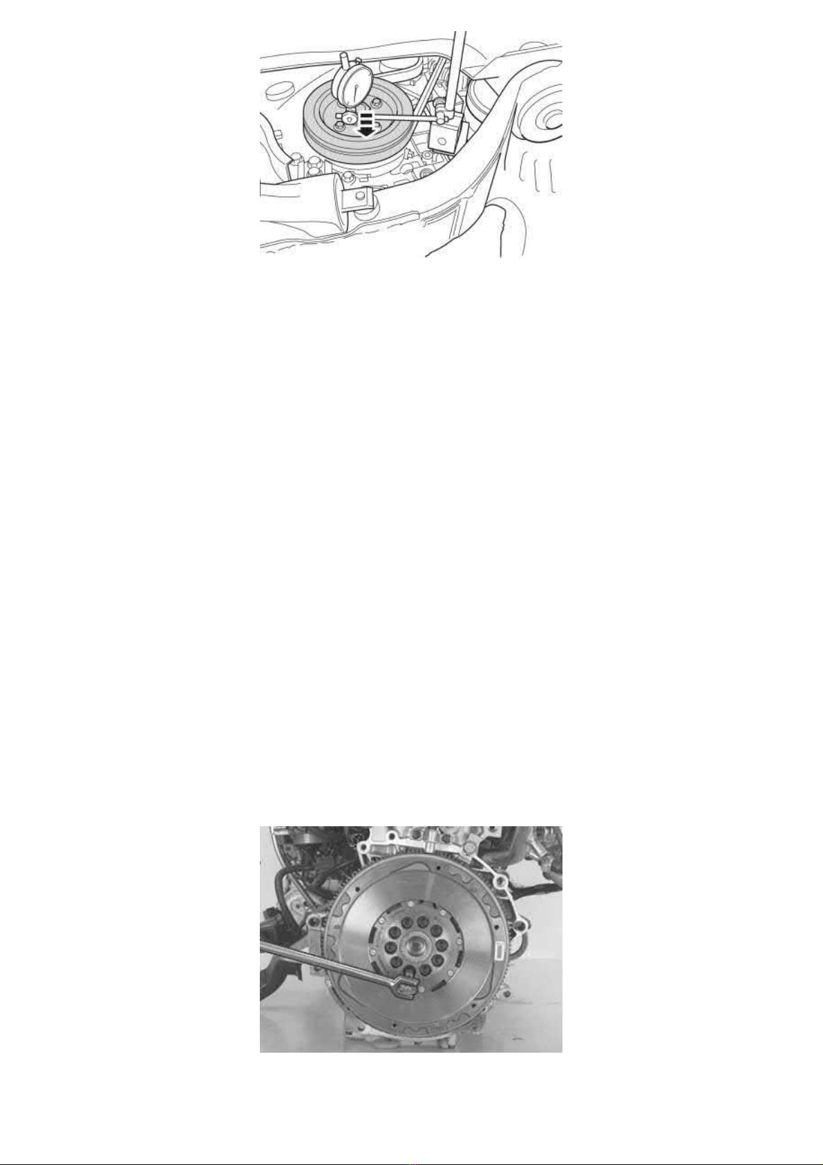
999 9696 MAGNETIC BASE See: Tools and Equipment/999 9696 Magnetic Base
981 3134 DIAL INDICATOR See: Tools and Equipment/981 3134 Dial Indicator
Measure the crankshaft nut or the oscillation damper's inner ring.
Pry out the crankshaft.999 5462 Jimmy tool See: Tools and Equipment/999 5462 Jimmy Tool
Zero the dial indicator.
Page 32
2005 Volvo XC70 L5-2.5L Turbo VIN 59 B5254T2 Copyright © 2011, ALLDATA 10.40 Page 5
gg
gggggggggggggggggggggg
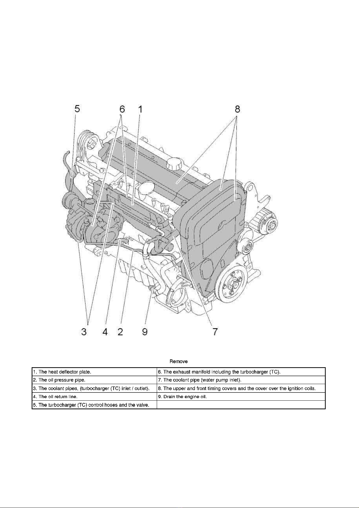
Push in the crankshaft. Use both hands and press hard. In the event of problems moving the crankshaft toward the gearbox, run the engine warm
and use a crowbar placed between the oscillation damper and the member. Use protective blocks.
Read the dial indicator. Max permitted play 0.25 mm.
Repeat the procedure several times.
Installation
Remove the test equipment.
To install, reverse the removal procedure
Engine Body, Exposing
Engine body, exposing
Special tools:
998 9721 SCREW SET See: Tools and Equipment/998 9721 Screw Set
999 2520 FLOOR STAND See: Tools and Equipment/999 2520 Floor Stand
999 5112 GEAR SECTOR See: Tools and Equipment/999 5112 Gear Sector
999 5297 ENGINE FIXTURE See: Tools and Equipment/999 5297 Engine Fixture
Note! As the illustrations in this service information are used for different model years and / or models, some variation may occur.
However, the essential information in the illustrations is always correct.
Removing the gearbox
Remove the lower screws (these are difficult to access) between the gearbox and engine before removing the engine and gearbox unit. The
Hint:
engine and gearbox unit must be placed on a suitable surface.
Relieve the transmission. Loose the remaining screws and remove the transmission
Remove the clutch.
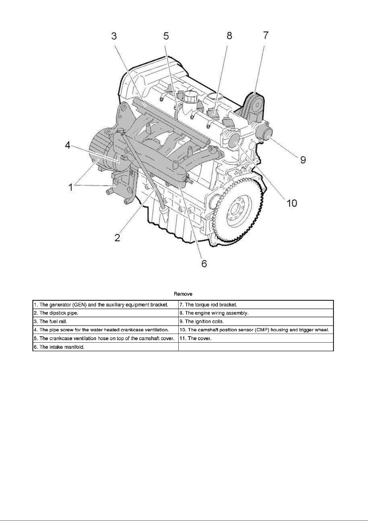
Removing the flywheel and carrier plate
carefully
.
Install gear sector 999 5112 GEAR SECTOR See: Tools and Equipment/999 5112 Gear Sector.
Remove all screws except for the uppermost screw which secures the flywheel to the crankshaft. Slacken off the uppermost screw. Leave it in
place, screwed in a few turns.
Page 33
2005 Volvo XC70 L5-2.5L Turbo VIN 59 B5254T2 Copyright © 2011, ALLDATA 10.40 Page 6
gg
gggggggggggggggggggggg
Carefully work the flywheel and carrier plate loose. If necessary, use 2 groove-cut chisels. Apply these between the cylinder block and the flywheel
and carrier plate.
Hold the flywheel and carrier plate and remove the final screw.
Install the engine in a stand
Use mounting stand 999 2520 FLOOR STAND See: Tools and Equipment/999 2520 Floor Stand , fixture 999 5297 ENGINE FIXTURE See:
Tools and Equipment/999 5297 Engine Fixture and screw set 998 9721 SCREW SET See: Tools and Equipment/998 9721 Screw Set.
Exposing the engine
Page 34
2005 Volvo XC70 L5-2.5L Turbo VIN 59 B5254T2 Copyright © 2011, ALLDATA 10.40 Page 7
gg
gggggggggggggggggggggg
Engine Block, Installing Components
Engine block, installing components
Note! As the illustrations in this service information are used for different model years and / or models, some variation may occur.
However, the essential information in the illustrations is always correct.
Installing engine block components
Note! Always use new seal washers and gaskets!
Install
- thermostat housing (B52x4x)
- knock sensor (KS)
- flame trap
- the pipe screw for the water-heated crankcase ventilation.
B5xx4x
B6xx4x
Install the flywheel and carrier plate. See Crankshaft seal rear, replacing See: Seals and Gaskets/Crankshaft Main Bearing Seal/Service and Repair.
. Engine body, exposing, B5254T2 See: Engine Body, Exposing
. Engine body, exposing, B5254T2 See: Engine Body, Exposing
Page 35
2005 Volvo XC70 L5-2.5L Turbo VIN 59 B5254T2 Copyright © 2011, ALLDATA 10.40 Page 8
gg
gggggggggggggggggggggg
B5xx4x
B6xx4x
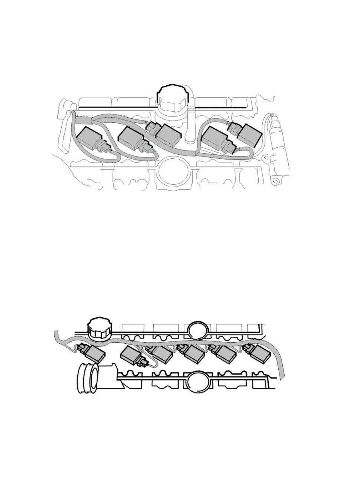
The ignition coil alignment and the wiring routing follows the illustrations below.
B5xx4x
. Tightening torque See: Specifications/Tightening Torque
. Tightening torque See: Specifications/Tightening Torque
B6xx4x
Sealing Micro-Enclosed Screws
Page 36
2005 Volvo XC70 L5-2.5L Turbo VIN 59 B5254T2 Copyright © 2011, ALLDATA 10.40 Page 9
gg
gggggggggggggggggggggg
Sealing micro-enclosed screws
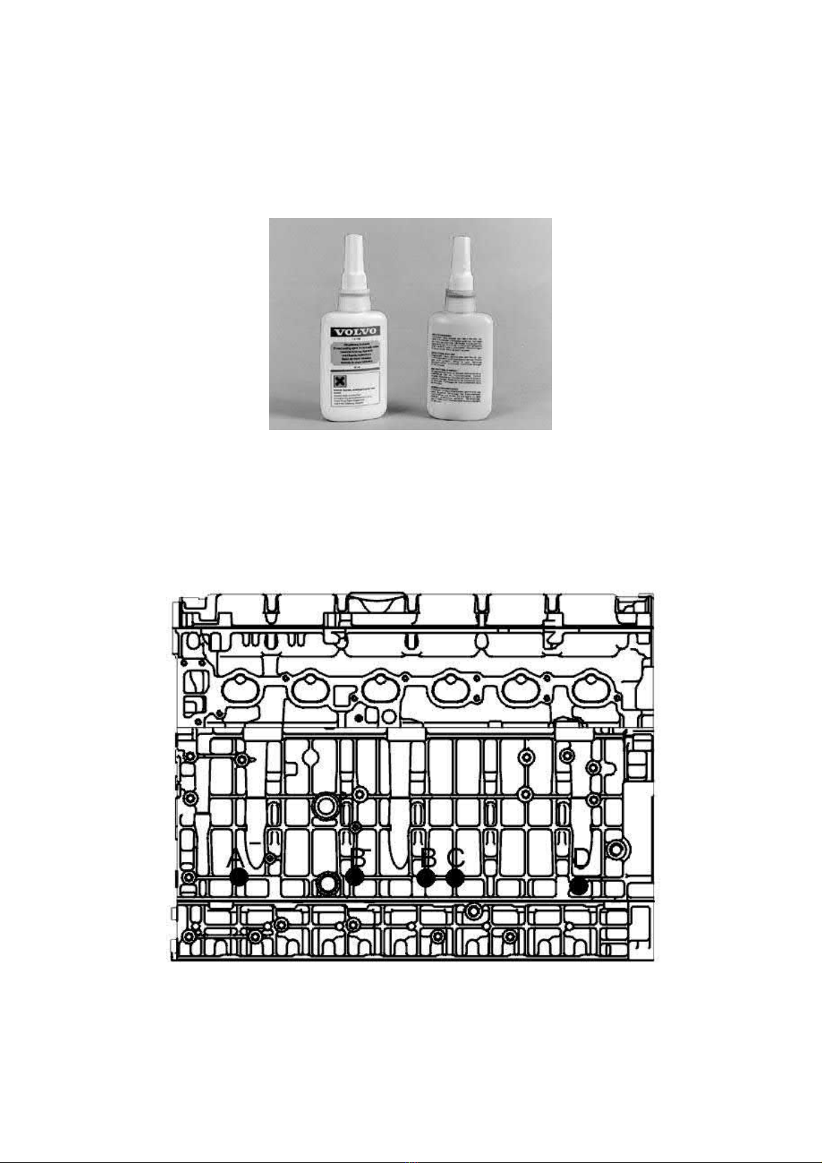
Note! Micro-enclosed screws are used where the seal requirements are high. Loose screws are replaced or sealed with new sealing
compound. Sealant "HYDRAULIC THREADSEAL" has P/N 11 61 056-5 and sealing must be carried out according to the instructions on
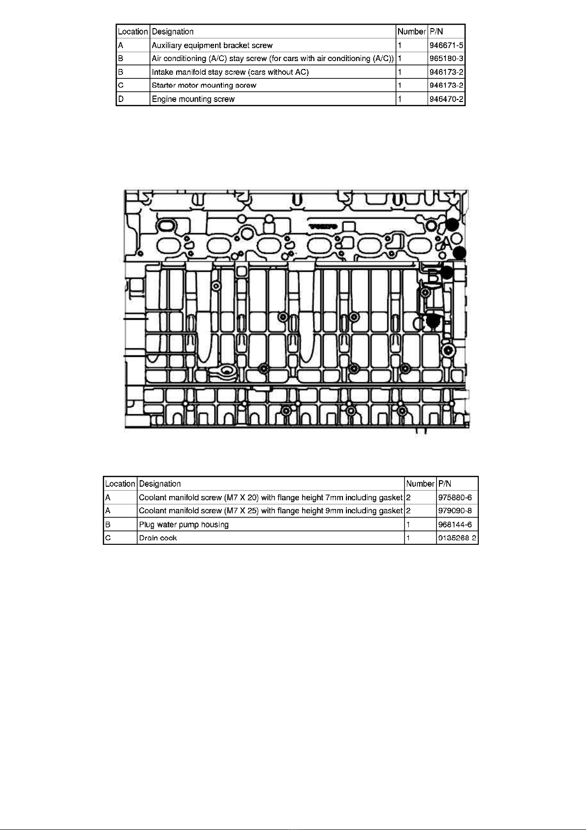
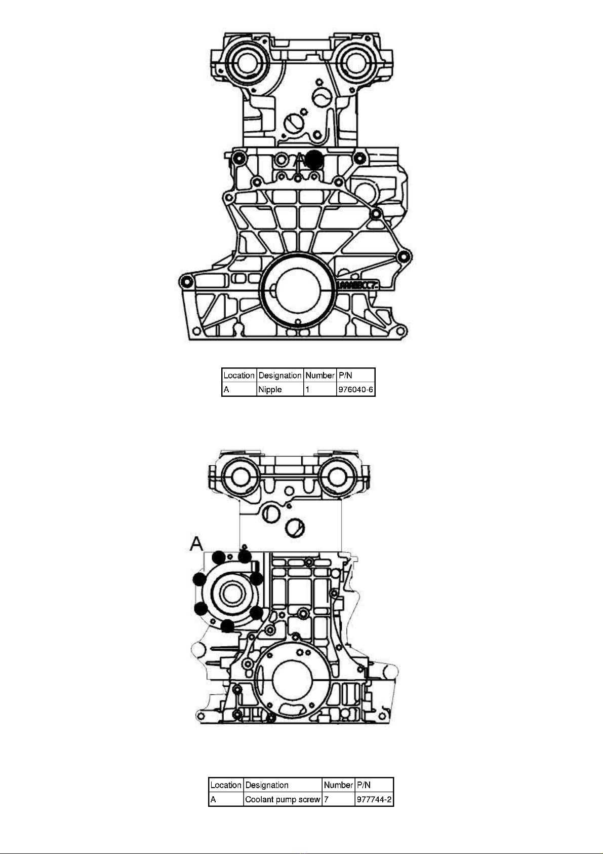
the packet.The screws to be sealed with "HYDRAULIC THREAD SEAL" and their positions are shown below.
Note! As the illustrations in this service information are used for different model years and / or models, some variation may occur.
However, the essential information in the illustrations is always correct.
Sealant
"Hydraulic thread sealant"
- P/N 11 61 056-5
- Use a brush and/or the packet spout to apply the sealant to the screw.
- Avoid skin contact with the sealant.
Engine intake side
Page 37
2005 Volvo XC70 L5-2.5L Turbo VIN 59 B5254T2 Copyright © 2011, ALLDATA 10.40 Page 10
gg
gggggggggggggggggggggg
Engine exhaust side
Rear of engine
Page 38
2005 Volvo XC70 L5-2.5L Turbo VIN 59 B5254T2 Copyright © 2011, ALLDATA 10.40 Page 11
gg
gggggggggggggggggggggg
Engine front
Page 39
2005 Volvo XC70 L5-2.5L Turbo VIN 59 B5254T2 Copyright © 2011, ALLDATA 10.40 Page 12
gg
gggggggggggggggggggggg
Threads
Threads
Note! As the illustrations in this service information are used for different model years and / or models, some variation may occur.
However, the essential information in the illustrations is always correct.
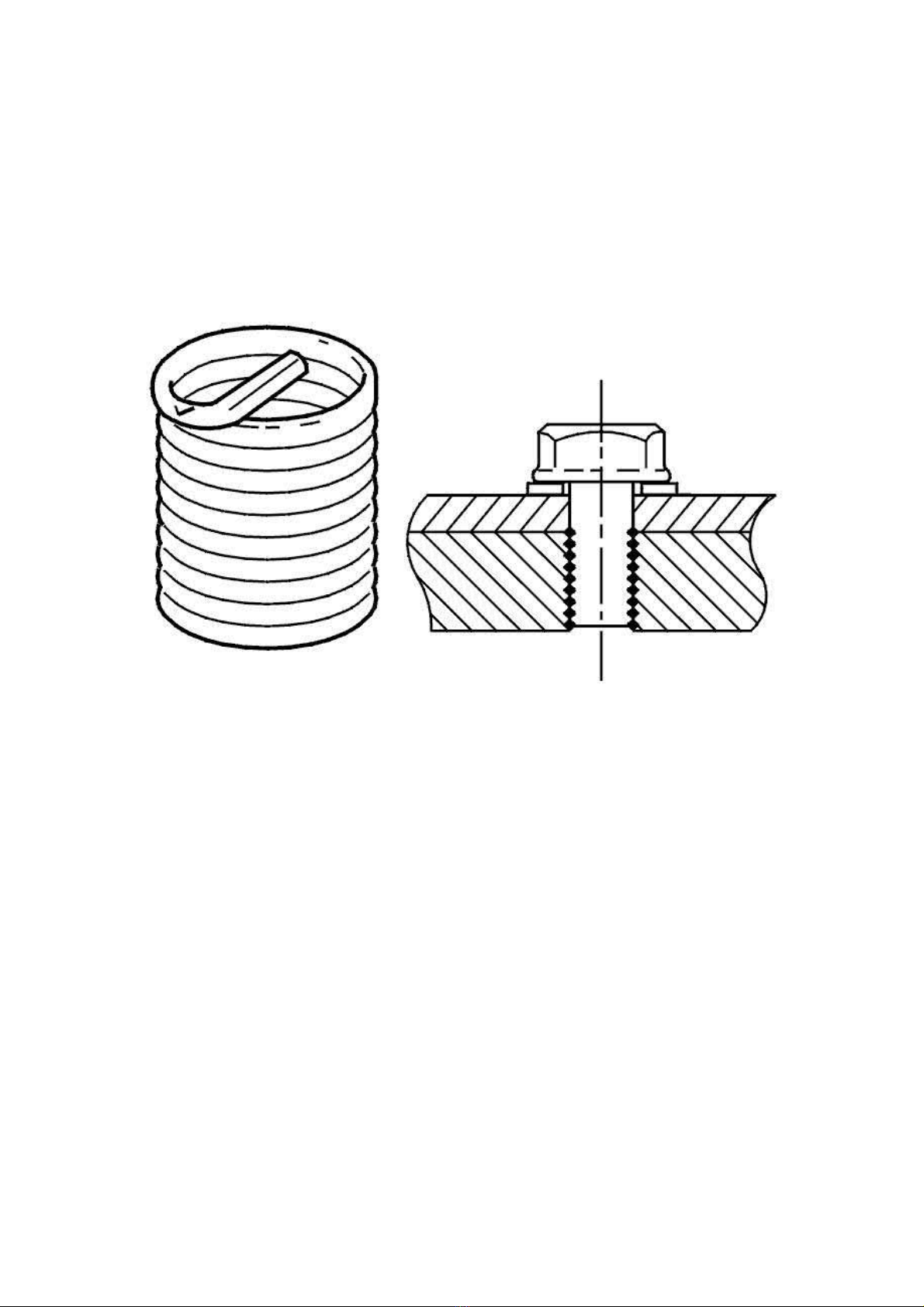
Thread inserts, general
Damaged threads can in most cases be reconditioned using HELICOIL thread inserts.
Thread inserts are available in a variety of sizes, pitches and lengths. A correctly reconditioned thread will generally increase the strength of a joint.
Designation of thread insert
Page 40
2005 Volvo XC70 L5-2.5L Turbo VIN 59 B5254T2 Copyright © 2011, ALLDATA 10.40 Page 13
gg
gggggggggggggggggggggg
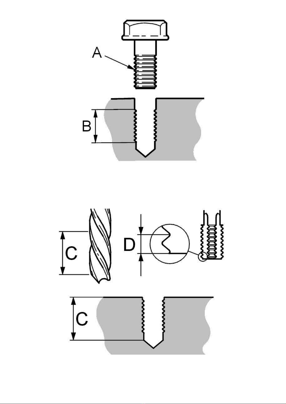
Measure the old threads and thread length in the hole.
Thread.
A:
Thread length.
B:
Drilling and tapping new thread in the hole
Drill out the old threads using the correct diameter drill bit. Blow the hole clean.
Tap the new thread using the correct tap.
Note! The thread taps referred to in the text are specially made for use with the HELI-COIL system.
Page 41
2005 Volvo XC70 L5-2.5L Turbo VIN 59 B5254T2 Copyright © 2011, ALLDATA 10.40 Page 14
gg
gggggggggggggggggggggg
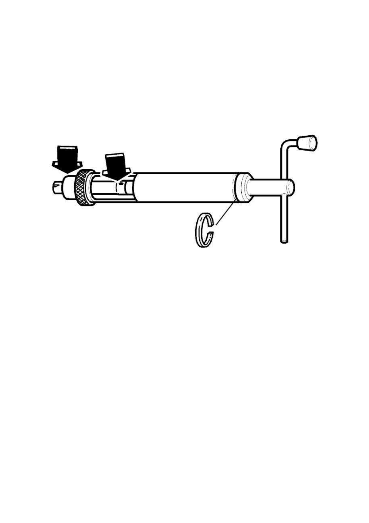
Use methylated spirit or similar to lubricate the threading operation in aluminium. Thread longer threads in stages, backing out the tap and blowing
the tap and the hole clean in between.
Thread the hole to the proper depth (or through if it is to be threaded throughout).
C: drill depth.
D: cutting phase.
Tools required for installation
The installation tool (illustrated) is used for threads
ring, for example with countersunk threads.
For threads
Installing the thread insert in the installation tool
and larger the specific tool for each thread size must be used The guide and mandrel are included.
M16
M6 - M14
. During some operations the tool must be disassembled by removing the locking
Page 42
2005 Volvo XC70 L5-2.5L Turbo VIN 59 B5254T2 Copyright © 2011, ALLDATA 10.40 Page 15
gg
gggggggggggggggggggggg
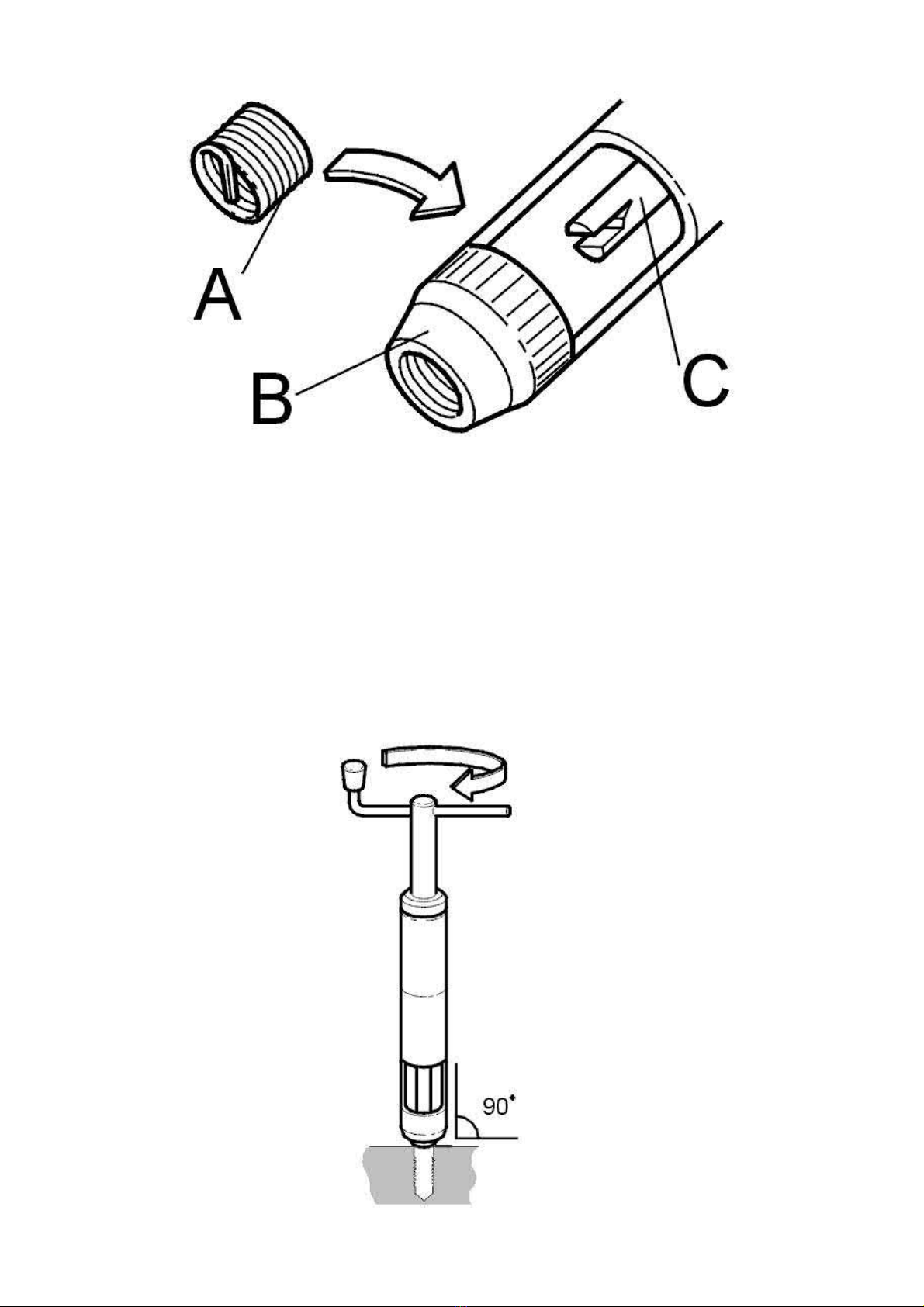
Locate the thread insert with the tang facing down in the tool.
Turn the spindle until the tang engages in the recess.
Screw the thread insert into the guide, do not apply pressure, until the first turn of the thread insert is flush with the guide opening.
A: Tang.
B: Guide.
C: Mandrel.
Installation of thread insert
Hold the installation tool straight above and centered over the hole. Screw in the insert without applying pressure on the spindle handle. Screw in
Page 43
2005 Volvo XC70 L5-2.5L Turbo VIN 59 B5254T2 Copyright © 2011, ALLDATA 10.40 Page 16
gg
gggggggggggggggggggggg
until the end of the insert reaches at least half a thread revolution into the thread.
The insert must not touch the bottom of the hole or stick out of the other side if it is a through hole.
Break off the tang with the proper tang breaker. For
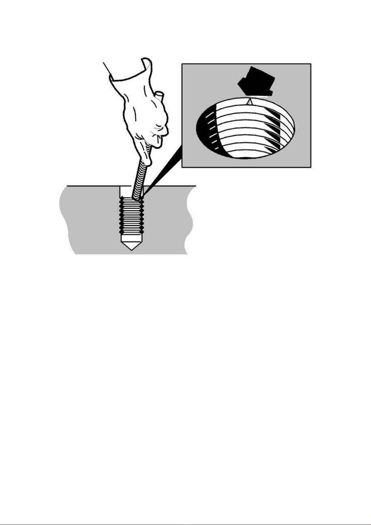
Extraction of damaged thread insert
threads and coarser, use a pair of flat-nosed pliers or similar and break downwards.
M14
Alternative 1
File a notch in the thread insert, about a quarter turn in from the end. Do not file through the insert.
Note! Do not damage the thread in the material.
Use a triangular scraper or similar to extract the insert by rotating it.
Alternative 2
Carefully expose the end of the thread insert. Use flat-nose pliers to pull the thread insert out.
Clean out the threads in the hole using the thread tap and blow clean.
Install a new thread insert.
Reconditioning sparkplug threads
Note! Reconditioning of spark plug threads must be carried out with removed cylinder head.
Tapping thread in sparkplug hole
Page 44
2005 Volvo XC70 L5-2.5L Turbo VIN 59 B5254T2 Copyright © 2011, ALLDATA 10.40 Page 17
gg
gggggggggggggggggggggg
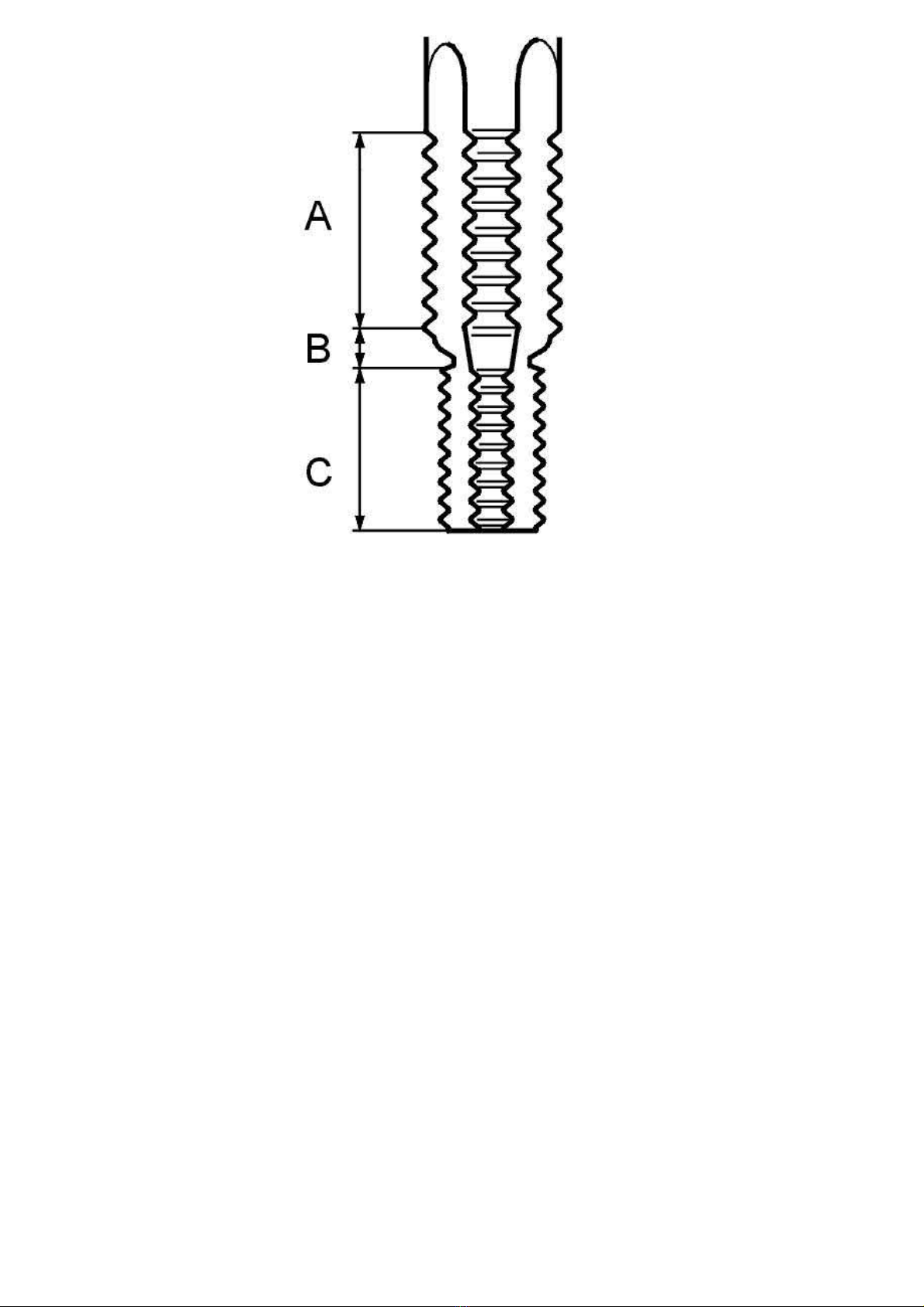
Use combination tap 998 5823-5 and thread repair inserts for spark plug thread
Note! Do not drill out spark plug threads.
Combined tap
Tap.
A:
Reamer.
B:
Steering.
C:
Installation of thread insert
M14x1,25
.
Page 45
2005 Volvo XC70 L5-2.5L Turbo VIN 59 B5254T2 Copyright © 2011, ALLDATA 10.40 Page 18
gg
gggggggggggggggggggggg
There are times when the cap nut cannot be used because of space restrictions. On these occasions the guide should be taped into place.
Note! As the thread insert for the spark plug thread is thinner (finer) than usual it is extra important to not pressure on the pin when
inserting the thread insert (both in the nozzle and the material).
Twist the thread insert down and check that the upper thread is at least a half thread down into the thread and that none of the insert protrudes into
the combustion chamber.
If the insert has been screwed in too far it must be turned until it is all the way through. If it is not deformed it can be inserted again.
Break off the tang with a pair of flat nose pliers. Check the thread. Install a sparkplug.
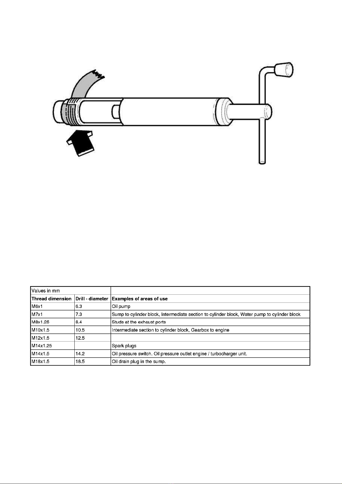
Thread table
Threads which must not be reconditioned
Coolant outlet for the drain nipple, heat exchanger / oil cooler.
Plug hole for crankshaft setting.
Screw holes for cylinder head screws.
Page 46
2005 Volvo XC70 L5-2.5L Turbo VIN 59 B5254T2 Copyright © 2011, ALLDATA 10.40 Page 1
gg
gggggggggggggggggggggg
Variable Valve Timing Actuator: Description and Operation
Camshaft Control (CVVT)
Camshaft Control (CVVT)
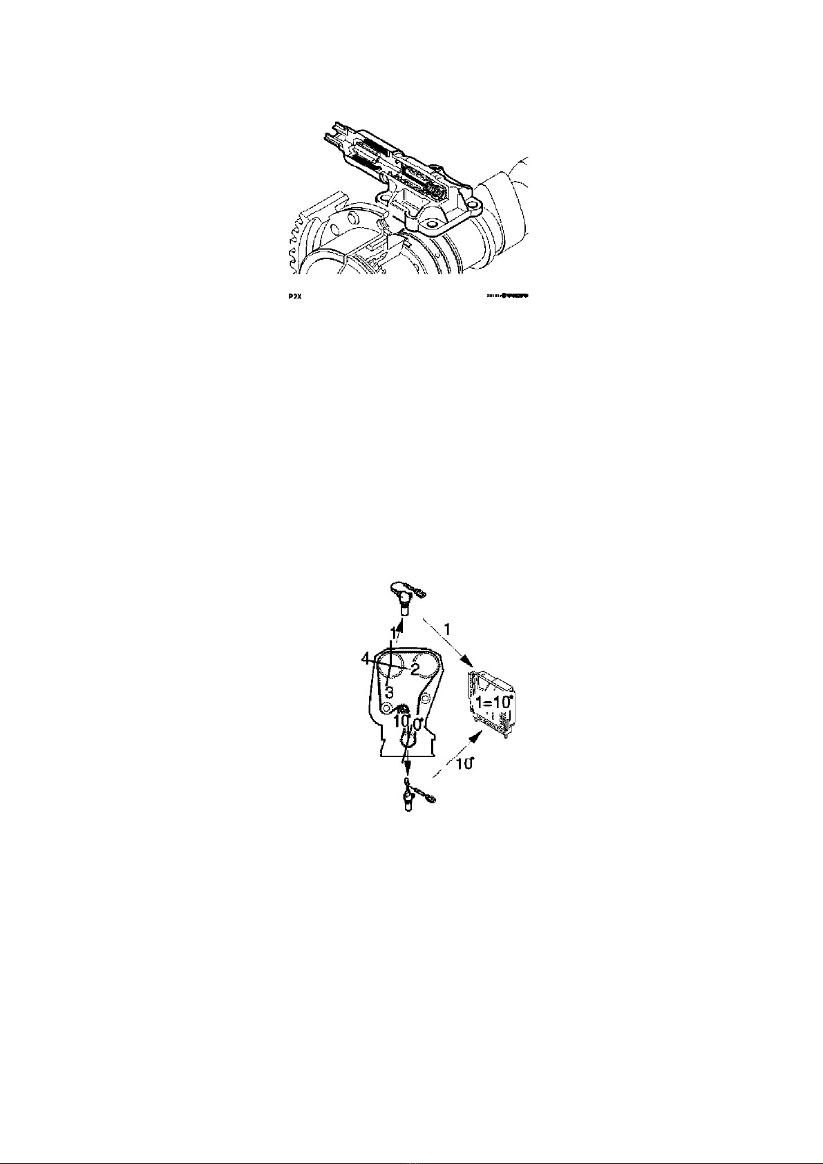
When the camshaft is set at the factory, it is aligned with the position of the crankshaft. The position of the camshaft in relation to the crankshaft is
designated the camshaft 0 position.
During camshaft control (CVVT) the camshaft 0 position is offset. The value of the 0 position offset is called the cam timing. The cam timing is 0
degrees if the camshaft is not being controlled.
By controlling the cam timing (the camshaft is deployed from its 0 position) the performance of the engine is increased, the idle speed quality is
improved and the emissions are reduced.
In order to detect the cam timing, the engine control module (ECM) uses the signals from the engine speed (RPM) sensor (the position of the
crankshaft) and from the camshaft position (CMP) sensor (the position of the camshaft). By comparing these two signals, the control module is able
to determine the cam timing (the number of degrees the camshaft is from its 0 position).
There are diagnostic for this function. See also Camshaft diagnostics (CVVT).
Camshaft cam timing
The camshaft (A) is divided into four flanks per revolution of the camshaft (flanks 1-4). The angle between flanks 1-2 = 103 degrees, flanks 2-3 =
90 degrees, flanks 3-4 = 90 degrees and flanks 4-1 = 77 degrees. The angle between the flanks is different, allowing the control module to
determine which flank it is detecting and therefore determine which combustion cycle the cylinders are in.
The crankshaft has four reference positions, one for each camshaft flank. The camshaft turns at half the speed of the crankshaft. This means that
two reference positions are detected for each turn of the crankshaft. Therefore two engine revolutions are required to detect all flanks on the
camshaft. For example (may vary between different engine variants): flank 1 at 0 degrees, flank 2 at 206 degrees, flank 3 at 386 degrees and flank 4
at 576 degrees (flanks 3 and 4 are detected during the second engine revolution).
The reference positions of the crankshaft coincide exactly with each camshaft flank if the camshaft cam timing is 0 degrees. If the cam timing
deviates from 0 degrees, i.e. the flanks deviate from the reference positions of the crankshaft, the control module calculates the number of
crankshaft degrees by which the flank is deviating.
The control module detects the reference positions for the camshaft flanks using the signal from the engine speed (RPM) sensor.
Example:
If camshaft flank 1 is detected at 10 degrees from the crankshaft reference position for flank 1 (0 degrees +10 degrees), the cam timing is 10
degrees. If the cam timing is the same (10 degrees), flank 2 is detected at 216 degrees (206 degrees + 10 degrees), flank 3 at 396 degrees (386
degrees + 10 degrees), and flank 4 at 586 degrees (576 degrees + 10 degrees). The cam timing can be positive (+) or negative (-) depending on
Page 47
2005 Volvo XC70 L5-2.5L Turbo VIN 59 B5254T2 Copyright © 2011, ALLDATA 10.40 Page 2
gg
gggggggggggggggggggggg
whether the flank is detected before or after the different reference positions for the crankshaft.
The engine control module (ECM) controls the camshaft reset valve smoothly in order to regulate the camshaft cam timing. The valve controls the
flow of engine oil to the continuous variable valve timing (CVVT) unit which is affected by the oil pressure that builds up. Also see Design.
Control
Control takes place as follows when deploying the camshaft:
Control takes place as follows when returning the camshaft:
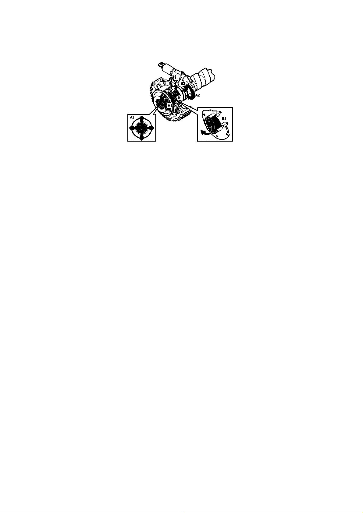
1. Oil is forced from the engine lubricating system to the intake port on the reset valve
2. The engine control module (ECM) grounds the valve, the position of the piston in the valve changes and the oil is guided to the continuous
variable valve timing (CVVT) unit chamber (A1) via the duct (A2) in the camshaft
3. The continuous variable valve timing (CVVT) unit hub is pressed backwards by the oil pressure. The continuous variable valve timing
(CVVT) unit then rotates the hub and the carriers are joined by twisted splines
4. The oil flows to the engine oil pan via the outer ducts on the hub and the reset valve's return hose.
1. Oil is forced from the engine lubricating system to the intake port on the reset valve
2. The engine control module (ECM) breaks the ground connection for the valve. The piston in the valve is then pressed back by a spring. The
oil flows to the continuous variable valve timing (CVVT) unit chamber (B1) via a duct (B2) in the camshaft
3. The hub of the continuous variable valve timing (CVVT) unit is forced forward by the oil pressure that is created. The continuous variable
valve timing (CVVT) unit will rotate back to the nondeployed position
4. The oil flows to the engine oil pan via the center duct on the hub and the reset valve's return duct.
The above takes place very quickly. The engine control module (ECM) controls the deployment and return of the reset valve continually at high
frequency. This results in rapid and exact control.
The extent of camshaft control (the change of cam timing) varies depending on the engine variant and the model year.
Page 48

2005 Volvo XC70 L5-2.5L Turbo VIN 59 B5254T2 Copyright © 2011, ALLDATA 10.40 Page 1
gg
gggggggggggggggggggggg
Variable Valve Timing Actuator: Description and Operation
Knock Control
Knock Control
Knocking occurs in the combustion chamber when the fuel and air mixture self ignites. This can occur either before or after the spark plug has
produced an ignition spark. In both cases the gas in two or more places ignites in the combustion chamber.
This results in an extremely fast combustion process with flames from several directions. When these flames collide, the pressure in the cylinder
increases rapidly and there is a mechanical knocking sound.
If any of the cylinders knock there is a specific type of vibration in the cylinder block. These vibrations are transferred to the knock sensors (KS)
which are screwed into place in the cylinder block. The resultant mechanical stress in the piezo electrical material in the knock sensors generates a
voltage. The engine control module (ECM) can then determine which cylinder is knocking with the help of the camshaft position (CMP) sensor and
the engine speed (RPM) sensor.
The knock sensors (KS) also interpret a proportion of normal engine sound. The control module is able to recognize the vibrations which
correspond to knocking by filtering, amplifying and using software to evaluate the signal.
If the knock sensors (KS) detect knocking in the engine over a certain threshold value, the
mixture is enriched to eliminate knocking.
ignition timing is first retarded and then the fuel / air
Page 49
2005 Volvo XC70 L5-2.5L Turbo VIN 59 B5254T2 Copyright © 2011, ALLDATA 10.40 Page 1
gg
gggggggggggggggggggggg
Variable Valve Timing Actuator: Description and Operation
Camshaft Reset Valve
Camshaft Reset Valve (Continuous Variable Valve Timing (CVVT))
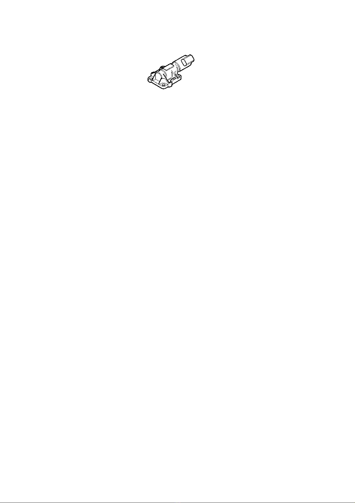
The camshaft reset valve controls the oil flow to the CVVT unit (camshaft pulley).
The valve consists of an electro-magnetic valve with a spring-loaded piston. There are slits in the piston which channel the engine lubricating oil to
the CVVT unit by moving the piston in the reset valve. The continuous variable valve timing (CVVT) unit turns the camshaft (the cam timing
changes). The direction in which the camshaft turns depends on the chamber in the CVVT unit which is supplied with oil (pressure). Also see
Function.
The system relay supplies the reset valve with voltage. The valve is grounded (control stage) in the engine control module (ECM). When the valve
is grounded using a pulse width modulation (PWM) signal, the oil flow in the valve can be controlled to the different chambers in the continuous
variable valve timing (CVVT) unit at variable rates. This allows the cam timing to be changed precisely and steplessly.
The engine control module (ECM) can diagnose the camshaft reset valve.
The valve is on the cylinder head above the camshaft with camshaft control.
Page 50
2005 Volvo XC70 L5-2.5L Turbo VIN 59 B5254T2 Copyright © 2011, ALLDATA 10.40 Page 1
gg
gggggggggggggggggggggg
Variable Valve Timing Actuator: Description and Operation
Variable Valve Timing Control
Variable valve timing control
Continuous variable valve timing (CVVT) control, general
The engine combustion can be improved by changing the shift angle of the camshaft. This reduces emissions, gives lower fuel consumption and
better performance. The shift angle of the camshaft is controlled by the control module which changes the pulse ratio of the reset valve. The pulse
ratio of the reset valve affects the variable valve timing unit which changes the camshaft position compared to the
ensures quick and precise control of the shift angle of the camshaft.
°
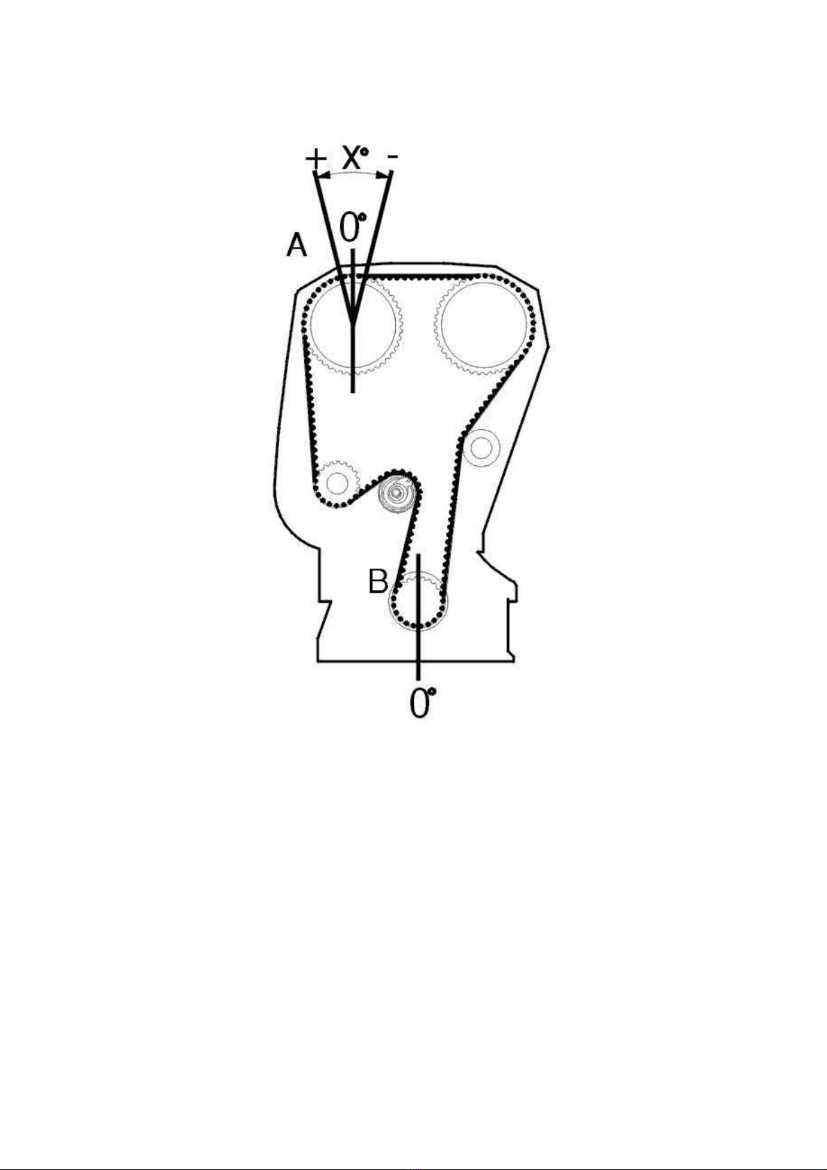
Definition of "Camshaft shift angle" (X)
When the camshaft (A) is set at the factory it is aligned to top dead center (TDC) on the crankshaft which is 0° (B). The camshaft position when
aligned to the crankshaft TDC is the camshaft 0 position (0°). With continuous variable valve timing (CVVT) the camshaft 0 position is offset, the
value of the offset of the camshaft 0 position is the camshaft shift angle (x°).
crankshaft position (CKP). This
Page 51
2005 Volvo XC70 L5-2.5L Turbo VIN 59 B5254T2 Copyright © 2011, ALLDATA 10.40 Page 2
gg
gggggggggggggggggggggg
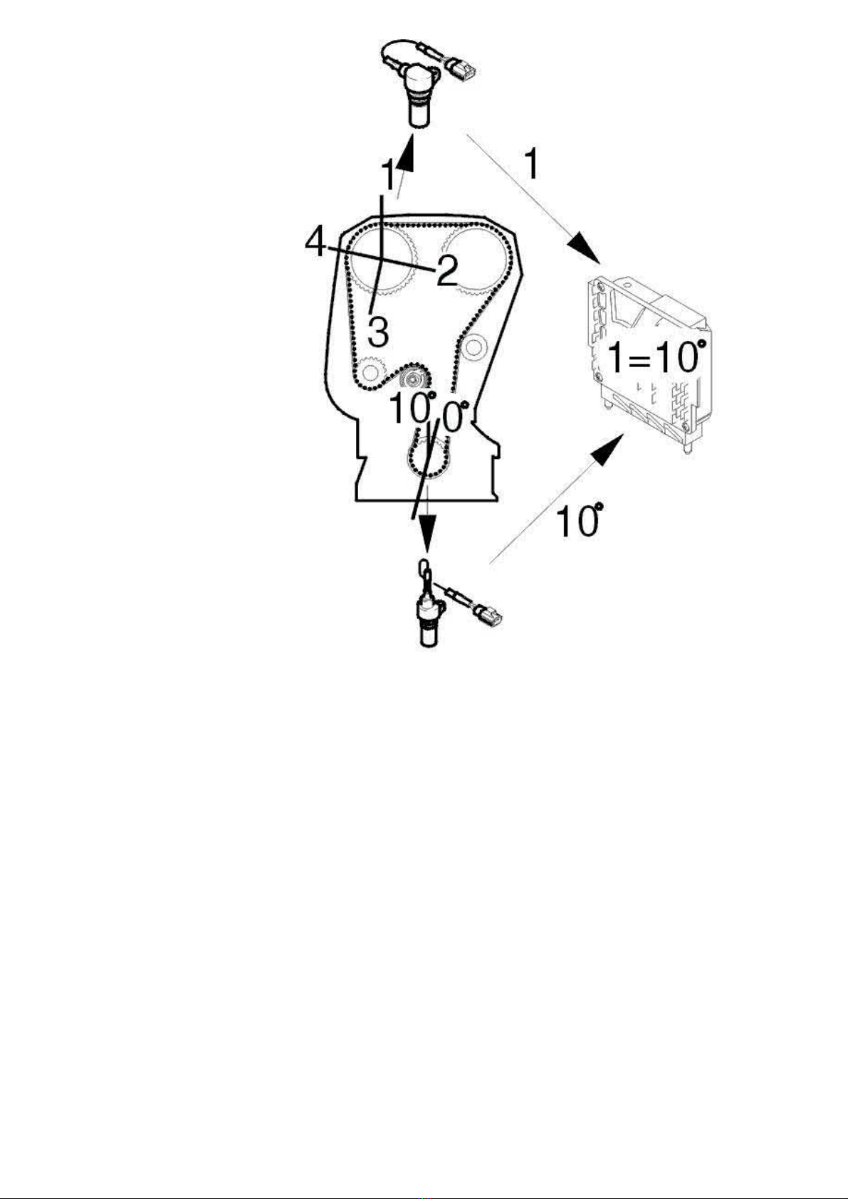
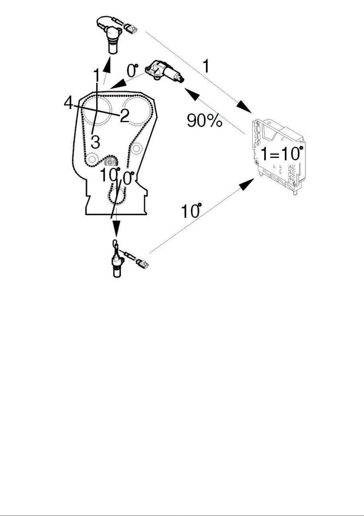
The control module interpretation of camshaft shift angle
(The illustration shows the camshaft shift angle at 10°)
The camshaft shift angle is checked by the control module by comparing the position of the crankshaft with the position of the camshaft.
The camshaft (A) is divided into 4 flanks per camshaft rotation (flanks 1-4). The angles are: between flanks 1-2 = 103°, flanks 2-3 = 90°, flanks 3-4
= 90° and flanks 4-1= 77°. The difference in angle between the flanks allows the control module to determine which flank is currently detected and
therefore which cycle the camshaft is in. The control module detects the flanks using the signal from the camshaft position (CMP) sensor.
The crankshaft has four reference positions, one for each camshaft flank. Two reference positions are detected for each crankshaft rotation. Two
engine rotations are required to detect all the camshaft flanks: flank 1 at 0°, flank 2 at 206°, flank 3 at 386° and flank 4 at 576° (flanks 3 and 4 are
detected during the second rotation of the engine).
The reference positions on the crankshaft correspond exactly to the respective camshaft flank when the camshaft shift angle = 0°. The control
module detects the reference positions for the camshaft flanks using the engine speed (RPM) sensor signal.
If, for example, the camshaft shift angle is +10°, the flanks correspond to the crankshaft reference positions for the respective camshaft flank and
+10° from the crankshaft reference positions.
Example:
If the camshaft flank 1 is detected at 10° from the crankshaft reference position for flank 1 (0° +10°), the camshaft shift angle is 10°. If the camshaft
shift angle is the same (10°), flank 2 is detected at 216° (206° + 10°), flank 3 at 396° (386° + 10°), and flank 4 at 576° (586° + 10°). The shift angle
can be positive (+) or negative (-) depending on whether the flank is detected before or after the different crankshaft reference positions.
Page 52
2005 Volvo XC70 L5-2.5L Turbo VIN 59 B5254T2 Copyright © 2011, ALLDATA 10.40 Page 3
gg
gggggggggggggggggggggg
Adaptation of the camshaft shift angle, flanks 1-4
(The illustration shows the adaptation of the camshaft shift angle at 10°)
When the engine has the "basic setting", the ideal value for the camshaft adaptation value is 0°. The different camshaft flanks correspond exactly
with the reference positions for the respective flanks. These values may deviate because of tolerances in the materials and installation. By adapting
these deviations the camshaft shift angle can be exact.
Adaptation is carried out as follows:
Camshaft control not active, the pulse ratio on the camshaft reset valve is set to approximately 90% by the control module. This means that the
camshaft 0 position (mechanical resting position) is assumed and the camshaft angles (x°) for flanks 1-4, which are then detected by the control
module, are the adaptation values which are stored. (The adaptation values will be 0° if the camshaft adjustment in relation to the crankshaft is
exact). When the control module operates the camshaft to a particular target value, the stored adaptation value is added to the control module's
target value.
Example: The control module has adapted flanks 1-4 to an average value of +10° (as the result of an incorrectly set camshaft for example). When
the control module needs to operate the camshaft to +10° (target value), the adaptation value is added to the target value which then gives a target
value of 20° (10° +10°=20°).
The control module can adapt ±20°. A diagnostic trouble code (DTC) is stored in the control module if the adaptation is higher or lower than ±10°.
Other information:
- If the timing belt is incorrectly positioned by one tooth on the variable valve timing unit, this corresponds to approximately 17° on the
crankshaft. This gives a theoretical adaptation value of 17°.
- If the timing belt is incorrectly positioned by one tooth on the variable valve timing unit, this corresponds to approximately 34° on the
crankshaft. This gives a maximum adaptation value (20°)
- The setting of the variable valve timing unit in relation to the camshaft and crankshaft affects the adaptation value (between -20° and +20°)
- If the slide in the camshaft reset valve has jammed, the camshaft will be operate at maximum angle. This which will give an adaptation value
at the maximum limit (+20° or -20°)
- The function of the variable valve timing unit affects the adaptation value (between -20° and +20°).
Page 53
2005 Volvo XC70 L5-2.5L Turbo VIN 59 B5254T2 Copyright © 2011, ALLDATA 10.40 Page 1
gg
gggggggggggggggggggggg
Variable Valve Timing Actuator: Testing and Inspection
Variable valve timing unit, checking and adjusting
Special tools:
999 5451 ADJUSTMENT TOOL See: Tools and Equipment/999 5451 Adjustment Tool
999 5452 CAMSHAFT ADJUSTMENT TOOL See: Tools and Equipment/999 5452 Camshaft Adjustment Tool
Note! The illustrations in this service information are used for different model years and/or models. Some variation may occur. However,
the essential information in the illustrations is always correct.
Installing and adjusting the variable valve timing unit/timing gear pulley on the camshaft
Note! This procedure must be carried out with precision as any deviation could generate a fault symptom.
Installing the crankshaft adjustment tool
Remove the mounting screws for the starter motor.
Pull out the starter motor and place it to one side.
Remove the blind cover plug from the hole for the adjustment tool.
Turn the crankshaft clockwise slightly.
Install: 999 5451 ADJUSTMENT TOOL See: Tools and Equipment/999 5451 Adjustment Tool. Ensure that the tool bottoms out against the
cylinder block.
Aligning the crankshaft
Turn the crankshaft counter-clockwise until it stops against the adjustment tool.
Check that the marking on the crankshaft timing gear pulley corresponds to the marking on the oil pump.
Installing the variable valve timing unit on the camshaft
Page 54
2005 Volvo XC70 L5-2.5L Turbo VIN 59 B5254T2 Copyright © 2011, ALLDATA 10.40 Page 2
gg
gggggggggggggggggggggg
Note! Oil the center screw before installation
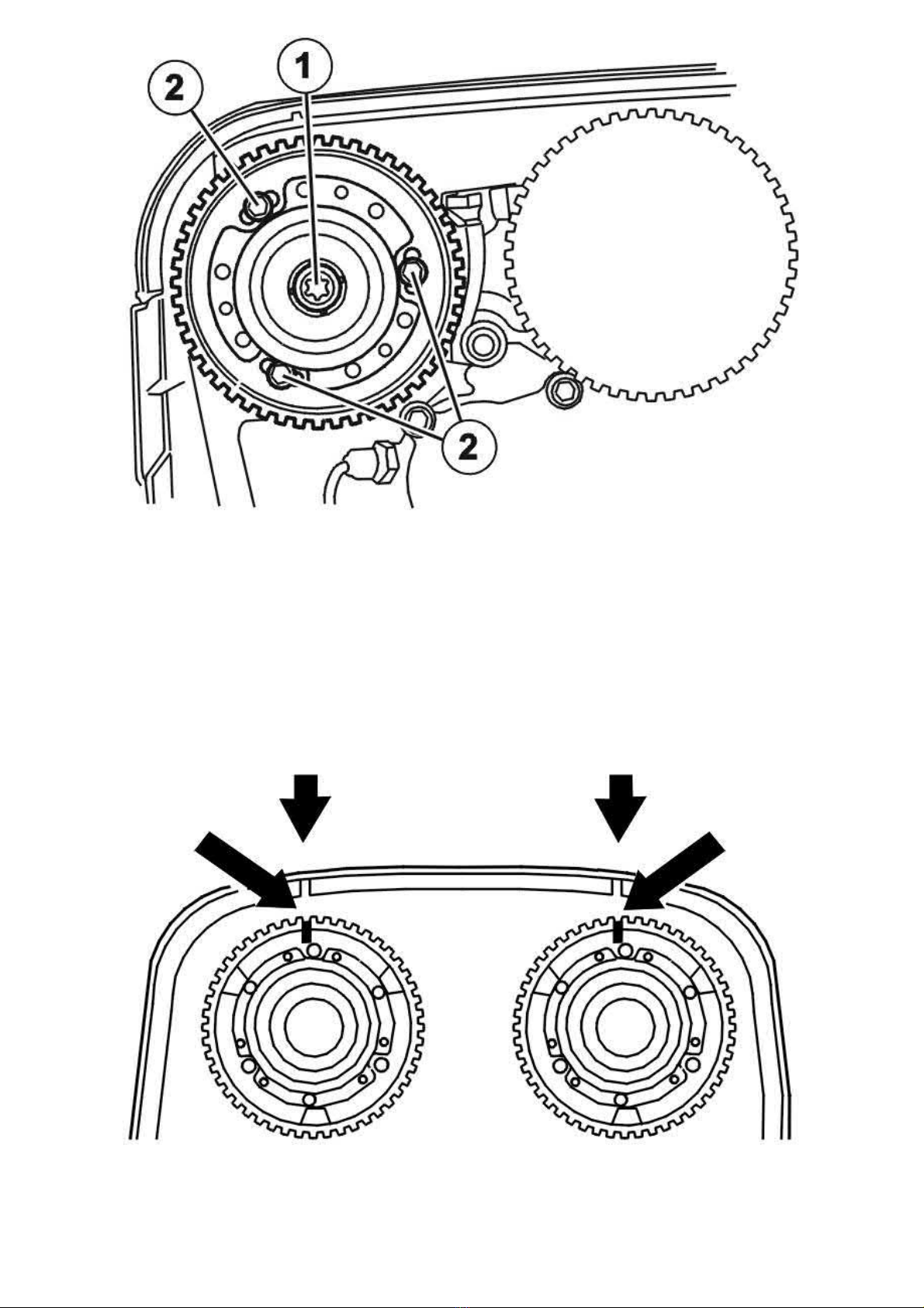
Push on the variable valve timing unit/timing gear pulley on the camshaft.
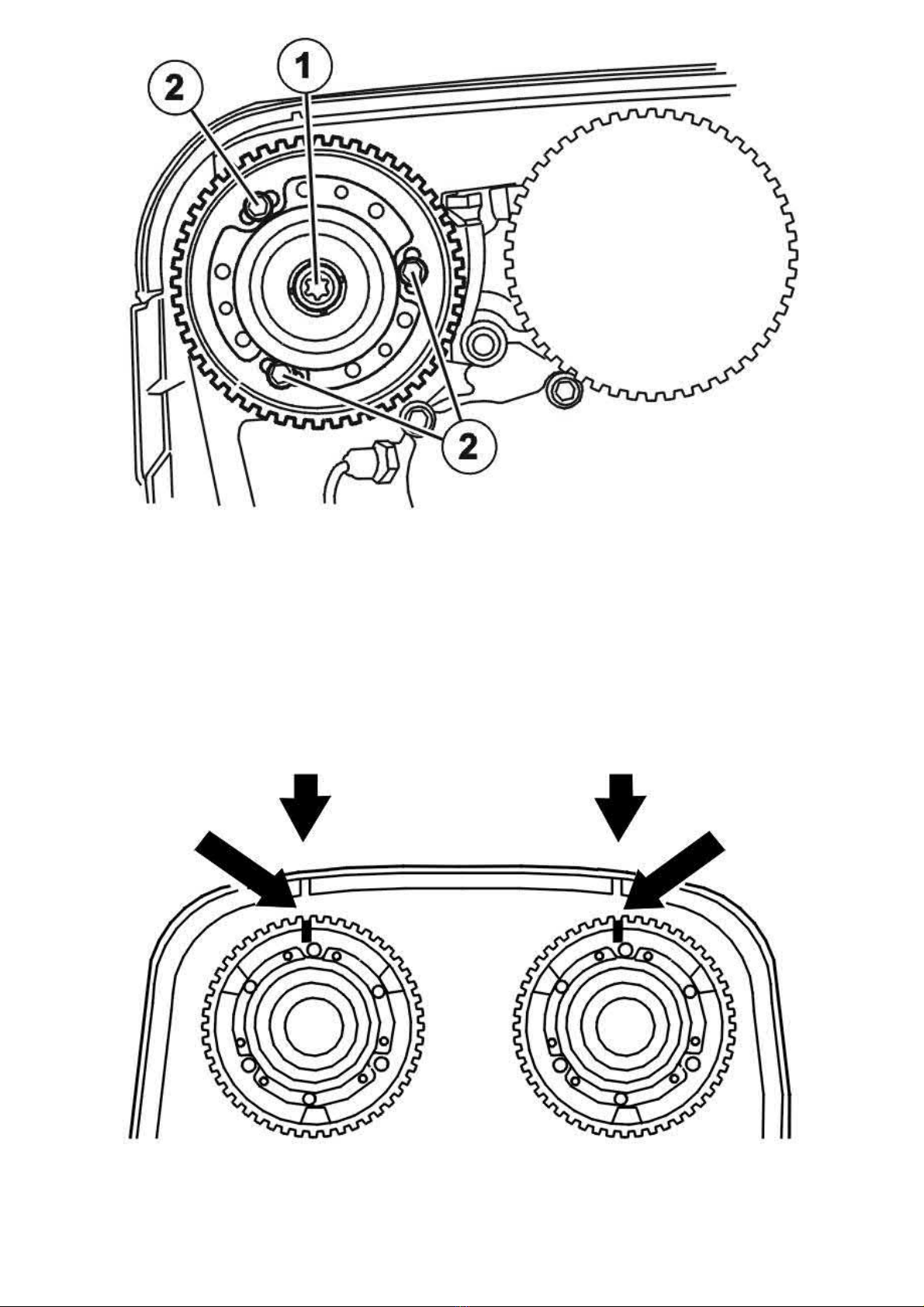
Install the center screw (1) which secures the variable valve timing unit to the camshaft. Tighten slightly.
Slacken off, but do not remove the screws (2) which secure the timing gear pulley to the variable valve timing unit.
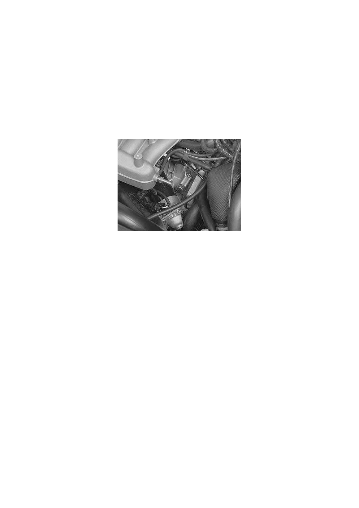
Turn the timing gear pulley until the screws at the oval holes are in the center position. Tighten the screws (2) slightly.
Turn the variable valve timing unit clockwise to its limit position so that the unit is in its end position.
Position the upper timing cover
Undo the center screw and continue turning clockwise until the timing gear pulley marking aligns with the marking on the upper timing cover.
Page 55
2005 Volvo XC70 L5-2.5L Turbo VIN 59 B5254T2 Copyright © 2011, ALLDATA 10.40 Page 3
gg
gggggggggggggggggggggg
Tighten the center screw in the variable valve timing unit. Tighten. See: Tightening torque See: Specifications/Tightening Torque.
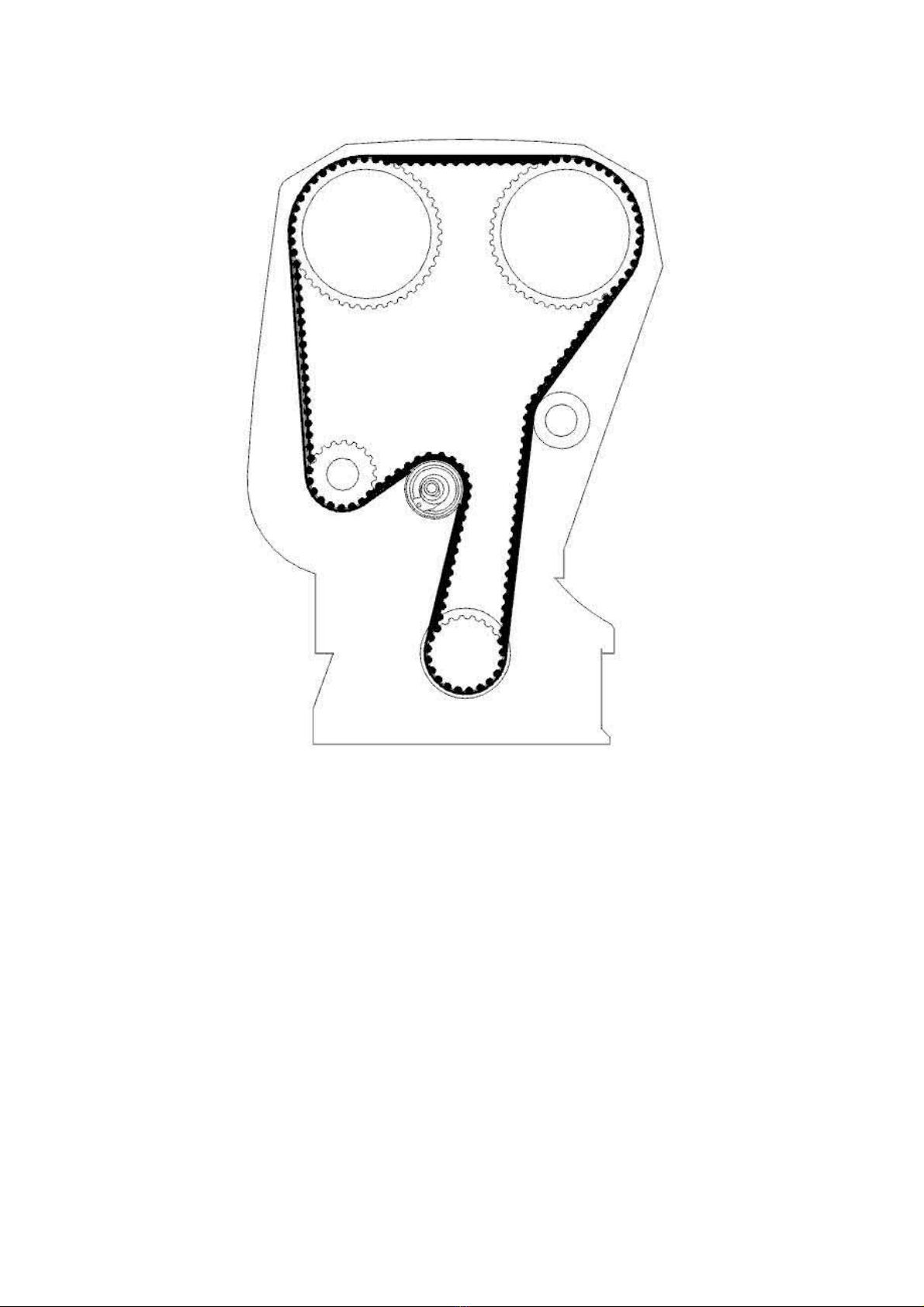
Installing the timing belt
Note! Variable valve timing units do not have return springs and are easily thrown out of position when the camshaft belt is installed.
Check that the markings align.
Install the belt in the following order:
- the idler pulley
- intake cam
- exhaust cam
- water pump
- tension pulley.
Tensioning of cambelt
Page 56
2005 Volvo XC70 L5-2.5L Turbo VIN 59 B5254T2 Copyright © 2011, ALLDATA 10.40 Page 4
gg
gggggggggggggggggggggg
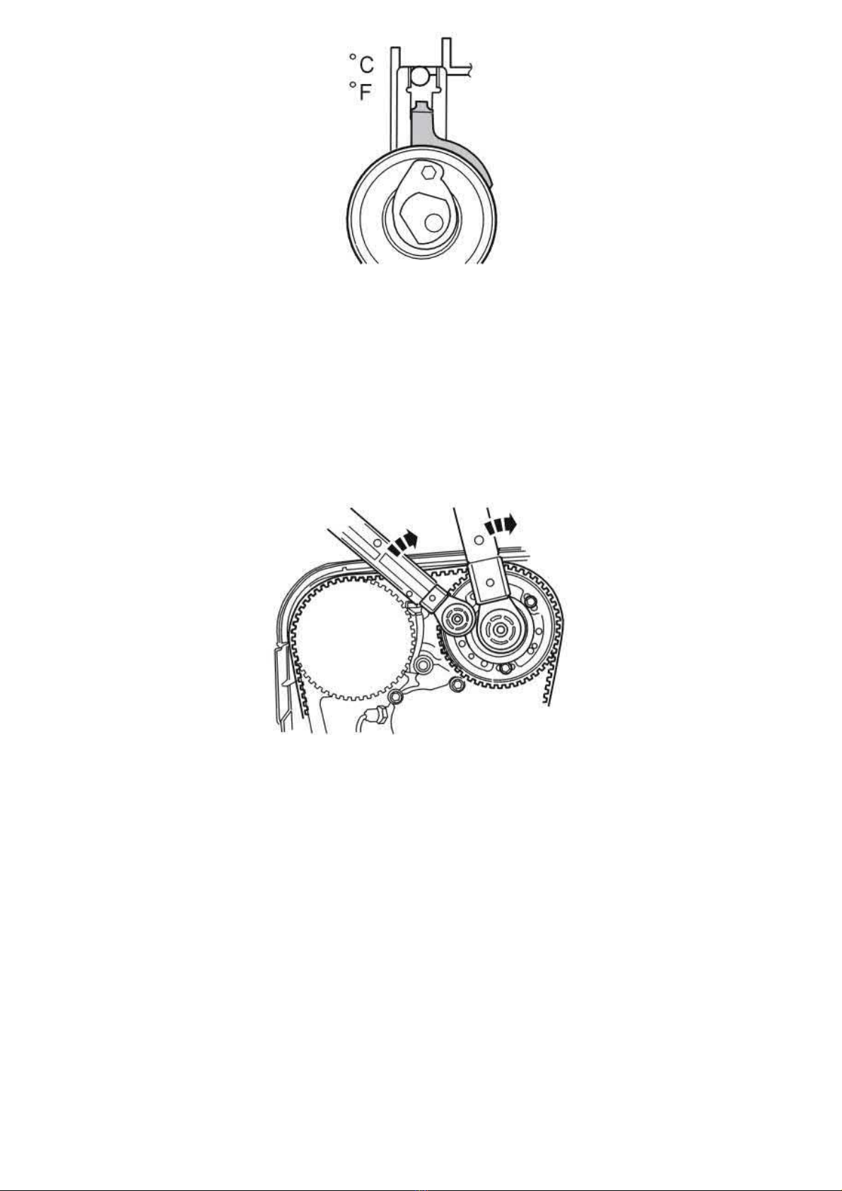
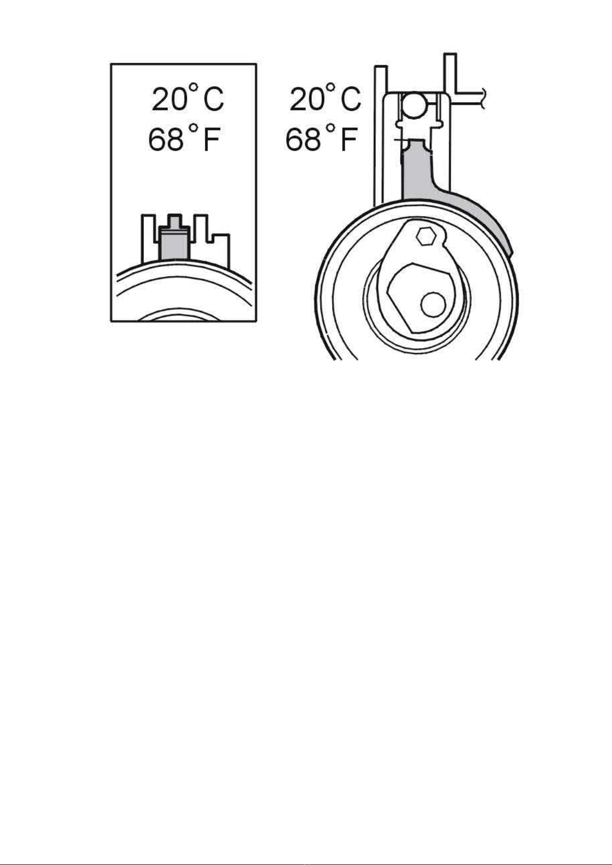
This adjustment is to be made with a cold engine.
A suitable temperature is approximately 20 °C/68 °F.
At a higher temperature, for example with a warm engine or a higher ambient temperature, the needle is further to the right.
The illustration shows the position of the indicator when aligning the timing belt tensioner at approximately 20 °C/68 °F.
Note! There are two different tensioners depending on model year.
Fix the belt tensioner center screw in position and turn the belt tensioner eccentric clockwise until the tensioner indicator passes the marked position
and reaches the end position. Then turn the eccentric back so the indicator reaches the marked position illustrated. Tighten the center screw. See
Tightening torque See: Specifications/Tightening Torque.
Check that the indicator is in the correct position.
Tightening
Slacken off the 3 x screws for the timing gear pulley slightly (applies to both timing gear pulleys).
Install the center plug in the variable valve timing unit. Tighten. See: Tightening torque See: Specifications/Tightening Torque.
Hold the center plug at 25 Nm at the same time as tightening the 3 x screws on the camshaft timing gear pulley to: Tightening torque See:
Specifications/Tightening Torque.
Tighten the 3 x screws on the timing gear pulley for the intake camshaft. See: Tightening torque See: Specifications/Tightening Torque. This is to
ensure that the variable valve timing (VVT) unit is in its end position when the timing gear pulley is tightened.
Final check
Page 57
2005 Volvo XC70 L5-2.5L Turbo VIN 59 B5254T2 Copyright © 2011, ALLDATA 10.40 Page 5
gg
gggggggggggggggggggggg
Remove:
- 999 5452 CAMSHAFT ADJUSTMENT TOOL See: Tools and Equipment/999 5452 Camshaft Adjustment Tool from the rear of the
camshafts
- 999 5451 ADJUSTMENT TOOL See: Tools and Equipment/999 5451 Adjustment Tool. Install new plugs with new sealing washers.
Tighten. See: Tightening torque See: Specifications/Tightening Torque.
Checking the markings and belt tension.
Position the upper timing cover.
Turn the crankshaft 2 rotations. Check that the markings on the crankshaft and timing gear pulleys correspond.
Remove the upper timing cover.
Page 58
2005 Volvo XC70 L5-2.5L Turbo VIN 59 B5254T2 Copyright © 2011, ALLDATA 10.40 Page 1
gg
gggggggggggggggggggggg
Variable Valve Timing Actuator: Adjustments
Variable valve timing unit, checking and adjusting
Special tools:
999 5451 ADJUSTMENT TOOL See: Tools and Equipment/999 5451 Adjustment Tool
999 5452 CAMSHAFT ADJUSTMENT TOOL See: Tools and Equipment/999 5452 Camshaft Adjustment Tool
Note! The illustrations in this service information are used for different model years and/or models. Some variation may occur. However,
the essential information in the illustrations is always correct.
Installing and adjusting the variable valve timing unit/timing gear pulley on the camshaft
Note! This procedure must be carried out with precision as any deviation could generate a fault symptom.
Installing the crankshaft adjustment tool
Remove the mounting screws for the starter motor.
Pull out the starter motor and place it to one side.
Remove the blind cover plug from the hole for the adjustment tool.
Turn the crankshaft clockwise slightly.
Install: 999 5451 ADJUSTMENT TOOL See: Tools and Equipment/999 5451 Adjustment Tool. Ensure that the tool bottoms out against the
cylinder block.
Aligning the crankshaft
Turn the crankshaft counter-clockwise until it stops against the adjustment tool.
Check that the marking on the crankshaft timing gear pulley corresponds to the marking on the oil pump.
Installing the variable valve timing unit on the camshaft
Page 59
2005 Volvo XC70 L5-2.5L Turbo VIN 59 B5254T2 Copyright © 2011, ALLDATA 10.40 Page 2
gg
gggggggggggggggggggggg
Note! Oil the center screw before installation
Push on the variable valve timing unit/timing gear pulley on the camshaft.
Install the center screw (1) which secures the variable valve timing unit to the camshaft. Tighten slightly.
Slacken off, but do not remove the screws (2) which secure the timing gear pulley to the variable valve timing unit.
Turn the timing gear pulley until the screws at the oval holes are in the center position. Tighten the screws (2) slightly.
Turn the variable valve timing unit clockwise to its limit position so that the unit is in its end position.
Position the upper timing cover
Undo the center screw and continue turning clockwise until the timing gear pulley marking aligns with the marking on the upper timing cover.
Page 60

2005 Volvo XC70 L5-2.5L Turbo VIN 59 B5254T2 Copyright © 2011, ALLDATA 10.40 Page 3
gg
gggggggggggggggggggggg
Tighten the center screw in the variable valve timing unit. Tighten. See: Tightening torque See: Specifications/Tightening Torque.
Installing the timing belt
Note! Variable valve timing units do not have return springs and are easily thrown out of position when the camshaft belt is installed.
Check that the markings align.
Install the belt in the following order:
- the idler pulley
- intake cam
- exhaust cam
- water pump
- tension pulley.
Tensioning of cambelt
Page 61
2005 Volvo XC70 L5-2.5L Turbo VIN 59 B5254T2 Copyright © 2011, ALLDATA 10.40 Page 4
gg
gggggggggggggggggggggg
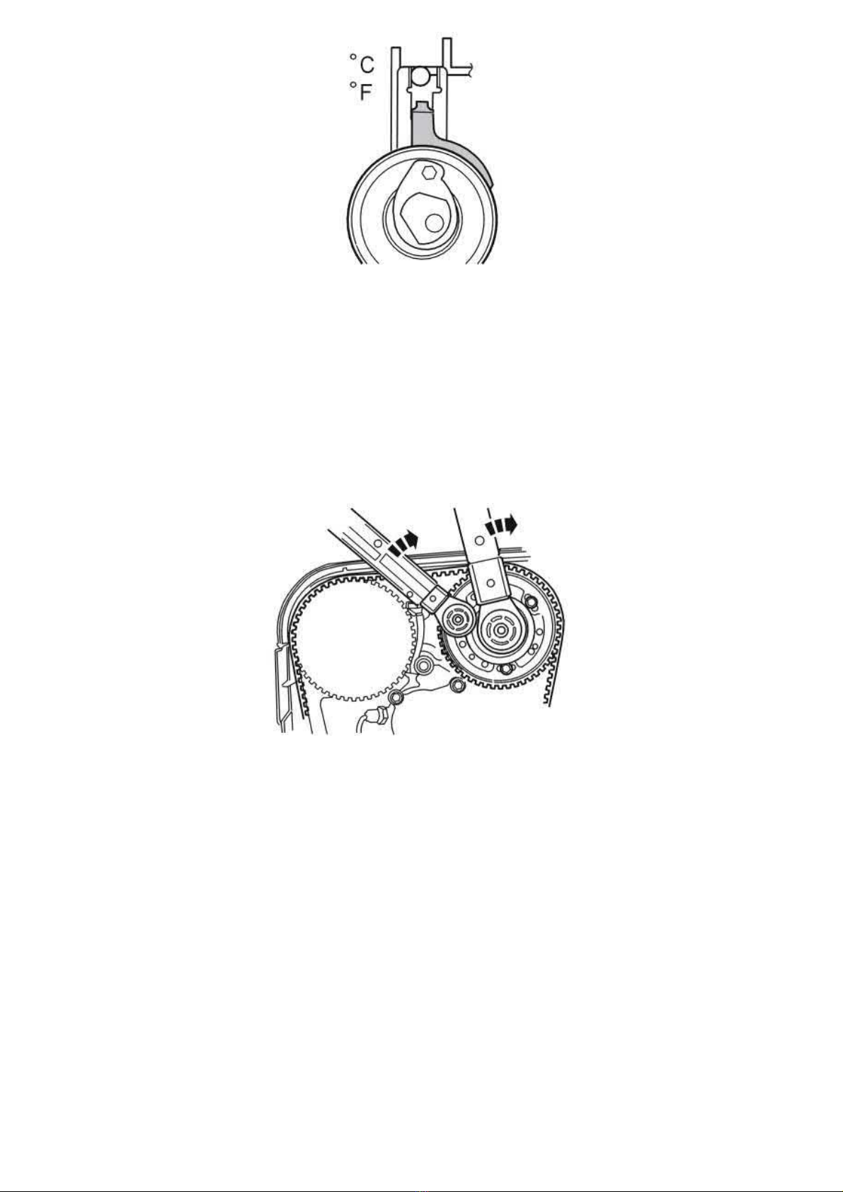
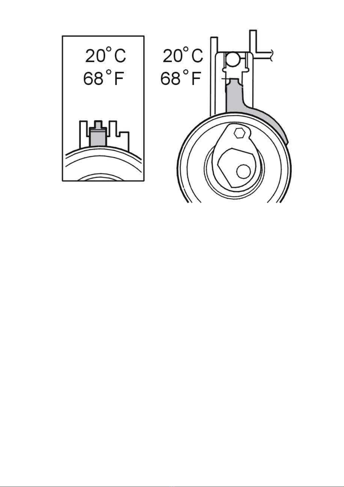
This adjustment is to be made with a cold engine.
A suitable temperature is approximately 20 °C/68 °F.
At a higher temperature, for example with a warm engine or a higher ambient temperature, the needle is further to the right.
The illustration shows the position of the indicator when aligning the timing belt tensioner at approximately 20 °C/68 °F.
Note! There are two different tensioners depending on model year.
Fix the belt tensioner center screw in position and turn the belt tensioner eccentric clockwise until the tensioner indicator passes the marked position
and reaches the end position. Then turn the eccentric back so the indicator reaches the marked position illustrated. Tighten the center screw. See
Tightening torque See: Specifications/Tightening Torque.
Check that the indicator is in the correct position.
Tightening
Slacken off the 3 x screws for the timing gear pulley slightly (applies to both timing gear pulleys).
Install the center plug in the variable valve timing unit. Tighten. See: Tightening torque See: Specifications/Tightening Torque.
Hold the center plug at 25 Nm at the same time as tightening the 3 x screws on the camshaft timing gear pulley to: Tightening torque See:
Specifications/Tightening Torque.
Tighten the 3 x screws on the timing gear pulley for the intake camshaft. See: Tightening torque See: Specifications/Tightening Torque. This is to
ensure that the variable valve timing (VVT) unit is in its end position when the timing gear pulley is tightened.
Final check
Page 62
2005 Volvo XC70 L5-2.5L Turbo VIN 59 B5254T2 Copyright © 2011, ALLDATA 10.40 Page 5
gg
gggggggggggggggggggggg
Remove:
- 999 5452 CAMSHAFT ADJUSTMENT TOOL See: Tools and Equipment/999 5452 Camshaft Adjustment Tool from the rear of the
camshafts
- 999 5451 ADJUSTMENT TOOL See: Tools and Equipment/999 5451 Adjustment Tool. Install new plugs with new sealing washers.
Tighten. See: Tightening torque See: Specifications/Tightening Torque.
Checking the markings and belt tension.
Position the upper timing cover.
Turn the crankshaft 2 rotations. Check that the markings on the crankshaft and timing gear pulleys correspond.
Remove the upper timing cover.
Page 63
2005 Volvo XC70 L5-2.5L Turbo VIN 59 B5254T2 Copyright © 2011, ALLDATA 10.40 Page 1
gg
gggggggggggggggggggggg
Variable Valve Timing Actuator: Service and Repair
Camshaft Seal/Variable Valve Timing (VVT) Unit, Replacing
Camshaft seal/variable valve timing (VVT) unit, replacing
Special tools:
999 5452 CAMSHAFT ADJUSTMENT TOOL See: Tools and Equipment/999 5452 Camshaft Adjustment Tool
999 5651 Extractor See: Tools and Equipment/999 5651 Extractor
999 5719 Drift See: Tools and Equipment/999 5719 Drift
999 5718 Drift See: Tools and Equipment/999 5718 Drift
999 5474 RADIATOR PROTECTION See: Tools and Equipment/999 5474 Radiator Protection
999 5451 ADJUSTMENT TOOL See: Tools and Equipment/999 5451 Adjustment Tool
999 5919 PULLER See: Tools and Equipment/999 5919 Puller
999 5450 PUNCH See: Tools and Equipment/999 5450 Punch
Note! As the illustrations in this service information are used for different model years and / or models, some variation may occur.
However, the essential information is always correct.
Removal
Caution! There are a number of versions of the variable valve timing unit. Therefore it is extremely important to always read the
information referring to the engine variant/model year to be remedied.
Removing the camshaft seal
Note! Crankshaft and camshafts must not be turned more than is stated in the method description!If the shafts are turned in any other
way the valves may be damaged.
Remove:
- the cable from the battery negative terminal.
First read
- the cross stay between the suspension turrets
- the air intake hose for the turbocharger (TC) from the air cleaner (ACL) cover. Put to one side
- the upper timing belt cover
- the cover over the ignition coils
- the upper engine stabilizer brace
- the camshaft position (CMP) sensor housing
- the trigger wheel
- the servo reservoir and the expansion tank. Lift up and place on top of the engine.
Battery, disconnecting See: Starting and Charging/Battery/Service and Repair/Procedures/Battery, Disconnecting.
Warning! Ensure that no power steering fluid is spilled. Extremely flammable.
- the auxiliaries belt
- the front timing belt cover.
Aligning the engine according to the marking
Page 64
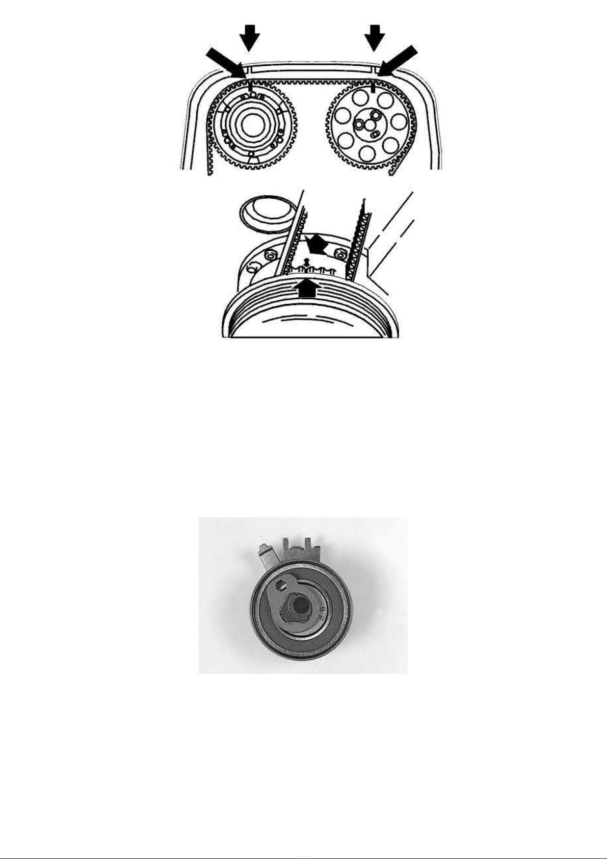
2005 Volvo XC70 L5-2.5L Turbo VIN 59 B5254T2 Copyright © 2011, ALLDATA 10.40 Page 2
gg
gggggggggggggggggggggg
Raise the car.
Remove:
- the right front wheel
- the nuts for the cover in the wing liner.
Install the upper timing belt cover.
Turn the crankshaft clockwise until the markings on the crankshaft and camshaft pulley correspond.
Turn the crankshaft a further 1/4 of a turn clockwise, then turn back counter-clockwise until the markings correspond.
The markings are illustrated.
Remove the upper timing belt cover.
Removing the timing belt
- Slacken off the belt tensioner
- Slacken off the centre screw for the belt tensioner slightly
- Hold the centre screw still. Turn the tensioner eccentric clockwise to 10 o'clock using a 6 mm Allen key
- Remove the timing belt from the camshaft pulleys.
Removing the timing gear pulley with the variable valve timing unit
Page 65
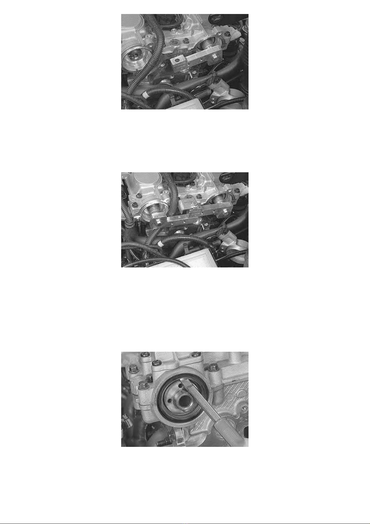
2005 Volvo XC70 L5-2.5L Turbo VIN 59 B5254T2 Copyright © 2011, ALLDATA 10.40 Page 3
gg
gggggggggggggggggggggg
Use camshaft adjustment tool:
- Install camshaft adjustment tool 999 5452 CAMSHAFT ADJUSTMENT TOOL See: Tools and Equipment/999 5452 Camshaft Adjustment
Tool at the rear of the camshafts.
- First screw in the part of the tool intended for the exhaust camshaft (drilled hole)
- Then carefully turn the exhaust camshaft clockwise with the camshaft adjustment tool until the intake camshaft tool can be applied (threaded
hole)
- Install the intake camshaft adjustment tool.
Screw the camshaft adjustment tools together.
Remove:
- the plug at the front edge of the variable valve timing unit (TORX 55)
- the centre screw in the variable valve timing unit (TORX 55). Carefully pull out the timing gear pulley with the variable valve timing (VVT)
unit.
Note! Use paper to collect any spilled oil under the variable valve timing units.
Replacing the camshaft seal
Carefully press in tool 999 5651 Extractor See: Tools and Equipment/999 5651 Extractor between the sealing ring and the camshaft. Carefully pry
out the seal.
Cleaning
To clean the shaft journal and mating surface, use emery cloth P/N 951 1024.
Page 66
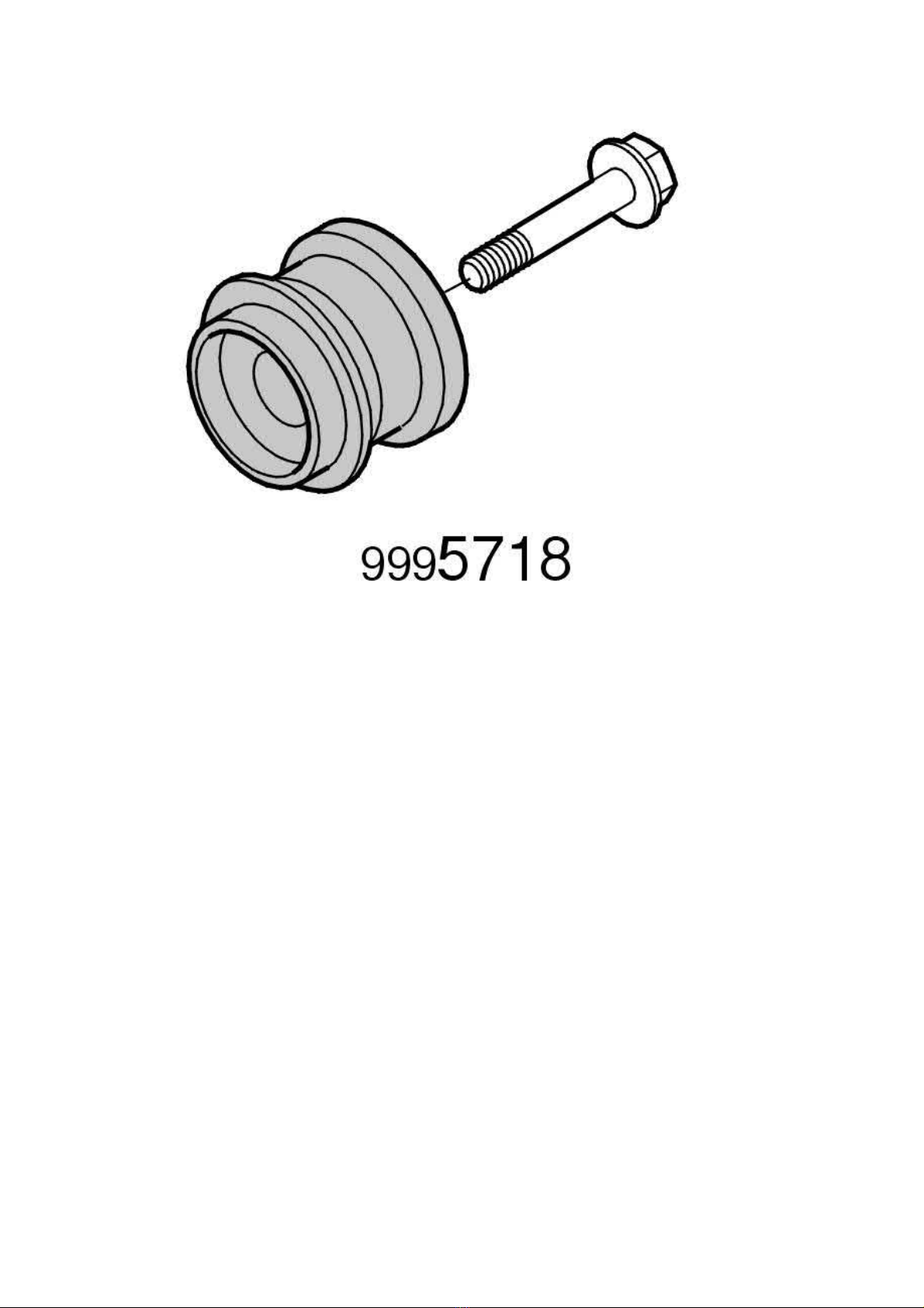
2005 Volvo XC70 L5-2.5L Turbo VIN 59 B5254T2 Copyright © 2011, ALLDATA 10.40 Page 4
gg
gggggggggggggggggggggg
Note! When cleaning work around the shaft journal, not in and out. It is essential that any residue from the emery cloth and any other
contaminants are completely removed before the new sealing ring is installed.
Lubricate the new seal. Install the new seal for the exhaust camshaft. Use drift 999 5718 Drift See: Tools and Equipment/999 5718 Drift.
Installation
Checking and adjusting the variable valve timing unit
Check and adjust the variable valve timing unit.
Installing components
Install:
- the front timing belt cover.
- the torque rod bracket
- the cover over the ignition coils
- the upper timing belt cover
- the auxiliaries belt
- the expansion tank
- the servo reservoir. Check that the hoses are correctly positioned
- the starter motor. Tighten the screws at the gearbox to
- the charge air pipe between the throttle body (TB) and the charge air cooler (CAC).
. Tighten the support bracket screw to
40 Nm
25 Nm
Page 67
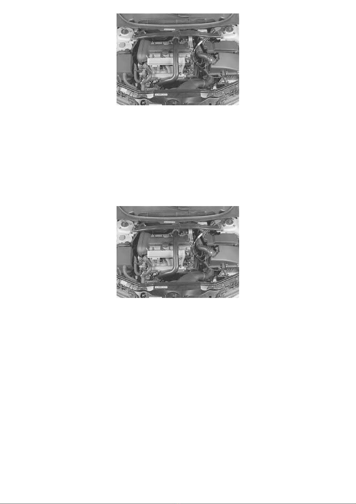
2005 Volvo XC70 L5-2.5L Turbo VIN 59 B5254T2 Copyright © 2011, ALLDATA 10.40 Page 5
gg
gggggggggggggggggggggg
Install:
- the trigger wheel
- the camshaft position (CMP) sensor housing and a new cover
- the intake air hose between the turbocharger (TC) and the air cleaner (ACL) cover
- the engine stabilizer brace. Tighten the screws at the suspension turrets and the screw for motor bracket
- the negative battery cable.
Disconnecting.
Checking the engine
First read
Battery, disconnecting See: Starting and Charging/Battery/Service and Repair/Procedures/Battery,
Test drive the car to check the function of the engine.
Replacing the rear seal
The following components must be removed when replacing the rear seal:
- the cross stay between the suspension turrets
- the air hose from the air cleaner (ACL) to the turbocharger (TC). Place to one side. Seal the openings
- place the air cleaner (ACL) cover to one side
- the charge air pipe over the engine. Seal the openings
- the cover over the ignition coils
- the upper torque rod bracket
- the camshaft position sensor (CMP) housing and trigger wheel.
Replacing the rear camshaft seal
Page 68
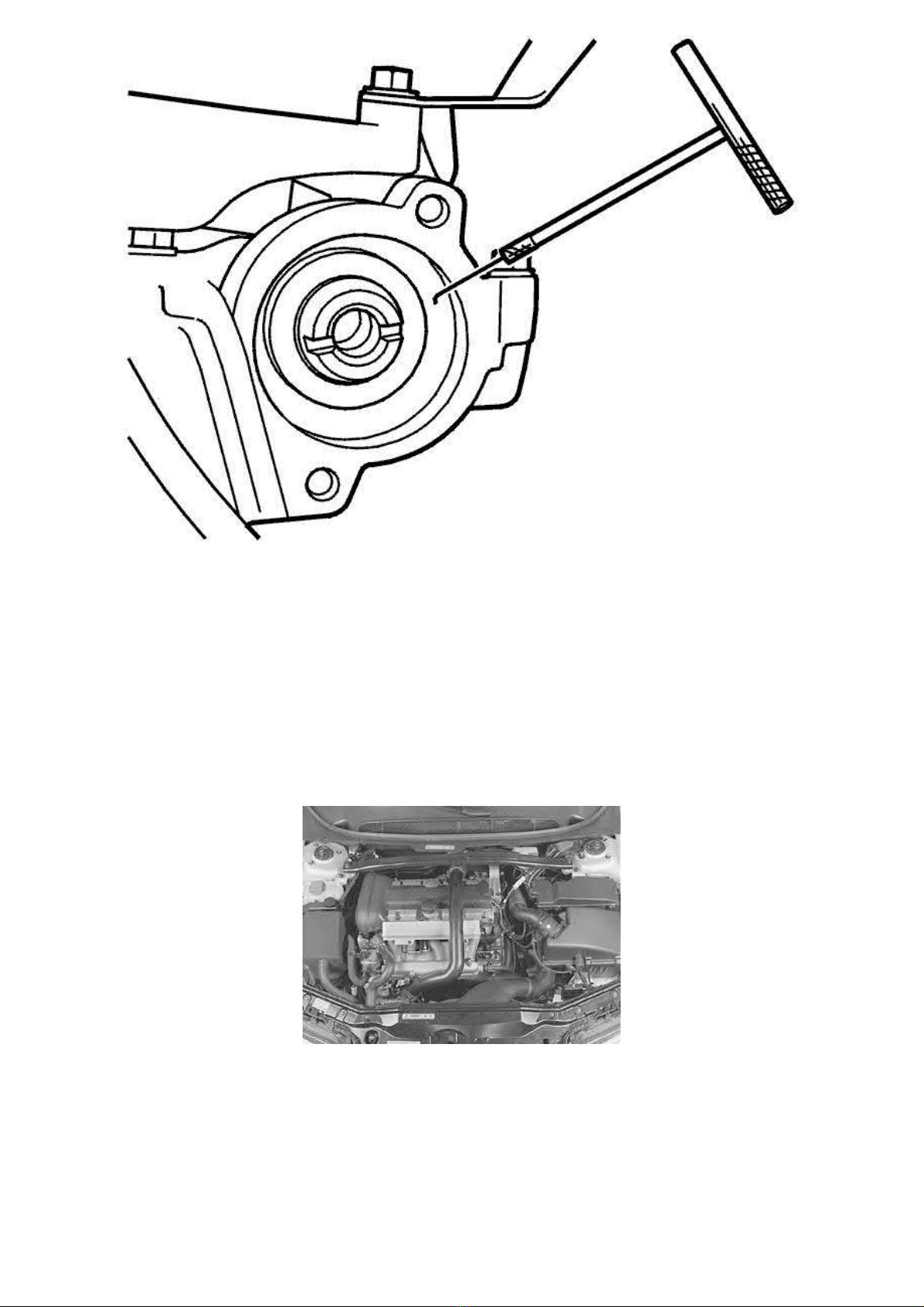
2005 Volvo XC70 L5-2.5L Turbo VIN 59 B5254T2 Copyright © 2011, ALLDATA 10.40 Page 6
gg
gggggggggggggggggggggg
Pull out the seal. Use puller 999 5919 PULLER See: Tools and Equipment/999 5919 Puller. Use emery cloth 951 1024 to clean the shaft journal
and mating surface.
Note! When cleaning work around the shaft journal, not in and out. It is essential that any residue from the emery cloth and any other
contaminants are completely removed before the new sealing ring is installed.
Lubricate the surface of the seal that the camshaft rotates against. Install the camshaft seal. Use drift 999 5450 PUNCH See: Tools and
Equipment/999 5450 Punch.
Note! The seal is normally pressed in so that it is level with the internal bevelled edge.If the shaft journal is showing signs of wear, the seal
can be pressed in 2 mm deeper by turning the drift socket.
Installing components
Install:
- the trigger wheel
- the camshaft position (CMP) sensor housing and a new cover
- the torque rod bracket. Tighten
- the cover over the ignition coils
- the charge air pipe over the engine. Remove the seals
- the air cleaner (ACL) cover and the intake air hose
- the engine stabilizer brace. Tighten the screws at the suspension turrets and the screw for motor bracket
Check the engine compartment. Wipe the engine compartment clean.
Page 69
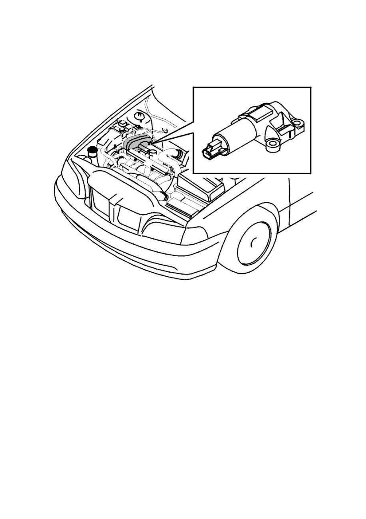
2005 Volvo XC70 L5-2.5L Turbo VIN 59 B5254T2 Copyright © 2011, ALLDATA 10.40 Page 1
gg
gggggggggggggggggggggg
Variable Valve Timing Actuator: Service and Repair
Variable Valve Timing Solenoid, Replacing
Variable valve timing solenoid, replacing
All models
Removing the variable valve timing (VVT) control valve
Remove
- the upper timing belt cover.
Note! Clean the area around the variable valve timing (VVT) valve thoroughly to prevent anything else than clean oil from entering the
channels/ variable valve timing (VVT) valve.
Page 70
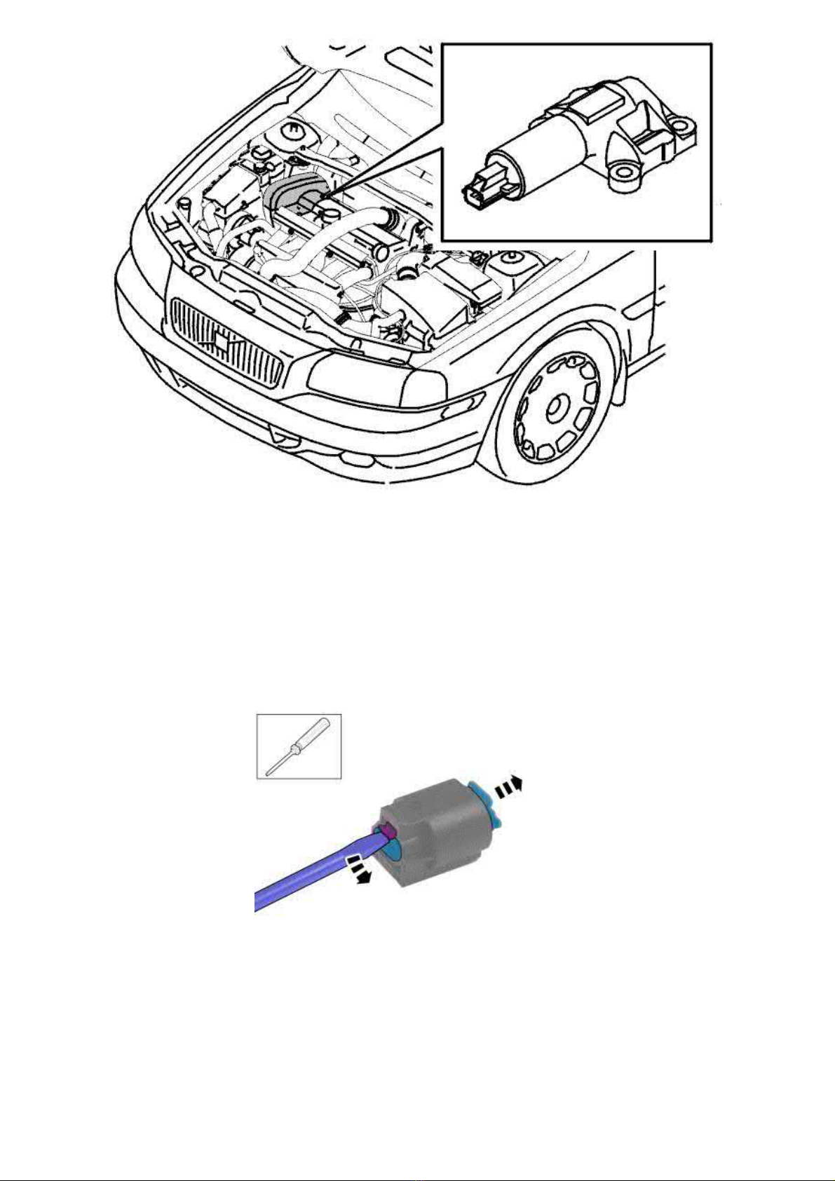
2005 Volvo XC70 L5-2.5L Turbo VIN 59 B5254T2 Copyright © 2011, ALLDATA 10.40 Page 2
gg
gggggggggggggggggggggg
- the connector for the check valve
- the screws holding the valve
- the control valve and the gasket.
Applies to B5244Sx model years 1999-2001
A modified VVT-solenoid is now available as spare part for
replaced. Note! Note the position of the electric connections. Cut the cables next to the connector.
Note! Note the position of the electric connections.
Cut the cables next to the connector.
B5244Sx model years 1999-2001
. This means that the connector on the cable must be
Press up the lock tab and pull out the seat for the connector pins from the casing.
Page 71
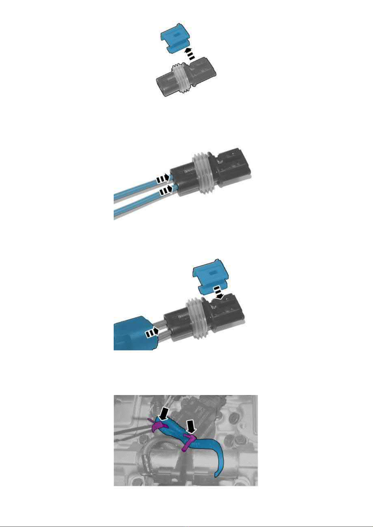
2005 Volvo XC70 L5-2.5L Turbo VIN 59 B5254T2 Copyright © 2011, ALLDATA 10.40 Page 3
gg
gggggggggggggggggggggg
Remove the lock
Caution! Make sure that the connector pins end up in the correct position.
Install the connector pins in the seat so that the locks on the pin end up in the opening on the side of the seat.
Install the catch.
Install the casing.
Splice the cables. Refer to: Joining the cables See: Cooling System/Coolant Level Sensor/Diagrams/Diagnostic Aids/Wiring/Joining the Cables
Caution! Make sure that the cable cannot enter the timing gears by clamping any excess cable with cable ties.
Page 72
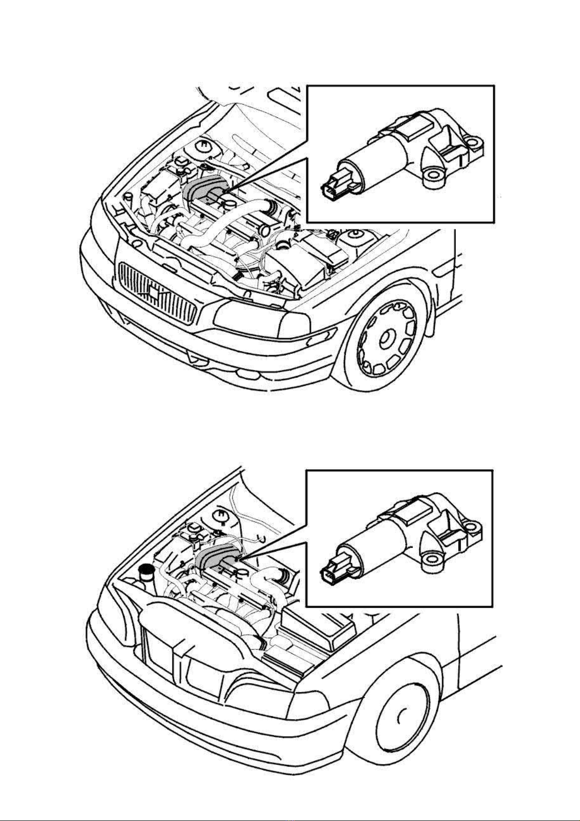
2005 Volvo XC70 L5-2.5L Turbo VIN 59 B5254T2 Copyright © 2011, ALLDATA 10.40 Page 4
gg
gggggggggggggggggggggg
Applies to all: Installing VVT-control valve
Clean the gasket faces. Note the cleanliness requirements above.
Install a
Install a new control valve. Tighten the control valve crosswise. Tighten to
Connect the connector.
new gasket
.
10 Nm
Page 73

2005 Volvo XC70 L5-2.5L Turbo VIN 59 B5254T2 Copyright © 2011, ALLDATA 10.40 Page 5
gg
gggggggggggggggggggggg
Install the upper timing belt cover.
Page 74
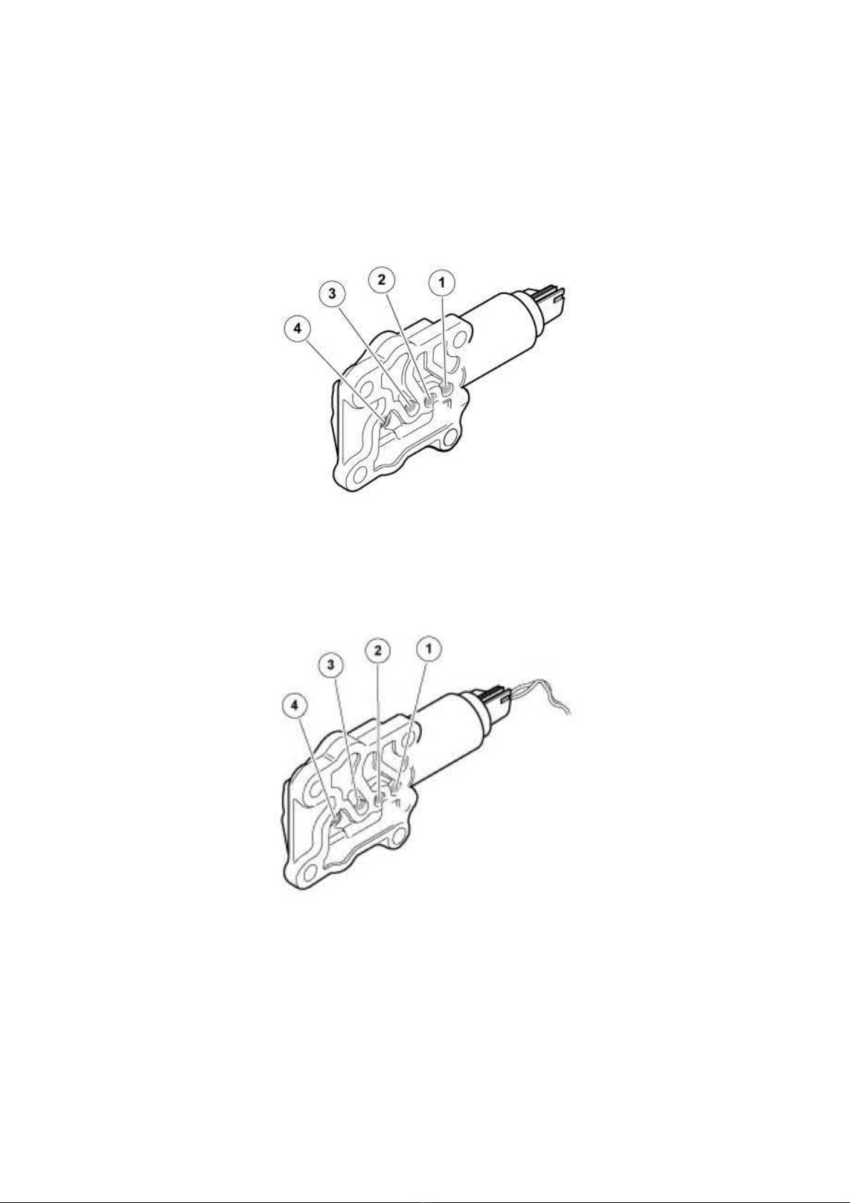
2005 Volvo XC70 L5-2.5L Turbo VIN 59 B5254T2 Copyright © 2011, ALLDATA 10.40 Page 1
gg
gggggggggggggggggggggg
Variable Valve Timing Solenoid: Procedures
VVT Solenoid, Cleaning
VVT solenoid, cleaning
Note! Some variation in the illustrations may occur, but the essential information is always correct.
Check
Remove the VVT solenoid.
Blow compressed air into the oil feed hole (2). Air should come out through the B port (1)
If the duct seems to be blocked, go to the cleaning step.
Connect current to the solenoid.
The solenoid should click. It may be easier to hear the click with the solenoid in your hand.
Blow compressed air into the oil feed hole (2). Air should come out through the A port (3). If the piston jams or the solenoid does not work, the
direction of flow will not change. If the duct seems to be blocked, go to the cleaning step.
Cleaning
Page 75
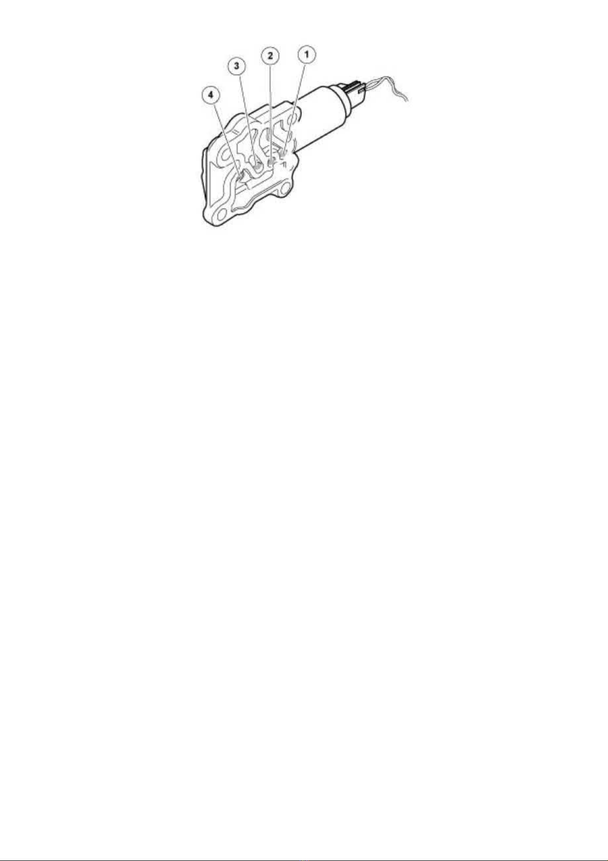
2005 Volvo XC70 L5-2.5L Turbo VIN 59 B5254T2 Copyright © 2011, ALLDATA 10.40 Page 2
gg
gggggggggggggggggggggg
cleaner, 1161826 (1161828 US)
Use:
Allow to act for 5 minutes.
Blow compressed air into all holes from both directions and look for contamination. Carry this out with current on and off to ensure that no dirt
remains in the ducts.
Rinse with cleaning agent.
cleaning agent, 1161721.
Use:
Blow again.
Lubricate the solenoid with engine oil to prevent it jamming.
After cleaning, check the function by repeating steps 1 and 2 again. If the solenoid still does not work after cleaning twice, replace the solenoid.
Test driving and checking
Erase Diagnostic Trouble Codes (DTCs).
Test drive the car.
Check that no new DTCs have been stored.
VVT Solenoid, Inspection and Cleaning
VVT solenoid, inspection and cleaning
Inspection
Page 76
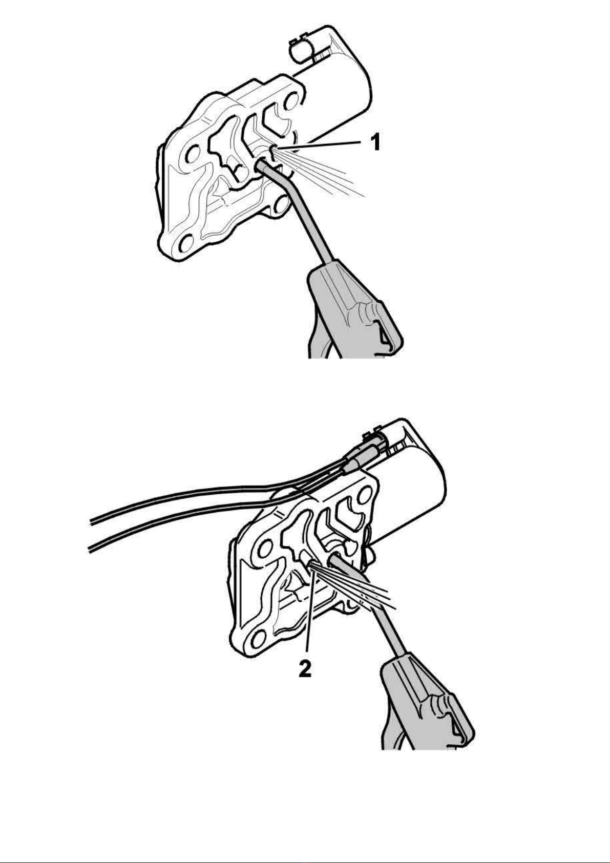
2005 Volvo XC70 L5-2.5L Turbo VIN 59 B5254T2 Copyright © 2011, ALLDATA 10.40 Page 3
gg
gggggggggggggggggggggg
Remove VVT solenoid from camshaft cover.
Blow through center hole with compressed air.
Air should emerge from inner hole (1) nearest coil.
Connect power to solenoid. Solenoid should click.
Blow through center hole with compressed air.
Air should emerge from outer hole (2).
If plunger is sticking or solenoid fails to operate electrically, the direction of flow will be unchanged from step 1.
VVT solenoid, cleaning
Page 77
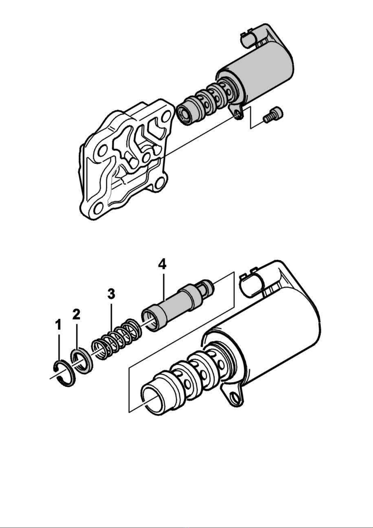
2005 Volvo XC70 L5-2.5L Turbo VIN 59 B5254T2 Copyright © 2011, ALLDATA 10.40 Page 4
gg
gggggggggggggggggggggg
Remove solenoid from aluminum housing.
Remove:
- snap ring (1)
- washer (2), spring (3) and plunger (4).
Inspect and clean all parts.
Blow out aluminum housing.
Oil parts with engine oil.
Reassemble solenoid.
Page 78

2005 Volvo XC70 L5-2.5L Turbo VIN 59 B5254T2 Copyright © 2011, ALLDATA 10.40 Page 5
gg
gggggggggggggggggggggg
Check operation as described in operations 1 and 2.
Reinstall solenoid in car using new seal.
Testing
Erase diagnostic trouble codes.
Test-drive car.
Check that no new diagnostic trouble codes are displayed.
If new codes are displayed, continue troubleshooting as per VIDA.
Page 79
2005 Volvo XC70 L5-2.5L Turbo VIN 59 B5254T2 Copyright © 2011, ALLDATA 10.40 Page 1
gg
gggggggggggggggggggggg
Compression Check: Testing and Inspection
Compression Test
Compression test
Special tools:
999 9689 COMPRESSION METER See: Tools and Equipment/999 9689 Compression Meter
115 8540 EXTENSION See: Tools and Equipment/115 8540 Extension
Ignition system
A check for cylinder leakage (also called "leak down") can be carried out instead of a compression test. Cylinder leakage test See: Testing and
Inspection/Cylinder Leakage Test
Caution! The ignition system operates at high ignition charges and produces dangerous voltages in both the low and high voltage circuits.
There is dangerous voltage throughout the entire ignition system including connectors etc.
Conditions
Note! The engine compression must always be checked with wide open throttle (WOT) and engine at operating temperature.
Preparations
Remove:
- the charge air pipe over the engine to improve accessibility.
- the upper timing belt cover.
- the cover over the ignition coils.
- the ignition coils.
Mark up and put to one side without disconnecting the connectors.
- the spark plugs.
Note! Separate the connector for the engine speed (RPM) sensor.
Page 80
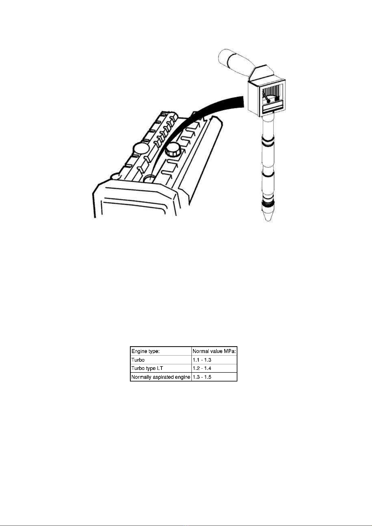
2005 Volvo XC70 L5-2.5L Turbo VIN 59 B5254T2 Copyright © 2011, ALLDATA 10.40 Page 2
gg
gggggggggggggggggggggg
Compression testing
Note! Compression testing should always be carried out at wide open throttle (WOT) and with the engine at operating temperature.
Diagnostic trouble codes (DTCs) will be stored because the engine speed (RPM) sensor and (where applicable) the camshaft position
(CMP) sensor have been disconnected.
Have an assistant hold the accelerator pedal (AP) depressed at wide open throttle (WOT) during the compression test.
The starter motor is activated with the ignition key.
The ignition must be switched off after each cylinder has been compression tested.
Note! It will no longer be possible to control the throttle if the ignition is on for longer than 2 minutes.The throttle function is controlled by
the control module.
Use compression meter 999 9689 COMPRESSION METER See: Tools and Equipment/999 9689 Compression Meter
with extension sleeve 115 8540 EXTENSION See: Tools and Equipment/115 8540 Extension.
Install
Install:
- the spark plugs.
Tighten to
- the ignition coils according to the earlier markings.
Tighten to
- the cover over the ignition coils.
- the upper timing belt cover.
- the disassembled connectors.
- charge air pipe.
Remove the seals.
Tighten the mountings and hose clamps.
25 Nm
10 Nm
.
.
Erase diagnostic trouble codes (DTCs) and check
Page 81
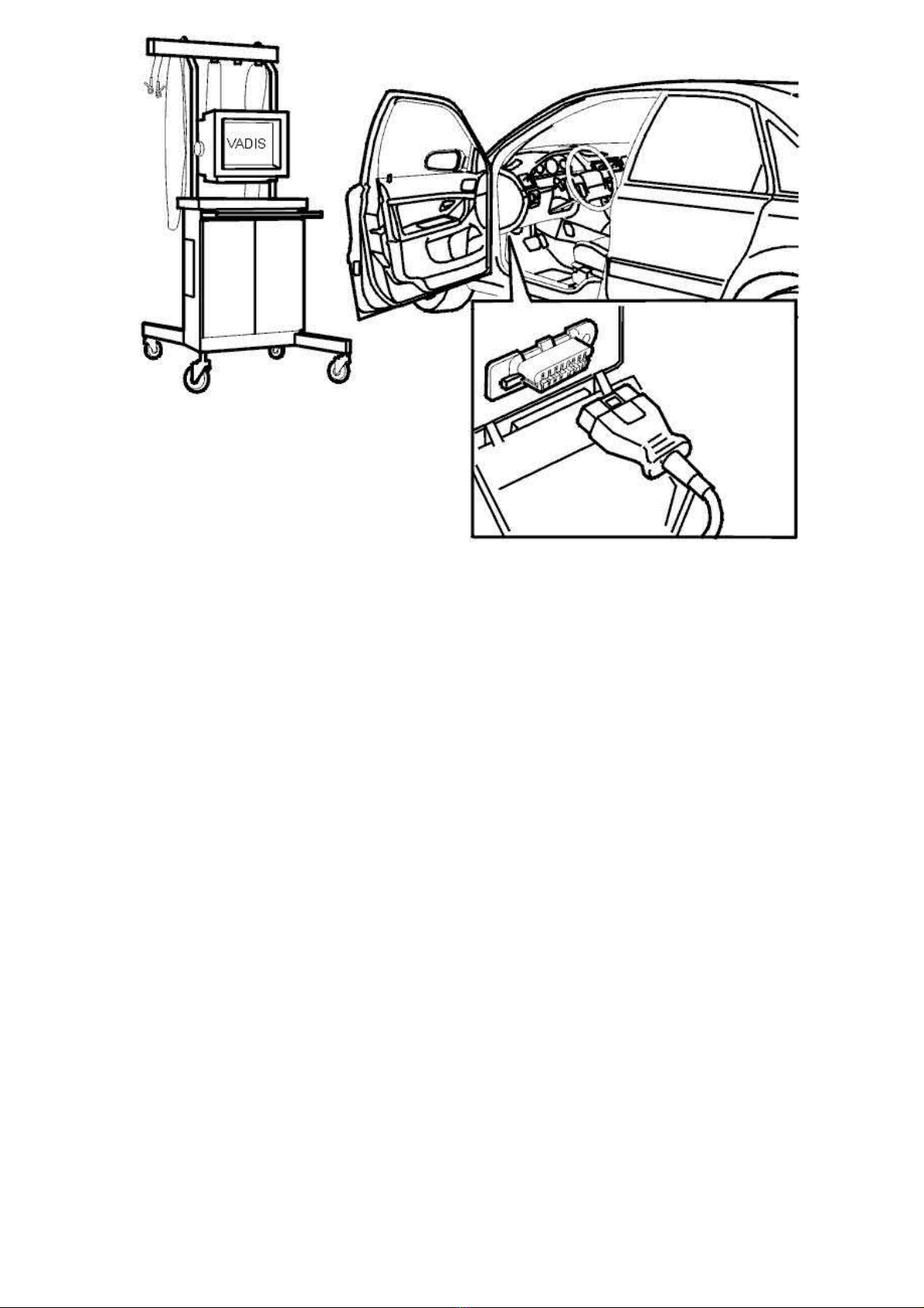
2005 Volvo XC70 L5-2.5L Turbo VIN 59 B5254T2 Copyright © 2011, ALLDATA 10.40 Page 3
gg
gggggggggggggggggggggg
Erase diagnostic trouble codes (DTCs):
Start the engine. Check that the engine is functioning normally.
Use VIDA vehicle communication to check which diagnostic trouble codes (DTCs) have been stored.
Erase the diagnostic trouble codes (DTCs).
Check the engine compartment. Wipe the engine compartment clean.
Page 82
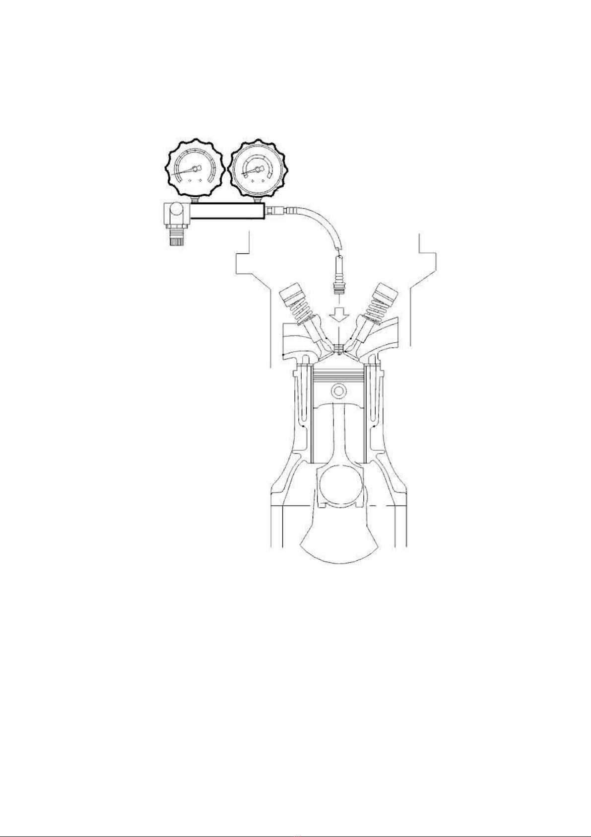
2005 Volvo XC70 L5-2.5L Turbo VIN 59 B5254T2 Copyright © 2011, ALLDATA 10.40 Page 1
gg
gggggggggggggggggggggg
Compression Check: Testing and Inspection
Cylinder Leakage Test
Cylinder leakage test
General method description
The cylinders can be checked for leakage as an alternative to a compression test
Using this method, the amount of leakage at the engine cylinders is measured and it is possible to locate the source of any leaks.
A similar check can be performed using a compression gauge by injecting oil in the cylinder. However, this can cause a build-up of coke!
The result will not always be decisive or precise.
In addition, the VIDA station or the Volvo System Tester (VST) must always be connected afterwards to erase any diagnostic trouble codes
(DTCs).
How is the cylinder checked for leakage?
- The engine should be run to operating temperature so that the thermostat is open
- The piston in the cylinder that is being checked must be set to top dead centre (TDC) at the compression phase
- A metered air pressure is connected to the relevant cylinder via an adapter that is secured in the spark plug / glow plug well
- A gauge is used to measure the size of the leakage from the cylinder.
This is a pressure sensor with a regulator and displays the size of the leak expressed as a percentage.
This allows the extent of any problem to be determined.
Fault-tracing
The source of a leak can be located by analyzing sound at the following points.
Page 83

2005 Volvo XC70 L5-2.5L Turbo VIN 59 B5254T2 Copyright © 2011, ALLDATA 10.40 Page 2
gg
gggggggggggggggggggggg
A mechanic's stethoscope or a rubber hose can be used as a listening device.
Note! There is leakage at the piston rings even on a perfect engine.This is the only place where a small leak is permissible.
Check
If a leak is detected that is assumed to come from the valve system, first check that the piston in the relevant cylinder is at top dead centre (TDC).
Then try to set the piston just prior to top dead centre (TDC) and redo the test.
When repeating the leak test on the same engine, there are usually variations in the results of the measurements.
This is due to changes in the engine coolant temperature (ECT) and the piston not reaching the same position as in the previous test, and is affected
by the amount of oil on the piston rings at the time.
Other information
Use: 951 2775 Cylinder leak tester
For D5244TX diesel engines, use: 999 7222 Adapter See: Tools and Equipment/999 7222 Adapter.
See: Tools and Equipment/951 2775 Cylinder Leak Tester.
Page 84
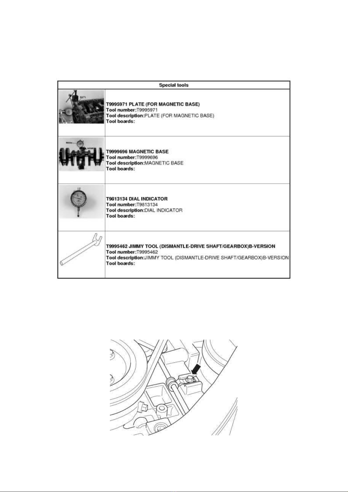
2005 Volvo XC70 L5-2.5L Turbo VIN 59 B5254T2 Copyright © 2011, ALLDATA 10.40 Page 1
gg
gggggggggggggggggggggg
Crankshaft: Service and Repair
Crankshaft Axial Play
Crankshaft axial play
Operation number:
Note! Some variation in the illustrations may occur, but the essential information is always correct.
21685-2
Removal
Note! Removal steps in this procedure may contain installation details.
Remove the right front wheel.
When installing Refer to: Installing wheels See: Maintenance/Wheels and Tires/Wheels/Service and Repair
Fold away the wheel arch liner and tie it up.
Remove the clamp screw on the fuel line. Move the clamp upward.
Torque:
M7, 17 Nm
Page 85
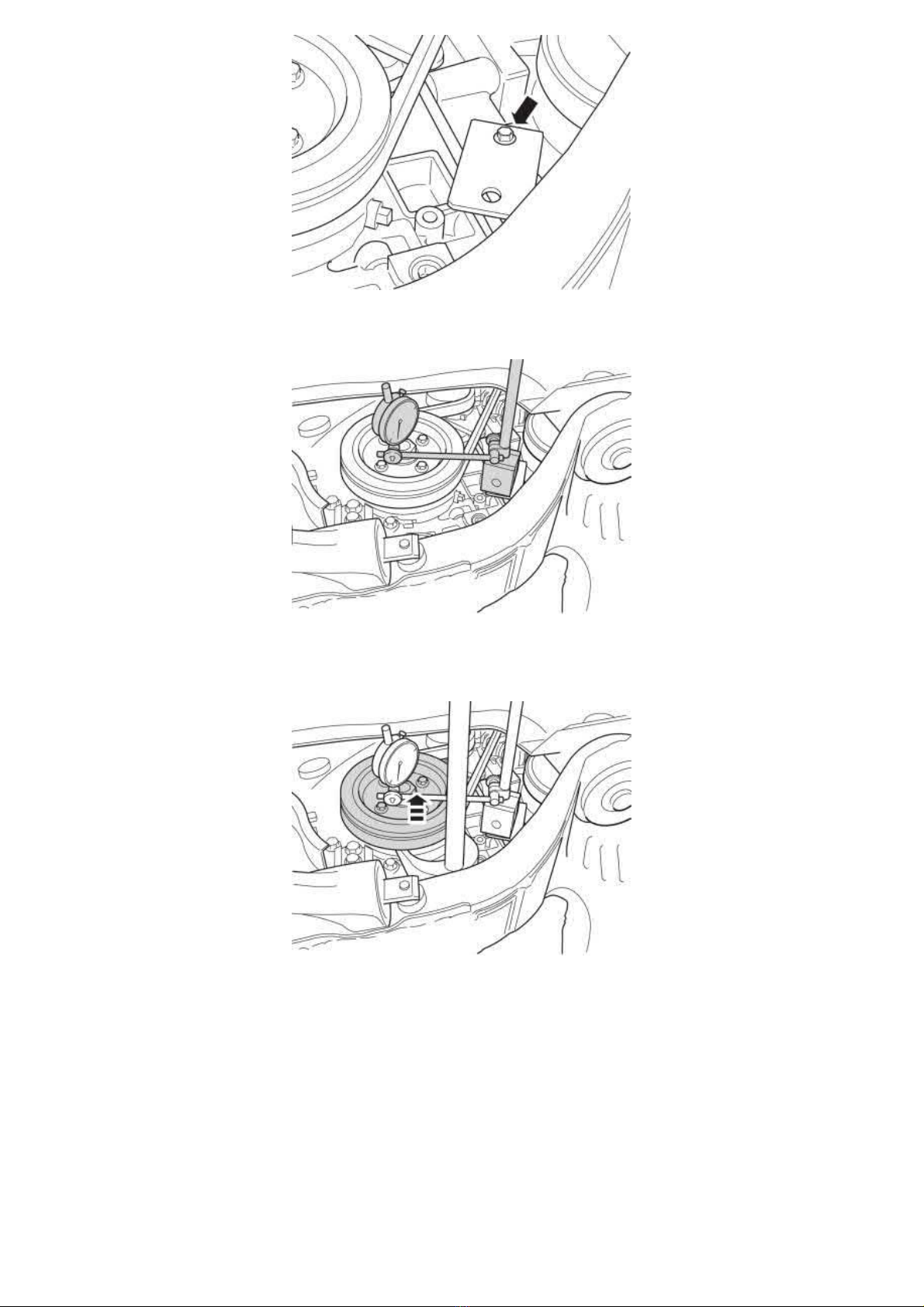
2005 Volvo XC70 L5-2.5L Turbo VIN 59 B5254T2 Copyright © 2011, ALLDATA 10.40 Page 2
gg
gggggggggggggggggggggg
999 5971 PLATE See: Tools and Equipment/999 5971 Plate
Torque:
M7, 17 Nm
999 9696 MAGNETIC BASE See: Tools and Equipment/999 9696 Magnetic Base
981 3134 DIAL INDICATOR See: Tools and Equipment/981 3134 Dial Indicator
Measure the crankshaft nut or the oscillation damper's inner ring.
Pry out the crankshaft.999 5462 Jimmy tool See: Tools and Equipment/999 5462 Jimmy Tool
Zero the dial indicator.
Page 86
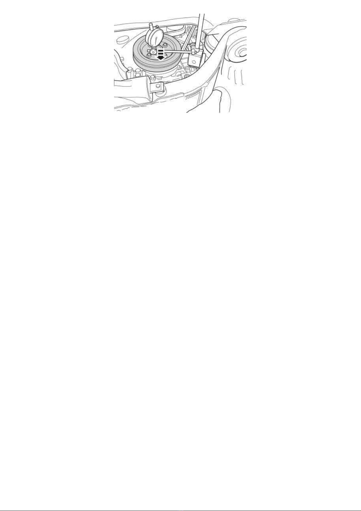
2005 Volvo XC70 L5-2.5L Turbo VIN 59 B5254T2 Copyright © 2011, ALLDATA 10.40 Page 3
gg
gggggggggggggggggggggg
Push in the crankshaft. Use both hands and press hard. In the event of problems moving the crankshaft toward the gearbox, run the engine warm
and use a crowbar placed between the oscillation damper and the member. Use protective blocks.
Read the dial indicator. Max permitted play 0.25 mm.
Repeat the procedure several times.
Installation
Remove the test equipment.
To install, reverse the removal procedure
Page 87
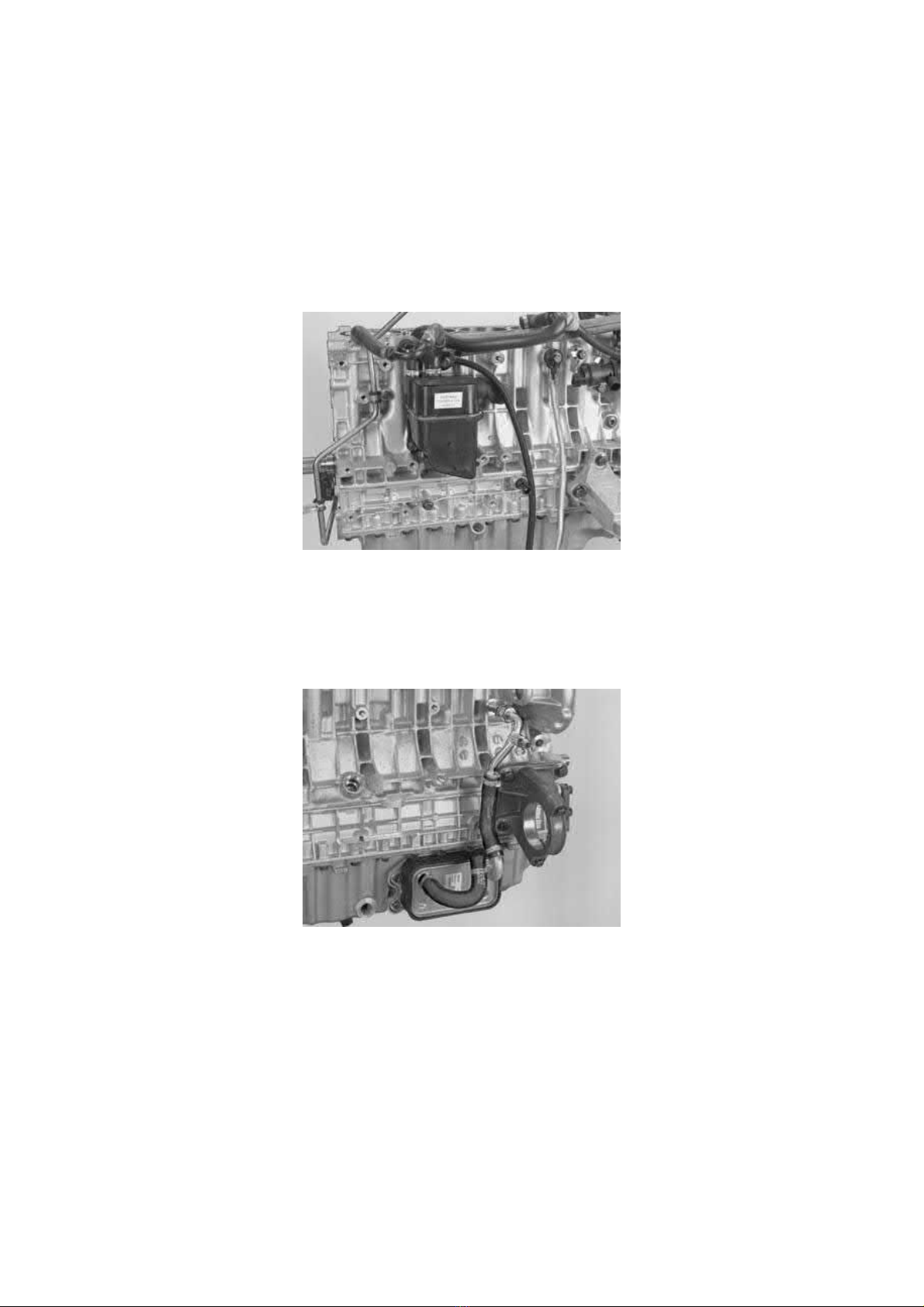
2005 Volvo XC70 L5-2.5L Turbo VIN 59 B5254T2 Copyright © 2011, ALLDATA 10.40 Page 1
gg
gggggggggggggggggggggg
Crankshaft: Service and Repair
Crank Mechanism, Dismantling
Crankshaft assembly, disassembling
Special tools:
999 5458 KEY See: Tools and Equipment/999 5458 Key
999 5679 Oil filter spanner See: Tools and Equipment/999 5679 Oil Filter Spanner
Note! As the illustrations in this service information are used for different model years and / or models, some variation may occur.
However, the essential information in the illustrations is always correct.
Preparation
Remove:
- the oil trap
- the knock sensors (KS)
- the front engine mounting
- the oil pressure switch
- Evaporative emission system (EVAP) valve with hoses.
Remove:
- the bearing retainer for the right drive shaft
- the oil cooler and the rubber seals including hoses and pipes.
Removing the oil filter and oil pan
Page 88
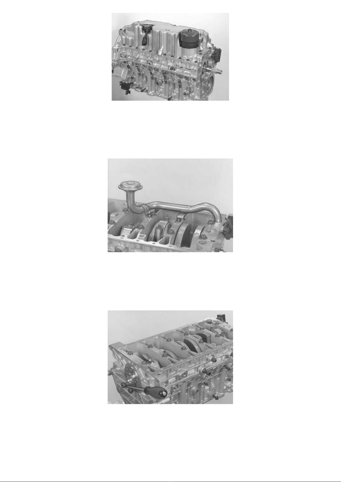
2005 Volvo XC70 L5-2.5L Turbo VIN 59 B5254T2 Copyright © 2011, ALLDATA 10.40 Page 2
gg
gggggggggggggggggggggg
Remove:
- the oil filter. Use tool 999 5679 Oil filter spanner See: Tools and Equipment/999 5679 Oil Filter Spanner
- the screws holding the oil pump to the intermediate section.
Carefully tap the side of the oil pan with a rubber mallet.
Lift out the oil pan.
Removing the suction pipe from the oil pump
Remove:
- the O rings for the oil ducts
- the retaining screws holding the suction pump to the intermediate section. Work / lift out the suction pipe
- the O-ring for the suction pipe.
Check the pipe and the strainer. Check for cracks and impurities.
Checking markings
Install the two old screws for the flywheel and carrier plate at the rear edge of the crankshaft.
Turn the crankshaft so the piston in cylinder 1 is at bottom dead center (BDC).
Check that there are markings on the cap and connecting rods. Check which way the markings are positioned (exhaust and intake side). Make a
note of this.
If necessary mark with a center punch or a number punch. See Crank mechanism, assembling, B5244T5, B5254T2 See: Crank Mechanism,
Assembling.
New connecting rod
Page 89
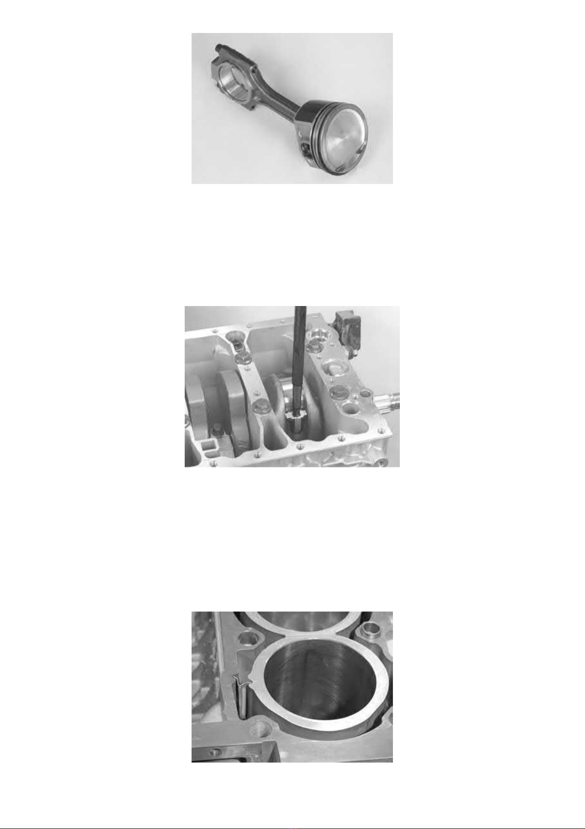
2005 Volvo XC70 L5-2.5L Turbo VIN 59 B5254T2 Copyright © 2011, ALLDATA 10.40 Page 3
gg
gggggggggggggggggggggg
A new connecting rod has been introduced on certain engines.
The mating surface between the cap and the connecting rod is not machined. It is aligned through a dedicated fracture surface.
Caution! If the cap is turned the wrong way and tightened, the structure of the fracture surface will be damaged and the connecting rod
must then be discarded.
Note! Blow the fracture surface clean using compressed air before installing the cap.
Removing the pistons from the cylinder block
Caution! The bearing covers are not interchangeable. Also note the position of the bearing caps in relation to the rotation of the crankshaft
.
Remove the screws for the connecting rod cover.
Lift off the cover. Ensure that the bearing cover comes with it.
Install tool in the connecting rod. Press out the connecting rod and piston.
Hold by hand so that the piston does not fall to the floor. Ensure that the bearing cover comes with it.
Place the piston and connecting rod in such a way that they will be reinstalled in the correct cylinder.
Continue with cylinders 2, 3, 4 and 5 as above.
Check
Check that the coolant guide is in place. Secure if necessary.
Page 90
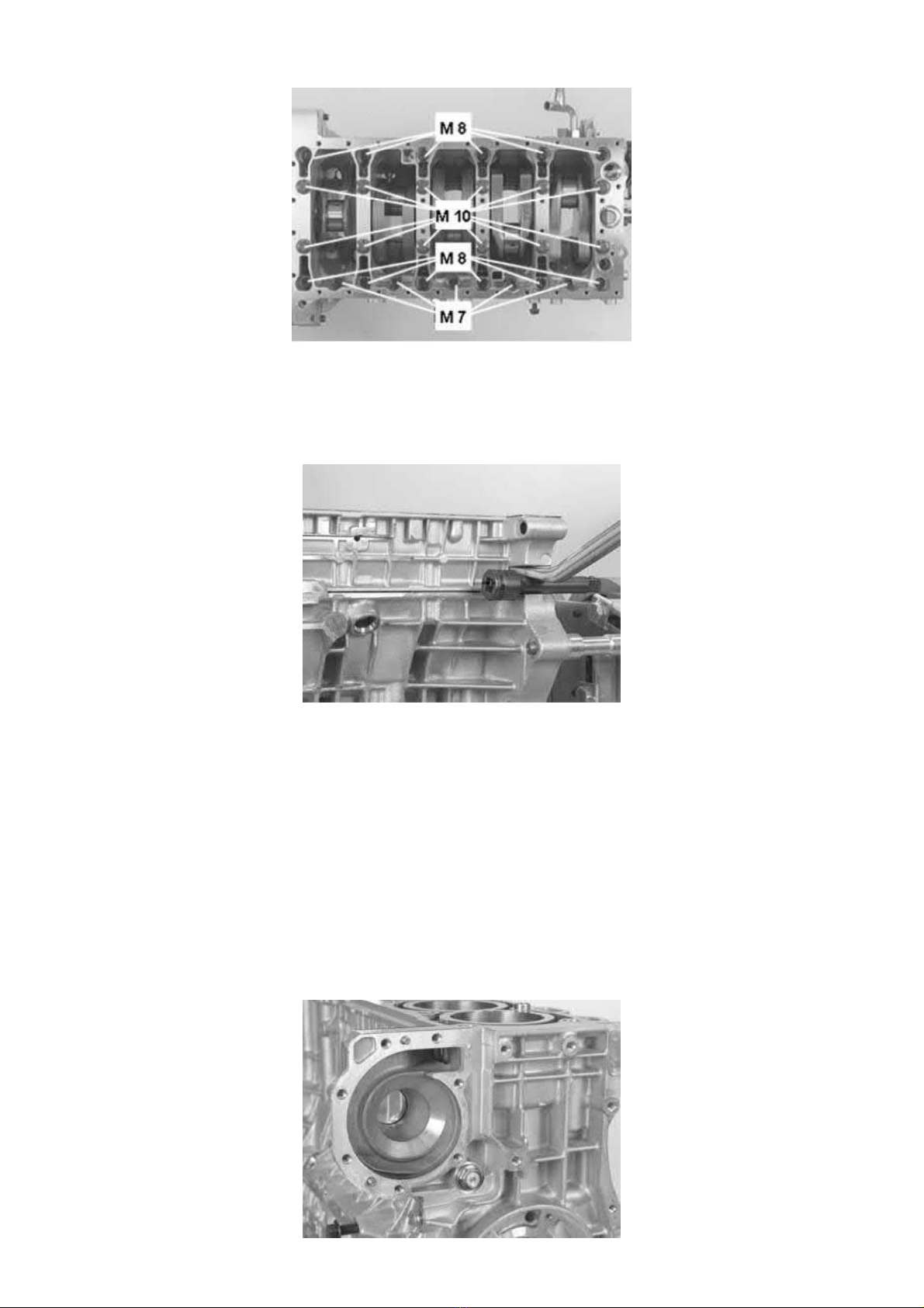
2005 Volvo XC70 L5-2.5L Turbo VIN 59 B5254T2 Copyright © 2011, ALLDATA 10.40 Page 4
gg
gggggggggggggggggggggg
Removing the screwed joint from the intermediate section
First remove the M7 screws from the intermediate section.
Then remove the M8 screws. Start at the outer edges and work alternately towards the center.
Remove the M10 screws in the same way.
Separating the intermediate section from the cylinder block
Caution! The bearing covers are not interchangeable.Also note the position of the upper half of the axial bearing for the direction of
rotation of the crankshaft.The crankshaft must not rotate.
Carefully pry the intermediate section from the cylinder block so that there is a gap of approximately
Then carefully tap off (on the exhaust side) the intermediate section with a rubber mallet.
Lift out the intermediate section. Ensure that the bearing covers for the intermediate section come with it.
Note! The bearing covers for the different bearing recesses are not interchangeable.
Ensure that the screws for the flywheel and carrier plate, which were installed earlier, are properly tightened. Lift them and the front of the
crankshaft.
Carefully lift the crankshaft straight up.
Remove the remaining bearing covers.
Removing the piston cooling valve and nozzles
6-8 mm
.
Page 91
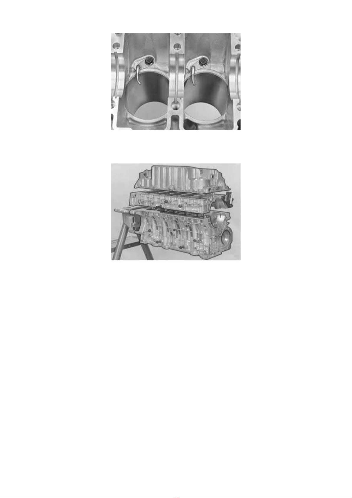
2005 Volvo XC70 L5-2.5L Turbo VIN 59 B5254T2 Copyright © 2011, ALLDATA 10.40 Page 5
gg
gggggggggggggggggggggg
Remove the piston cooling valve at the front of the engine.
Remove the piston cooling nozzles.
Cleaning
Warning! A fume hood or extractor must be used when using gasket solution.
Clean the gasket surfaces on the cylinder block, intermediate section and oil pan.
Use a razor blade or a gasket scraper and / or gasket solvent (
P/N 116 1440
).
Page 92
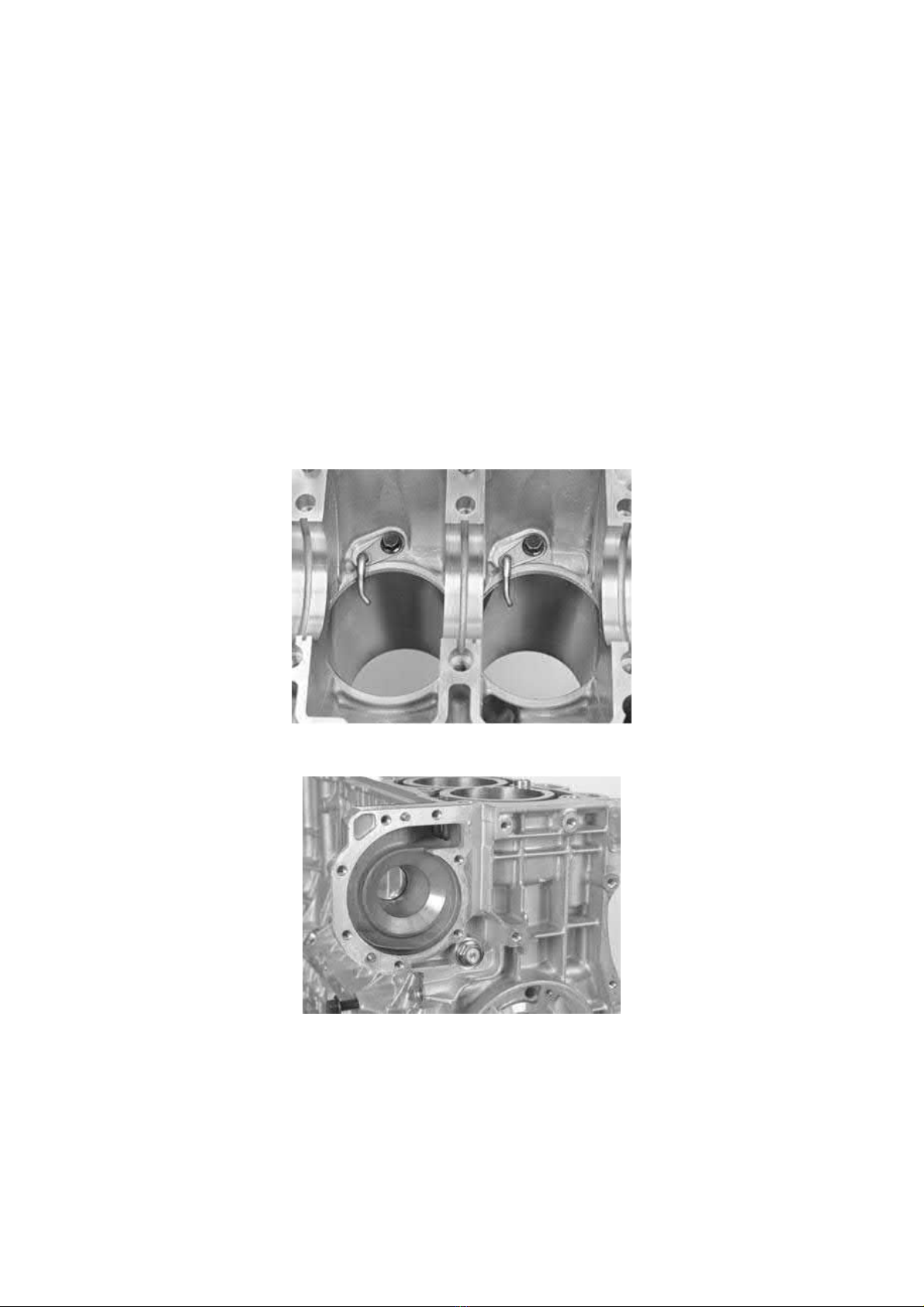
2005 Volvo XC70 L5-2.5L Turbo VIN 59 B5254T2 Copyright © 2011, ALLDATA 10.40 Page 1
gg
gggggggggggggggggggggg
Crankshaft: Service and Repair
Crank Mechanism, Assembling
Crank mechanism, assembling
Special tools:
951 2767 Roller See: Tools and Equipment/951 2767 Roller
999 1801 STANDARD SHAFT See: Tools and Equipment/999 1801 Standard Shaft
999 5676 Drift replaced by 9997174 See: Tools and Equipment/999 5676 Drift Replaced By 9997174
999 5746 Holder See: Tools and Equipment/999 5746 Holder
Note! The illustrations in this service information are used for different model years and/or models. Some variation may occur. However,
the essential information in the illustrations is always correct.
Note! For tightening torques not in the text, see Tightening torque See: Specifications/Tightening Torque.
Cleaning
Ensure that the all components are
Blow clean the oil ducts in the block, intermediate section and sump.
Installing the piston cooling valve and nozzles
Install the piston cooling nozzles. Tighten the screws.
completely
clean.
Install the piston cooling valve. Use a seal washer. Tighten. See Tightening torque See: Specifications/Tightening Torque.
Classification of main bearings
Page 93
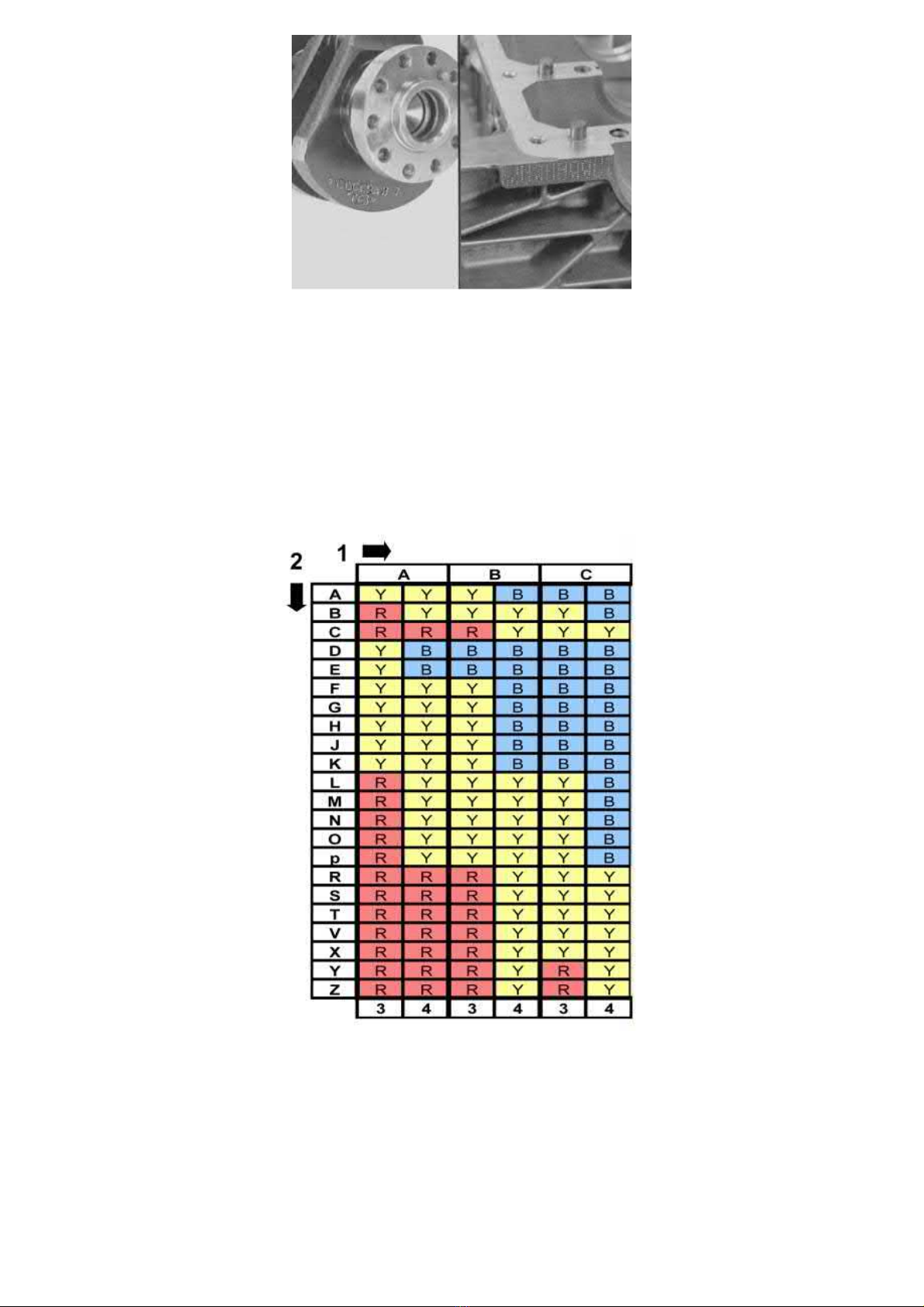
2005 Volvo XC70 L5-2.5L Turbo VIN 59 B5254T2 Copyright © 2011, ALLDATA 10.40 Page 2
gg
gggggggggggggggggggggg
Wipe clean the bearing recesses in the block and the intermediate section.
Check that the components are clean and undamaged.
Check the classification of the block and crankshaft.
The classification marking is at the rear edge of the block and the crankshaft. The classification is read from digit 1 to 7. The first letter after digit 1
is the classification of main bearing 1. The bearing recesses are numbered starting at the front of the engine.
Selecting bearings
Note! Always use new bearings.
Bearing halves with grooves are always installed in the engine block.
Install the main bearings in the cylinder block and the intermediate section. See the table. The axial bearing is positioned at bearing recess 5
1. Classification cylinder block
2. Classification crankshaft
3. cylinder block
4. Intermediate section
Example. The marking on the block at bearing position 1 is B. The marking on the crankshaft at the corresponding bearing position is C. This gives
a red marked bearing in the block and a yellow marked bearing in the intermediate section.
Note! The thickest of the bearing halves shall always be installed in the intermediate section. This is to keep the centre line as straight as
possible.
Applying liquid gasket
Page 94
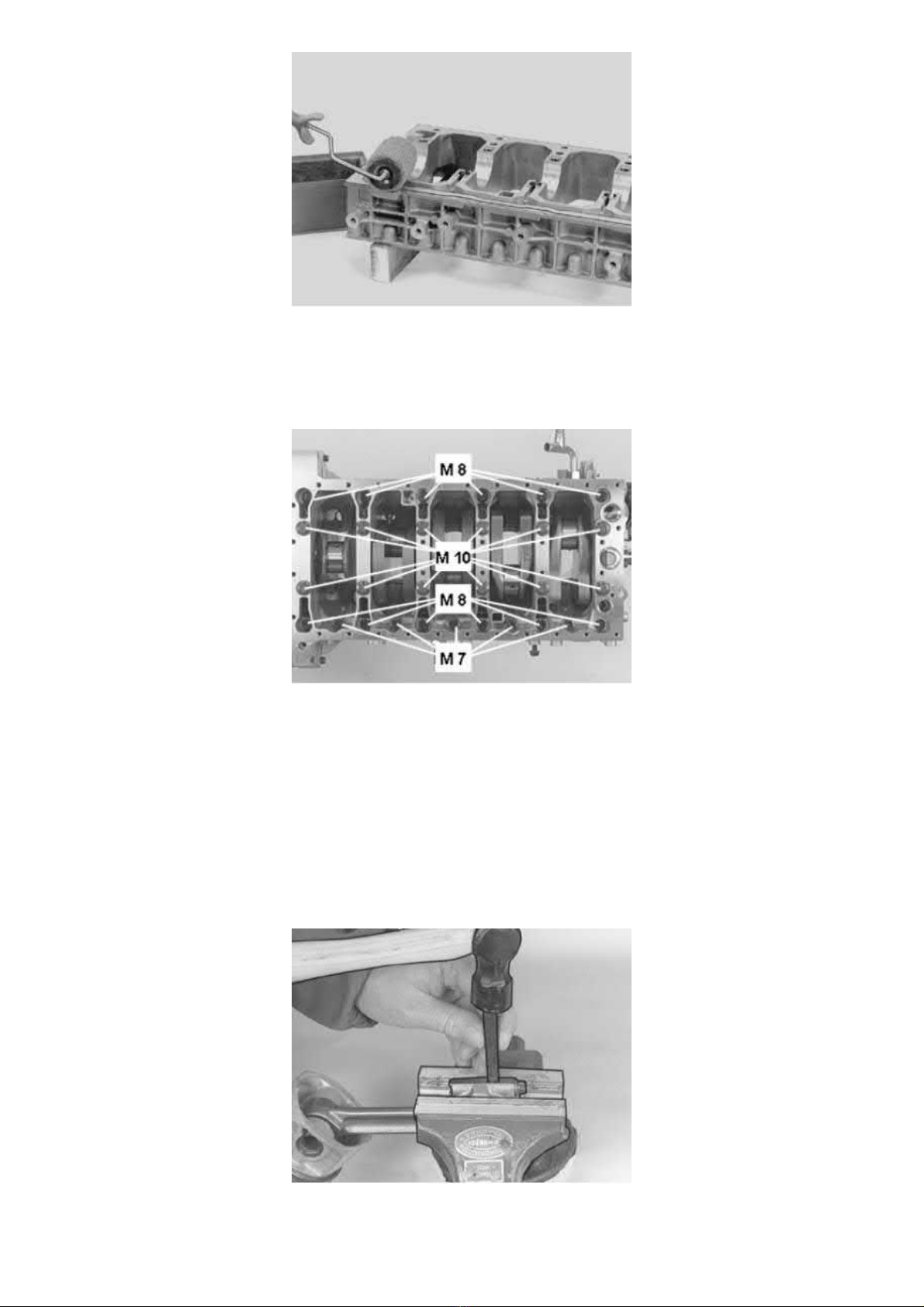
2005 Volvo XC70 L5-2.5L Turbo VIN 59 B5254T2 Copyright © 2011, ALLDATA 10.40 Page 3
gg
gggggggggggggggggggggg
Wipe the surfaces dry. Apply liquid gasket 11 61 059 to the intermediate section.
The surface must be completely covered without any excess. Use roller 951 2767 Roller See: Tools and Equipment/951 2767 Roller. Thoroughly
lubricate all the bearing shells and the thrust bearing's surface.
Tightening the intermediate section
Install the two old screws for the flywheel and carrier plate at the rear edge of the crankshaft. Lift these and the front of the crankshaft.
Carefully position the crankshaft in the block. The crankshaft must
the intermediate section. Lubricate and install all the screws.
Note! Use new M10 bolts.
Caution! The M8-bolts on the exhaust side have two lengths.
Install the intermediate section and the screws on the exhaust side at bearing recesses 2 and 5.
Pull down the intermediate section. Tighten the screws. See Tightening torque See: Specifications/Tightening Torque.
Marking the connecting rod (where applicable)
be turned before the intermediate section has been torque tightened. Position
not
Assemble the connecting rod. Check that the cover is facing the correct direction. Tighten to
Secure the large end of the connecting rod in a vice with soft jaws (copper or aluminium). Mark both halves with the cylinder number. Use a centre
punch or number punch.
20 Nm
.
Page 95
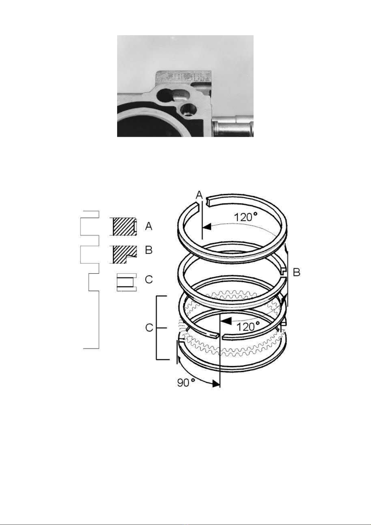
2005 Volvo XC70 L5-2.5L Turbo VIN 59 B5254T2 Copyright © 2011, ALLDATA 10.40 Page 4
gg
gggggggggggggggggggggg
Selecting piston
For every cylinder there is a classification letter stamped (C, D, E) on the top of the engine block.
First letter after the digit 1 corresponds to the classification of the cylinder bore in cylinder 1 and is then followed by cyl. 2, 3, 4, 5.
Cylinder selection is determined by the classification of the cylinder bore. For example: Cylinder class D must have pistons marked D etc.
Installing piston rings
Caution! Make sure that the piston rings are not stuck and that they turn easily.
Note! Incorrect positioning may result in higher oil consumption.
Use piston ring pliers. Turn the piston rings so that the openings are offset as illustrated.
A=Compression ring. The text on the piston ring must be upwards.
B=Scraper ring. Chamfered edge must face downwards.
C=Oil ring. Three sections, identical on all sides. First install the expander ring (C), then the two other rings over the expander ring.
Assembling pistons and connecting rods
Page 96
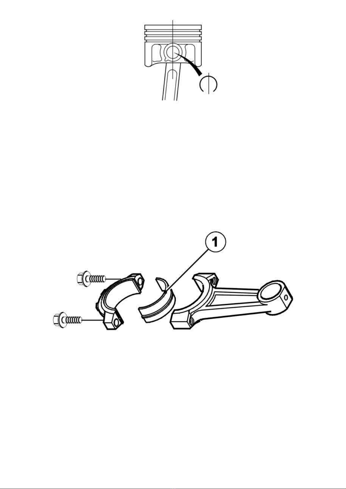
2005 Volvo XC70 L5-2.5L Turbo VIN 59 B5254T2 Copyright © 2011, ALLDATA 10.40 Page 5
gg
gggggggggggggggggggggg
Warning! The lock ring can easily fly off. Wear protective goggles
There is an arrow marking on the upper side of the cylinder. This must be turned forwards in the cylinder block.
The connecting rods are symmetrical and can be turned freely. Marked rods however must be turned in the same direction.
Assemble the connecting rod and piston with the piston pin. Check that the classification and any numbering for each cylinder/piston diameter and
connecting rod correspond.
Install both the snap rings on the piston pin. Check that the snap rings are positioned correctly in the piston. The opening must be vertical.
Wipe clean around the bearing recess in the connecting rod and the cap.
Installing the main bearing shells
Always use new bearings.
Check these for colour marking. The bearing shell with a black colour coding on the side (1) must be installed in the connecting rod.
Installing the pistons in the cylinder bores
Page 97
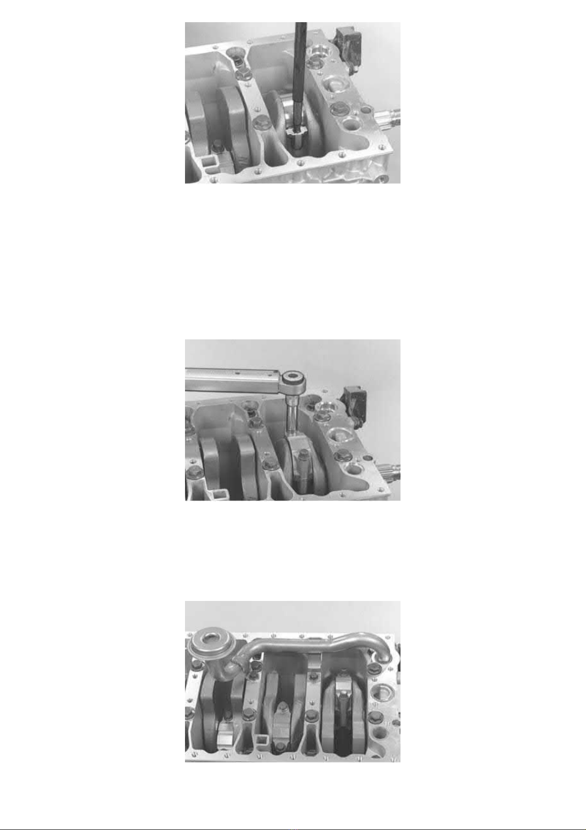
2005 Volvo XC70 L5-2.5L Turbo VIN 59 B5254T2 Copyright © 2011, ALLDATA 10.40 Page 6
gg
gggggggggggggggggggggg
Note! The arrow (top of the piston) must point forwards, and make sure that the classification matches.
Use a cylinder ring compressor.
Lubricate the cylinder bore, the pistons and the bearing shells.
Turn the crankshaft so that the connecting rod pin is at bottom dead center (BDC) for the cylinder the piston is to be inserted in.
Ensure that the engine is in a position where the cylinder bore forms as vertical a line as possible.
Carefully press or tap the piston down (using the shaft of a hammer or similar). When the piston releases from the piston ring compressor, turn the
engine
Install tool 999 5746 Holder See: Tools and Equipment/999 5746 Holder in the connecting rod. Pull the connecting rod until it secures against the
big end journals.
in the stand.
180°
Tightening the
Note! The crankshaft must not be rotated before the connecting rod cap has been tightened.
Install the cap. Check that any markings correspond.
Lubricate and install new screws. Tighten the screws. See Tightening torque See: Specifications/Tightening Torque.
Check that the connecting rod can be moved sideways.
Installing the oil pump suction pipe
connecting rod cover
Install a new seal ring on the suction line.
Carefully press the suction pipe down into the intermediate section. Check that the sealing ring is correctly positioned.
Page 98
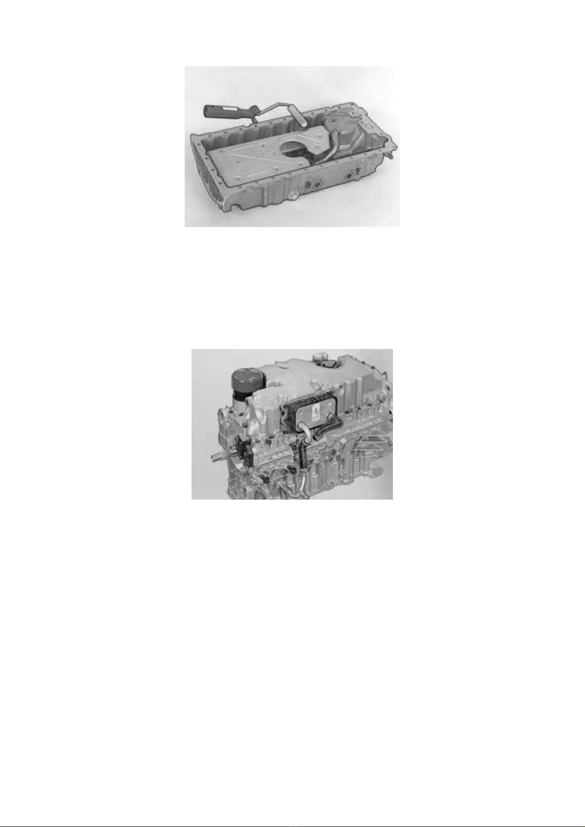
2005 Volvo XC70 L5-2.5L Turbo VIN 59 B5254T2 Copyright © 2011, ALLDATA 10.40 Page 7
gg
gggggggggggggggggggggg
Tighten the screws. Install new sealing rings for the oil ducts to the sump.
Installing the sump
Caution! Check that the rear edge of the oil sump is in line with the rear edge of the engine block. Permitted tolerance± 0.025 mm. Use a
steel ruler and feeler gauge.
Wipe the surfaces dry.
Apply liquid gasket 11 61 059 on the oil sump. Use roller 951 2767 Roller See: Tools and Equipment/951 2767 Roller. The surface must be
completely covered without any excess. Install the oil sump and install all bolts.
Tighten the screws. Start with the rear edge of the sump and work alternately forwards.
Installing the oil cooler
Install:
- new sealing rings in the oil pan
- the oil cooler. Tighten the screws
- the oil filter.
Cleaning
Page 99
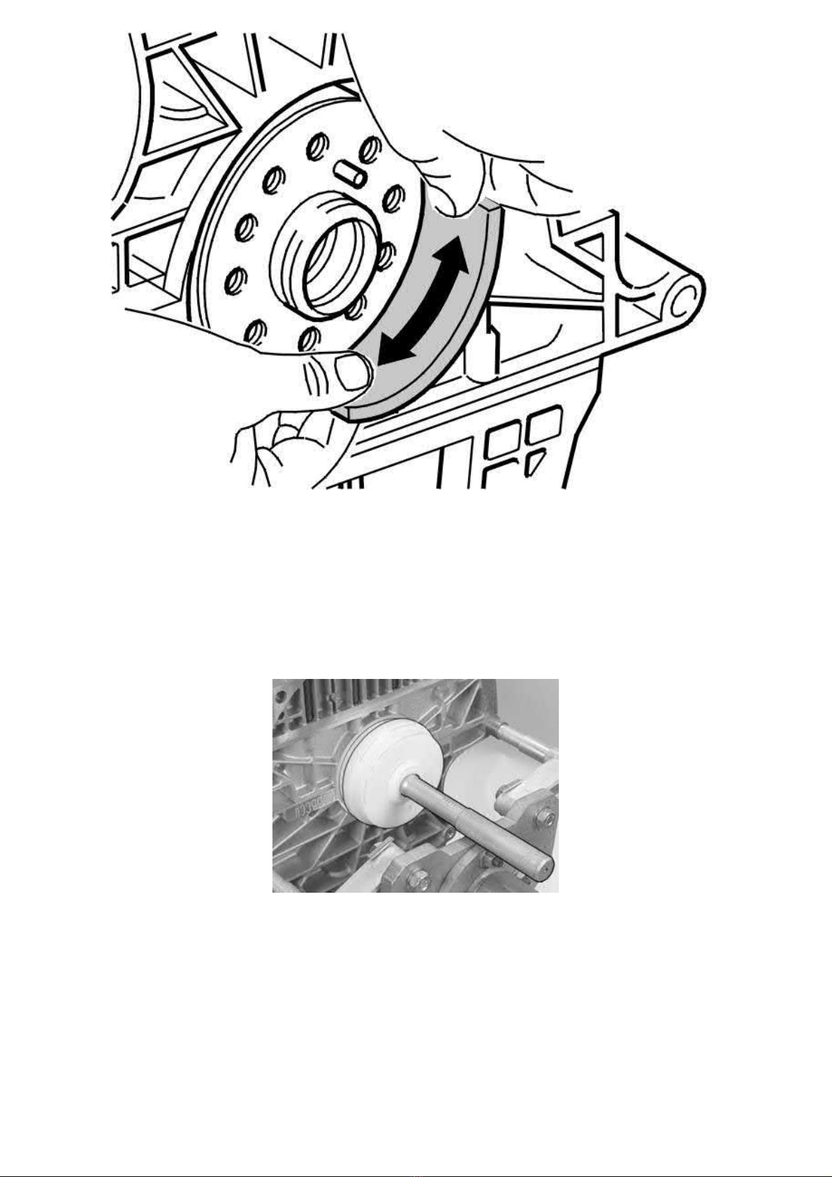
2005 Volvo XC70 L5-2.5L Turbo VIN 59 B5254T2 Copyright © 2011, ALLDATA 10.40 Page 8
gg
gggggggggggggggggggggg
Caution! Cleaning shall always be done in the direction around the flange, not in and out. No grinding tools or similar may be used. It is
extremely important that there is no remaining thread sealant or other dirt, as this may cause leakage.
Note! Use emery cloth 9511024 to clean the crankshaft end.
If necessary, wash off the oil on the rear cylinder block surface. Blow clean using compressed air.
When cleaning, work around the shaft journal, not in and out. It is essential that any residue from the emery cloth and any other contaminants are
completely removed before the new sealing ring is installed.
Installing the rear crankshaft seal
Use standard handle 999 1801 STANDARD SHAFT See: Tools and Equipment/999 1801 Standard Shaft and drift 999 5676 Drift replaced by
9997174 See: Tools and Equipment/999 5676 Drift Replaced By 9997174.
Lubricate the drift face. Thread the seal onto the drift. Tap in the seal until the drift bottoms against the block.
Page 100
2005 Volvo XC70 L5-2.5L Turbo VIN 59 B5254T2 Copyright © 2011, ALLDATA 10.40 Page 1
gg
gggggggggggggggggggggg
Engine Block Heater: Service and Repair
Passenger Compartment Connector Socket
Passenger compartment connector socket
 Loading...