

Page 1

Standard STD 420-0003
Volvo Group
Established
July 2006
Version 1 Page
1(11)
TEST METHOD
Fogging
Organic materials
Orientation
As to its technical content, this standard conforms to ISO 6452:2000.
This standard replaces Volvo standard STD 1027,2711 and Ren ault standard D45 1727.
Contents
1 Scope
2 Principle
3 Materials
3.1 Thermal-transfer fluid
3.2 Glass-cleaning detergent
3.3 Diisodecyl phthalate (DIDP)
3.4 Test fluid
4 Apparatus
4.1 General
4.2 Thermostatically controlled bath
4.3 Cooling plates
4.4 Flat-bottomed beakers
4.5 Metal rings
4.6 Sealing rings
4.7 Float-glass plates
4.8 Filter paper
4.9 Aluminium foil
4.10 Reflector meter
4.11 Spacer
4.12 Dishwasher
4.13 Balance
4.14 Glass plate rack
4.15 Phosphorpentoxide and silica gel
4.16 Stamping apparatus
4.17 Gloves
4.18 Desiccator with suitable drying material
4.19 Lintless paper for industrial cleaning
5 Test pieces
6 Test procedure
6.1 Method F (reflectometric method, evaluation of fogging using a glossmeter)
6.2 Method G (gravimetric method, evaluation of fogging using a balance)
7 Report
8 Temperature options
Page 2

Standard STD 420-0003
Volvo Group
Version
1
Page
2
1 Scope
This standard specifies a test method which is intended to determine the fogging characteristics of materials that
are used in the interior of motor vehicles.
The method may also be applicable to fluid, pasty, powdered or solid raw materials which ar e the basis for such
materials or from which the materials are manufactured. The method may also be applicable to other materials and
finished products.
The procedure is applicable to the measurement of fog condensate on glass surfaces within the limits of the test
conditions. This test will not measure or cannot measure reflectometer values accurately in those cases where:
- the surface tension of the condensate is low, resulting in early coalescing into a thin transpa re nt film;
- the condensate is present in such a large quantity that the droplets coalesce and form a heavy/clear film
(this heavy film gives false reading). In these cases, the gravimetric method is preferred.
2 Principle
A test piece is heated in a glass beaker. Any volatile constituents are condensed on either a cooled glass plate or a
disc of cooled aluminium foil.
Method F: The fogging value F is the ratio, expressed in per cent, of gloss before and after the fogging test. The
gloss is measured with a glossmeter with a 60° measuring angle.
Method G: The fogging value G is the mass of the condensation on the aluminium foil, i.e. it is the difference,
expressed in mg, between the masses of the aluminium foil before and after testing.
3 Materials
3.1 Thermal-transfer fluid, for the thermostatically controlled bath. The fluid shall be temperature-stable and
preferably water-soluble for easier cleaning. A suitable fluid is a modified polyhydric aliphatic alcohol.
A fluid of this type is marketed by BASF under the brand Heizenbadfluessigkeit.
3.2 Glass-cleaning detergent, of non-alkaline type (alkaline washing-up detergent corrodes the glass and thus
affects the result).
3.3 Diisodecyl phthalate (DIDP), available from the stated source.
Reference liquid DIDP shall be obtained from:
The Swedish National Testing and Research Institute (SP)
Materials Technology
P.O. Box 857
SE-501 15 BORÅS
SWEDEN
Fax: +46 33 16 53 16
E-mail:
It is permissible to buy DIDP from other suppliers than the Swedish National Testing and Research Institute (SP)
but the supplier must then quality assure his testing procedure by buying DIDP from the Swedish National Testing
and Research Institute (SP) and perform acceptence tests in accordance with sections 6.1.3 and 6.2.3. In order to
comply with the requirements, the test results must be within the specified tolerances of ISO 6452.
3.4 Test fluid for checking the cleanliness of the glass plate shall consist of a methanol-water mixture containing
27,1 % of methanol (PA quality) and 72,9 % of distilled water by volume and having a surface tension of 46 mN/m
calculated according to Fowkes Theory. About 1 g of a soluble red dye (e.g. fuchsin) can be added to 1 litre of the
test fluid for easier detection.
Page 3

Standard STD 420-0003
Volvo Group
Version
1
Page
3
4 Apparatus
4.1 General
The equipment shall comply with the dimensional requirements specified in ISO 6452. Alternative equipments are
permitted provided it has been ascertained that they give the same result as equipment complying with ISO 6452.
Evaluation of alternative equipment shall be made by testing, and it shall be possible to give an account of the
result in accordance with sections 6.1.3 and 6.2.3. In order to comply with the requirements, the test results must
be within the specified tolerances.
4.2 Thermostatically controlled bath, designed to operate up to 130 °C. Safety devices shall be fitted to prevent
overheating. The circulation system, the bath capacity and the heating system shall be such that the temperature
can be kept constant to within ± 0,5 °C throughout the bath.
Note 1: It is very important to maintain a stable temperature, as tests have shown that even as slight a difference
as 0,5 °C does show in the test results.
The bath shall be designed so that, after placing the beakers in the bath, the temperature does not drop more than 5 °C,
and the test temperature is regained after no more than 10 min. The minimum distance between the beakers and
the walls shall be 30 mm and between the bottom of the bath and the beakers 60 mm.
The bath shall be equipped with a device indicating the distance between the bath fluid and the lower surface of the
glass plate. This distance shall be 60 ± 2 mm.
Note 2: Some heaters/circulators have a centrifugal pump in the bottom pumping the liquid at high speed around
the bath. The beakers will have the liquid passing them at different speeds and this will cause different
temperatures in the different beakers.
4.3 Cooling plates, designed to be placed on the glass plates to keep them cool. The cooling plates shall be
hollow and made of corrosion-resistant metal, with the side facing the glass plate made of aluminium. They shall
have two cooling-water connections located so that the cooling water flows throug h the whole of the interior of the
plate. The surface in contact with the glass plate shall be flat. The mass of a cooling plate filled with water shall be
at least 1 kg, to overcome the buoyancy of the beaker in the bath. The whole of the weight of the cooling plate shall
rest on the beaker. A separate cooling plate shall be used for each beaker.
The cooling plates and the associated water thermostat shall be designed so that the mean water temperature is
21 °C and the difference in temperature between the inlet and outlet does not exceed 1 °C.
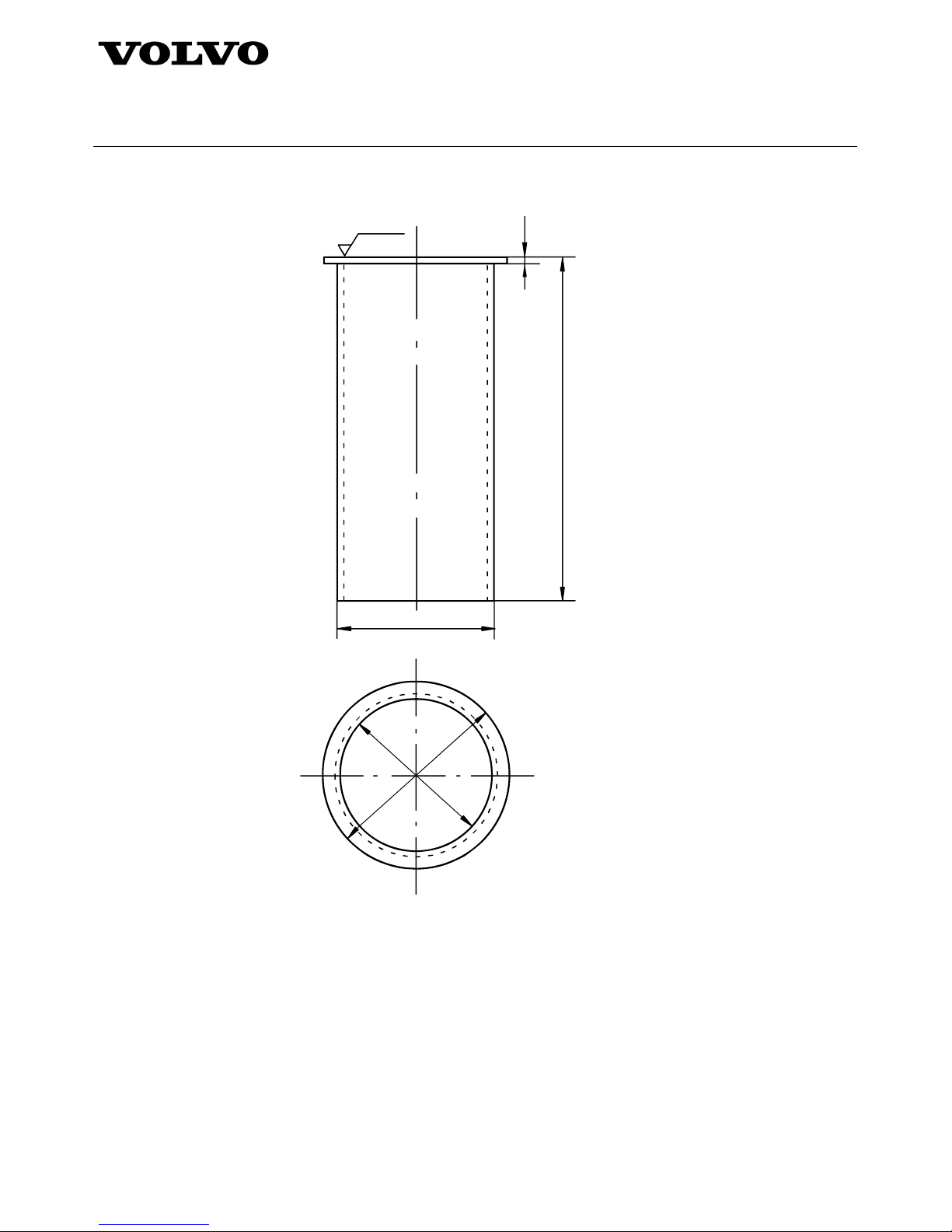
4.4 Flat-bottomed beakers, of heat-resistant glass, minimum mass 450 g, with the dimensions shown in Figure 1.
4.5 Metal rings, external diameter 80 mm, internal diameter 74 mm, height 10 mm and mass 55 ± 1 g, made of
corrosion-protected steel, to keep the test pieces flat.
4.6 Sealing rings, of fluoro-rubber or silicone rubber with L-shaped or circular cross-section, inner diameter 9095 mm, thickness 2-4 mm and hardness 50-70 IRHD.
4.7 Float-glass plates, of residential or windshield window quality for condensation of the fogging, thickness
3 ± 0,2 mm, either square with minimum dimensions of 110 x 110 mm or circular with a diameter of 103 mm. The
reflectometer values of all the plates used shall be the same to within ± 2 % units. The tin and non-tin surfaces of
the plates shall be identified.
NOTE - The tin and non-tin surfaces of the glass plates can be identified by viewing the surfaces in a darkened
room under UV light at 254 nm wavelength. The tin surface will fluoresce when exposed to the UV light.
4.8 Filter paper, with a diameter of 110 mm and a mass per unit surface area of 90 g/m
2
.
Page 4
Standard STD 420-0003
Volvo Group
Version
1
Page
4
Ø 90 ±1
Ø
8
3
±
1
Ø
1
0
5
±
1
190 ±1
3,5 0
1,5
Ground
Dimensions in millimetres
Figure 1 Glass beaker
4.9 Aluminium foil discs for laboratory use; thickness 0,03 mm and a diameter of 102 ± 2 mm.
The circular pieces of aluminium should be produced through stamping, and if so, for better results, the aluminium
pieces should be stamped out of several layers of aluminium foil in order to decrease the risk of their edges being
uneven and damaged.
Great care needs to be excercised so that the aluminium foil does not get contaminated. Use lint-free cotton gloves
or powder-free polyethylene gloves during the handling.
4.10 Reflectormeter, with a 60° incident beam and 60° measurement beam.
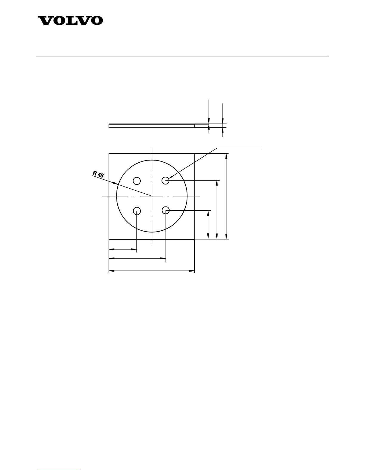
4.11 Spacer, designed to prevent contact with the condensate on the glass plate during reflectometer
measurements, made of a suitable material such as paper or plastic with a circular hole for the measurements. The
thickness of the spacer shall be 0,1 ± 0,02 mm (see Figure 2).
Page 5
Standard STD 420-0003
Volvo Group
Version
1
Page
5
37
73
110
37
73
110
Point of measur ing
0,1
±
0,02
3
±
0,2
Dimens ions in millimetres
Figure 2 Spacer on top of glass plate
4.12 Dishwasher, preferably connected to a deionized-water or distilled-water supply and possible to operate at
80 °C.
An ordinary domestic dish-washer is not capable of washing at 80 °C and is normally not designed for alkaline
dishwasher detergents.
4.13 Balance, with scale divisions of 0,01 mg.
4.14 Glass plate rack
4.15 Phosphorpentoxide and silica gel
4.16 Stamping apparatus, for circular test pieces 80 ± 1 mm.
4.17 Gloves, powder-free polythene gloves and lint-free cotton gloves.
4.18 Desiccator with suitable drying material
4.19 Lintless paper for industrial cleaning, complying with French Standard NF Q 33-033.
NOTE – This paper with reference A28 432 can be obtained from either:
APURA IIe de France BERNARD
14 avenue Ferdinand de Lesseps, BP 80 BP 102
95190 GOUSSAINVILLE 59332 TOURCOING CEDEX
France France
Page 6
Standard STD 420-0003
Volvo Group
Version
1
Page
6
5 Test pieces
Testing of components shall take place at the earliest one week after the date of manufacture and at the latest four
weeks after the date of manufacture.
Storage of components from the date of manufacture to the test date shall be identical to that of components
supplied to production (same temperature, air humidity, wrapping, etc.).
Test pieces taken out of components shall be produced the same day the testing procedure starts.
In the case of finished products, cut circular test pieces with a diameter of 80 ± 1 mm from the sample. The
thickness of the test pieces can be up to 10 mm. Machine thicker materials on the underside to 10 mm (the
underside is the side facing away from the side which is visible in the vehicle). If other test piece dimensions are
required, these may be as given in the product specification.
When preparing test pieces from materials that cannot be shaped into circular test pieces, the material is cut into
80 mm long pieces of the appropriate profile. A minimum of two test pieces shall be tested.
6 Test procedure
6.1 Method F (reflectometric method, evaluation of fogging using a glossmeter)
6.1.1 Conditioning and drying
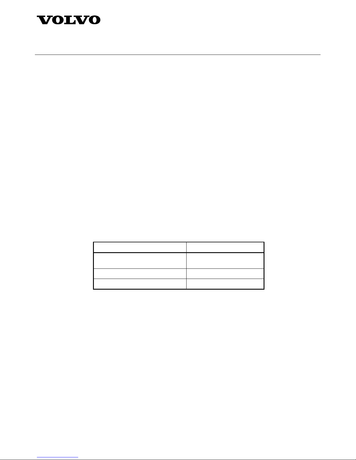
Before the test, the test pieces shall be conditioned at 23 ± 1 °C and 50 ± 5 % RH with a drying time in accordance
with table 1.
Table 1 - Drying times
Material Drying times
Natural materials, test pieces
containing natural materials
168 h ± 2 h
Coated fabrics
48 h ± 2 h
Other materials
24 h ± 2 h
6.1.2 Cleaning
6.1.2.1 Cleaning with a dishwasher
Wash the sealing rings, beakers and metal rings with glass-cleaning detergent twice in a dishwasher. If the
dishwasher is not connected to a deionized-water supply, rinse the cleaned equipment in deio nize d water.
Prior to each use, clean all glass plates twice in dishwater at 80 °C using a glass-cleaning detergent. If the
dishwasher is not connected to a deionized-water supply, rinse the cleaned glass plates in deionized water at room
temperature and dry them in an upright position.
It is recommended to only reuse the glass plates a few times, since microscopic scratches may affect the rate of
deposition of any vapours and hence the reproducibility of the method. Discard any glass plates that have surface
scratches or abraded spots.
Note: Tests have shown that it is very important to use a neutral or acid detergent as alkaline detergent affects the
glass surface and the reflectometer values increase.
After the glass plates have been cleaned and dried, check their cleanliness at a point at which no con densation can
occur during the test by applying a thin film of test fluid (3.4) to the glass surface. The edges of the film shall not
contract within 2 s. Should the edges contract within this time, repeat the cleaning procedure. Should the edges
even after repeated cleaning still contract within 2 s, do not use these plates again for measurements. Ma ke a
visual check that the plates are free of scratches and other defects; if they are not, discard them.
Page 7

Standard STD 420-0003
Volvo Group
Version
1
Page
7
Note: If the film of fluid contracts, this means that the tensile adhesion with the glass is less than the surface
tension of the fluid. If it spreads, the tensile adhesion with the glass is greater than the surface tension of the fluid.
6.1.2.2 Manual cleaning
6.1.2.2.1 General
The seals, metal rings and beakers are washed after each test in accordance with the process describ ed below
(6.1.2.2.2, 6.1.2.2.3 and 6.1.2.2.4) and kept in a dust-free environment between the tests.
The glass plates shall be washed before the test (6.1.2.2.5) and stored for 1 h maximum without coming into
contact with each other, in a dust-free environment.
Note: Avoid using compressed air to dry the material, as this may be a source of heavy pollution.
6.1.2.2.2 Cleaning seals
The seals are washed with the laboratory washing product, rinsed abundantly in water, then in distilled water and
dried at ambient temperature. Before each test, the seals must be placed for 1 h minimum in an oven set to 120 °C
to avoid the release problem.
6.1.2.2.3 Cleaning metal ring
Metal rings are not to be touched with bare hands. The rings are washed with the laboratory washing product,
rinsed abundantly in water, then in distilled water and dried using paper.
6.1.2.2.4 Cleaning of beakers
The beakers must be touched on the outer surfaces only.
The beakers are washed with the laboratory washing product and soft paper, rinsed abundantly in water, then in
distilled water. Allow them to drain for a few moments, then wipe with paper.
If the beakers have contained greasy products or if the specimens have become damaged during the test leaving a
deposit on the bottom of the beakers, the beakers shall be washed in acetone before performing the abovementioned washing procedure.
6.1.2.2.5 Cleaning of glass plates
Wash each plate with a different cotton wad impregnated with acetone so as to remove deposits.
Wash with the laboratory washing product, paper (4.19) and hot water rinse abundantly in water, then in distilled
water.
Dry using paper (4.19), and then place the plates in acetone for 30 minutes minimum.
The acetone baths shall be changed after every 5 operations.
When removed, allow the plates to dry in ambient air. If traces due to evaporation of the acetone appear, rinse the
plate in acetone and dry it with paper (4.19).
Note: The washing stage is highly important, since the appearance of a deposit is greatly dependent on the surface
tension of the glass.
After the glass plates have been cleaned and dried, check their cleanliness at a point at which no con densation can
occur during the test by applying a thin film of test fluid (3.4) to the glass surface. The edges of the film shall not
contract within 2 s. Should the edges contract within this time, repeat the cleaning procedure. Should the edges
even after repeated cleaning still contract within 2 s, do not use these plates again for measurements. Ma ke a
visual check that the plates are free of scratches and other defects; if they are not, discard tem.
Note: If the film of fluid contracts, this means that the tensile adhesion with the glass is less than the surface
tension of the fluid. If it spreads, the tensile adhesion with the glass is greater than the surface tension of the fluid.
Page 8

Standard STD 420-0003
Volvo Group
Version
1
Page
8
6.1.3 Control test with DIDP
At least once a month, a control test shall be carried out in parallel, provided that DIDP is available for purchase
from SP. The test is carried out by pouring 10 g ± 0,1 g of DIDP into the beaker in such a way that the DIDP does
not make contact with the sides of the beaker (above the surface of the fluid).
Place the beaker with the DIDP in the bath, using a different position for each test. After the test period of 180 ± 5
min at the bath temperature of 100 ± 0,5 °C, the fogging value shall be within ± 3 % units of the value stated on the
bottle. If this is not the case, check the test conditions.
The results from the control tests shall be documented and shall be available for reporting in con nection with an
audit of the equipment, etc.
At each inspection, the beaker with DIDP shall be moved between the different openings so that it will not be put in
the same place as during the previous control test.
Observe instructions in accordance with the safety sheet for DIDP.
Note: It is very important not to moisten the walls of the beaker with the DIDP when handling the beaker, as this will
lead to a larger area with DIDP and a higher test result.
6.1.4 Procedure
6.1.4.1 General
The test pieces are placed in beakers with the side that is visible in the car facing up. The sealing ring is placed on
top of the beaker, whereafter the glass plate is placed on the sealing ring.
The beakers with test pieces are placed in the bath that has reached the prescribed temperature.
On top of the glass plate, a filter paper is placed, followed by the cooling plate.
The distance between the bath and the edge of the glass plate shall be 60 mm ± 2 mm. Each time the set
temperature is changed, it is important to check this measure because the fluid volume changes with the
temperature and thus also the distance between the bath and the edge.
The test shall last for 6 h ± 10 min at the prescribed temperature.
At the end of the heat cycle, the glass plates are placed in a rack for 60 min ± 10 min, after which the gloss is
measured.
6.1.4.2 Measuring gloss
The gloss of the glass plates is determined by measuring five points R
01-05
before fogging in accordance with the
glossmeter instructions.
Place the plate in the fixture with the non-tin surface upwards, and focus the measurement on a point in the centre.
The other points to be measured shall be situated 25 mm ± 5 mm from the centre. Measuring shall be done against
a white background. Appropriate is, e.g., a white filter paper. The colour of the filter paper has proved generally
insignificant because the gloss is measured on the surface. However, white filter papers are much more common
than black ones.
The measuring shall be carried out in such a way that it is ensured that the same point is measured before and
after fogging, i.e. R
01=R11
After the fogging test, the measuring is repeated in the same way, i.e. R
11-15
. The mean value of these values is
the fogging which is emitted during the test.
Page 9

Standard STD 420-0003
Volvo Group
Version
1
Page
9
If the gloss readings, Fj, for the test pieces (glass plates) deviate by more than ± 5 % units from the mean value
and none of the test pieces is approved, test a further two glass plates and calculate the mean value of the results
obtained for all test pieces.
6.1.4.3 Calculating the fogging value F
To calculate F in %, the fogging value F
j
is first calculated for each glass plate by using the following equation:
5
100
R
R
F
0501
1511
j
×=
∑
∑
−
−
where
F
j
is the fogging value of each glass plate in %
R
11
is the separate value measured on a glass plate after the fogging tests
R
01
is the separate value measured on a glass plate before the fogging tests
2
21
jj
FF
F
+
=
6.1.4.4 Standard deviation
The standard deviation of fogging factors “F
i
” for each plate is calculated using the formula:
14
)(
4
1
2
−
−
=
∑
=i
ji
j
FF
s
where
F
i
is the fogging value of each point of measuring in %
4 is the number of test points on the glass plate
This standard deviation indicates the homogeneity of the deposit. If the standard deviation is greater than 5 %, or if
the deposit is non-homogeneous, value “F
j
” is not usable and the test must be repeated.
6.2 Method G (gravimetric method, evaluating fogging using a balance)
6.2.1 Conditioning and drying
Before testing, the test pieces shall be dried at 23 ± 1 °C in a dessicator with phosphorpentoxide or silica gel in
accordance with table 2.
Table 2 - Drying times
Material Drying times
Natural materials, test pieces
containing natural materials
168 h ± 2 h
Coated fabrics
48 h ± 2 h
Other materials
24 h ± 2 h
A skin will appear on the phosphorpentoxide or silica gel, which shall carefully be removed. Observe that water
absorption will create phosphoric acid. Attention shall also be paid to instructions as stated in safety sheets for
phosphorpentoxide.
Page 10

Standard STD 420-0003
Volvo Group
Version
1
Page
10
Drying after fogging test
After the fogging test, the aluminium foil shall be dried at 23 ± 1 °C with silica gel for 3 h and 45 min ± 15 min.
When the silica gel has lost its blue colour, it shall be regenerated by driving out the water. The silica gel shall then
be heated in an oven 175 ± 5 °C for at least 30 min.
6.2.2 Cleaning
Wash the sealing rings, beakers and metal rings with glass-cleaning detergent twice in a dishwasher. If the
dishwasher is not connected to a deionized-water supply, rinse the cleaned equipment in deio nize d water.
6.2.3 Control test with DIDP
Once a month a control test shall be carried out in parallell. The test is carried out by pouring 10 g ± 0,1 g of DIDP
into the beaker in such a way that the DIDP does not make contact with the sides of the beaker (above the surface
of the fluid).
Place the beaker with the DIDP in the bath, using different positions for each test. After the test period of 16 ± 0,2 h
at the bath temperature of 100 ± 0,5 °C, the fogging value shall be within ± 0,25 mg of the value stated on the
bottle. If this is not the case, check the test conditions.
At each test, the beaker with DIDP shall be moved between the different positions so that it will not be put in the
same place as during the previous test.
The results from the control tests shall be documented and shall be available for reporting in con nection with any
audit of equipment, etc.
Observe instructions in accordance with the safety sheet for DIDP.
Note: It is very important not to moisten the walls of the beaker with the DIDP when handling the beaker as this will
lead to a larger area with DIDP and a higher test result.
6.2.4 Procedure
6.2.4.1 General
Place one test piece in each beaker with the side that is visible in the car facing up.
Place the sealing ring on the beaker and put the aluminium foil with the shiny side facing down on the sealin g ring,
and place the glass plate on top. Place the beaker in the bath and put a filter paper between the glass plate and the
cooling plate. This shall be done when the required temperature has been reached.
The distance between the bath and the edge of the glass plate shall be 60 mm ± 2 mm (see Figure 1). The test
shall last for 16 h ± 10 min at the prescribed temperature.
After the test, the aluminium foil shall be carefully removed and moved to the dessicator. It shall be dried in a
dessicator with silica gel for 3 h and 45 min ± 15 min with the fogging side facing up (the shiny side). It is important
that the foil is not exposed to direct sunlight while drying.
6.2.4.2 Weighing the aluminium foil
The aluminium foil is weighed before and after the test with an accuracy of ± 0,01 mg. The post-test weighing shall
be carried out after the aluminium foil has been dried in a dessicator with silica gel. Lint-free cotton gloves or
polyethylene gloves shall be used during weighing to avoid contamination.
Carry out measurements on minimum two test pieces. If the mass, Gj, of the condensable constituents deviate by
more than 0,2 mg or 10 % from the mean value, and none of the test pieces is approved, test a further two test
pieces and calculate the average of the results obtained for all test pieces.
Page 11

Standard STD 420-0003
Volvo Group
Version
1
Page
11
6.2.4.3 Calculating the fogging value G
To calculate G in mg, the value of Gj is calculated for each glass plate by using:
G
j
= G1 – G0
where
G
j
is fogging mass of condensation on each piece of aluminium foil
G
1
is the mass of the aluminium foil after the test, in mg
G
0
is the mass of the aluminium foil before the test, in mg
The fogging value G is the mean value of G
j
. G is reported with an accuracy of 0,01 mg.
7 Report
The report shall contain:
- Reference to this standard
- Reference to mehod used (method F evaluation of fogging using a glossmeter or method G gravimetrical
method, evaluation of fogging using a balance)
- Identification of test pieces
- Date of production
- Type of test pieces
- Thickness of the test pieces
- Date of test
- Person responsible for testing
- Any deviations from standard
- Results: mean value and individual values
- Number of test pieces tested
- Any particular observations.
8 Temperature options
The temperature shall be stated in the documentation referring to this standard.
 Loading...