

Page 1
Standard STD 101-0001
Volvo Group
Established
December 2007
Version
4
Page
1(36)
The English language version is the original and the reference in case of dispute.
BASIC RULES FOR REPRESENTATION
Digital product-definition data practices
Orientation
This standard is based on the international standard ISO 16792:2006 and the Am erican standard
ASME 14.41-2003.
The technical content of section 3, dealing with the combination of drawing and Digital Shape Model
(DSM), corresponds to version 3 of this standard.
This version differs from version 3 in that the title of the standard has been changed from Digital Shape Model
basis – DSM basis to Digital product-definition data practices, which is equal to the title of ISO 16792. In order to
bring the standard in line with ISO 16792, the contents have been completely re-worked and sections 2 Terms
and definitions, 4 Model-only and 5 Reference to this standard on model have been added.
Contents
1 Scope and field of application
2 Terms and definitions
3 Drawing and Digital Shape Model (DSM) in combination
3.1 Reference on drawing
4 Model-only
4.1 General model requirements
4.2 Digital Shape Model (DSM) requirements
4.3 Common requirements for product-definition data
4.4 General notes and local notes
4.5 Model values and dimensions
4.6 Datum applications
4.7 Geometrical tolerances
4.8 Surface texture
4.9 Other applications of 3-D annotation
5 References to this standard on model
1 Scope and field of application
This standard specifies requirements for the preparation and presentation of digital produ ct-definition data,
hereafter referred to as data sets. It supports two methods of application: model-only, and model and d ra wing in
digital format.
Some parts of the standard are primarily intended as guidelines for IT engineers, but may also be
of general interest. These parts have been marked with the following symbol in the right-hand
margin of the standard.
The rules are intended for use within all Business units and Business areas of the Volvo Group. However, before
starting using model-only (annotated models), the method shall be approved for use within each org anization in
question. For approval, this check list shall be used:
• Are all necessary functionalities implemented in the concerned CAD systems?
• Is there a clear business case (e.g. shorter lead-times, increased quality)?
• Are all down-stream systems and work processes aligned (purchasing, manufacturing, aftermarket, etc.)?
Page 2
Standard STD 101-0001
Volvo Group
Version
4
Page
2
NOTE: The figures included in this standard are merely intended to illustrate how annotations shall or can be
made in 3-D environment. They are not intended as recommendations when choosing type of tolerance, size of
tolerance zone, etc. Nor are the illustrations intended to show the complete set of requirements needed to define
a part.
2 Terms and definitions
For the purposes of this standard, the following terms and definitions apply:
annotation
dimension(s), tolerance(s), note(s), text or symbol(s) visible without any manual or external manipulation
annotation plane
conceptual plane containing annotation
NOTE 1 − It is desirable that annotation planes intersect or coincide with a model feature.
NOTE 2 − The plane is “conceptual” because it is not physically shown as geometry on the model, but is provided to
replace the drawing media.
associated entities
portion of a product definition to which annotation pertains
associated group
user-defined set of related digital elements
associativity
established relationship between digital elements
attribute
dimension, tolerance, note, text or symbol required to complete the product definition or model feature of the
product that is not visible but available upon querying the model
digital shape model (DSM)
portion of the data set that contains model geometry and supplemental geometry
NOTE 1 − In ISO 16792:2006, the term design model is used to denote this concept.
digital element
geometric element, model feature, group of model features, annotation, associated group or attribute that exists in
a data set
model geometry
geometric elements in product definition data which represent a designed part
geometric element
graphic entity used in a data set
EXAMPLES Representation of geometric feature as defined in ISO 14660-1, representation of model coordinate
system, or representation of crosshatching.
management data
data required for the release, control and storage of product-definition data as well as other relevant engineering
data
model
combination of digital shape model, annotation and attributes that describes a part
model feature
model geometry that represents a physical portion of a part
model value
numerical value derived by querying the model that quantifies the form and spatial relationships of the geometry
composing a digital shape model or assembly of models to the precision (number of decimal places) of the
computer system
Page 3
Standard STD 101-0001
Volvo Group
Version
4
Page
3
query
means of interrogating a digital element or the relationship between digital elements
represented line element
supplemental geometry line or curve segment indicating the orientation of a direction-dependent tolerance
resolved dimension
model value that is rounded to the number of decimal places required for the design
supplemental geometry
geometric elements included in product-definition data to communicate design requirements but not intended to
represent a portion of the manufactured product
3 Drawing and Digital Shape Model (DSM) in combination
In order to provide a complete definition of a part, a drawing and a digital shape model (DSM) are often used in
combination as primary documents. In such cases, the following fundamental requirements and other provisions
apply:
• When dimensions and other properties are indicated on the drawing, these apply.
• Dimensions displayed on the drawing are considered resolved dimensions. These must not be in conflict
with dimensions obtained from the model; however they shall be rounded to the number of decimal places
required for the design. See section 4.5.2.2.
• Dimensions, e.g. theoretically exact dimensions, which are not displayed on the drawing, shall be
obtained by querying the model.
• Values obtained from the model for any feature(s) where no tolerance or datum target specification has
been stated, shall be considered auxiliary dimensions.
The part may be represented on a drawing using one or more orthographic or ax onometric views and sections.
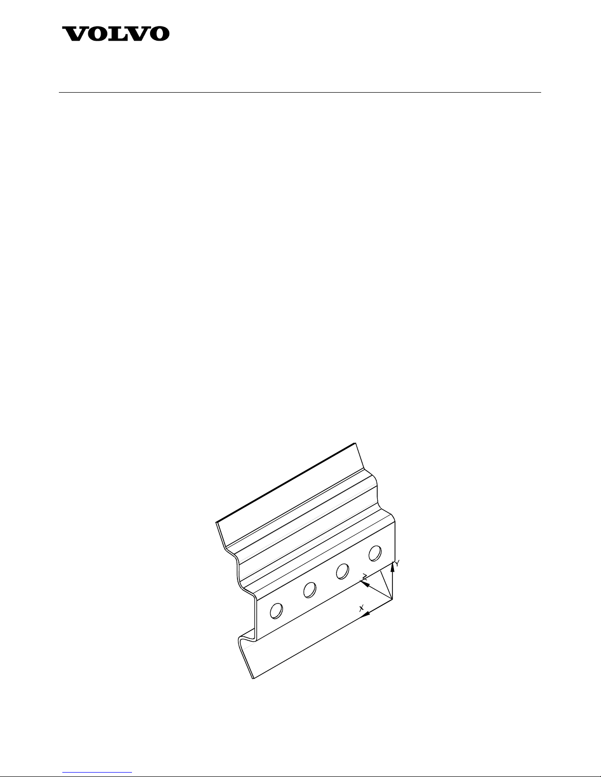
Figure 1 shows a digital shape model without any annotation. A drawing shall be used along with it to provide
geometric and other requirements.
Figure 1 - Digital Shape Model (DSM)
Page 4
Standard STD 101-0001
Volvo Group
Version
4
Page
4
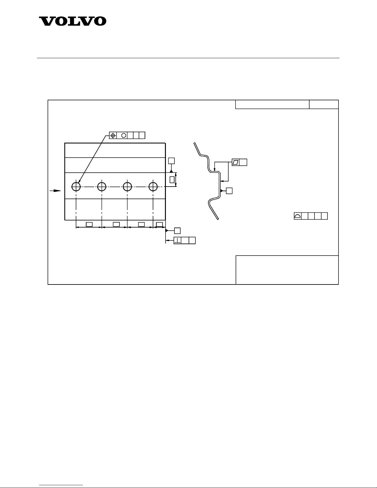
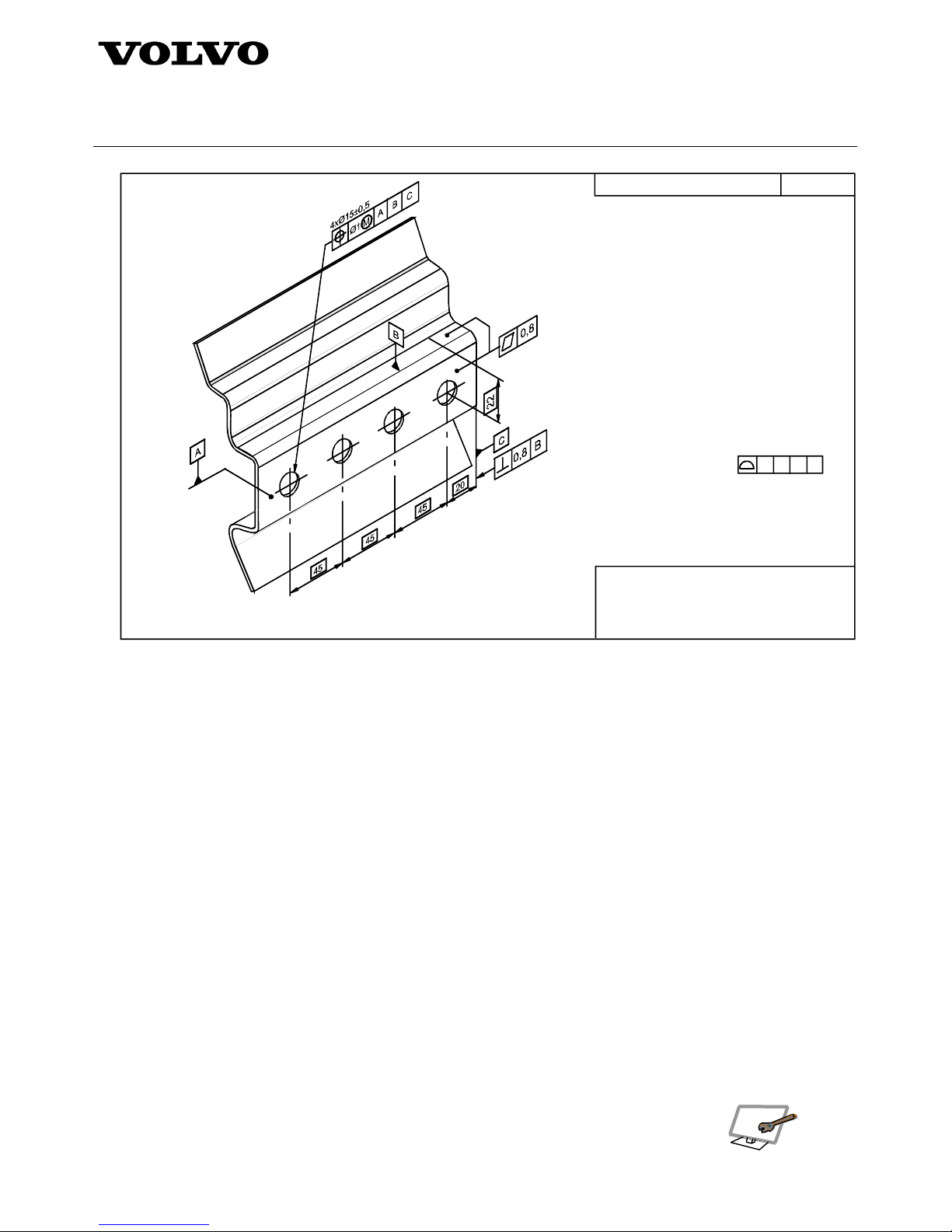
Figure 2 gives an example of an orthographic drawing depicting the modelled part and figure 3 shows an
axonometric drawing stating the same requirements. Irrespective of the method used to depict the part,
orthographic or axonometric, the drawing shall contain a note stating that DSM is basis for dimensions not stated
on the drawing, and also give reference to this standard. See also section 3.1.
20
40
40
40
22
A
B
C
A
A
1234567X
Ø1 M
A B C
4xØ15±0,5
0,8 B
0,8
UNLESS OTHERWISE STATED
DIGITAL SHAPE MODEL
IS BASIS WHERE DIMENSIONS ARE OMITTED
STD 101-0001
SYMBOLS, DESIGNATIONS AND GENERAL DRAWING
METHODS STD 101-0005
A B C
2
Figure 2 – Orthographic engineering drawing to be used along with the DSM
Page 5
Standard STD 101-0001
Volvo Group
Version
4
Page
5
1234567X
UNLESS OTHERWISE STATED
DIGITAL SHAPE MODEL
IS BASIS WHERE DIMENSIONS ARE OMITTED
STD 101-0001
SYMBOLS, DE S IGNATIONS A ND GENERAL DRAWING
METHODS STD 101-0005
A B C
2
Figure 3 – Axonometric engineering drawing to be used along with the DSM
3.1 Reference on drawing
When a drawing shall be used in combination with a digital shape model (DSM) in order to provide a complete
definition of a part, the following text note shall be indicated in the text space of the drawing:
DIGITAL SHAPE MODEL
IS BASIS WHERE DIMENSIONS ARE OMITTED
STD 101-0001
In exceptional case, when the model number of the DSM is not linked to the part through the main document in
the PDM system, it may be included in the text note on the drawing in accordance with the following example:
DIGITAL SHAPE MODEL No: xxxxxxxx
IS BASIS WHERE DIMENSIONS ARE OMITTED
STD 101-0001
4 Model-only
4.1 General model requirements
The data set shall provide complete product definition. For example, a DSM, its annotation, and related
documentation.
4.1.1 Fundamental principles
The following are the fundamental requirements and other provisions applicable to annotated model s.
• The ability to query the model shall be available.
Page 6
Standard STD 101-0001
Volvo Group
Version
4
Page
6
• All angular values shall be queried from the model. Exceptions to this are model coordinate system(s) and
planes and axes in datum systems.
• Annotation in any given annotation plane shall not overlap other annotation in the same annotation plane
when the model is viewed perpendicular to the annotation plane.
• Annotation text within any given annotation plane shall not be placed over the DSM when the model is
viewed perpendicular to the annotation plane.
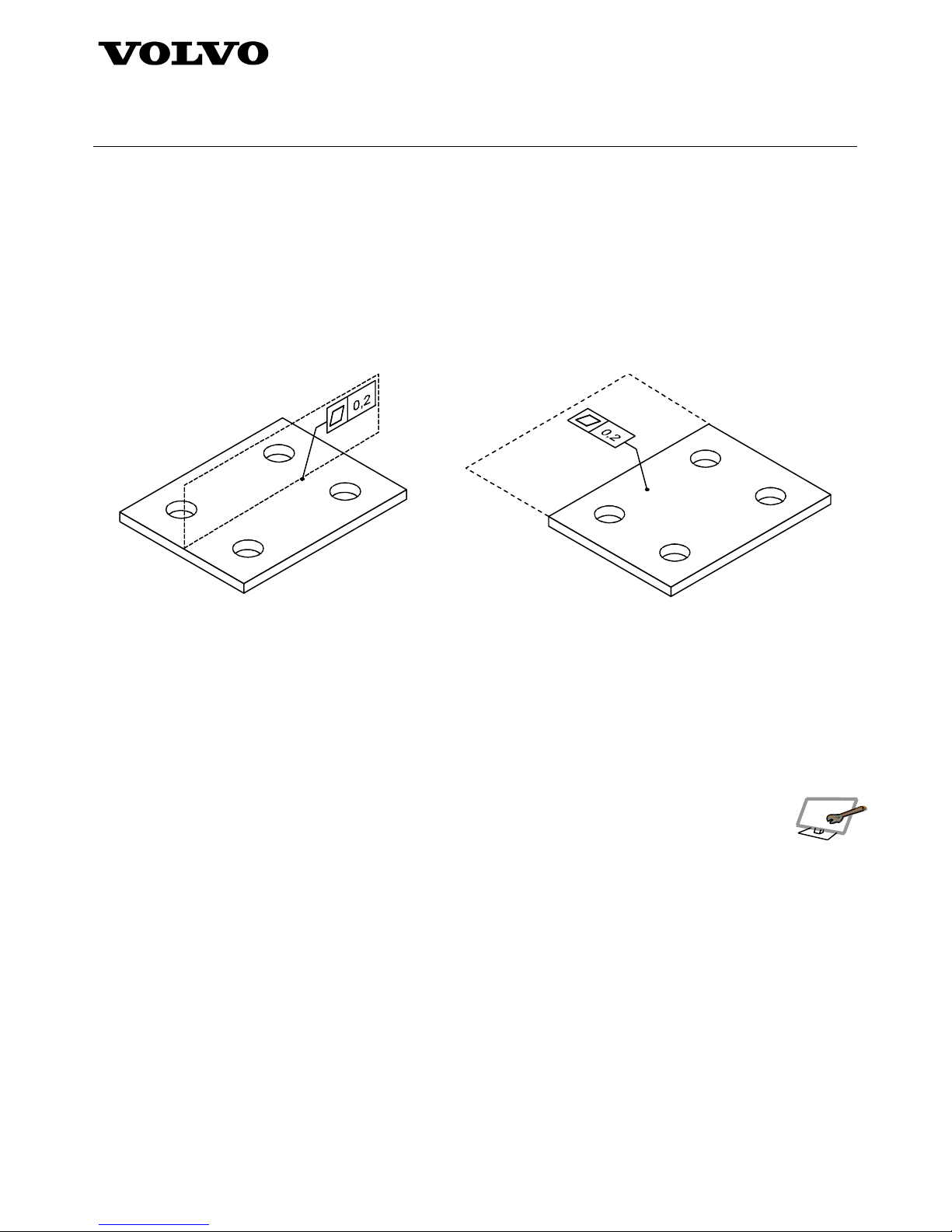
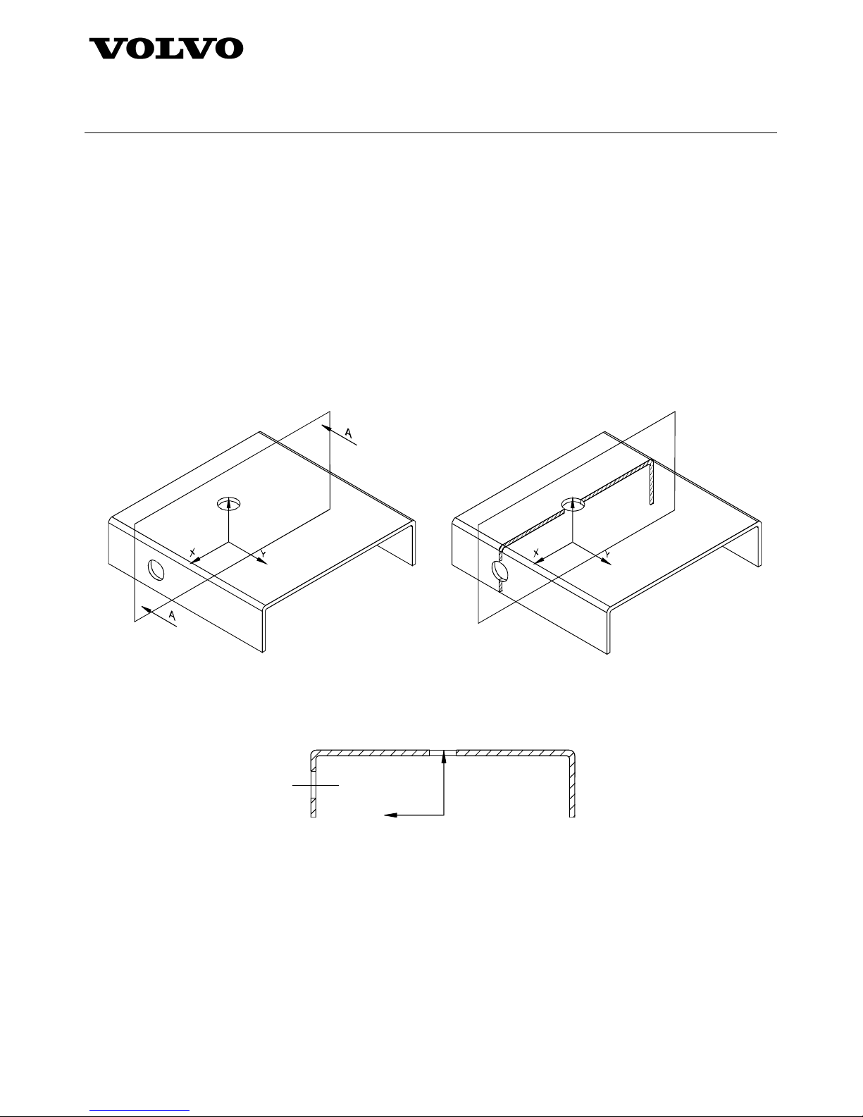
• All annotation shall be specified in one or more annotation planes. Figure 4 shows the principle of using
annotation planes. When CAD software does not support maintenance of annotation-plane o rientation
relative to the model, the model-only method shall not be used.
a) Perpendicular annotation plane
b) Coincident annotation plane
Figure 4 – General application of perpendicular or coincident annotation plan e
• The associated entities, annotations, and attributes shall be in agreement.
• Resolved dimensions created from queried model values are considere d the same as dimensions
displayed on a model.
• Display of centrelines or centre planes for features of size is optional.
• To ensure that the annotation is readable
− the text, for example, could be upside down or
backwards following rotation of the model
− one of the following techniques shall be used:
o ensuring that the reading direction is updated after rotation of a model
o inclusion of means of determining the correct reading direction in each annotation
plane applied to a model
o when using saved views, ensuring that the model is orientated in the intended view direction
− for
example, by including a means of determining the correct reading direction in the view.
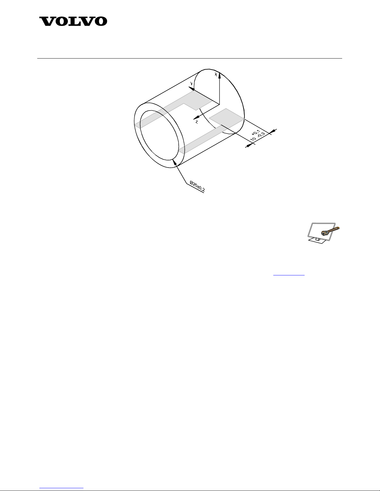
• Dimensions and tolerances to internal features may be shown without the use of a section. See figure 5.
Page 7
Standard STD 101-0001
Volvo Group
Version
4
Page
7
Figure 5 – Showing internal features without using a section
4.1.2 Associativity
The ability to associate digital elements shall be available and maintained. Associativity
information shall be electronically accessible.
4.1.3 Model coordinate systems
A DSM shall contain one or more model coordinate systems. For further information regarding model coordinate
systems, see ISO 16792:2006. Concerning coordinate systems for heavy vehicles, se e
STD 5026,1.
4.1.4 Applications of supplemental geometry
When supplemental geometry is used, there shall be a clear distinction between the supplemental geometry and
the model geometry.
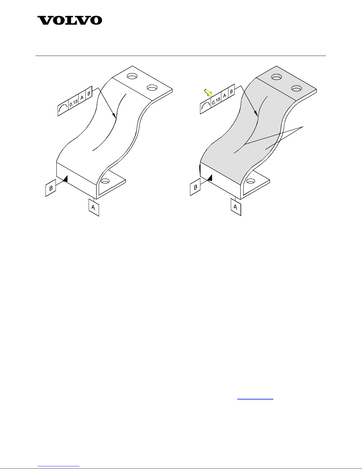
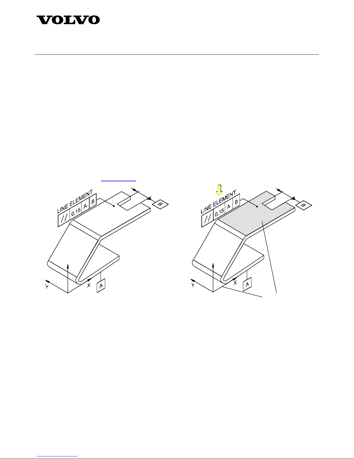
a) Represented line element
The following geometric tolerances may use a represented line element to clarify the direction of a twodimensional tolerance zone of parallel lines. When a represented line element is used to indicate the
direction of a geometric tolerance application, the leader from the tolerance indicator shall terminate on
the represented line element in an arrowhead, see figure 6a. The following geometric tolerances may use
a represented line element to clarify the directionality of a two-dimensional tolerance zone of parallel lines:
• Straightness applied to the line elements of a planar surface.
• Orientation tolerance applied on each line element on a surface.
• Profile any line. See figure 6a.
Page 8
Standard STD 101-0001
Volvo Group
Version
4
Page
8
Query
Visual response
Figure 6a Figure 6b
b) Associativity
The represented line element, the tolerance frame and the controlled feature should be organized as an
associated group, see figure 6b.
4.1.5 Part features not fully modelled
A conventional simplified representation of part features such as threads and splines may be shown using a
partial geometry definition, annotations, attributes or a combination thereof.
4.1.6 General methods requirements
4.1.6.1 Data set methods
The following subsections cover the product-definition methods listed below. Each different method for specifying
product definition is used in support of different industry processes and requirements. The data set is the original
for all the methods. Any copy, no matter what the media of presentation, is subordinate.
4.1.6.2 Model only
The following is applicable when a model, but no drawing, is used as primary document in the definition of a part.
a) Product-definition data including, but not limited to notes, marking requirements, dimensions and
tolerances shall be contained or referenced in the data set.
4.1.7 Title block on model
When model-only (annotated models) is used, a title block in accordance with STD 910-0001 shall be included in
the model. The title block shall be placed on the general-notes annotation plane which is possible to display on
request and which does not rotate with the model. See section 4.4.
Page 9
Standard STD 101-0001
Volvo Group
Version
4
Page
9
4.1.8 Views and sections on models
4.1.8.1 Views on models
Saved views of a DSM may be defined to facilitate presentation of the model and its annotation. A saved view
shall have an identifier, be retrievable on demand, contain a model co-ordinate system that denotes the direction
of the view relative to the model and may contain one or more of the annotation plane(s), a selected set of
annotation, or a selected set of geometry.
4.1.8.2 Sections
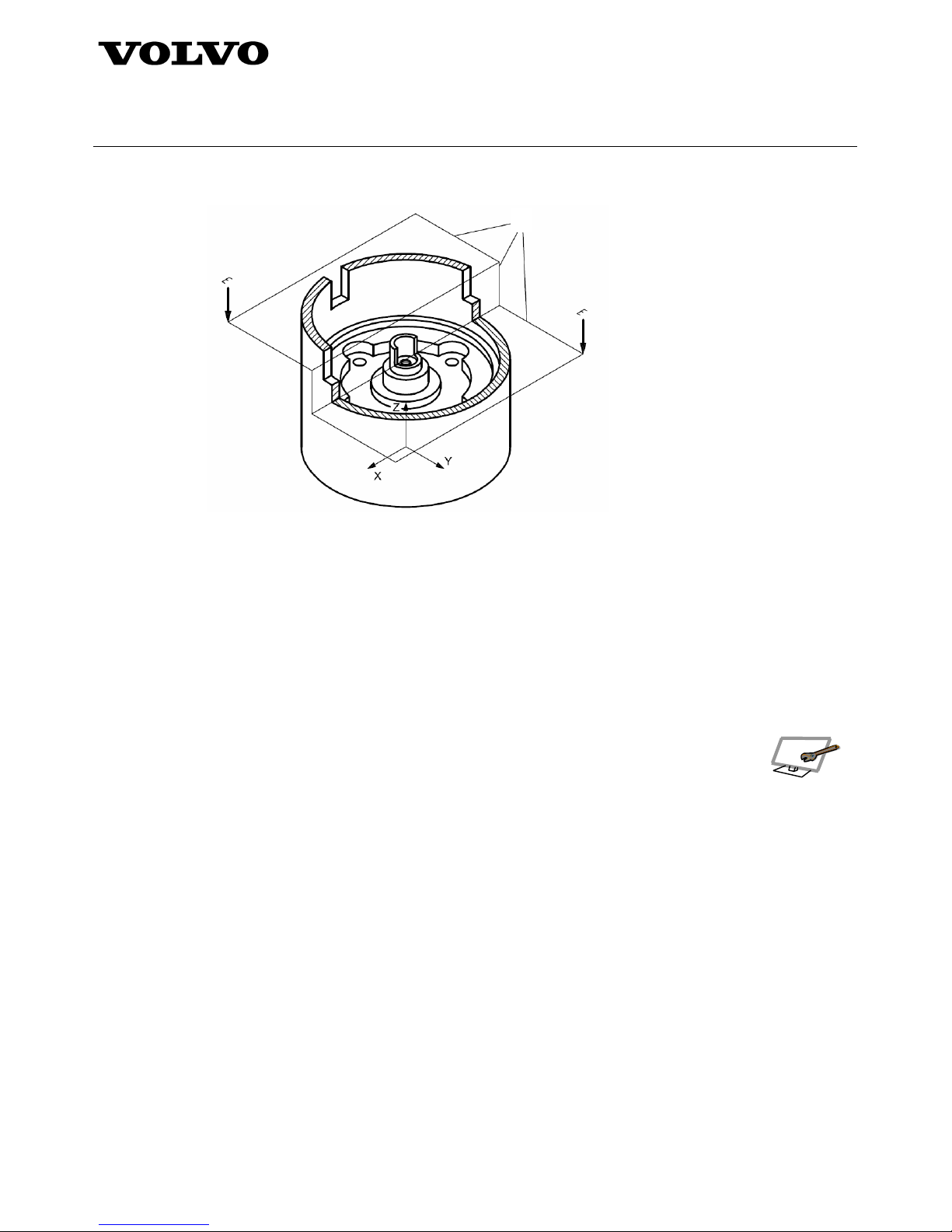
Saved views may be used to retain sections. All sections shall be the same scale as the DSM. A representation of
a cutting plane shall be used to indicate the location and viewing direction of a section. A means to identify all
cutting planes in a model shall be available. A visible viewing arrow or arrows shall be included to show the
direction in which the section is viewed, see figure 7. When the resultant section is shown as curves in the model,
the viewing arrows can be omitted.
Z
Z
Figure 7a - DSM cutting plane Figure 7b - Re sultant section shown on curves in the
model
A - A
X
Z
Figure 7c - Resultant section in saved view
Page 10
Standard STD 101-0001
Volvo Group
Version
4
Page
10
Multiple connected cutting planes shall be used for offset sections. See figure 8.
Multiple connected cutting planes
Figure 8 – DSM with offset section
4.2 Digital shape model (DSM) requirements
4.2.1 General
Digital shape models (DSM) represent a part in ideal geometric form at a particular dimensional condition. Unless
otherwise stated as a general note in the general-notes annotation plane, the dimensional condition applied for
the model shall be that all features are modelled at the nominal size from which the upper and lower limits of size
are derived.
4.2.2 Geometric scale and precision
DSMs shall be modelled using scale 1:1.The model precision indicates the numeric
accuracy required in the production of the part in order to fulfil the design intent. The
number of significant digits of the DSM shall be specified in the data set. The number of
decimal places required for the design cannot exceed the precision of the DSM.
4.2.3 Model completeness
The model shall contain geometry, attributes and annotation as required to provide a complete definition of the
part. The model shall be constructed so as to provide a complete definition of the part. In the event this facility is
not used, e.g. in early stages
• models not fully modelled shall be identified as such, e.g. a partially modelled symmetrical part,
• features that are not fully modelled shall be identified as such, e.g. threaded holes that are only shown as
holes, and
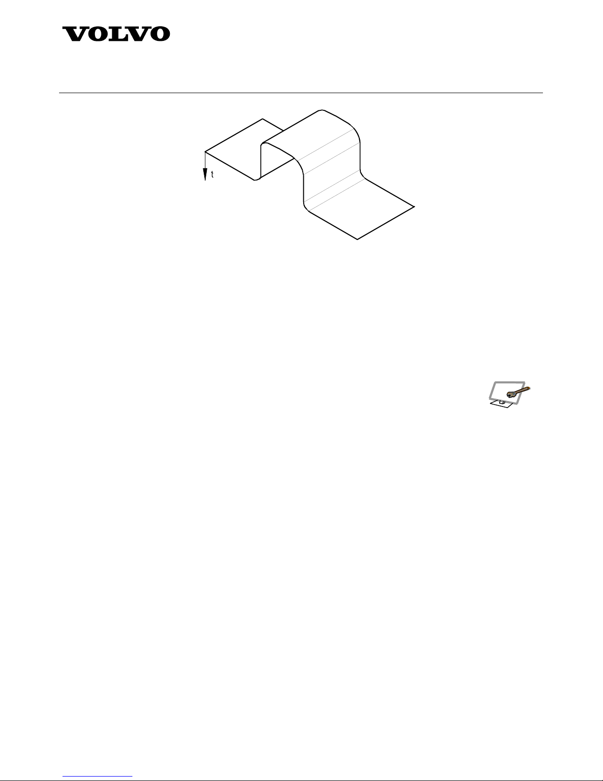
• thin parts for which the thickness has not been fully modelled, see figure 9.
Page 11
Standard STD 101-0001
Volvo Group
Version
4
Page
11
Figure 9 – Thickness indicator for a non-modelled thin part
4.3 Common requirements for product-definition data
4.3.1 General
This section establishes the common requirements for the application, display management and query of product
definition data. Specific requirements for particular types of product-definition data are given in sections 4.4 to 4.9.
4.3.2 Common requirements
4.3.2.1 Display management
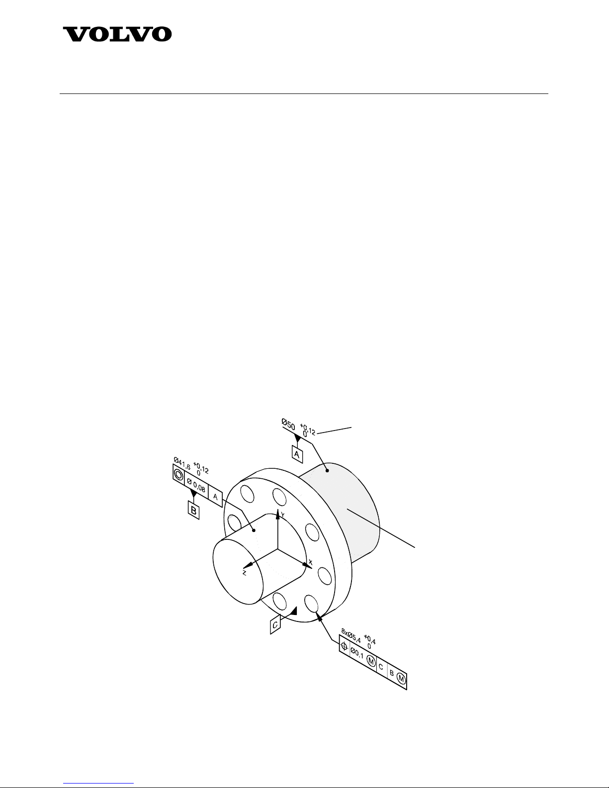
Display management shall include the ability to enable or disable the display of annotations
completely, by type or selectively.
Page 12
Standard STD 101-0001
Volvo Group
Version
4
Page
12
Ra 6,3
+0,3
General notes:
Z
a) Model with all annotations displayed
Figure 10 – Display management
Page 13
Standard STD 101-0001
Volvo Group
Version
4
Page
13
Z
b) Model with one type of annotation displayed
Figure 7 (continued)
Ra 6,3
+0,3
General notes:
Z
c) Model with selected annotations displayed
Figure 10 (continued)
Page 14
Standard STD 101-0001
Volvo Group
Version
4
Page
14
4.3.2.2 Hard copy
For working purpose, a hard copy of any visual display shall be available on demand. This hard copy is for
reference only.
4.3.3 Model requirements
4.3.3.1 General
The following subsections give requirements for annotation applied to a DSM. These are general requirements,
which apply to all types of annotation. Specific requirements for particular types of annotation are addressed in
sections 4.4 to 4.9.
4.3.3.2 Associativity
The following are general provisions for defining an associative relationship between digital elements.
Annotation shall be associated to a model feature, a group of features, or a portion of an applicable model feature,
for example, the associated entities for a dimension.
Annotation, model geometry, and supplemental geometry may be placed in associated groups to indicate their
relationships.
See figure 11.
Example 1: Supplemental geometry used to define location, orientation, or further clarify the application of
annotation to a model.
Example 2: A model coordinate system for datum systems.
Example 3: Qualifying notes and size limit indications.
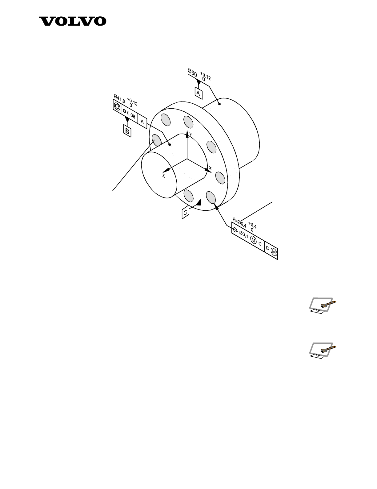
Query
Visual response
a) Size tolerance query
Figure 11 – Tolerance query associativity
Page 15
Standard STD 101-0001
Volvo Group
Version
4
Page
15
Query
Visual response
(eight associative features)
b) Pattern of features query
Figure 11 (continued)
4.3.3.3 Attributes
Attributes are used to capture additional information that is not shown using geometry or in the
model annotation. Attributes shall be available on demand. Attributes may be presented using
text description, forms or other techniques. Applications of attributes include, but are not
limited to hardening, coating, knurling, screw threads and centre holes.
4.3.3.4 Annotation planes
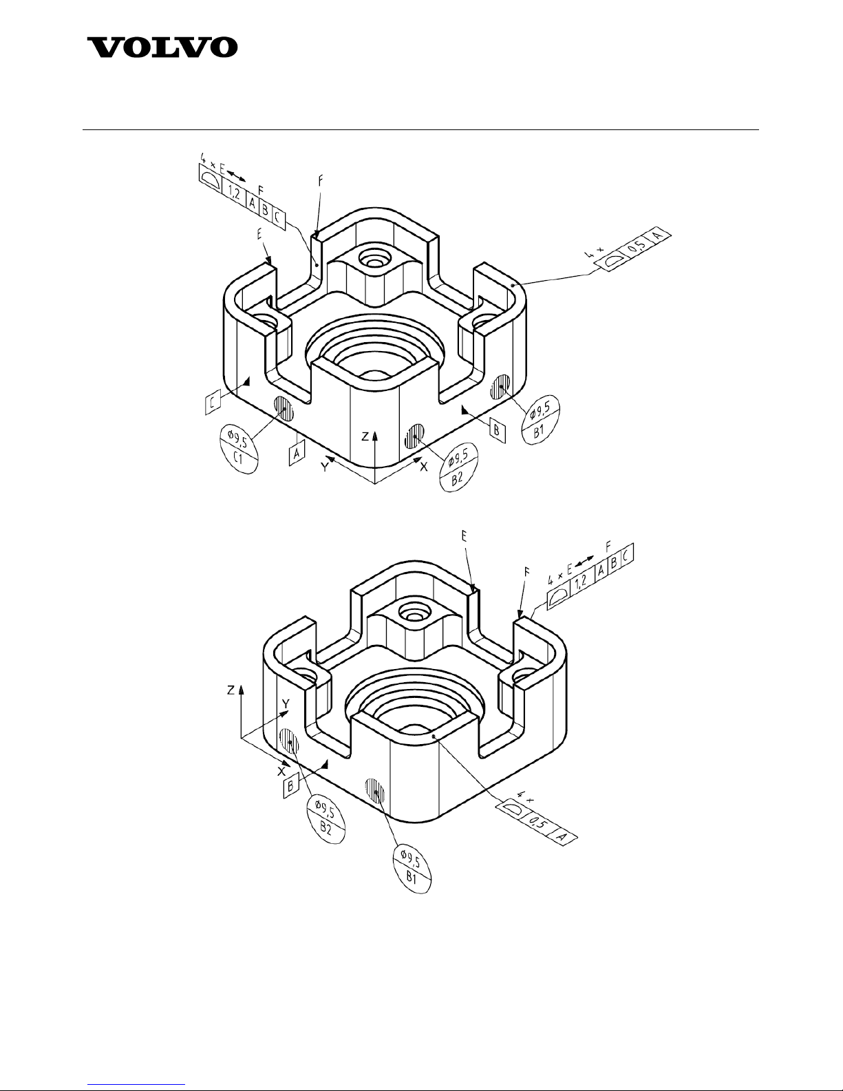
The orientation of the annotation plane shall be maintained relative to model geometry as the
model is manipulated in 3-D. For example, as the geometry is rotated, the text rotates correspondingly. See figure 12. When a CAD system does not support maintenance of annotation
plane orientation relative to the model, annotation planes shall not be used.
Page 16
Standard STD 101-0001
Volvo Group
Version
4
Page
16
a) Initial attitude of model geometry and annotation
b) Rotated about 90° about the Z axis
Figure 12 – Annotation planes relative to model geometry
Page 17
Standard STD 101-0001
Volvo Group
Version
4
Page
17
4.3.3.5 Leader lines
Leader lines directed to represented line elements shall terminate with an arrowhead. When an indicated element
is a surface, the leader line shall terminate with a dot within the bounds of the surface. Leader lines may terminate
on the rim or edge of a feature of size if this provides a clearer understanding of the intention of the annotation. A
continuous (solid) leader line shall be used to indicate all datum targets in a DSM.
4.3.3.6 Direction-dependent tolerances
When a direction-dependent tolerance (e.g. straightness) is applied to a DSM, the direction shall be explicitly
defined as follows.
• Supplemented geometry is added to the model to show the direction of application. The model geometry
to which the tolerance applies shall be the associated geometry for the annotation, see figures 6a and 6b.
• Direction-dependent tolerances may use a model-coordinate-system vector to define the direction of
application. The model coordinate system vector, associated entity and tolerance shall be organized as
an associated group, see figure 13.
• As indicated in
STD 112-0003 – Geometrical tolerances.
Z
Visual response
Query
Z
Figure 13 – Direction of tolerance defined by coordinate system vector
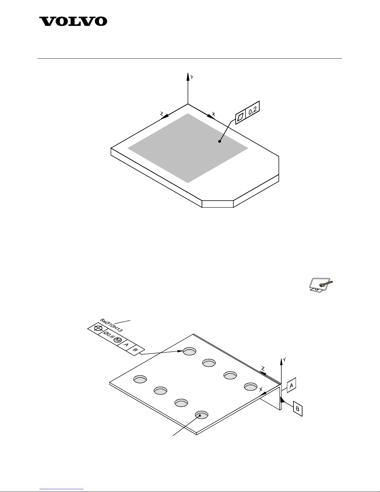
4.3.3.7 Indicated limited application of a tolerance
Limited length, area and location indicators may consist of, but are not limited to, supplemental geometry and
associative annotation. When supplemental geometry is used, it shall be located on the model geometry, see
figure 14.
Page 18
Standard STD 101-0001
Volvo Group
Version
4
Page
18
Figure 14 – Limited-area indicator
4.3.3.8 Query types
The model shall contain information sufficient to satisfy the following query types.
a) Model values
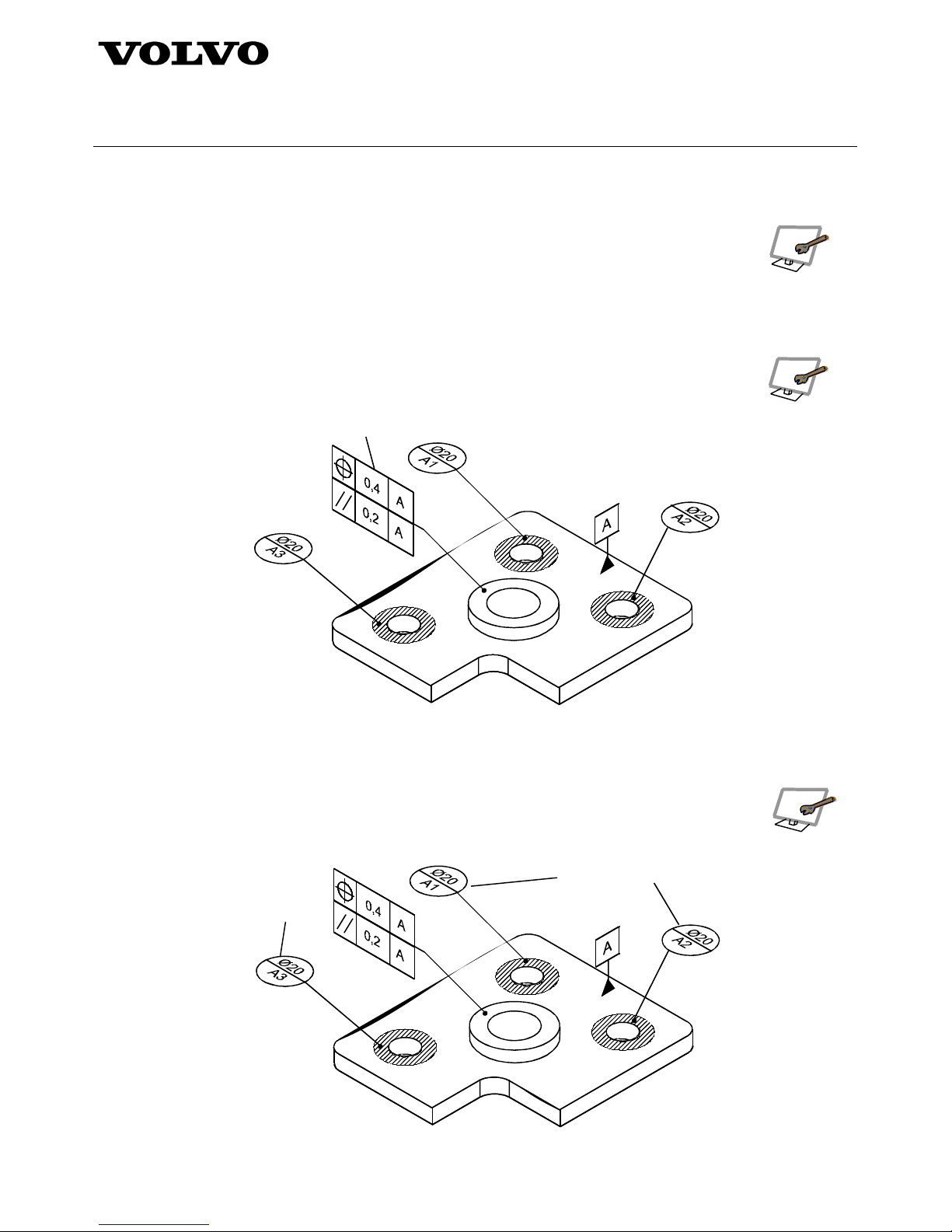
b) Relationship between model geometry and annotation in either direction, including the following:
• Graphic display of associated entities: the associated entities for a piece of
annotation shall be highlighted or otherwise distinguished from other entities on the
display on demand, see figures 11a) and b).
• Graphic display of associated annotation: all annotations associated with selected
geometry or model features shall be highlighted or otherwise distinguished from
other entities on demand, see figure 15.
Query
Visual
response
Figure 15 – One feature of a pattern
Page 19
Standard STD 101-0001
Volvo Group
Version
4
Page
19
c) Model geometry and model features
• Model features shall be identifiable by selecting a geometric element of the model
feature.
• All geometric elements in an associated group of model features shall be
identifiable by selecting any geometric element within the group.
• All model features in a group of model features shall be identifiable by selecting
one of the model features
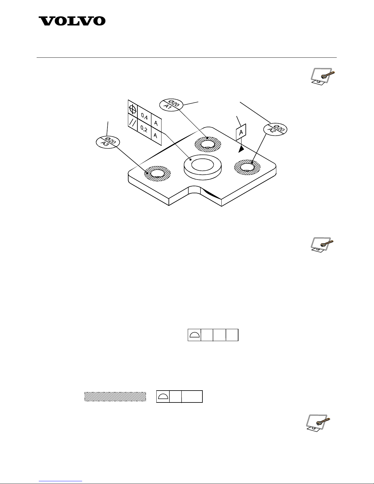
d) Tolerance indicators, datum indicators and datum target indicators
• Upon selection of a tolerance indicator, the datum indicators and datum target
indicators that correspond to the datum references shall be highlighted or
otherwise distinguished from other entities on the display, see figure 16.
Query
Visual response: All datum feature symbols and datum target symbols respond
Figure 16 – Queries of datum feature symbols and datum target symbols
• Upon selection of a datum target indicator, all datum target indicators sharing the
same letter shall be highlighted or otherwise distinguished from other entities of the
display, see figure 17
Query
Visual response
Figure 17 – Queries for datum targets
Page 20
Standard STD 101-0001
Volvo Group
Version
4
Page
20
• Upon selection of a datum indicator, the datum target indicators which have the same
datum letter shall be highlighted or otherwise distinguished from other entities on the
display, see figure 18.
Visual response
Query
Visual
response
Figure 18 – Queries for supplemental geometry
e) Supplemental geometry used in the definition of annotations, appropriately highlighted or
otherwise from other entities on the display.
f) Identification of all elements of an associated group, appropriately highlighted or otherwise
distinguished from other entities on the display, through the selection of any one element.
4.4 General notes and local notes
4.4.1 Model requirements
When a requirement of a particular type is generally applied or applicable to features not associated to another
requirement of the same type, a general note can be stated and placed in a notes-annotation plane
(corresponding to text space of a drawing) that does not rotate with the model. This annotation plane shall be
available for display with the model.
Example:
UNLESS OTHERWISE STATED
2 A B
When special requirements apply to one or a few digital elements or areas of the modelled part, but are
unsuitable to specify in a model-annotation plane, a reference symbol, e.g. 1), A), symbol, etc. shall be placed in a
model annotation plane and repeated in the notes-annotation plane (text space) along with the applicable
requirement. These notes are called local notes.
Example
MATING SURFACES
General notes do not require associativity. General notes may include general tolerances for
the entire model. Local notes shall be associative to applicable digital elements in the model.
1 XYZ
Page 21
Standard STD 101-0001
Volvo Group
Version
4
Page
21
4.5 Model values and dimensions
4.5.1 General
This section establishes the requirements for model-value query, and resolved theoretically exact and radial
dimensions, linear and angular distance, and size and limits of dimensions in a data set. It also contains the
common requirements for associativity and dimensions on a model or drawing.
4.5.2 Common requirements
4.5.2.1 Model-value queries
The following model-value queries shall always be conducted in relation to the absolute or
a user-defined model coordinate system of the DSM:
• determination of location and orientation of surfaces
• determination of distance or angle between two surfaces
• determination of the position (location and orientation) of features of size
• determination of the feature relation (hole-to-hole spacing and orientation) dimensions within a pattern of
features of size.
Direct query of the model surface or model feature of size is usually conducted for
• determining the shape (curvature) of surfaces, and
• determining size value for a feature of size or a pattern of features of size.
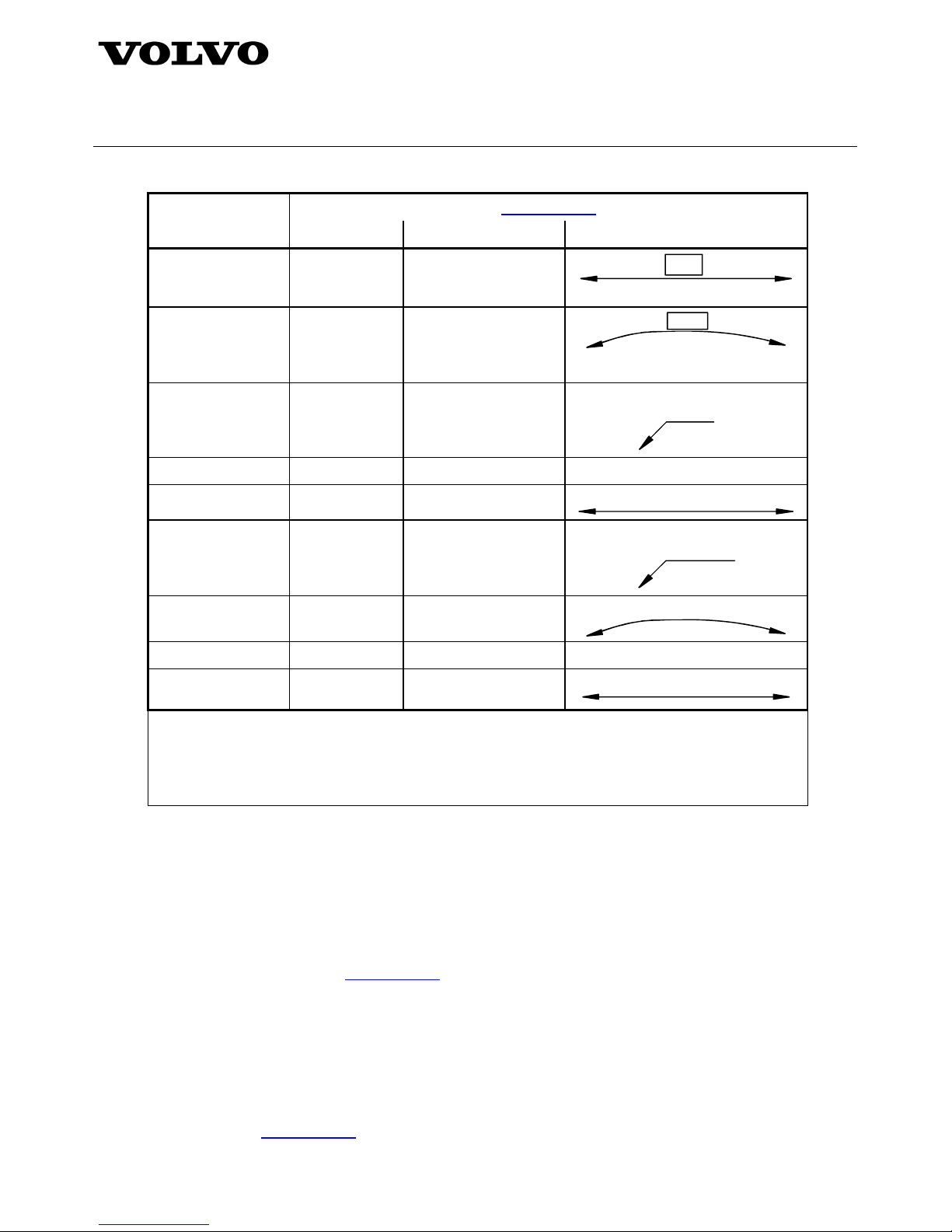
4.5.2.2 Resolved dimensions
Dimensions displayed on a model are resolved dimensions. For examples of resolving model
values to displayed dimensions, see table 1. The requirements for resolved dimensions
follow.
a) To obtain a resolved dimension, a model value shall be rounded to the number of decimal places
required for the design.
b) All resolved dimensions shall be absolute values.
c) Rounding shall be in accordance with ISO 31-0:1992.
d) Resolved dimension preservation and association: a direct and permanent association to the
originating model value shall be established and maintained for every resolved dimension.
e) Utilization of model or resolved dimensions: the use of model values or resolved dimensions for
analyses and other processes shall be defined in appropriate documentation.
Page 22
Standard STD 101-0001
Volvo Group
Version
4
Page
22
Table 1 – Resolved dimension examples
STD 101-0001
Model value
a
Resolved dimension a Application example
88,4
Linear theoretically
exact dimension
(linear TED)
b
88,4100000 … 88,4
28,6°
28,5918273 … 28,6
Angular
theoretically exact
dimension (angular
TED)
b
Size c
Ø7,5
Ø7,0
7,0000000 … 7,0
Size 45,700000 45,7 45,7h7
19,67±0,12
Linear distance 19,6666666 … 19,67
+0,8
R 3,2 0
Radial distance 3,1500000 … 3,2
28,6°±0,4°
Angular dimension 28,5918273 … 28,6
Unilateral limit b 12,0000000 … 12 12 MIN
(21,6)
21,6018043 … 21,6
Auxiliary
dimension
b
a. The values shown are examples. Actual values will reflect the defined precision of the
model and the rounding requirements of each particular application.
b. Linear, radial, angular, diametrical or spherical diameter.
c. Linear, diame t rical or spherical diameter.
4.5.3 Model requirements
Requirements for attaching and displaying theoretically exact dimensions, size value s and pl us and minus
tolerances on a model are defined in the following subsections.
4.5.3.1 Theoretically exact and nominal dimensions
Queried model values for features fully constrained by geometrical tolerances shall be interpreted as theoretically
exact dimensions, in accordance with
STD 112-0003. In all other circumstances, queried model values not defined
by a specific tolerance or identified as an auxiliary dimension shall be interpreted as a nominal dimen sion, i.e.
covered by a general tolerance.
a) Querying of the model for the profile, location, and orientation of a feature shall occur within the appropriate
model coordinate system.
b) The display of theoretically exact dimensions may be necessary in defining some model relationships. This
is applicable to an inclined datum feature and to features that may appear to be 90
° but for which the actual
model angle is other than this. Displayed theoretically exact dimensions shall be enclosed in a box in
accordance with
STD 112-0003.
Page 23
Standard STD 101-0001
Volvo Group
Version
4
Page
23
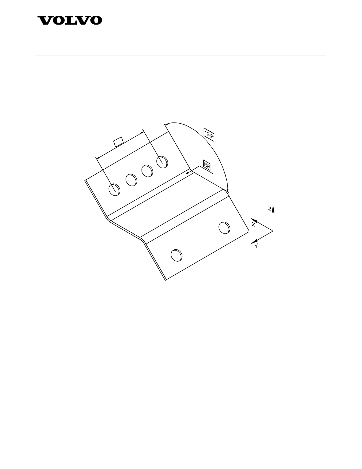
c) Theoretically exact dimensions should be placed in annotation planes that are parallel with one of the
planes of the absolute or a user-defined model co-ordinate system. An example of an exception is the 3x15
basic dimension shown in figure 19.
d) Theoretically exact dimensions defining surface curvature or extent , such as fillets, rounds or chamfers,
shall be directed to the feature surface by a leader line, see figure 19.
e) Theoretically exact dimensions defining linear distance or angular relation are shown using dimension and
extension lines, see figure 19.
3
x
1
5
(
=
45
)
Figure 19 – Placement and attachment for theoretically exact dimensions
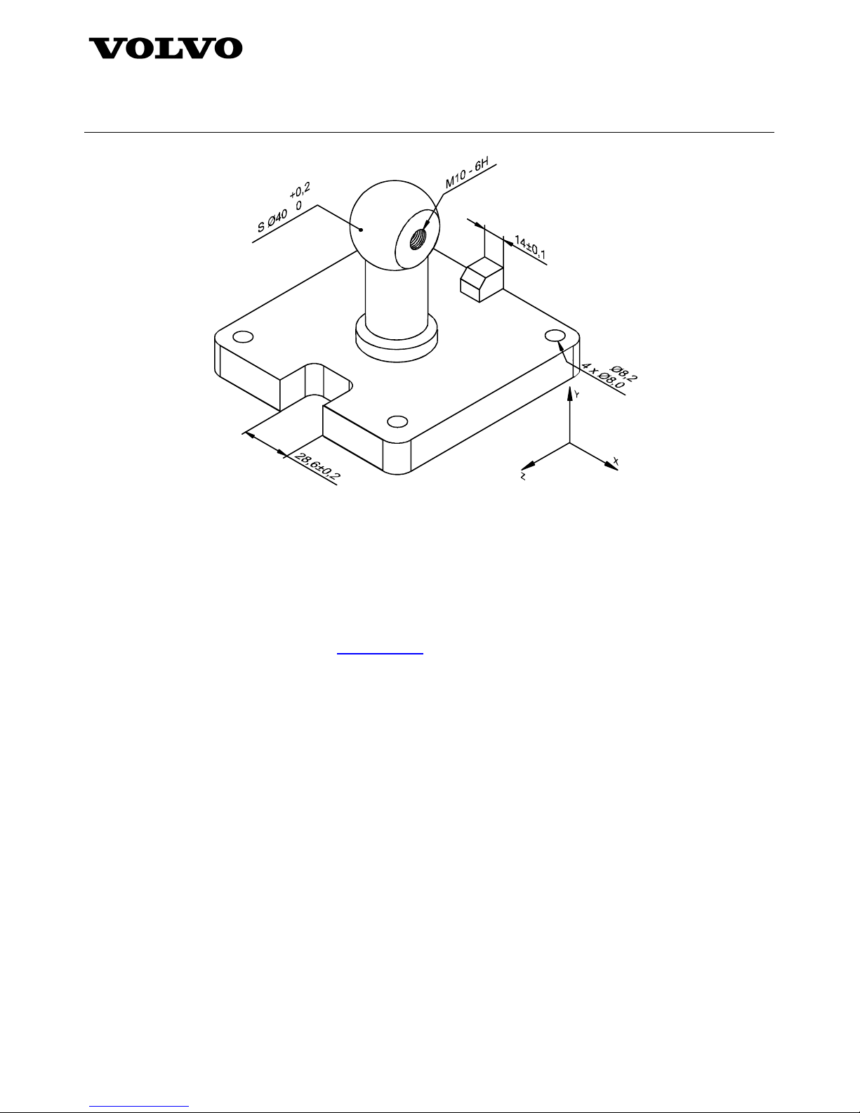
4.5.3.2 Size values
A size value shall not conflict with a queried model value for the same feature when the model value is rounded to
the same number of decimal places. This agreement shall meet one of the following requirements, depending on
the tolerance expression used.
For bilateral or unilateral tolerances, the displayed size value shall equal the resolved model value.
For size values, the placement and attachment methods for size dimension s are as follo ws:
• Spherical surface: the size value, leader line or dimension and extension line s sh all be placed on an
annotation plane containing the model feature centre-point.
• Cylindrical surface: the size value, leader line or dimension and extension lines shall be placed on an
annotation plane perpendicular to the model feature axis or containing the model feature axis.
• Set of two opposed parallel surfaces (a width): the size value, dimension, and extension lines shall be
placed on an annotation plane perpendicular to, or containing, the feature centre plane; the extension lines
shall clearly indicate the surfaces comprising the width, see figure 20 for examples.
Page 24
Standard STD 101-0001
Volvo Group
Version
4
Page
24
Figure 20 – Placement and attachment for linear dimensions
4.6 Datum applications
This section establishes practices for organizing, attaching and di splaying datum indicators, datum target indicators
and related information associative with models. Requirements and recommendations for correlating datum
features to the coordinate axes of the model space are given.
4.6.1 Model requirements
In 3-D annotation, the rules from standard STD 112-0002 – Datums and datum system apply with the following
exception and addition:
• The datum indicator shall not be attached on a single extension line of model feature outlines.
NOTE: This is an unambiguous method in orthographic views to represent a surface, but it cannot be used on a 3-D
model where it becomes indistinct.
4.6.1.1 Datum system and model coordinate
The following requirements apply to the relationship between the datum systems on the model and the model
coordinate systems:
a) Datum system and coordinate system correspondence
Each datum system shall be associated to a corresponding model coordinate system.
b) Datum system and coordinate system associativity
A definite visual relationship between any datum system and the corresponding coordinate system shall be
preserved throughout navigation and query of the presented design data.
c) Multiple datum system and coordinate system relationship
When more than one datum system is imposed upon the model, each datum system-to-coordinate sy ste m
relationship shall be clearly presented and maintained.
Page 25
Standard STD 101-0001
Volvo Group
Version
4
Page
25
4.6.1.2 Identification of datums
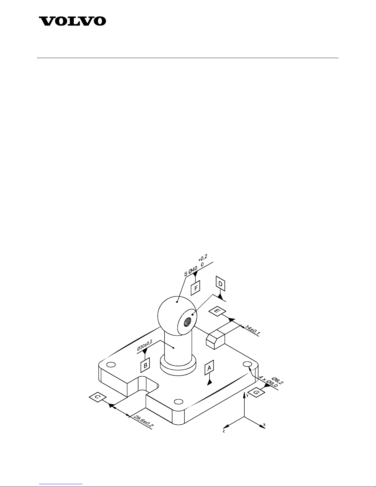
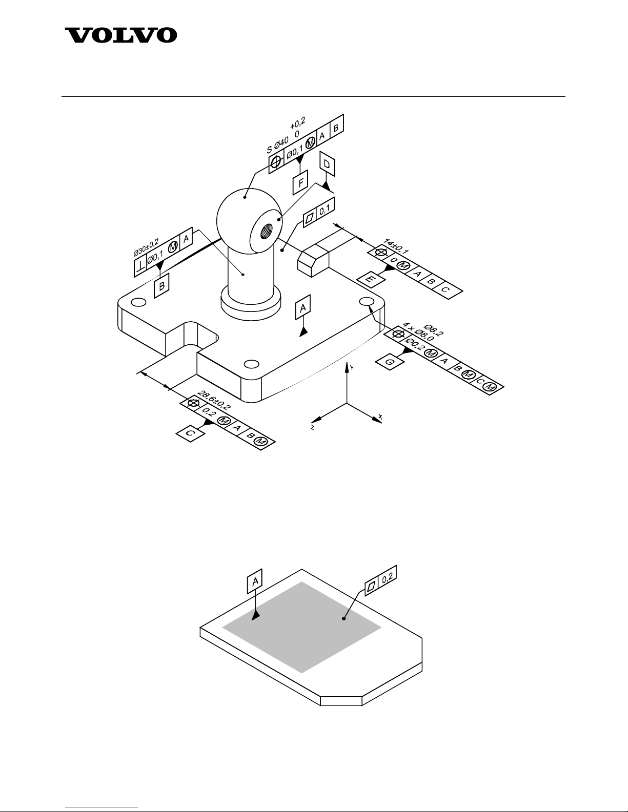
Figures 21 and 22 demonstrate symbol attachment methods for identifying datums on a model. The datum
indicator should be attached to the surface representing the datum feature. Single extension lines of model feature
outlines should not be used for the attachment of datum indicators. Particular requirements and the preferred
attachment methods for datum indicators are as follows:
a) Identification of planar surface (integral feature)
The datum indicator shall be attached directly to the surface (see datum A in figure 21 a) or to a reference
line using a leader line terminated with a dot to the surface (see datum D in figure 21 a).
b) Identification of the centre point of a spherical feature (derived feature)
The datum indicator shall be attached to the reference line for the dimension (see datum F in figure 21a).
or to the tolerance indicator as shown in figure 21b.
c) Identification of an axis on a cylindrical feature (derived feature)
The datum indicator shall be attached to a reference line and using a leader line terminated with a dot to
the surface (see datum B in figure 21a).
NOTE: It is also possible to attach the datum indicator as an extension of the dimension line as shown for
two opposed parallel planes in figure 21a, but this often becomes impractical for diameters in 3-D.
d) Identification of the median plane of two opposed parallel planes (a width) (derived feature)
The datum indicator shall be attached as an extension of the dimension line as shown in figure 21a or to
the tolerance frame as shown in figure 21b.
a) Direct attachment
Figure 21 – Datum indicator attachments
Page 26
Standard STD 101-0001
Volvo Group
Version
4
Page
26
b) Tolerance frames
Figure 21 (continued)
e) Identification of restricted area application (integral feature)
When a restricted area of a surface is used as datum feature, this limited area of application shall be
represented on the model using supplemental geometry. The datum indicator can be attached directly to
the surface (see figure 22), to the tolerance frame if, for example, a flatness requirement applies to the
same surface or to a reference line using a leader line that terminates with a dot on the surface.
Figure 22 – Partial surface as datum feature
Page 27
Standard STD 101-0001
Volvo Group
Version
4
Page
27
4.6.1.3 Associativity of datum features and design data
A query of any datum feature shall permit access to all relevant information for the datum feature.
This includes the datum indicator, the size limits (if applicable), any applied geometric toleran ce,
and the relevant coordinate system.
4.6.1.4 Identification of datum targets
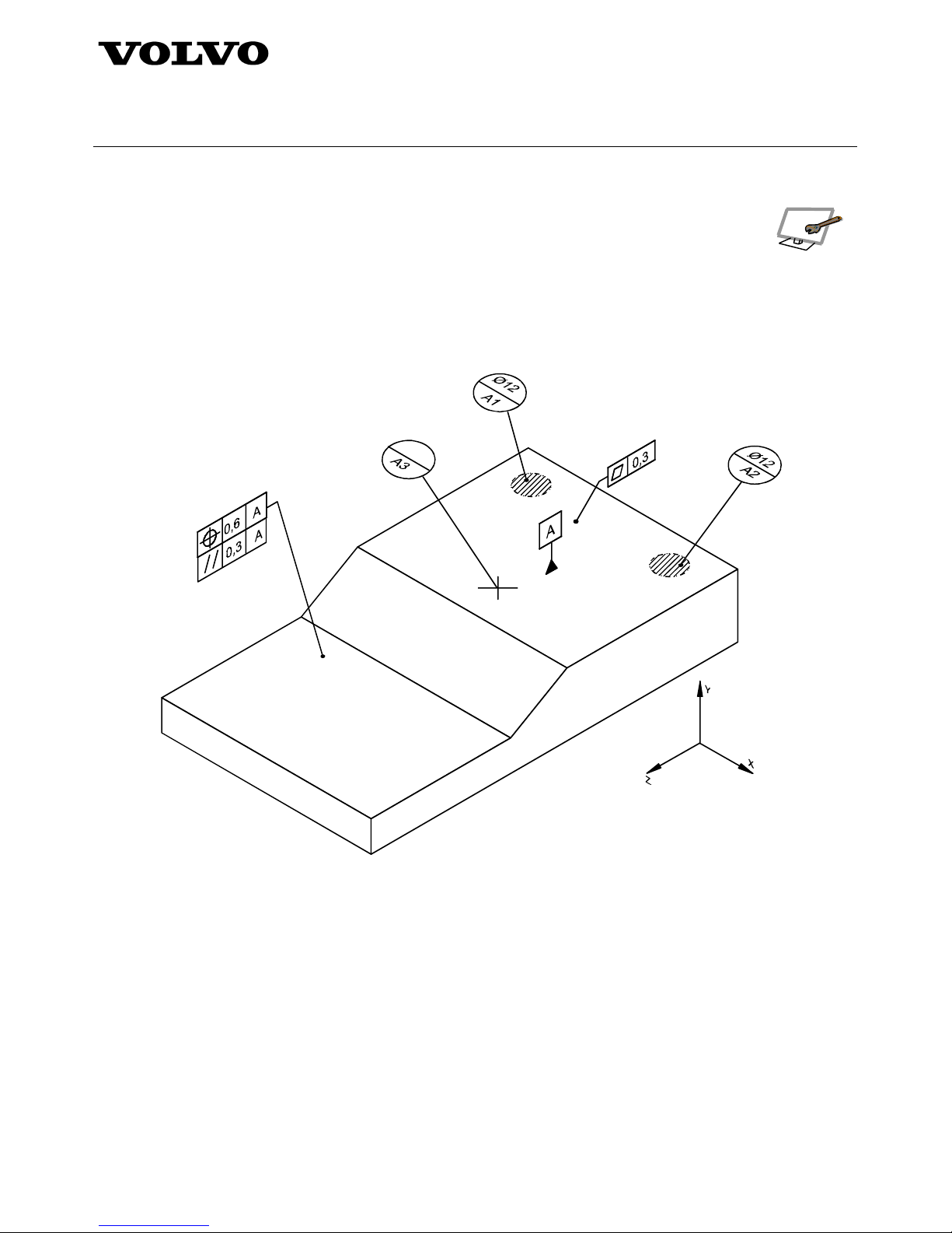
In figure 23, an example of using datum targets is shown. Datum targets can be areas or points.
Datum target areas shall be shown using shading or crosshatching, and datum targets points are shown wi th a
cross. See figure 23.
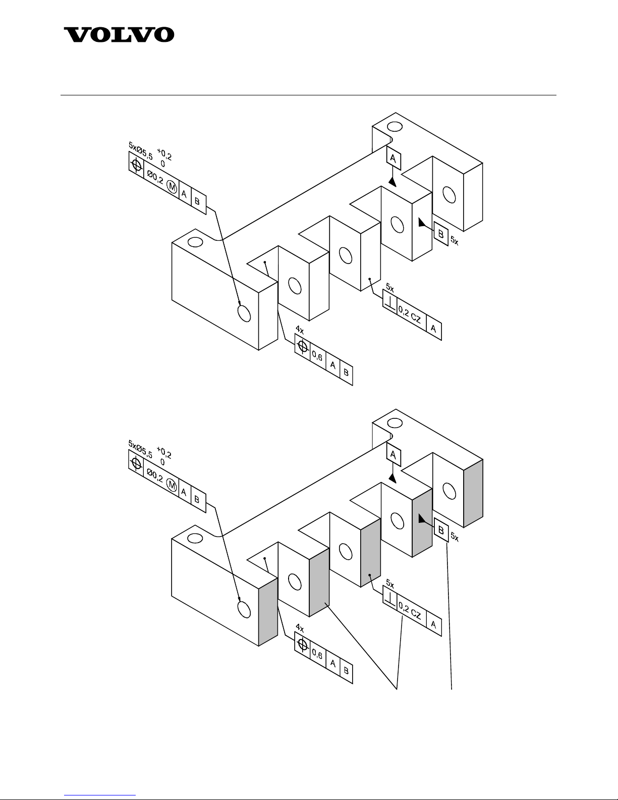
Figure 23 – Datum targets and indicators attachment
4.6.1.5 Multiple features establishing a datum
When two or more features are combined to establish a datum, associativity shall be established in the design
presentation.
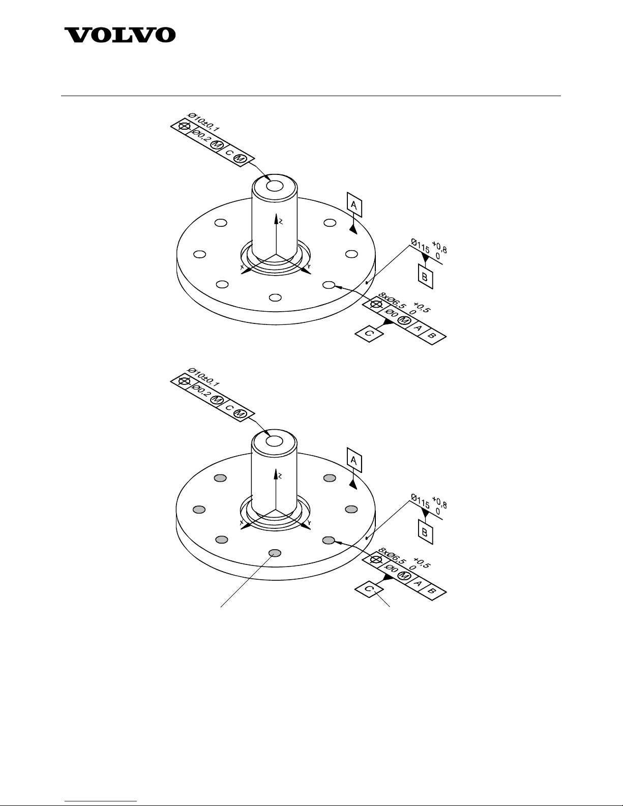
a) When a pattern of features of size is used to establish a datum axis, the involved model features and any
applied tolerance for these model features shall be organized as an associated group. See figure 24.
Page 28
Standard STD 101-0001
Volvo Group
Version
4
Page
28
a) Placement and attachment
Query
Visual response
b) Datum feature indicator associativity
Figure 24 – Pattern of features establish a datum axis
b) When two or more co-planar surface features are used to establish a datum plan e, the involved model
surfaces and any applied tolerance for these surfaces shall be organized as an asso ciated group, see
figure 25.
Page 29
Standard STD 101-0001
Volvo Group
Version
4
Page
29
a) Placement and attachment
Visual response Query
b) Datum feature indicator associativity
Figure 25 – Co-planar surfaces establish a datum plane
Page 30
Standard STD 101-0001
Volvo Group
Version
4
Page
30
4.7 Geometrical tolerances
In this section, rules for the connection of the tolerance frames to the toleranced features in 3-D environment are
given. Some of these rules differ from the rules stated in
STD 112-0003 which mainly are intended for orthographic
engineering drawings.
Some examples of various tolerance indications in accordance with the rules given in this stan dard are also shown.
4.7.1 Toleranced features
4.7.1.1 The line or the surface itself
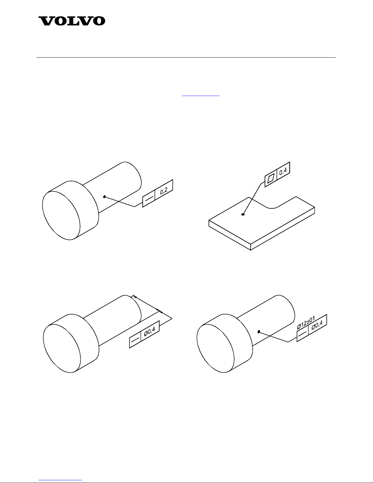
When a tolerance applies to a line or to the surface itself, the tolerance frame shall be connected to the toleranced
feature by a leader line that ends with a dot on the surface. See examples in figures 26 and 27.
Figure 26 Figure 27
4.7.1.2 The axis of a cylinder
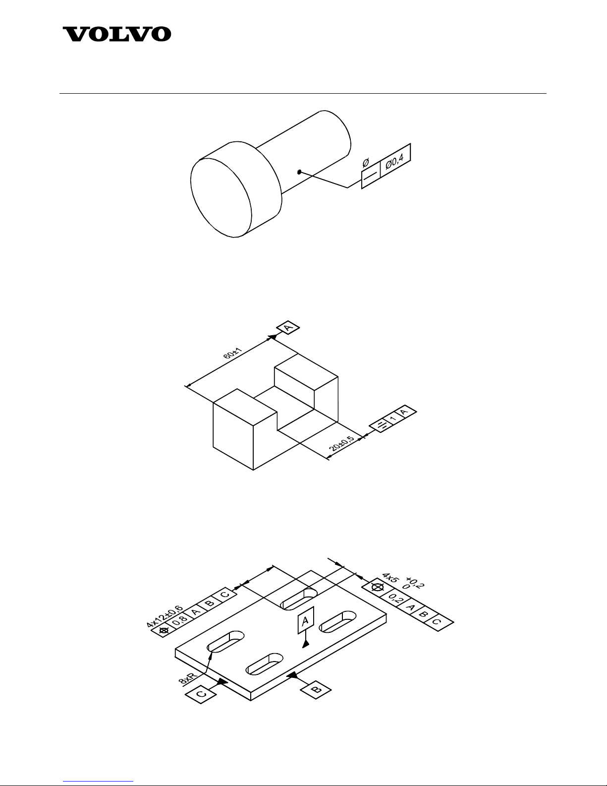
When the tolerance applies to the axis of a cylinder, this shall be indicated in accordance with one of the ways
shown in figures 28 – 30.
Figure 28 – Current 2-D rule. This can also be used
in 3-D but will often become impractical
Figure 29 – Recommended 3-D method, which is to
connect the leader line with a dot to the
surface and to specify the size dimension
above the tolerance frame
Page 31
Standard STD 101-0001
Volvo Group
Version
4
Page
31
Figure 30 - The same example as shown in figure 29 but without stating the size dimension above the tolerance
frame. In this case, the
∅ symbol shall be indicated above the tolerance frame
4.7.1.3 A median plane of a width
If the tolerance applies to the median plane of a width, the tolerance frame shall be connected as an extension of
the dimension line. See figure 31.
Figure 31
NOTE - This is identical to the 2-D rule.
4.7.1.4 A centre point, an axis or a median plane in one direction
When a tolerance applies to a centre point, an axis or a median plane in one direction, the tolerance frame shall be
connected as an extension of the dimension line.
Figure 32
NOTE - This is identical to the 2-D rule.
Page 32
Standard STD 101-0001
Volvo Group
Version
4
Page
32
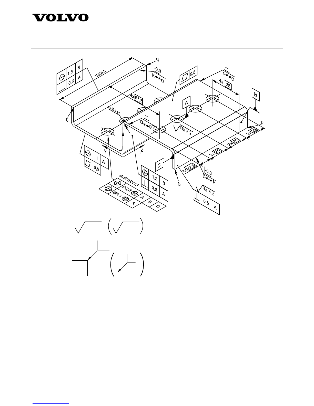
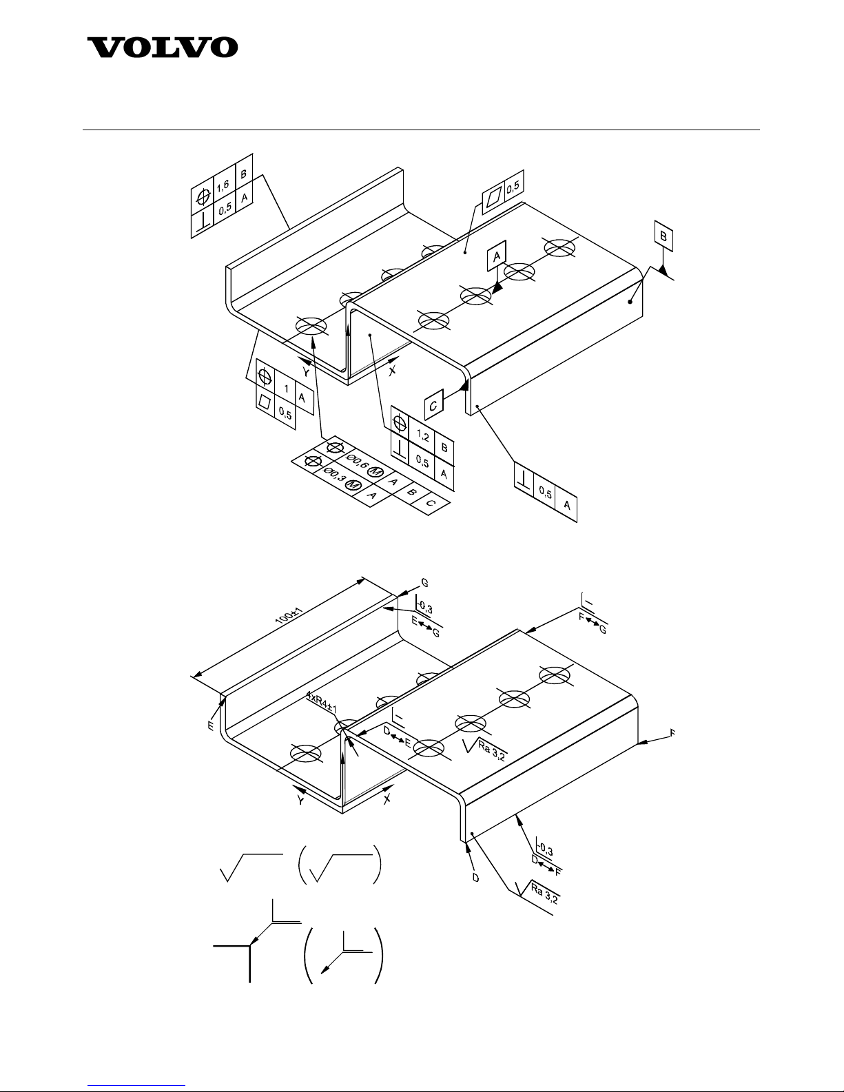
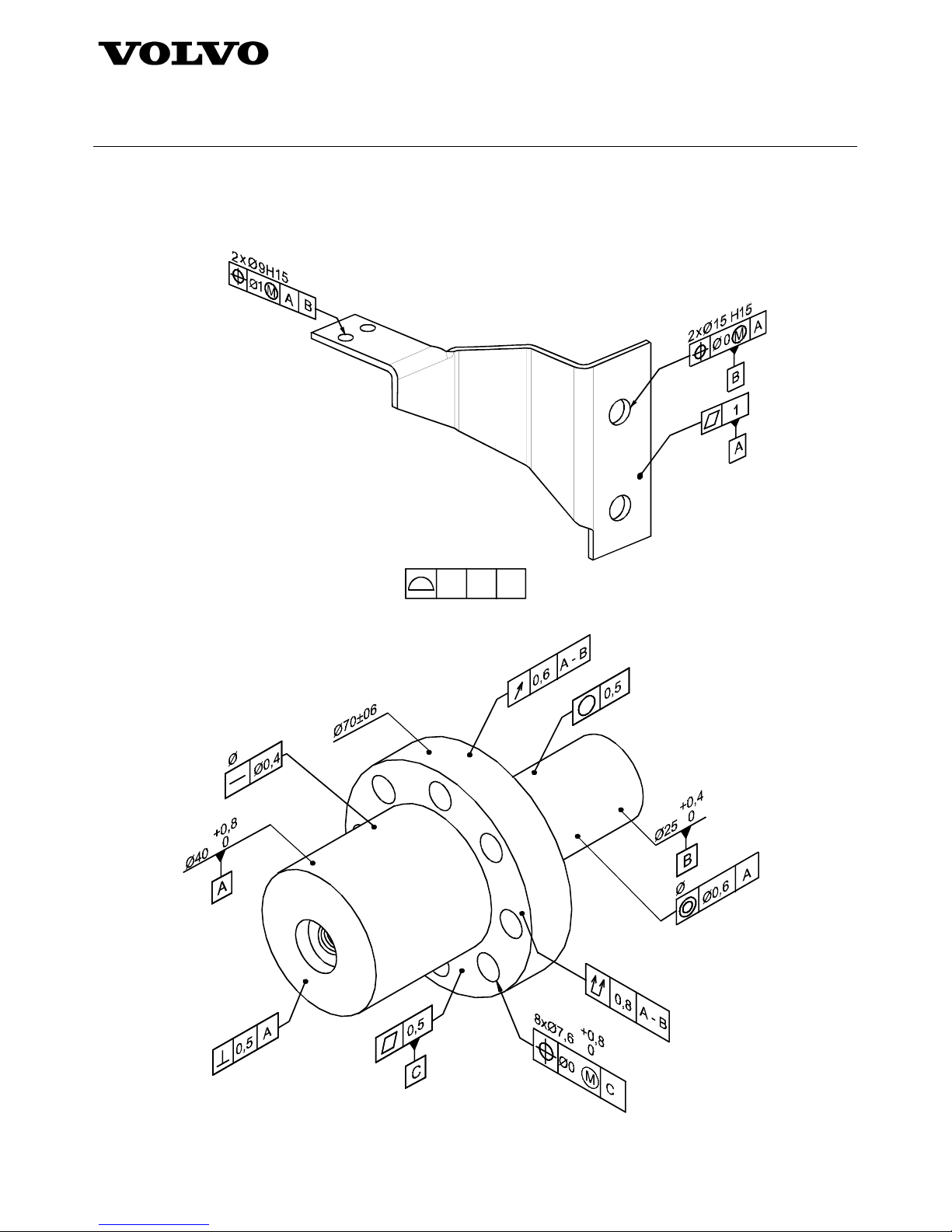
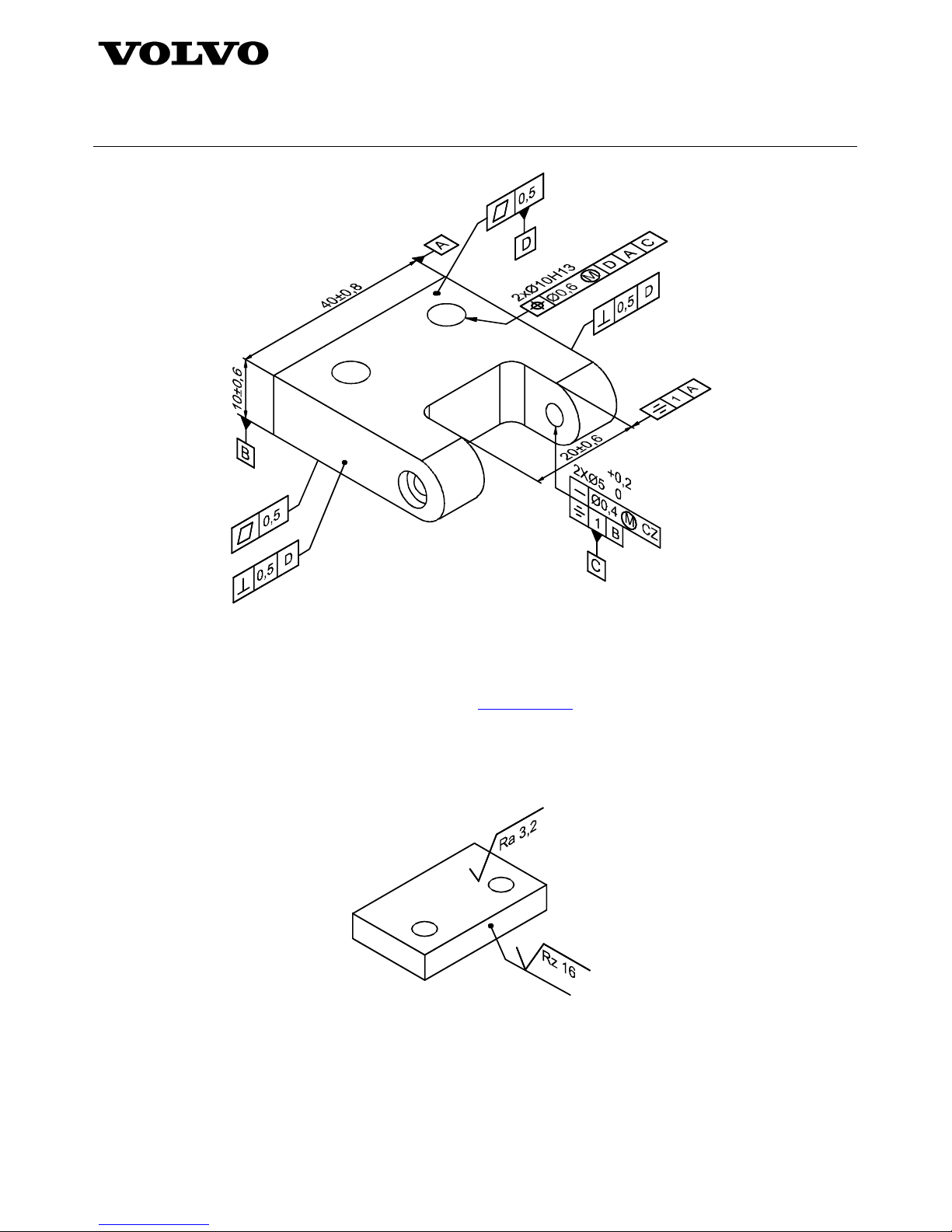
4.7.2 Examples of geometrical tolerance indications
The examples shown in figures 33, 34 and 35 are only examples of indications made in accordance with the rules
of this standard and they are not intended to illustrate the complete definition of the parts in question.
General note:
UNLESS OTHERWISE STATED:
1 A B
Figure 33
Figure 34
Page 33
Standard STD 101-0001
Volvo Group
Version
4
Page
33
Figure 35
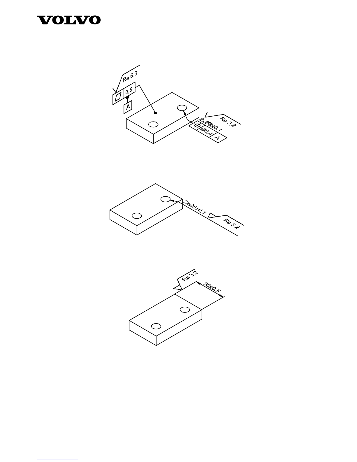
4.8 Surface texture
This section provides rules for connecting the graphical symbol for surface texture to 3-D model feature s
concerned. Some of the rules differ from the ones given in
STD 120-0004 which mainly are intended for the
specification of surface texture requirements on orthographic drawings.
The graphical symbol shall not be attached to single extension lines of model feature outlines.
The graphical symbol can be attached directly to the surface or to a reference line which have a leader line that
terminates with a dot on the surface. See figure 36.
Figure 36
The graphical symbol can be attached to a tolerance frame for geometrical tolerances, see figure 37.
Page 34
Standard STD 101-0001
Volvo Group
Version
4
Page
34
Figure 37
NOTE: This is the same rule as in 2-D
The graphical symbol can be attached to the dimension in connection with a feature-of-size dimension.
See figure 38.
Figure 38
NOTE: This is the same rule as in 2-D.
The graphical symbol can be attached to extension lines that are not single. See figure 39.
Figure 39
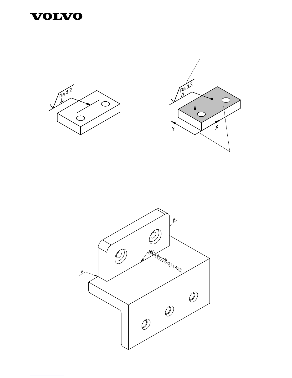
Two of the symbols for indication of surface lay described in
STD 120-0004 have an interpretation rule which is
unambiguous for indications on orthographic drawing views only. These are the symbols used for requirements of
the surface lay orientation to be parallel or perpendicular to the plane of projection.
When these two symbols are used in 3-D, there is a need to use supplemental geometry or a model-coordinatesystem vector to define a direction that shall correspond to the projection plane for orthographic views. The symbol
for indication of surface lay will then tell if the surface lay shall be parallel or perpendicular to the supplemental
geometry or model-coordinate-system vector, see examples in figures 40 and 41.
The rules how to use supplemental geometry or model-coordinate-system vector are described in sectio n 4.3.3.6.
Page 35
Standard STD 101-0001
Volvo Group
Version
4
Page
35
Query
Z
Visual response
Figure 41 - Dire ction through model coordinate
system. Direction of lay parallel to the X coordinate axis
Figure 40 - Dire ction through supplemental geometry.
Direction of lay perpendicular to the
represented line element
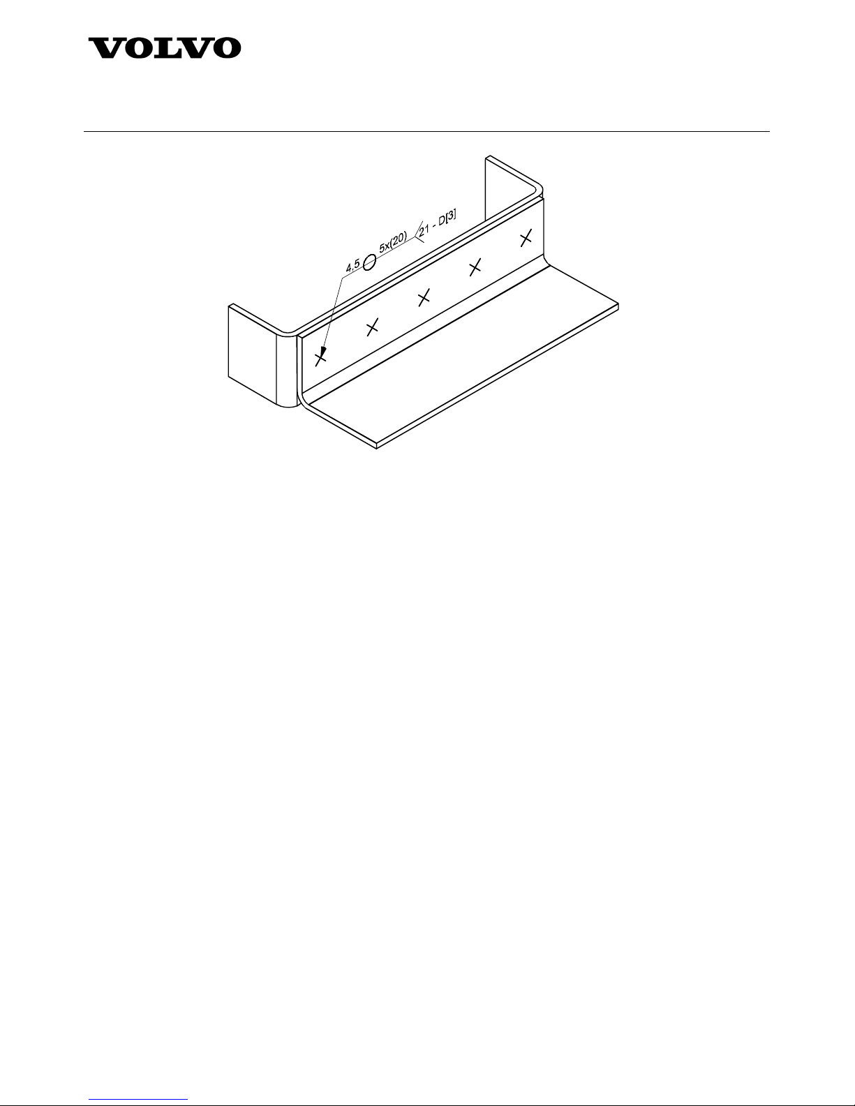
4.9 Other applications of 3-D annotation
It is possible to apply the rules stated in this standard for those types of requirements that are suitable to specify by
using 3-D annotation, e.g. to specify various types of joining requirements. The features concerned shall then be
associated to the annotated requirements. Figures 42 and 43 show examples of symbolic representation of welds.
Figure 42 – Symbolic representation of a fillet weld using 3-D annotation
Page 36
Standard STD 101-0001
Volvo Group
Version
4
Page
36
Figure 43 – Symbolic representation of a spot weld using 3-D annotation
5 References to this standard on model
When a model, but no drawing is used, and the model is created in accordance with the rules given in this
standard, the following note shall be specified in the model-annotation plane for general notes:
DIGITAL PRODUCT-DEFINITION DATA PRACTICES
STD 101-0001
 Loading...