

Volvo 9700 PRESTIGE PLUS Driver's Easy Reference
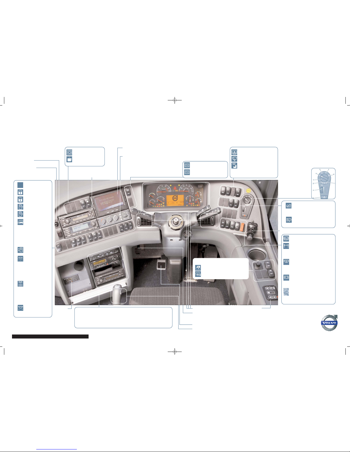
VOLVO 9700 PRESTIGE PLUS DRIVER’S EASY REFERENCE
This is intended as a quick reference guide only. Please ensure that you read the Driver’s Handbook. Please take notice of any warning lights before driving.
Please note, layout may vary due to vehicle specification
Volvo Bus, Volvo Group UK, Wedgnock Lane, Warwick CV34 5YA
Tel: 01926 401777 Fax: 01926 407407 www.volvobus.co.uk
Activate Toilet
Central locking left
luggage hatch
Central locking right
luggage hatch
Rear door control
Front door control
Kneeling
Press switch to
lower to lowest
entry height - Press
upper part of switch
to return to normal
driving height
N.B. Ensure passengers are clear of the
vehicle prior to activating
Enables opening of
doors from outside
Interior lighting
1st position complete interior
lighting, 2nd
position - partial
interior lighting
(front lighting
switched off)
Passengers’
individual lighting
Position 1 - All
lamps are turned on
Position 2 - Individual
passenger control
of lighting
Night lighting
DVD Please refer to separate operating instructions manual
Digital tachograph Please refer to separate operating instructions manual
Radio (4 Channel System) Please refer to separate operating instructions manual
See overleaf for information
Volvo I-Shift
Please refer to operating
instructions manual
Webasto
Please refer to
manufacturer’s
manual for
operating
instructions
Steering wheel adjustment
Depress foot pedal to adjust
Release to lock
Infrared video
Infrared sat nav
Activate refrigerator
Activate water boiler
Satellite navigation and
camera monitor
Air conditioning controls
From left to right: Driver’s cab temperature
control; Driver’s cab vent direction control;
Air flow intensity; Activation of air recirculation
and AC; Passenger compartment temperature
control - For further information please refer to
operating instructions
Activate sun blind
Activate upper wipe
Activate driver’s lighting
TV/Navigation view switch
Flip down monitor switch
Volvo light switch
1 Pull out – activate rear fog lights; Push in –
activate front fog lights
2 Indicator light, front fog light
3 Indicator light, rear fog light
4 Rheostat for instrumentation lighting
5 Hazard warning light
a Lighting off or
automatic dimmed
lighting
b Parking lights
c Driving lights
d Spot lights
Handbrake
Hill start aid
Temporarily disengage Traction
Control System (TCS)
Press once to disengage TCS,
press again to re-engage TCS
N.B. Not suitable when towing
Level control
To adjust ground clearance of
vehicle press bottom part of switch
to lower, and top part to raise the
vehicle
Main switch
Disconnects all large power
consumption sources
N.B. Never use whilst the engine is running
Emergency electrical cut-off
N.B. Only for use in emergencies
When activated will shut down engine, disconnect
electrical power & close fuel supply. To activate lift
cover upwards and press switch
Parabus electric
roof hatch controls
Please refer to manufacturer’s operating
instructions manual
Mirror adjustment
Activate driver’s electric window
Activate heated mirrors
Volvo Sound & Vision controls
Driver’s microphone switch
Increasing load on the driving
axle (bogie lift)
The drive axle load is increased by
pressing this switch
Activate headlight washers
The headlight washers are only
active when the lights are on
WC
J10281 - Cab layout.QXD 29/6/10 11:28 Page 1
WHEN PRODUCTIVITY COUNTS
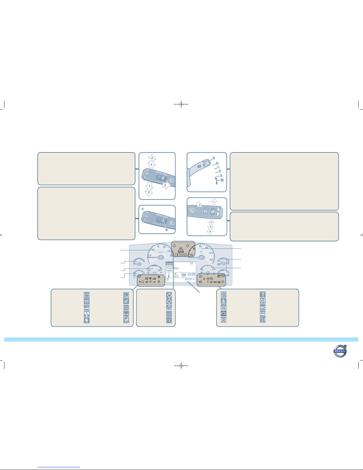
Tachometer
Under normal conditions the green zone gives best driving economy.
Use the dark zone for most effective engine braking.
N.B. Avoid the red zone. Such high speeds can damage the engine & gearbox.
Fuel gauge
The display gives more detailed fuel information, such as consumption,
remaining supplies etc. Please refer to separate publication.
Coolant temperature gauge
N.B. Do not drive vehicle if temperature exceeds the red zone as this can damage the engine.
Turbo pressure gauge
The indicator should remain still and be in the green zone to optimise fuel consumption.
Engine oil pressure gauge
N.B. If warning light comes on while driving, stop engine and locate cause.
Battery not charging
Pre-heating on
Kneeling activated
(for easier access)
Stop at the next lay-by
Service personnel
For more information on the Volvo display,
please refer to Driver’s Handbook
Screen/mirror
heating activated
The bogie unweighting
switch is on
Door brake activated
Differential lock activated
Exiting or entering
vehicle with pram
Left indicator on
Right indicator on
Stop, there is a fault
in the vehicle
Check
Information message
Main beam
Seat belt reminder
Parking brake applied
On-Board Diagnostics
Only applies to buses in emission
classification
Euro4 or later.
ABS not functioning
Check the tachograph
Rear fog light lit
WC engaged
WC tank full
Fault in the door
Direction indicator, dipped/full beam
1. Flick position
Press lightly and hold for slight direction changes (lane changing, overtaking).
2. Move past the flick position
The indicator will remain on until manually returned or the steering wheel is returned.
3. Headlights
Pull lever towards steering wheel until resistance is felt.
High beam headlights will remain until lever is released. To alternate between main and
dipped beam, pull lever all the way towards the steering wheel and release.
Idling
Normal engine idling speed should be 575-625 rpm.
Toalter the idling speed the engine must be warmed to operating temperature.
To activate, slide switch(B) to ON
Toincrease idling speed press the + end of the SET button (A)
Tolower idling speed press the - end of the SET button (A)
Each button press alters speed by 10rpm.
N.B. Change in idling speed is temporary. Pressing a pedal, engaging a gear or
releasing the parking brake will return to manufacturer settings.
Cruise control
To activate slide switch (B) to ON position.
When vehicle reaches required speed press the + or – side of the SET button (A),
which should also be used to increase or decrease the vehicle speed.
Cruise control is deactivated when brake or clutch pedal is pressed or the
retarder lever changed, and can be reactivated by placing slide switch in RESUME position.
Alternatively, it can be deactivated by moving slide switch (B) to the OFF position.
Retarder
Switch position 0 – Retarder off.
Switch position A – Retarder is automatically activated with service brakes when brake pedal pressed.
Switch position 1-3 –Retarder is activated without use of brake pedal, retarder will activate when
accelerator pedal is released – Retarder force highest on 3, lowest on 1.
Switch position B – only functions on vehicles with I-Shift - adapt gear shift for maximum braking.
N.B. Retarder acts on drive wheels only. Avoid using retarder in slippery conditions due to increased risk of skidding and wheel locking.
Speed limiter
Driven downhill with the switch in the A position, the retarder functions as a speed limiter. When at the
required speed press the + or – side of the SET button. The vehicle will retain the current speed. It can be
increased or decreased by pressing the + or – side of the SET button. Each press alters the speed by 1km/h.
N.B. Only applies to a lever controlled retarder. Foot controlled retarder activated by switch.
Combined cruise control and speed limitation
The retard lever should be in position A.
When driving downhill with cruise control activated, the retarder will engage when speed increases to
more than 5km/h above the set speed. Setting can be adjusted using +/- button.
N.B. Retarder automatically deactivated if there is a risk of wheel locking.
N.B. If high retarder temperature is displayed a lower shifting range must be selected to cool down retarder.
Windscreen wipers
1.
Intermittent wiping – i.e. drizzle conditions.
The default is 10 seconds. For shorter intervals move lever to normal position and then to the
intermittent position again when the next stroke should occur. This function will adjust the interval
between 1-10 seconds.
2.
Flick wipe is for 1-2 wipes. Move lever to flick wipe position and hold. Release as appropriate.
3.
Wipers at normal speed.
4.
Wipers at high speed.
5.
Windscreen and headlight washers.
Speedometer
Air pressure gauges for brakes
Whilst driving the gauge should be in the green zone.
Please refer
to ‘Operating
Instructions
Display’
manual
VOLVO 9700 PRESTIGE PLUS DRIVER’S EASY REFERENCE
This is intended as a quick reference guide only. Please ensure that you read the Driver’s Handbook. Please take notice of any warning lights before driving.
J10281 - Cab layout.QXD 29/6/10 11:29 Page 2
 Loading...